

Page 1

Thank you for choosing a Maxmatic Waste Disposal Unit
Further information and updates to these instructions are available at
www.max-appliances.co.uk
MAXMATIC
Domestic Food Waste Disposal Unit Operating and
Installation Manual for 5000 / 4000 / 4000C / 3000 / 2000
Please attach proof of purchase to this booklet
and keep it in a safe place with the de-jam key.
Don’t forget to return the registration card within 14 days together
with a copy of your proof of purchase to receive your extensive
manufacturer’s warranty, if not registered within 14 days of the
purchase date the statutory 12 month warranty will apply.
...............................................................
Your Serial Number
Aug 2013
Page 2

Contents
3) How to use your Maxmatic waste disposal unit
4) General Installation guide, plumbing, electrical
5) Installation - 5000, 4000, 3000, 4000 Classic & 2000
6) Installation diagrams
7) If your Disposer Stops Working & Warranties
8) General Information
NOTES
Page 3

Guarantee
Thank You for choosing
The greener option for your kitchen waste.
Please complete the registration card within 14 days, return
complete with a copy of proof of purchase to receive your
extensive manufacturer’s warranty, if not registered within 14
days of purchase date the statutory 12 month warranty will apply.
www.max-appliances.co.uk Email: [email protected]
PLEASE ATTACH PROOF OF PURCHASE HERE
SERIAL NUMBER
NAME
ADDRESS
POSTCODE
TELEPHONE
PURCHASED FROM
DATE OF PURCHASE
DATA PROTECTION: We request this information to enable us to provide an
effi cient after sales service
Page 4

MAX APPLIANCES LTD.
FREEPOST SEA 11333
HASTINGS
TN35 4BR
PLEASE FOLD HERE AND SEAL
Page 5

HOW TO USE YOUR MAXMATIC
5000 & 3000
1) Remove the Magnitop plug and load the unit - do not cram the waste into the unit.
2) Replace the plug in the “Drain” position.
3) Turn on the COLD tap - a good fl ow is required.
4) Turn the Magnitop plug to the “GRIND” position and the unit will start.
5) When the grinding has fi nished, allow the unit to run for about 10 seconds.
6) Turn the Magnitop plug to the “DRAIN” position and turn off the water.
The 5000 is also supplied with a Magnitube and can be used as a continuous feed unit as
described below for the 4000.
4000
1) Place the Magnitube in to the unit at the “Drain” position.
2) Turn on the COLD tap - a good fl ow is required.
3) Turn the Magnitube to the “GRIND” position and the unit will start.
4) Feed the food waste into the unit - Use a tool like our Dispos’l Mate to push food through the
splashguard, not your fi ngers.
5) When the grinding has fi nished, allow the unit to run for about 10 seconds.
6) Turn the Magnitube to the “DRAIN” position and turn off the water.
If you wish to dispose of larger items the Magnitube can be removed to pre load the unit.
4000 Classic & 2000.
1) Remove the rubber sink plug.
2) Turn on the COLD tap - a good fl ow is required.
3) Turn on the unit with the air switch or wall switch.
4) Feed the food waste into the unit - Use a tool like our Dispos’l Mate to push food through the
splashguard, not your fi ngers.
5) Once the waste is disposed off, allow the water and unit to run for about 10 seconds and
switch off.
GENERAL
DO’S
Disposing of your prep and mealtime waste only takes a few seconds, so don’t leave your
disposer running and go and do something else, it should be attended while in use.
A) Add a little of your own common sense to these instructions
B) Run a good fl ow of cold water before you start your disposer
C) Always maintain a good fl ow (Min 4 litres per Minute) of COLD water to carry the waste away.
D) Break up large items to assist even distribution within the grinding chamber.
E) Break up bones into smaller lengths to aid in speeding up their disposal.
F) Mix the various types of waste which will help to dispose of stubborn items more speedily.
G) Stay with the disposer while it is running.
H) Allow the machine to rest after large loads.
DON’T
A) Put metal, plastic, string, glass or cloth into the disposer. These items cause either jamming of the
unit or plumbing, and some may cause damage, and subsequent failure of water seals in the unit.
B) Use heavy concentrates of detergents or bleaches in the sink housing the unit.
C) Use hot water - this causes grease to congeal in the waste pipe, and subsequent blockages.
D) Don’t run for long periods, this is a domestic machine which can run for 10 minutes maximum
at any one time.
E) Try to dispose of large raw bones, stringy materials or large pieces of raw fat.
CLEANING
Using plenty of water when disposing of waste and the normal passage of soapy waters will
usually keep the unit clean. Occasionally use a sachet of Disposer Care available from Max
Appliances.
3
Page 6

GENERAL INSTALLATION INFORMATION
PLUMBING
A) The waste pipework must be installed to ensure that the unit drains completely.
B) A ‘P’ or an ‘S’ trap must be fi tted. DO NOT USE A BOTTLE TRAP.
C) The waste MUST not discharge over a gulley or drain grating.
D) The waste pipes should not be less than 38mm in diameter.
E) A minimum fall of 15 degrees is recomended.
F) The waste run should be as short as possible avoiding, sharp bends, tee connections, and
stopped ends.
G) All connections and joints must not restrict the internal diameter of the pipe, check manifolds
for internal baffl es, as these will cause blockages.
H) The sink must have an 89mm (3 1/2”) diameter waste hole, and must be fi rmly fi xed to its
supporting cabinet unit. Suffi cient space within the cabinet is required to allow easy access to
the disposal units controls.
I) Where a lengthy, or meandering run of pipe work is unavoidable, It is recommended that the
pipe size be increased to 54mm (2”) diameter immediately after the trap.
J) Make sure that the installation of the appliance is allowed by the authorities.
K) The Outlet connector will need the seal inside the spout to be removed if necessary for
additional use.
L) In some cases the installer may include extra charges if cupboard shelving and plumbing has
to be altered or removed to gain access to the unit.
ELECTRICAL - WARNING - The unit must be earthed.
A) The appliance must be installed in accordance with I.E.E regulations.
B) The supply must be of the correct voltage and frequency.
C) The current rating of the BS 1362 fuse to be used on this unit is 13A and only ATA approved
fuses are to be used.
D) The unit must be connected to the supply by means of a non-detachable fl exible cord
E) Means for disconnection must be incorporated in the fi xed wiring in accordance with the
wiring rules, ideally, via a 13amp double pole switched spur.
F) If the supply cord is damaged a replacement should be obtained from the manufacturer. The
cord must then be replaced by the manufacturer, its service agent or similarly qualifi ed persons
in order to avoid a hazard.
G) When installing the unit, care must be taken that the overload reset button and Reverse Switch
(where fi tted) are readily accessible.
H) The wires in the mains lead are coloured in accordance with the following code
Green and Yellow - Earth
Blue - Neutral
Brown - Live
4
Page 7

5
Installation - 5000, 4000, 4000 Classic, 3000 and 2000
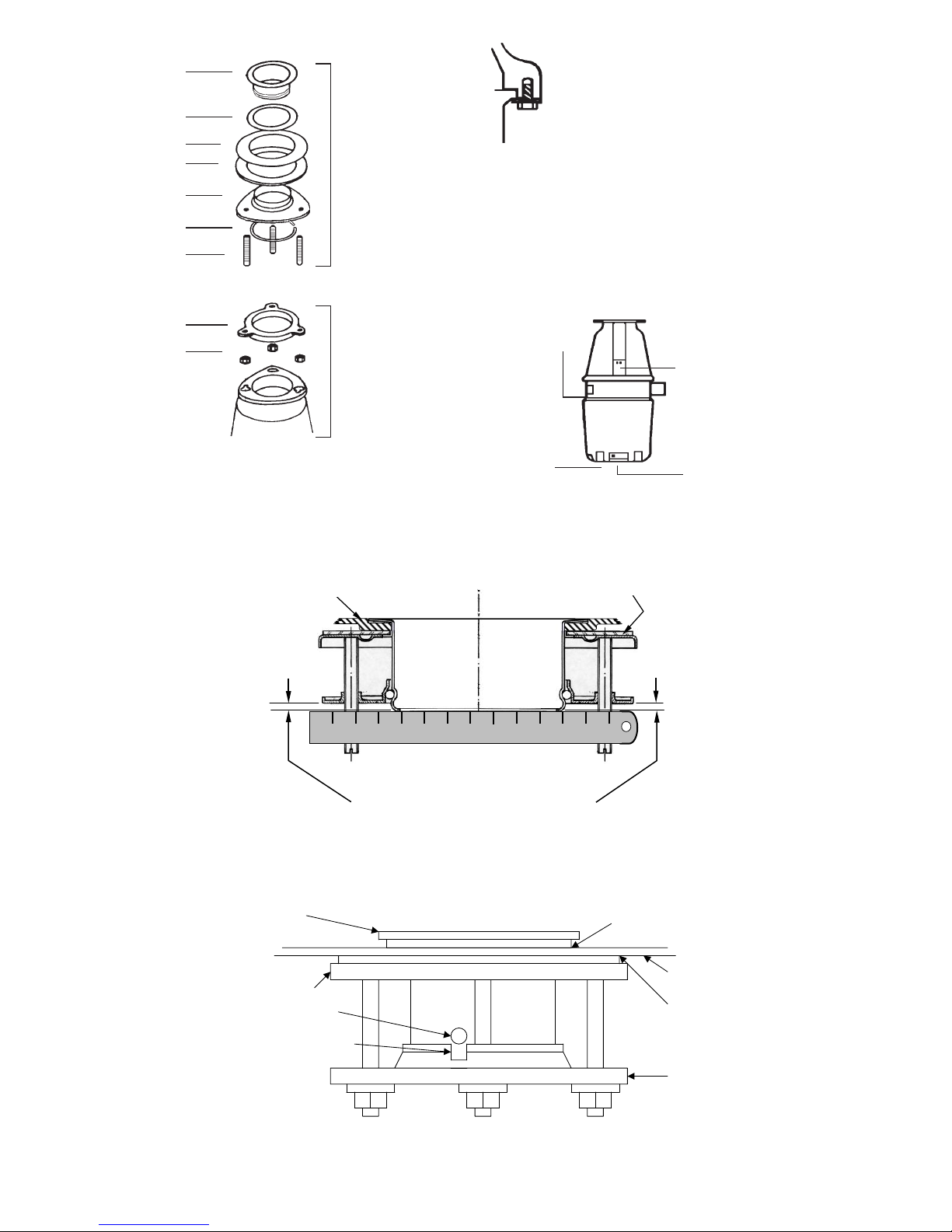
Step1 - Fitting the sink bush assembly (See Fig.1 - Stage 1).
1.1) Remove the sink bush assembly from the unit by fi rst loosening the three-nuts (9), and twisting
the assembly clockwise in the hopper fl ange keyholes.
1.2) Slacken off the three-grub screws (7) suffi ciently to push the Suspension Plate (5) up the Sink
Bush (1) to enable you to remove the circlip (6) by twisting a fl at bladed screwdriver underneath
the clip at it’s joint from the side, slide off all the components from the sink bush, with the
exception of the Inlet Gasket (2).
1.3) Position the sink bush in the sink waste outlet hole so that the line with the arrowhead and the
word GRIND is positioned at 9 o’clock relative to the front of the sink unit. Check that it is fl ush
or below the sink bowl surface and that it has a good seating. If not, remove the inlet gasket and
substitute with a layer of plumbers putty or suitable sealant.
FOR 4000 CLASSIC AND 2000
Position the sink bush in sink waste outlet hole so that the MAXMATIC engraving is at the front of the
sink i.e 6
o’clock. Check that it is fl ush or below the sink bowl surface and that it has a good seating.
If not, remove the inlet gasket an substitute with a layer of plumbers putty or suitable sealant.
1.4) From the underside of the sink, position the lower waste inlet gasket (3), followed by the clamp
plate (4) (with the outer edge is turned downwards). Push the suspension plate up onto the sink
bush as far up as you can, to reveal the groove around the sink bush that holds the circlip and
then push the circlip up the sink bush until it snaps into the groove.
1.5) You may now release the suspension plate and allow it to rest on the circlip and then rotate it
until the slot (see Fig.5) in the edge of the plates upper rim is in line with the pimple on the sink
bush. Tighten up the grub screws by hand a few turns to each in rotation so that the suspension
plate remains parallel to the clamp plate. see fi g 4. Finally, tighten with a screwdriver Do Not
over-tighten the grub screws, as this will cause distortion of the Suspension Plate.
Step 2 - Fitting the unit to the sink bush assembly (Fig.1 - Stage 2).
2.1) Fit the Hopper Seal (8) on to the three grub screws fl attest side up, the bottom edge of the sink
bush will locate in the recess on the top of the seal.
2.2) Fit the three nuts and washers, to the grub screws only a few turns.
2.3) Offer up the disposer with the control box facing towards you ensuring that the nuts and washers
fi t through the large holes of the keyholes and turn the disposer clockwise, so that the grub
screws move into the keyhole slots and rest the disposer on the washers above the nuts.
2.4) Tighten up the three nuts evenly ensuring that the hopper seal is correctly seated. DO NOT over-
tighten the nuts as this will cause the hopper seal edge to bulge into the waste inlet, which will
hamper the movement of the Magnitop Plug. Over tightening may also cause the hopper to distort
resulting in a leak.
Step 3 - The disposer is now ready for the waste plumbing and electrical connections.
3.1) If required the bottom half of the disposer with the waste outlet can be rotated to make the
plumbing easier. To do this slightly slacken off ALL six bolts around the underside rim of the
hopper (if one is not slackened the hopper seals may be twisted out of position and the cutter
ring could be misaligned). Gently rotate the lower section of the unit to the required position and
tighten the six bolts (see Fig.2).
3.2) Connect to the drain and electrical supply by following the general instructions on page 4.
Step 4 - Testing
4.1) Insert the Magnitop Plug into the sink outlet and turn to the “SEAL” position and half fi ll the
sink with water and check for leaks around the underside of the sink (The 4000 model does not
include a Magnitop plug so the stainless steel plug supplied is used). Turn the Magnitop plug to
the ‘DRAIN’ position and check all joints for leaks.
FOR 4000 CLASSIC AND 2000
Insert the plug into the sink outlet and half fi ll the sink with water and check for leaks around the
underside of the sink. Remove the plug and check all joints for leaks.
4.2) Set the switch on the front of the control of the unit to the ‘ON’ position (Fig.3) Please note that the
switch is not used to activate the machine and is merely supplied as a means of reversing cutting
rotation. Check the power and test the operation of the unit by following the instructions on page 3.
4.3) Attach proof of purchase to this booklet and keep it in a safe place with the de-jam key. Don’t
forget to return the registration card within 14 days together with a copy of your proof of
purchase to extend your warranty. If not registered 12 months statutory warranty will apply.
Page 8
6
Figure 1
Stage 1
Stage 2
1
8
7
6
5
4
3
2
9
Reset Button
on the base
opposite the
waste outlet
Loosen all the six screws to
enable the lower section of
the appliance to rotate.
When position has been set
Evenly retighten screws.
Look inside the hopper to
be sure the seals are located
correctly.
Figure 2
Figure 3
Machine Serial No
Reverse Switch
4000 Classic
& 2000
Reverse Switch
5000/4000/3000
10 20 30 40 50 60 70 80 90 100 110 120 13
0
SECTION OF
SINK OUTLET
SINK BUSH
ASSEMBLY
THESE GAPS MUST BE EQUAL
fi gure 4
fi gure 5
Sink Bush
Clamp Plate
Sink Bush Dimple
Suspension Plate Slot
Upper Inlet Gasket
Sink Base
Suspension Plate
Lower Inlet Gasket
THESE GAPS MUST BE EQUAL
ALL THE WAY AROUND
Page 9

If your Disposer Stops Working
An overload switch protects your Maxmatic disposer. This will turn off the power in the event of a
jam, overloading, or if the unit is left running for a prolonged period.
1) FIRST TURN OFF THE POWER SUPPLY.
2) If your unit has a reverse switch, select the centre “OFF” position.
3) Allow the unit to cool for a few minutes.
4) You will fi nd the RED reset button on the BOTTOM of the unit, press it with your fi nger.
5) Select either “ON” position on the reverse switch if your unit has one.
6) RESTORE THE POWER SUPPLY.
7) Try the unit.
IF THIS FAILS
8) Repeat steps 1 to 3 above
9) Insert the DE-JAM key supplied with your unit and turn in both directions until it rotates freely.
10) Remove the DE-JAM Key
11) Repeat steps 4 to 7 above.
IF THIS FAILS
12) Check that your power supply is not fused and that your air switch or wall switch is working.
13) Contact Max Appliances on 01424 751666 for more help.
WARRANTY
Providing our installation and operating instructions have been carefully observed, this waste disposer is
guaranteed to the REGISTERED original purchaser, to be free from defects in material and workmanship for
the periods specifi ed below.
Standard model Labour Parts
3000 2 years 2 years
2000 2 years 2 years
Deluxe model Labour Parts
5000 2 years 10 years service exchange
4000 2 years 10 years service exchange
4000 Classic 2 years 10 years service exchange
This guarantee does not apply to any detachable items (rubber plug, splashguard, Magnitube or Magnitop
plug), and any costs incurred in the rectifi cation of either faulty installation or jammed machines. Furthermore
this guarantee does not apply where a machine has been abused in circumstances in which we would
normally consider a commercial machine applicable (e.g. establishments providing more than 10 meals per
sitting, or on a continuous or semi-continuous sitting) If your machine is not registered within 14 days of
purchase statutory 12 months warranty will apply. Inspect product for damage during transport, as the
cost of an aborted installation visit cannot be claimed. Proof of purchase must be in registered name of
end user.
For service contact us on 01424 751666 for your nearest service agent. You will be asked
to quote the serial number to identify your machine and check registration.
7
Page 10

8
GENERAL INFORMATION
Fitted with a commercial Magnitop Magnitube Air or Wall Switch
Grinding system Batch Feed Continuous Feed Continuous Feed
5000 * * *
4000 * *
4000 Classic * *
3000 *
2000 *
Batch feed
Waste is placed in the hopper and then a Magnitop plug is used to close off access and
then turned to start the unit.
Standard Continuous Feed
The unit is started either with an electrical wall switch or bench mounted air switch,
waste is then fed continuously.
Magnitube Continuous Feed
The unit is started by twisting our patented Magnitube and waste is then fed through it.
Max Appliances Limited
Kingfi sherHouse
Wheel Park, Westfi eld
East Sussex, TN35 4SE
Tel: 01424 751666 Fax: 01424 751444
Email: [email protected] Web: www.max-appliances.co.uk
IT IS OUR POLICY TO CONTINUALLY IMPROVE OUR PRODUCTS AND WE RESERVE THE RIGHT TO
IMPLEMENT DESIGN CHANGES AT ANY TIME WITHOUT PRIOR NOTICE.
CHECK WWW.MAX-APPLIANCES.CO.UK FOR THE LATEST INSTRUCTIONS AND SPECIFICATIONS
 Loading...