

Page 1

Users Guide for MP370
Touch Panel Control System
Page 2

Table of contents
Screens
Home
...................................... pg 3
Component
..............................
pg 4
Calibrate
................................
pg 5
Component Alarm
...................
pg 6
Component PID Temp
...............
pg 8
Component PID Flow
................
pg 9
Heater
...................................
pg 10
Heater Alarm
..........................
pg 11
Heater PID Temp
....................
pg 1
2
Chiller
....................................
pg 13
Chi
ller Alarm
...........................
pg 1
4
Mixer
.....................................
pg 15
Mixer Alarm
............................
pg 16
Mixer Purge/
Flush
/Lube
..........
pg 1
7
Vacuum Cold Trap
..................
pg 1
9
Vacuum Cold Trap Alarm
.........
pg 20
System
...................................
pg 21
Timer
.....................................
pg 22
Administration
........................
pg 23
Alarm Log
..............................
pg 24
Security Access
.......................
pg 25
Back up and
Restore
...............
pg 26
Screen navigation
.........................
pg 27
Please Note:
this manual is designed to be a quick reference guide and training aid in the use of
the MP370 machine interface. The operation of the Max urethane processor is easily mastered
and with this guide, yo
u will be able to operate the machine quickly and with confidence.
Areas regarding the mechanical systems and maintenance of the machine can be found in the
main processor manual.
Configurations and q
uestions not covered in this manual
should be referred
to the Technical
Service Department at Max Machinery, Inc (707) 433-7281
© Max Machinery, Inc. Rev. 7
/2/07
Page 3
Screens
Home
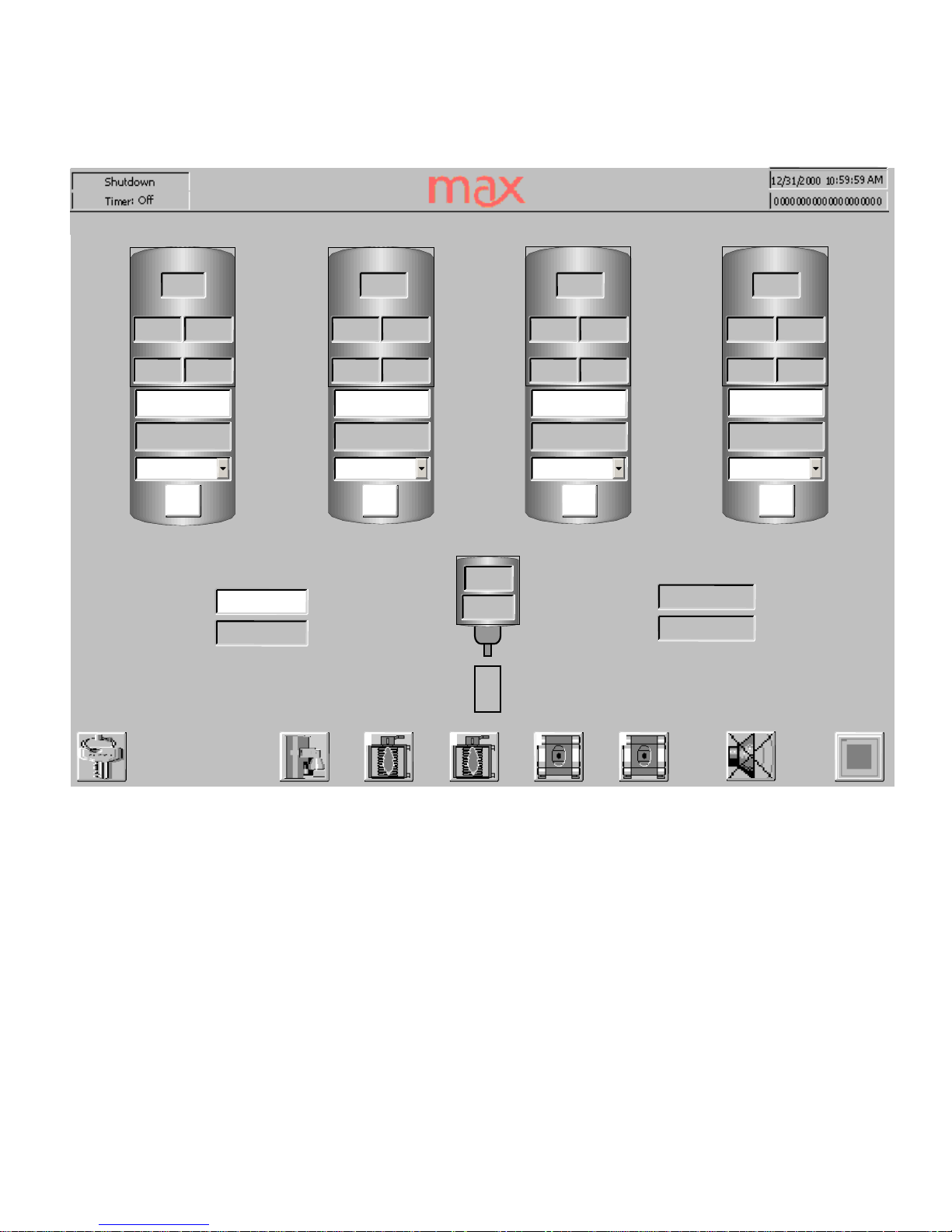
The Home Screen is the main operator interface to the machine. All standard operating
pa
rameters are displayed for easy verification of proper operation. Each tank icon contains that
components’ tank level, tank and processing temperature, pouring and recirculation pressure,
the flow set point, the actual flow rate the flow control mode and
whether the pour valve is
currently enabled.
The Mix head icon reports the current temperature and mixer RPM. To the left is an indication
of the shot time and sum of the flow set points. To the right is a report of the mixer switch
position and the prog
rammed response of the pot life timer.
If installed, t
he icons along the bottom access
Log
-out, recipes
(an optional function)
, the
heater
/chiller
(s), vacuum pump(s), the muting of the alarm and the System Screen
Touching the top half of the tank icon will
access the component screen and alarm input
screens.
_
User Name
_12/31/
2000 10
:59:59_
Run_Timer: Off_Total Delivery
_
Pour Time
_
Potlife Action
_
None
_
Mixer State
_
Off
_
OFF
_
C
_
OFF
_
D
_
OFF
_B_
000
°C
_
Tank_Pour_Recirc
_
000
°C
_
Line
_
000
°C
_
Tank_Pour_Recirc
_
000
°C
_
Line
_
000
°C
_
Tank_Pour_Recirc
_
000
°C
_
Line
_
000
_
OFF
_
A
_Pour_Recirc
_
000
°C
_
0000.00
_
g/min
_
0000.00
_
g/min
_
0000.00
_
g/min
_
0000.00
g/min
_
0000.00
_
g/min
_
0000.00
_
g/min
_
0000.00
_
g/min
_
0000.00
_
g/min
_
0000
ps
i
_
0000
psi
_
0000
_
psi
_
0000
_
psi
_
000
_
0000
psi
_
0000
psi
_
0000
psi
_
0000
_
psi
_
0000
_
rpm
_N_N_N_N_
0000.00
g/min
_
000
_
%
_
0000.00
_
sec
_
000
_
%
_
000
_
%
_
000
_%_
Line_Tank
°C
°C
_1_2_1
_2
Page 4
Screens
Component
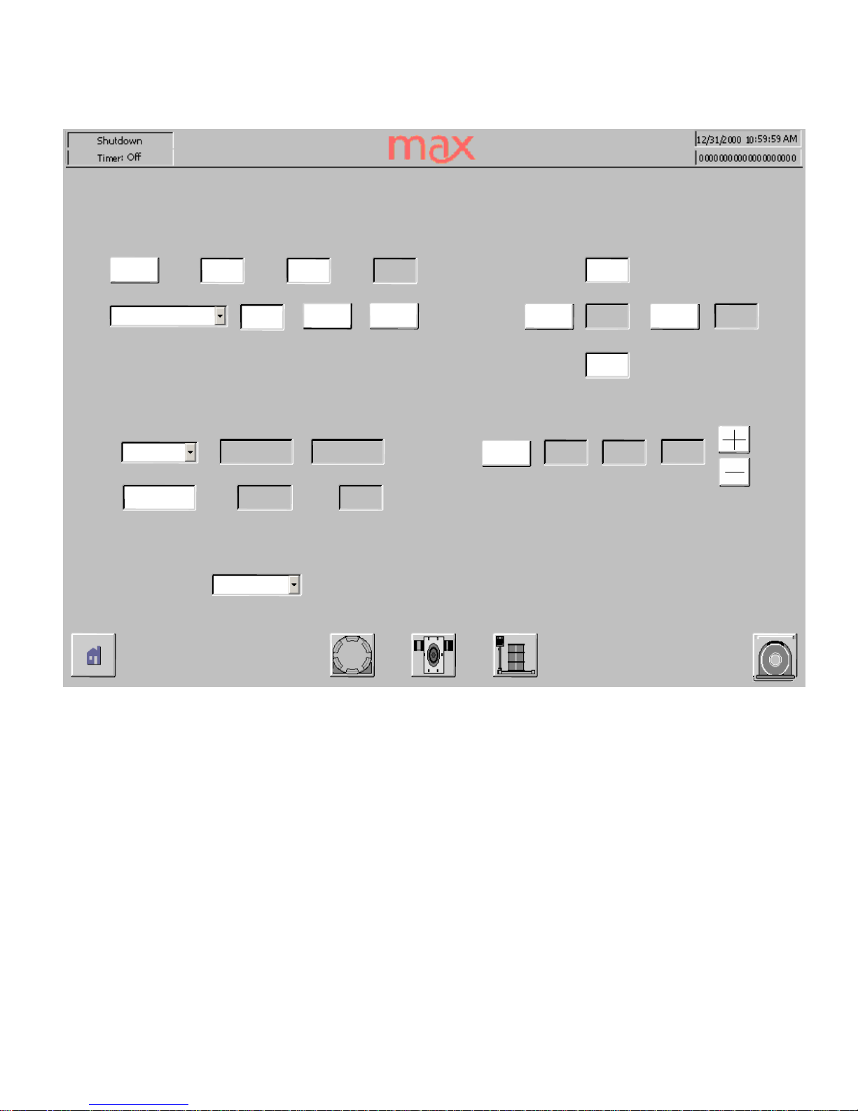
The Component screen is where the operator controls Temperature,
Flow Rate, Level and
Pressure.
The operator can also access the Temperature P.I.D, Flo
w Rate P.I.D, Calibration
and Component Alarm windows.
There are multiple temperature zones. The drop down menu allows you to individually select
the temperature offset of the zone relative to the process temperature shown above. Process
temperature typi
cally refers to Line temperature at the 3-way valve.
Level control will operate the automatic fill valve to start and stop the filling process. Note: to
start the flow from a new supply barrel may require cycling the control button several times
until th
e material reaches the fill valve level probe. A time out function is used to prevent the
imploding of empty barrels. Repeated
activations will rewet the probe.
Flow rate can be controlled by monitoring the pump speed or the flow meter output signal.
Se
lect the appropriate control point and input the set point for your recipe.
Pressure is usually controlled automatically. In the manual mode you can bias the recirculation
pressure for very short shots – please consult the factory for direction.
Agitator
control is an On/Off choice.
Icons at the bottom are links to the following pages.
_
_12/31/
2000 10
:59:59_
Run
_
Timer: Off
_
0000.00
_
OFF
_
Set Point
_
Error
_
0000.00_0000.00
_
g/min
_
0000.00
_
Control
_
Output
_
OFF
_
Control
_
g/min
_00.
0
_%_
%
_
Pour_Recirc_Delta
_
Pressure
_
0000_0000_0000
_
Mode
_
psi
_
Level_000
_
000
_
000
_
°C
_A_
A
_
Flowrate
_
Pumprate
_
Temperature
_A_
Flow Rate
_A_
Agitator
_A_
000
°C
_
000
°C
_
000
°C
_
000
_
Control
_
000_Off_Manual
_
Start
_
psi_psi_%_%_%
_
Tank Stop
_
Tank Level
_
Tank Start
_
Fill Valve
_
%
_
Text
_
g/min
_Fill Level
_
LINE
_
Zone_Current
_
Offset_Control
_
Off
_
Heat_Cool
_
Off
_
Run_Standby
_
Off
Page 5
Screens
Calibrate
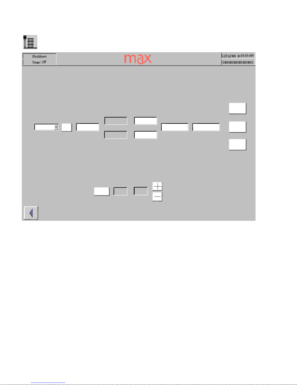
The Calibrate screen is used to calibrate the flow meter and pump output for an individual
component,
line
pressure can also
be monitored and controlled from the calibrate screen.
NOTE:
You cannot enter the calibration screen during a pour, flush or material purge of the
mix head. Entering or leaving this screen will set all pour valves to “N”
to prevent
unintentional pour
ing of chemicals.
Before any short duration shots are performed, the pour and recirculation pressure
need to be
balanced. Establish the flow rate you intend to use. Cycle the pour valve and compare the
displayed values. In automatic mode, the PLC will b
alance the two values. In manual mode,
you can use the +/- keys to adjust the recirculation pressure until it matches the pour pressure.
A
calibration check
should be done for both the Flow Control choice and the Pump Control
choice. (
In systems that do
not have flow meters
, only the Pump Control choice will be valid.)
The intended flow rate for this component should be entered as the Set Point. Select a pour
time that will create a sample of at least 100 grams. Push the “start pour” button on the mix
head control box, collect and weigh the sample. Input the sample weight into the “Measured
Pour” field and hit the “Calibrate” button.
Calibration values that exceed the
previously defined maximum Flow or Pump rate, or that
change the density value by mo
re than 10% will trigger a warning message. Double check the
weight and entered value before accepting the adjustment.
_
_12/31/
2000 10
:59:59_
Run
_
Timer: Off
_
0000.00_0000.00
_
Set Point
_
0000.00_0000.00_0000.00
_
Pour Time
_
000.00
_
sec
_
Control
_
Measured Pour
_
Pump Max
_
OFF
g/min
g/min
g/min
g/min
_
Flow Max
_
Flowrate
_
Pumprate
_
N
_
Pour
_
0000.00
g/min
gram
s
_
Calibrate
_
Reject
_
Accept
_
CALIBRATION CHANGED MORE THAN
10%_
CHECK YOUR SETTINGS
!!
_
Pour_Recirc
_
Pressure
_
0000_0000
_
Mode
psi
_
Manual
psi
_A_
Calibration
_
A
Page 6
Screens
Component Alarm
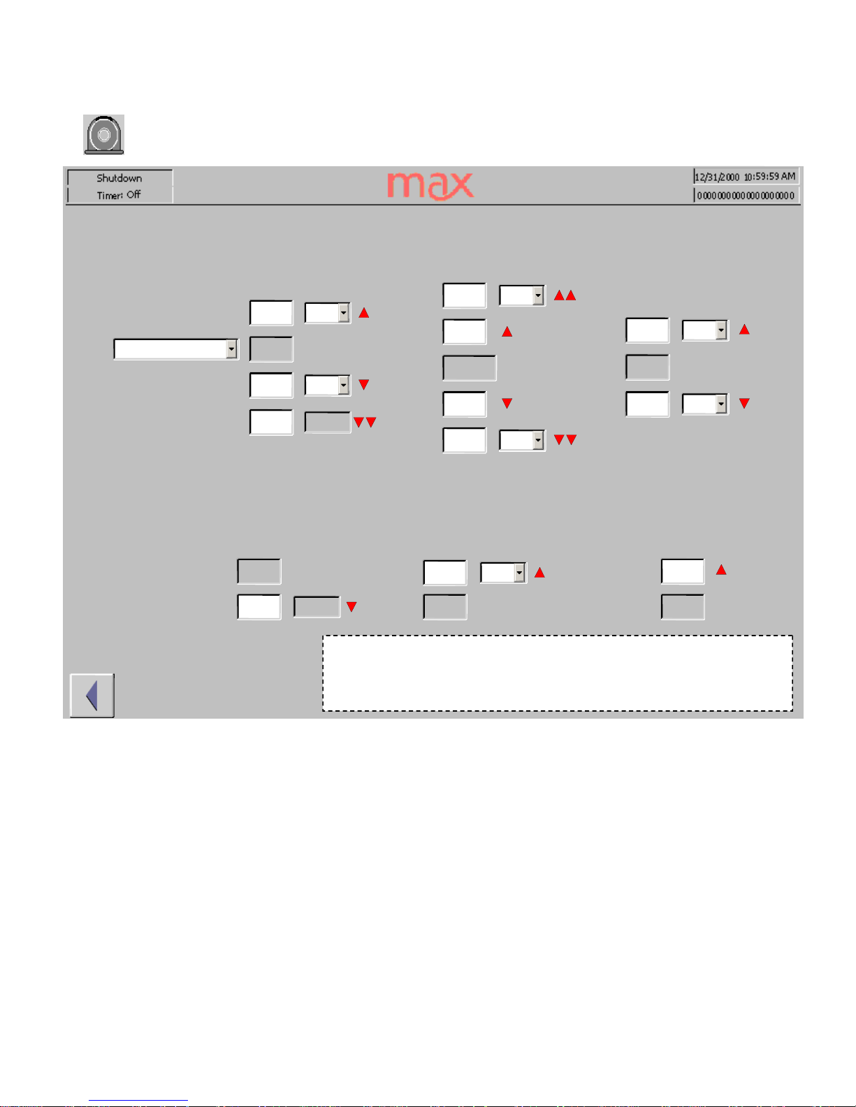
The Component Alarm screen is where the operator
sets alarm limits and actions for
component Temperature, Flow Rate, Level and Pressure.
Temperature: Select which zone to set alarm settings for by selecting the Zone list box.
Set the
desired Hi and Lo temperature alarm set points and the associated actions. The Lo 2
temperature
alarm set point value is an absolute value and
its action is hard coded as “MO”
-
motor off.
Flow Rate: Set the desired Hi1, Hi2, Lo1, Lo2
flow rate alarm set points and the associated
actions. All alarm set points are relative to the current flow rate.
Tank Level: Set the desired Hi and Lo Tank level alarm set points and the associated actions.
All alarm set points are absolute values.
_
_12/31/
2000
10:59:59_Run
_
Timer: Off
_
000_000
_
FS
_%_
%
_
000_000
_
NA
_
psi_psi
_
000_000
_
psi_psi
_
000_000_000
_NA_
NA
_%_%_
%
_
000_000
_NA_
NA
_%_
%
_000_000
_%_
%
_
0000.00
_
%
_
LINE
_
000_000_000
_NA_
NA
°C
_
Zone
_
000
°C
°C
_
MO
_
Tank Level
_A_
Flow Rate
_A_
Temperature
_A_
Fill Level
_A_
Pressure
_A_
Delta Pressure
_
A
°C
°C
Actions:
IP - Inhibit next pour SP – Stop pour
MO - Motor off FS – Filling stopped VO - Vacuum off
Page 7

Fill Level: Set the desired Lo supply level alarm set point. The Lo supply level alarm action is
hard coded
as FS.
Pressure: Set the desired Hi pressure alarm set point and the associated action. The Hi
pressure alarm set point is an absolute value.
Delta - Pressure: Set the desired Hi pressure alarm set point and the associated action. The Hi
pressure ala
rm set point is an absolute value.
Page 8
Screens
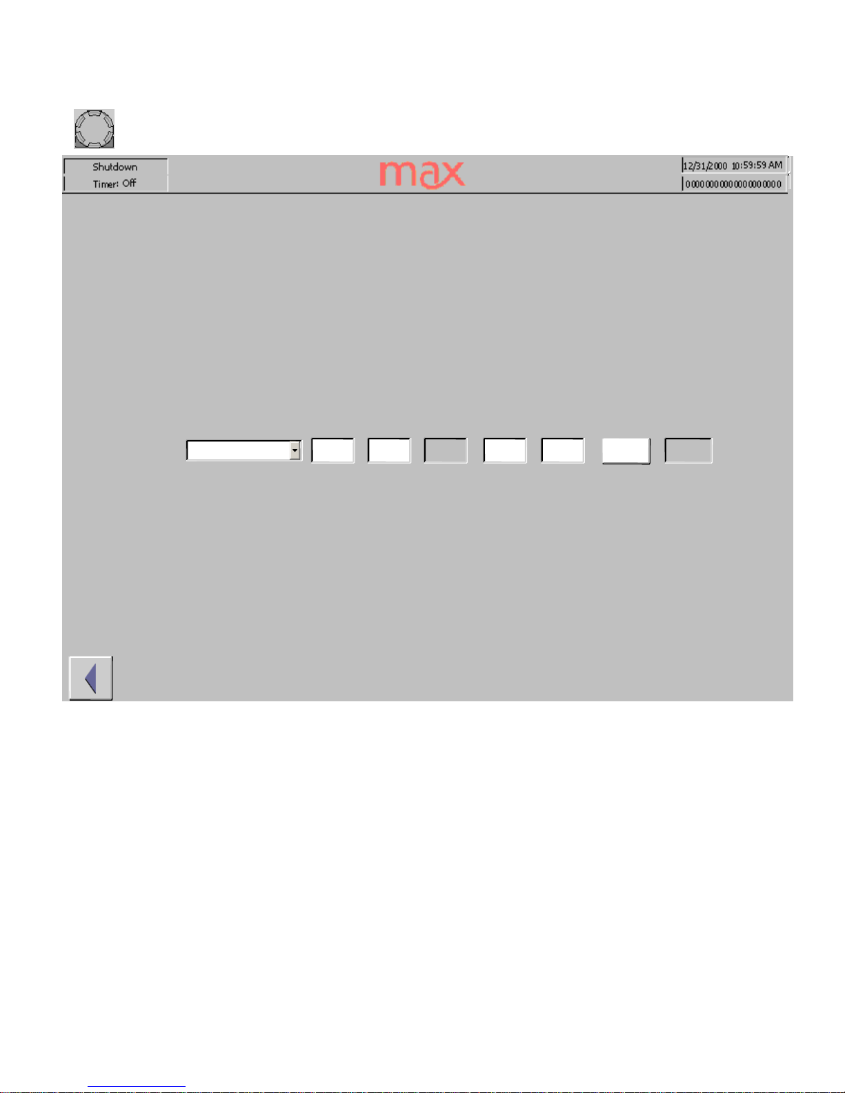
Component
PID
for
Temp
Each temperature zone has P.I.D. tuning for optimum temperature control. These values are set
at the factory and are based on the response rate of
the tanks, lines and other components to the
input of hot glycol. These values should not be adjusted without first consulting with the
Technical Service Department at Max Machinery.
_
_12/31/
2000 10
:59:59_
Run
_
Timer: Off
_
LINE
_
Current
_
Bandwidth
_
Duty
Cycle_Zone
_
Temperature P
.I.D.
_
Auto Reset
_
000
°C
_00.0_
000_0000
_
%
_
000
°C
_
000
°C
_
Run_Standby
°C
_
sec
_
A
_
PID Reset
_
Reset
Page 9
Screens
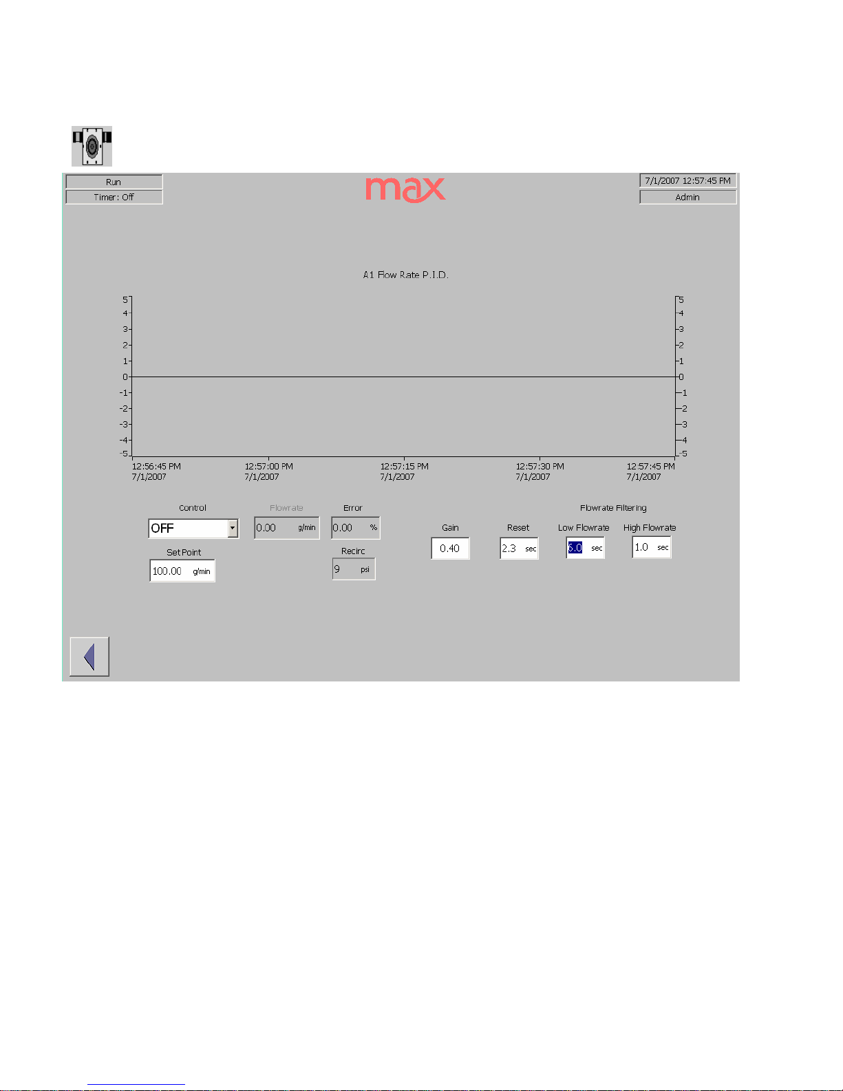
Component
PID
for
Flow
Both the flow meter signal and
the pump motor controller have P.I.D. tuning for optimum
closed loop control. These values are set at the factory and are based on the response rate of
the pumps and meters to a change in flow conditions or set point. These values should not be
adjusted
without first consulting with the Technical Service Department at Max Machinery.
Page 10
Screens
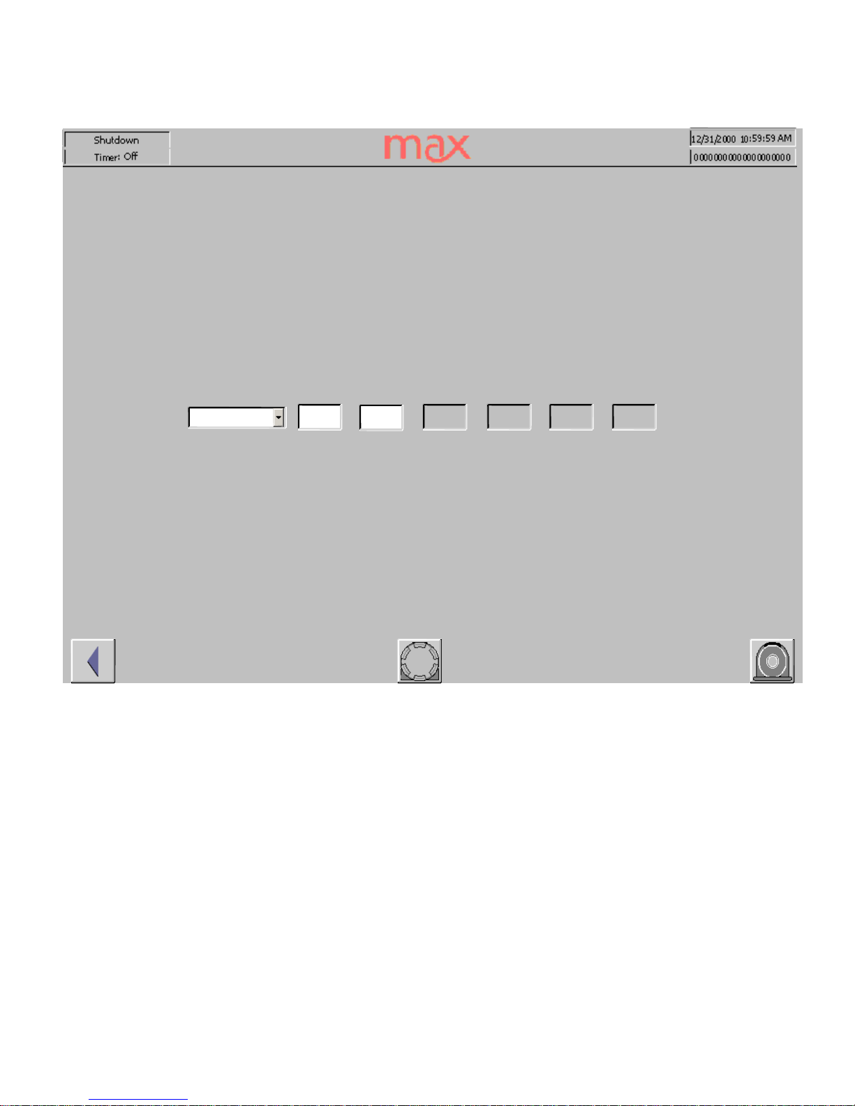
Heater
Each glycol heater system can be independently activated and be set with a Run temperature
and a standby temperature.
The control options are Off, run the pump only, or run the heater
and pump.
Additional safety feature information is also displayed: The back up safety
thermocouple, the delta temperature between the two probes and the level in the glycol
reservoir – any
of which will shut off the heater if a fault is detected.
The heater alarm configuration screen is accessed by selecting the “Beacon” button
_
_12/31/
2000 10
:59:59_
Run
_
Timer: Off
_
OFF
_
000_000_000_000_000
_
Current
_
Safety_Delta _Level
_
000
°C
°
C
°C
°C
°C
_
Control
_
%
_Run_Standby
_1_
Primary Heater
_
Temperature
Page 11
Screens
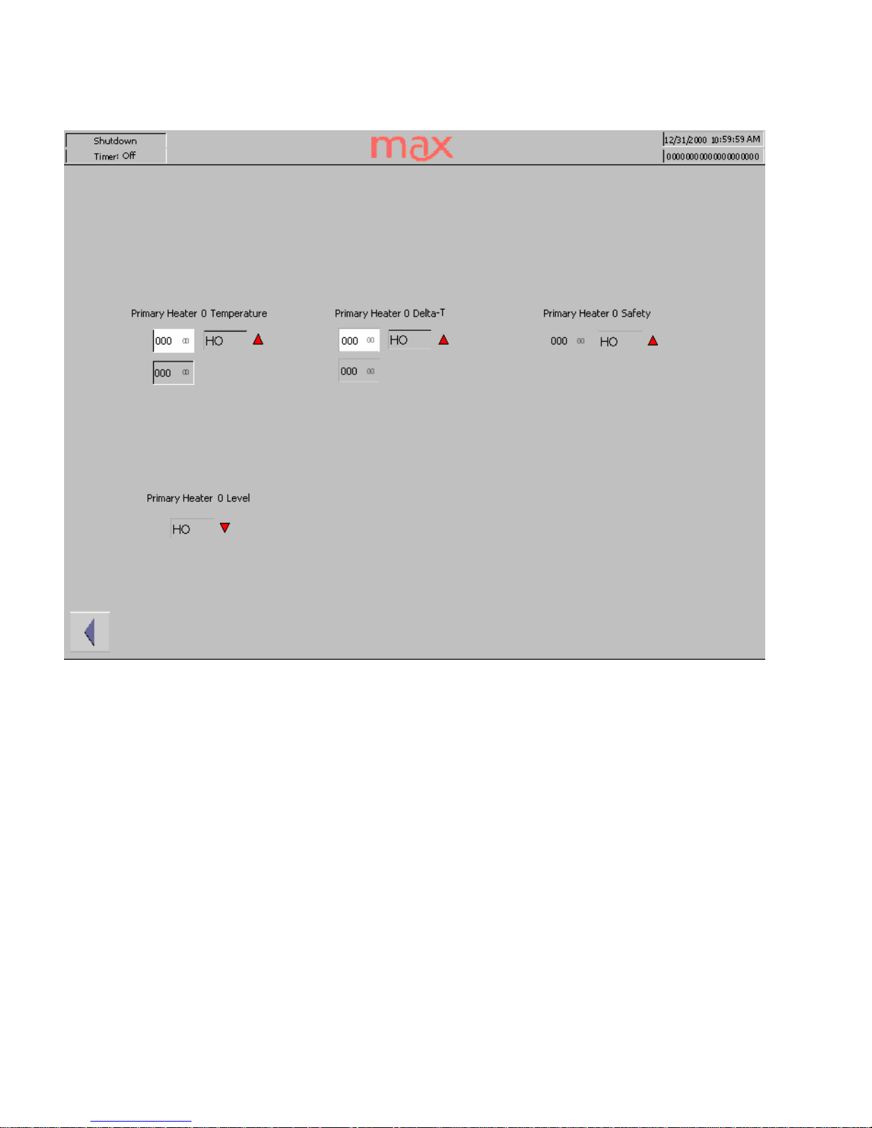
Heater Alarm
The Main Glycol heater has redundant safety settings. All alarm set poi
nts are hard coded
to shut off the heater if any parameter is out of limits. These values are set to typical
operating ranges and do not need adjustment. Lower trigger points can be programmed if
desired.
Page 12
Screens
Heat
er PID for
Temp
The glycol heater has P.I.D. tuning for optimum temperature control. These values are set
at the factory and are based on the response rate of the heater relative to the demand. These
values should not be adjusted without first consulting wit
h the Technical Service
Department at Max Machinery.
_
_12/31/
2000 10
:59:59_
Run
_
Timer: Off_Auto Reset
_
BandWidth
_
Duty Cycle
_
Current
_
000
°C
_
000
°C
_
000
°C
_
000
_
%
_00.0_00.
0
_
Run_Standby
°C
_
min
_1_
Primary Heater
_
Temperature P
.I.D
.
_
0000.0
_
Error_PID Reset
_
Reset
°C
Page 13
Screens
Chiller
The Chiller screen is where the operator can turn the Chiller on and off, set the desired
temperature and monitor current temperature.
The chiller alarm
configuration screen is accessed by selecting the “Beacon” button.
_
_12/31/
2000 10
:59:59_
Run
_
Timer: Off
_
000_000
_
Setpoint
_
Current
°C
_
Control
_
Off
°C
_
Chiller
_1_
Temperature
Page 14
Screens
Chiller
Alarm
The Chiller Alarm screen is where the operator sets the high alarm and monitors the current
temperature.
_
_12/31/
2000 10
:59:59_
Run
_
Timer: Off
_
000
°C
_
000
°C
_
Chiller
_ 1_
Temperature
Page 15
Screens
Mi
xer
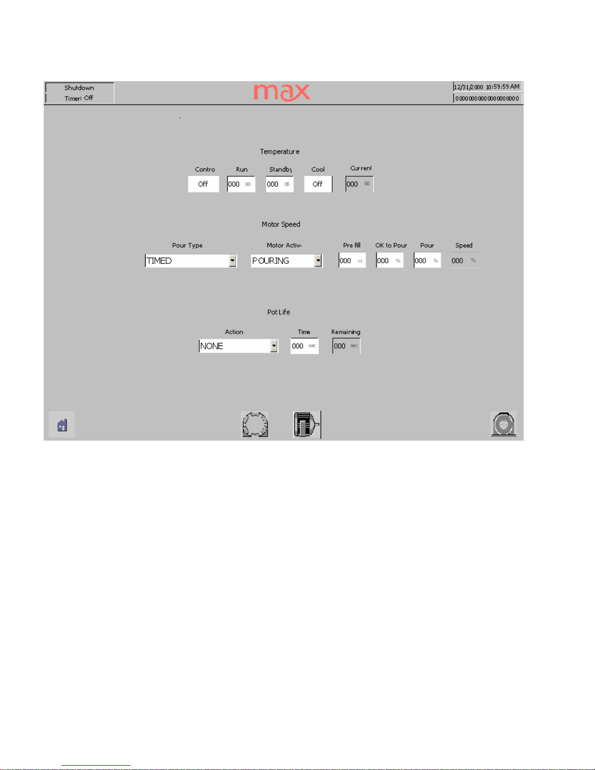
The Main mixer screen offers temperature, mixing and flushing control. The mixer zone has its
own run and standby temperature settings, the ability to activate the control function and a
direct shut off of the heating function.
The Pour Type ch
oices are timed duration, continuous pouring on “start” until the “stop” button
is pushed and momentary pouring as long as the “start” button is depressed. The mix motor
can be set to run continuously or only during the pouring interval.
To insure proper
mixing of
the chemicals, during shot operation, an up-to
-speed setting of mixer RPM will delay the pour
valves until the mixer is spinning at the minimum desired speed. The actual speed is indicated
as is the level of the mixers lubrication supply.
The p
ot life action choices are; none, warning only, automatic flushing or reci
pe purge. The
chosen action is
initiated if mixed material remains in the mix chamber longer than the selected
time. At the end of each pour, the remaining pot life will appear in
the indication window. As
a reference, the flushing solvent level is also displayed on this screen.
The center icons access the PID settings for the temperature control and the purge/flush/lube
settings.
Page 16
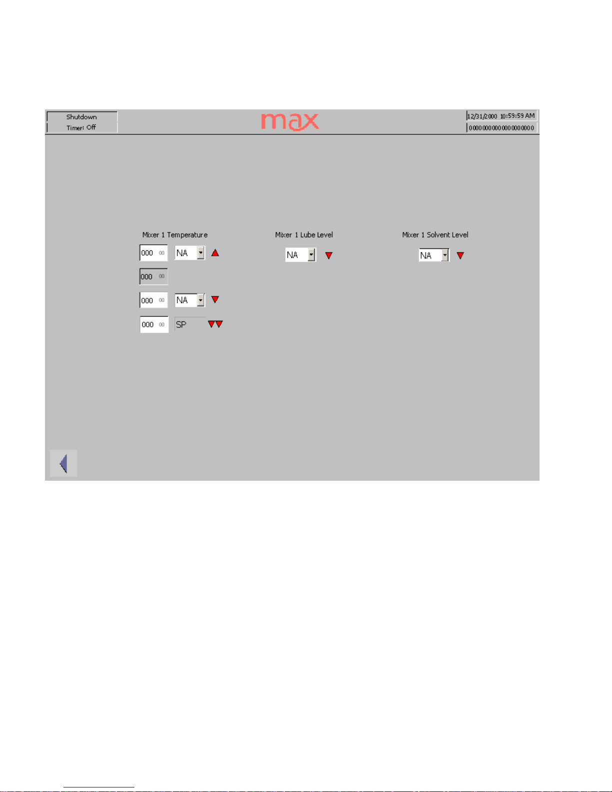
Screens
Mixer
Alarm
Available alarms and a
ctions for the Mix head are temperature, lubrication level and solvent
level.
The high and low temperature alarms can be set to either inhibit the next pour or stop the
pouring, with the low-low alarm hard coded to stop all pouring. The action available
for the
low lube and low solvent is to inhibit the next pour.
Page 17
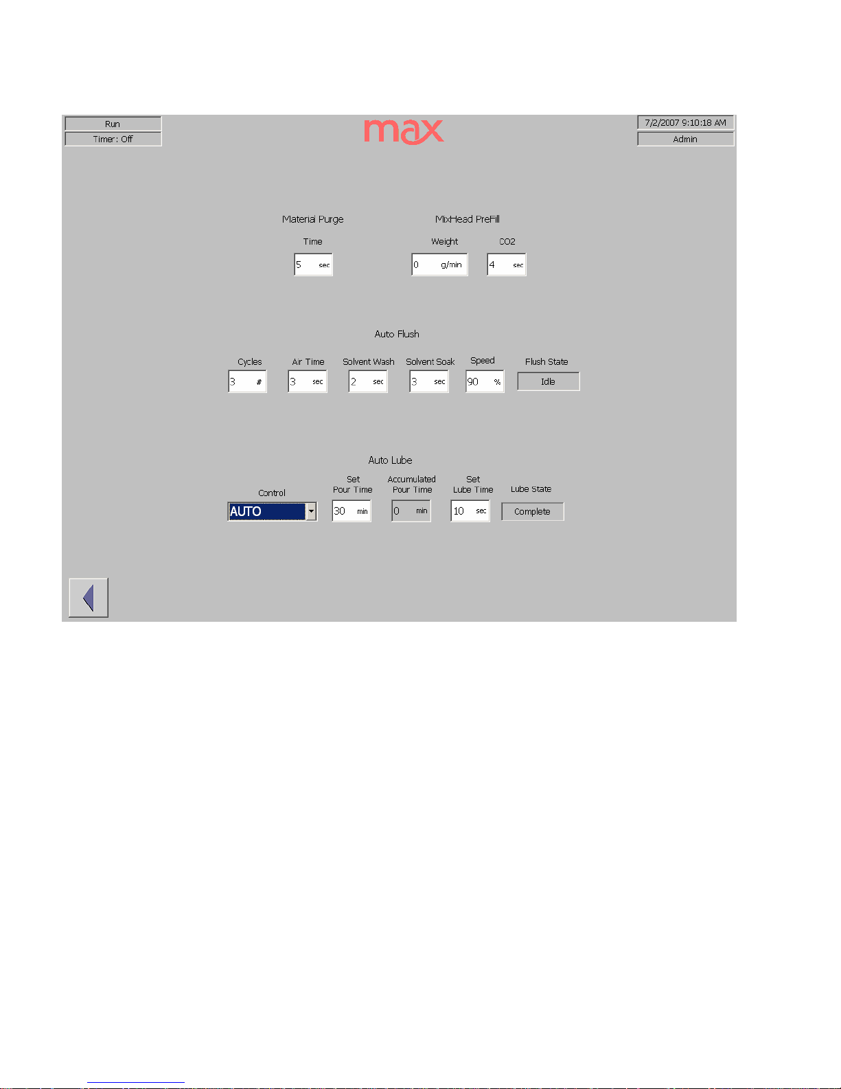
Screens
Mixer Purge/Flush/Lube
The action choices for clearing the mix head of reacting material are a recipe purge to refresh
the mix chamber or a solvent flush. The duration
of the material purge should be enough time
to displace one chamber’s worth of the current recipe. This value can be calculated by dividing
the mix chamber volume by the flow rate of the complete mixture.
The Auto Flush cycle uses a repeated sequence of
air and solvent injections separated by a high
speed rotation of the mixer
shaft
in a chamber
full
of solvent.
Depending on the reactivity of
the urethane, 2 or 3 cycles are usually sufficient. The factory settings for the air, wash and soak
durations we
re tested before shipment. If you find build up in the chamber, consult with the
Max Technical Service staff before changing these time durations.
Mix head lubrication should be set to Auto Lube. The accumulated pouring time and the
duration of the lube
flow are set at the factory. The Start/Stop controls are provided to recharge
the mixer bearing gland following a mix head servicing. Do not run the bearings without
lubricant. Use the start command until lubricant appears in the top drain line, then set the
control to Auto.
Page 18
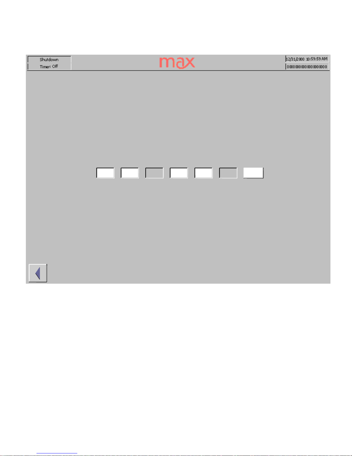
Screens
Mixer_PID_Temp
The mix head temperature zone has P.I.D. tuning for optimum temperature control. These
values are set at the factory and are based on the response rate of the mix head t
emperature to
the input of hot glycol. These values should not be adjusted without first consulting with the
Technical Service Department at Max Machinery.
_
_12/31/
2000 10
:59:59_
Run
_
Timer: Off_Current
_
BandWidth
_
Duty Cycle
_
Reset
_
000
°C
_
Run_Standby
_
000
°C
_
000
°C
_00.0_00.0_
0000
_
min_%
°C
_
Reset
_
PID Reset
_
Mixer_Temperature P
.I.D.
Page 19
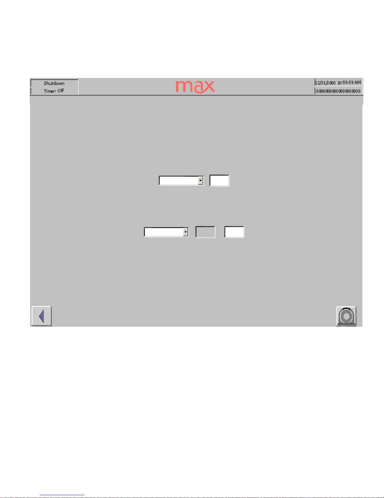
Screens
VacColdTrap
The vacuum pump oil is protected by the co
ld trap. To prevent chemical emissions from
entering the pump or work environment, the pump is interlocked to the cold trap and should not
be operated until the cold trap reaches operating temperature. The control of the Vacuum pump
is Off, immediate On
or Auto. In the Auto position the pump will start running as soon as the
cold trap reaches the Start temperature.
The control of the Cold Trap is either Off, On to chill the trap or Defrost to reverse the
compressor and melt out the accumulated vapors.
_
OFF
_
Start/Stop
_
000
°C
_
Control
_
OFF
_0
00
_
Current
_
Defrost
_
000
°C
_
Control
°C
_
Vacuum Pump
_1_
Temperature
_
Cold Trap
_1_
Temperature
Page 20
Screens
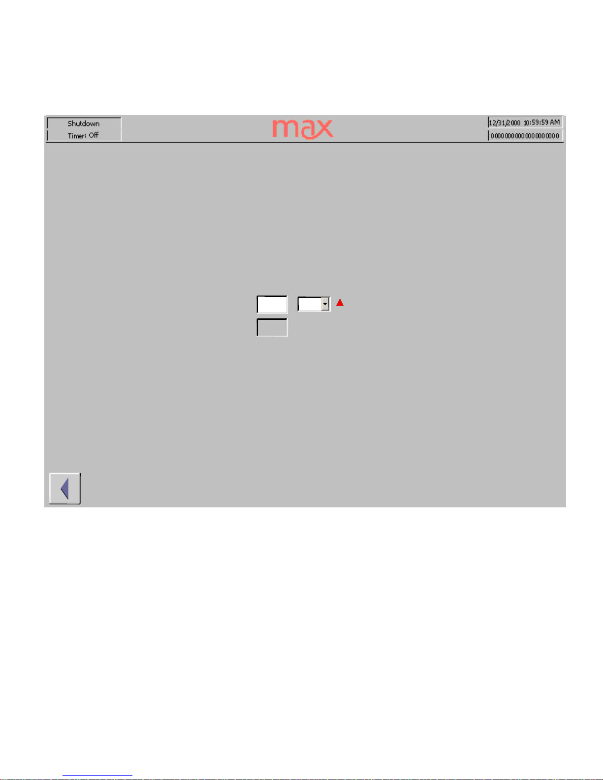
VacColdTrap_Alarm
The cold trap temperature can be alarmed as an alternative to being interlocked to the vacuum
pump. The action choice is VO, vacuum off. Setting this temperature will disable the
vacuum
p
ump, even if the pump is
set to the ON position.
_
_12/31/
2000 10
:59:59_
Run
_
Timer: Off
_
000
°C
_
000
°C
_
NA
_
Cold Tr
ap_1_
Temperature
Page 21
Screens
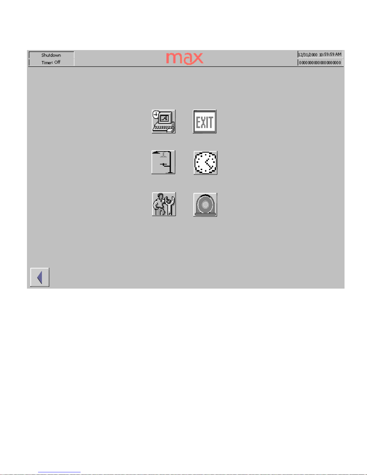
System
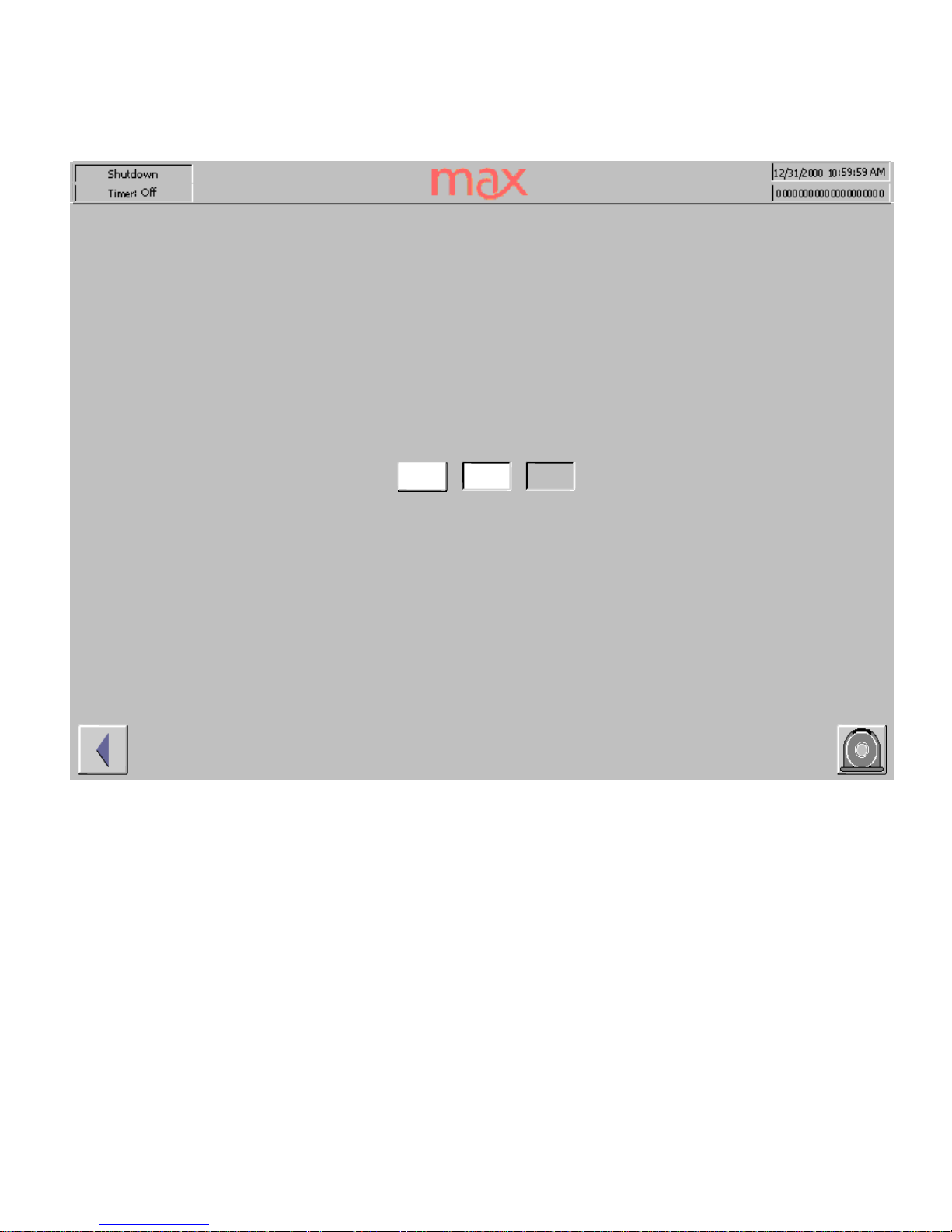
The System screen icons are a collection of maintenance functions:
Access to the Windows™
control panel, with a direct return to this screen,
EXIT
the HMI program so that you can
work in the underlying Windows™ system,
T
he shower icon numbs the touch panel long enough for it to be cleaned,
T
he 7 Day timer function,
User maintenance and
T
he Alarm
history log s
creen.
_
_12/31/
2000 10
:59:59_
Run
_
Timer: Off
Page 22
Screens
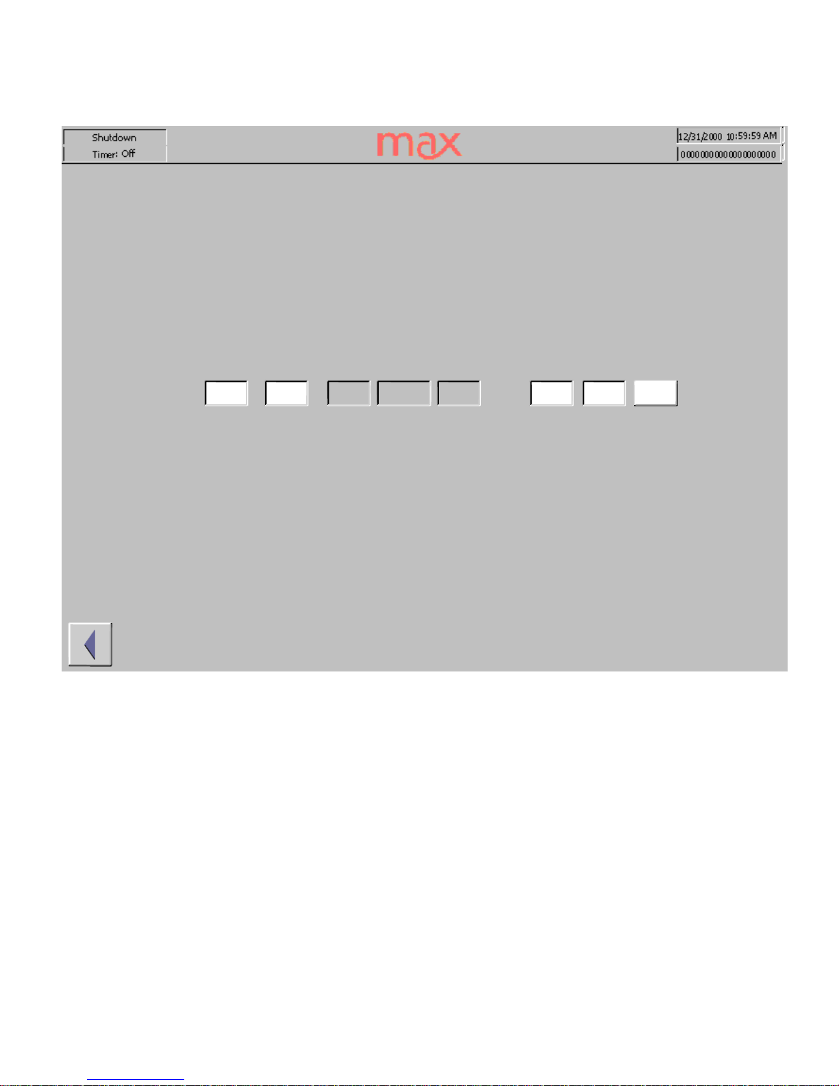
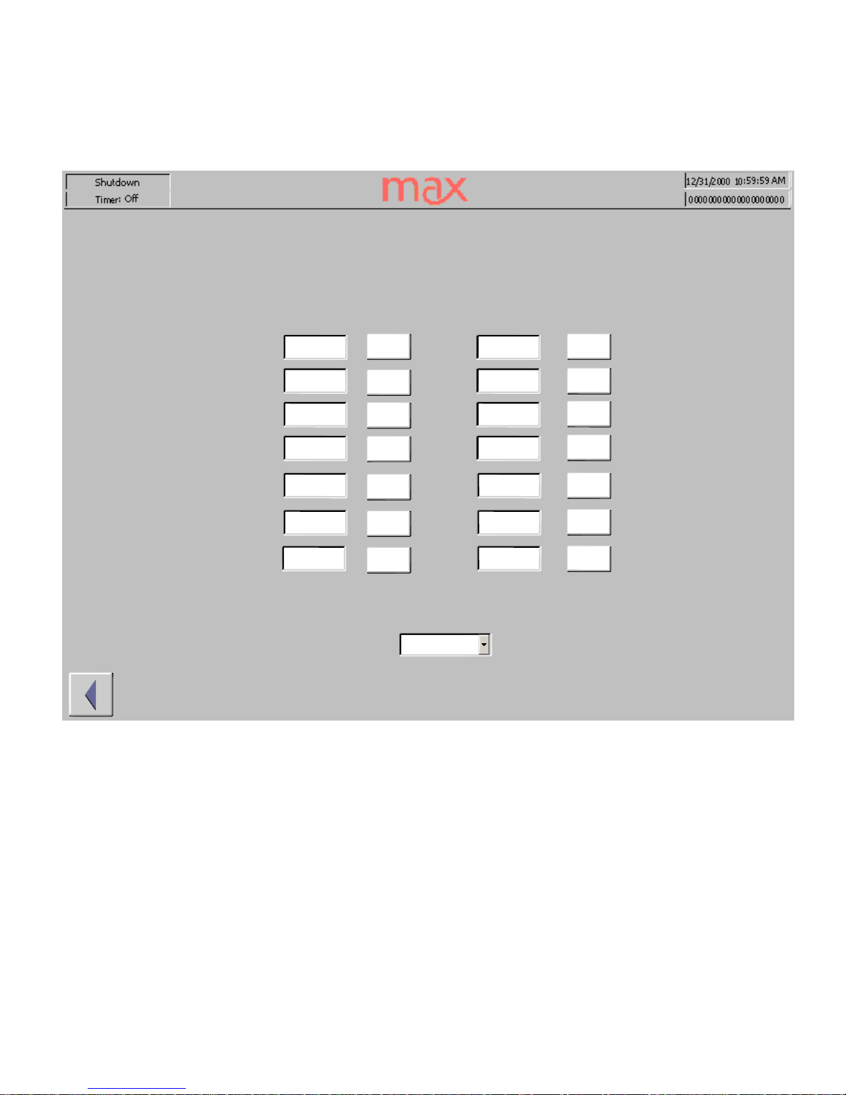
Timer
The 7 day timer program can automatically switch the temperature set points for the heater and
the temperature controlled zones. By enabling and setting the trigger points the machine can
prewarm each morning or each Monday before produc
tion begins.
The available modes are to
use the timer settings, run the machine without interference from the timer or the shutdown the
machine.
_
_12/31/
2000 10
:59:59_
Shutdown
_
Timer: Off
_
10:59:59_10:59:59_10:59:59_10:59:59_10:59:59_10:59:59_10:59:59_10:59:59_10:59:59_10:59:59_10:59:59_10:59:59_10:59:59_10:59:59
_
Day_Run_Standby
_
Enable
_
Enable
_
Monday
_
Tuesday
_
Wednesday
_
Thursday
_
Friday
_
Saturday
_
Sunday
_
Shutdown
_
Off_Off_Off_Off_Off_Off_Off_Off_Off_Off_Off_Off_Off_Off_Machine Mode
Page 23
Screens
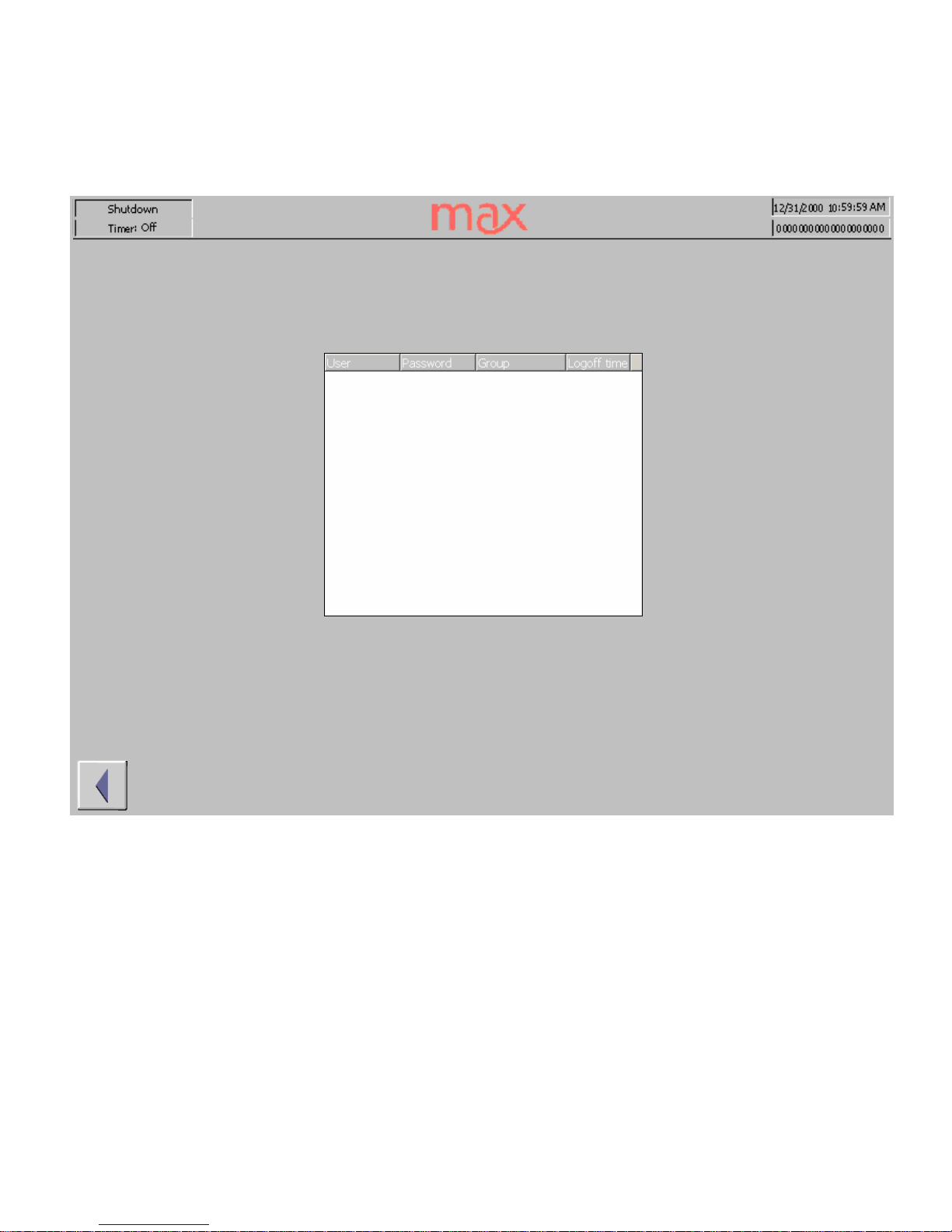
Administration
The Administration screen allows for
user creation and password maintenance. Administrator level
personnel will be shown a complete list of users and passwords. Lower level personnel will only have
access to their own password.
The available level assignments are:
User, Operator
, Engineer
and
Administrator.
Users only have screen viewing permission.
Operators can control set points, manipulate and load recipes, adjust material purge time, mixer flush
speed and change the machine mode.
Engineers add alarm set point control, flow rate and
temperature PID settings, flush time, lube time and
7 day timer control.
The Administrator has full access, user management and system control.
Some screens may contain fields that are not accessible to the currently active user
. If a lower level
user
tries to access a higher level function, they will be prompted to log in as a higher level user.
_
_12/31/
2000 10
:59:59_
Run
_
Timer: Off
Page 24
Screens
Alarm
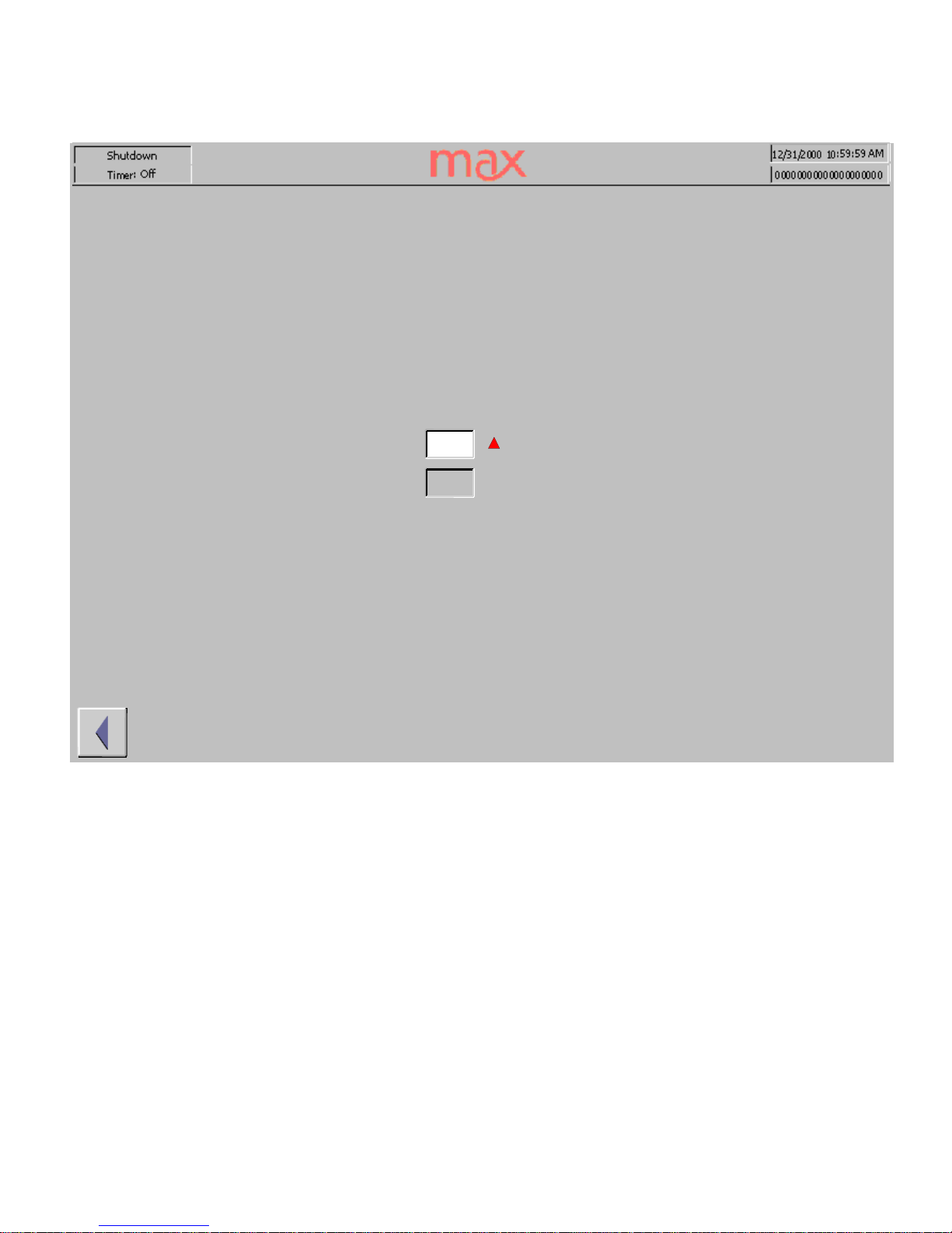
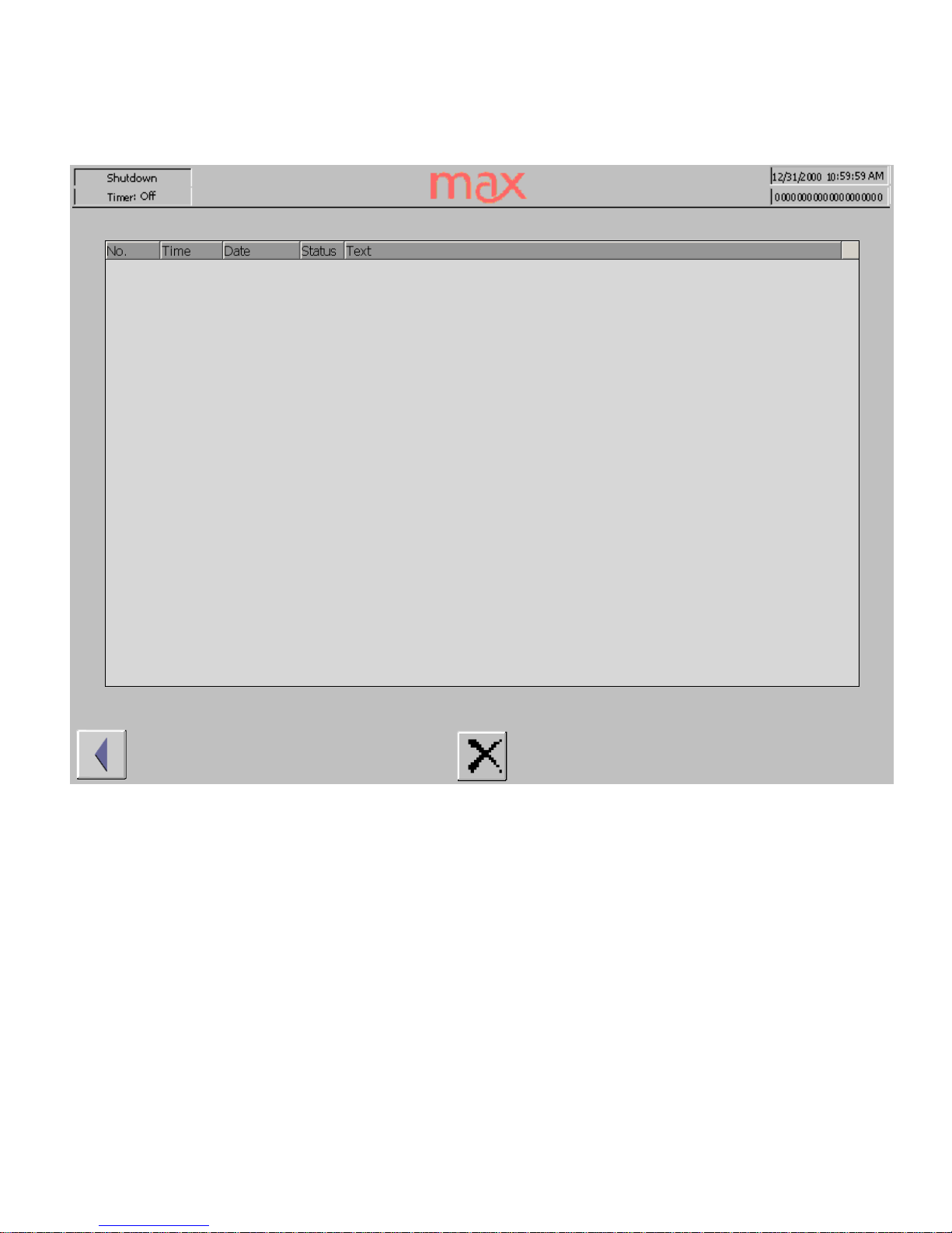
The Alarm window allows the operator to view past alarms.
This record is accessed through
the System Screen
and is different than the current alarm dialog box.
If any alarm conditions exist the operator will be notified by a floating, blue button with an
exclamation point in a triangle. Touching this button will open the alarm screen which will
display the
curr
ent
alarms
_
_12/31/
2000 10
:59:59_
Run
_
Timer: Off
Page 25

Level Access
USER TYPE RIGHTS
ADMINISTRATOR
Full Control
ENGINEER
7 Day Timer Setting
s
Component Flow Rate P.I. Set Points
Component Flow Rate Filter Set Points
Component Temperature P.I. Set Points
Component Alarm Set Points
Heater Temperature P.
I. Set Points
Heater Temperature P.I. Set Points
Heater Alarm Set Points
Mixer Temperature P.I. Set Points
Mixer Auto Flush Settings
Mixer Auto Lube Time Settings
Mixer Alarm Settings
Cold Trap Alarm Setting
System Control Panel
System Exit
OPERATOR Alarm Log Erase
Calibrati
on Settings
Chiller Control
Chiller Set Points
Clean Screen
Component Temperature control
Component Temperature set points
Component Flow rate control
Component Flow rate set points
Component Pressure mode
Component Pressure Increment/Decrement
Component Level control
Component Start/Stop Level set points
Component agitator control
Heater control
Heater Set Points
Machine Mode
Mixer Temperature Control
Mixer Motor Speed Settings
Mixer Motor Potlife Settings
Mixer Pre Fill Settings
Mixer Material Purge Time
Mixer Auto Lube Control
Pour Time
Vacuum\Cold Trap Control
Vacuum\
Cold Trap Settings
USER Administration
General Screen Access
Alarm Silence
Page 26

Backup/ Restore
Backup/Restore on memory cards
During a backup process, the operating system, application and data are copied from the
internal
Flash
memory to an external storage medium. The minimum size of the storage
medium must be 24
Mbyte.
In the case of a restore process, the content of a Flash memory
stored on an
external
storage
medium is reloaded into the internal Flash memory. Prior to this,
the MP 370’s internal Flash memory is completely cleared following confirmation.
Backup on CF card or PC card
Proceed as follows to create a backup copy of the internal Flash memory:
Step Action
1
Deactivate the write protection on the memory card, if set.
2
Depending on the target medium used, insert the memory card in the required
slot (Figure 11-1, Page 11-3).
3
Call in the Windows CE Control Panel (refer to Page 3-6) and, from
there, select the
Backup/Restore
option depicted on the right.
4
Start the Backup process by using the Backup button.
5 Confirm that any backup files wh
ich exist on the storage medium should be
completely deleted beforehand.
6
When the data has been downloaded successfully, the MP 370 issues a message.
7 Remove the memory card.
8
Activate the write protection on the memory card, if available.
9
Label
the memory card, e.g. with the date and version of the configuration
saved, and keep it in a safe place.
Note
Insert the memory card in the relevant expansion slot before starting the Backup/Restore
process:
_ PC card: Slot A (storage location \Storage Car
d\)
_ CF card: Slot B (storage location \Storage Card2
\)
Information on the memory cards which may be used is provided in
figure
3-
16, on Page
11
-3 of the
MP370 Equipment Manual 09/02 (
6AV6591-1DB10-2AB0)
Notice
A plug-in memory card is used for Backup/Re
store. If both slots are occupied when
Backup/Restore is initiated on the MP 370, the PC card (Slot A) is used first. In case of doubt,
remove the memory card not to be used from the MP 370.
Restore from CF card or PC card
Proceed as follows to restore
the content of the internal Flash memory:
Step Action
1 For security reasons, activate the write protection on the memory card, if available.
2
Depending on the storage medium used, insert the mem
ory card in the required slot
(see Figure 11-1, Page 11-3 of the MP 370 Equipment Manual).
3
Call in the Windows Control Panel and select the
Backup/Restore
option.
4 Start the restore process by clicking on the “Restore” button.
5 Confirm that the internal Flash memory and licenses should be completely del
eted.
6
After confirmation, the operating system will be reloaded and the MP 370 will
automatically restart. After restarting, the remaining data will be downloaded.
7
When the data has been downloaded successfully, the MP 370 issues a message.
8
Remo
ve the memory card.
9 Restart the MP 370.
Page 27
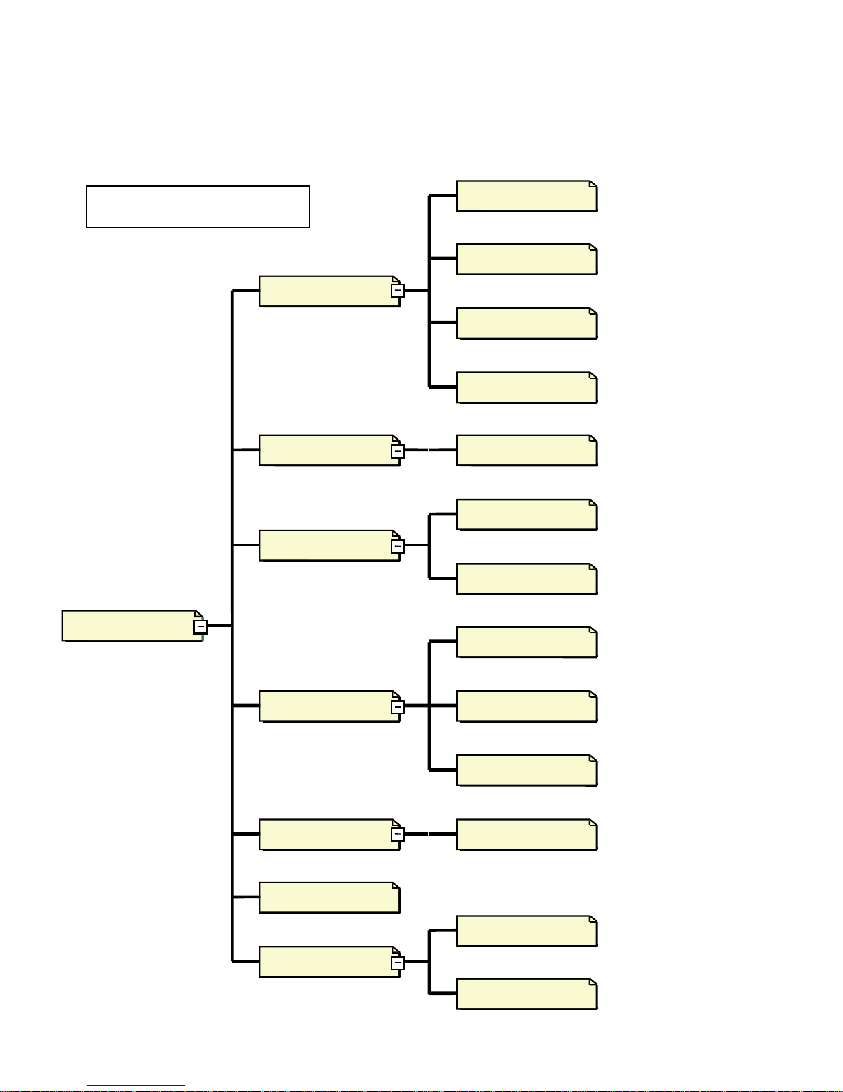
Home
Component_PID_Flow
Chiller_Alarm
Mixer_PID_Temp
Chiller
VacColdTrap_Alarm
Component_PID Temp
Heater_Alarm
Mixer_Alarm
Mixer_
Purge/Flush/Level
Administration
Alarm
Component_Alarm
Heater_PID_Temp
VacColdTrap
Heater
Timer
Calibrate
Mixer
System
Component
Screen Navigation
 Loading...