

Page 1
High Resolution, Linearized
Frequency Transmitters
Operational Manual
For Models
295, 296 and G Series Transmitters
Page 2

Table of Contents
General Description ............................................................................................................ 3
Transmitter Specications ................................................................................................ 4
Installation ............................................................................................................................ 5
High Temperature Operation ........................................................................................... 7
Temperature Limits ............................................................................................................ 8
Limited Warranty ................................................................................................................ 9
Custom Instructions for Hazardous Locations/Explosion Proof Housing:
www.maxmachinery.com/content/explosion-proof-installation-instructions
Additional technical documents regarding transmitter performance and advanced operation are available
at www.maxmachinery.com. Max Machinery, Inc. reserves the right to make changes to the product in this
instruction manual to improve performance, reliability, or manufacturability. Contact Max Machinery Inc. for
the latest available specications and performance data. Although every effort has been made to ensure
accuracy of the information in this instruction manual, Max Machinery Inc. assumes no responsibility for
inadvertent errors.
Max Machinery, Inc. 29X Frequency User Manual © Copyright 2015 Rev. 002Q1
2
Page 3
General Description
The Max frequency transmitters are designed to work with the
entire family of Max Flow Meters to provide extremely precise
ow measurement in a cost effective package. Different options
for electrical connections and temperature ranges cover a wide
range of application environments – from the laboratory to harsh
industrial processes.
This latest generation of transmitters use modern sensor
technology coupled with advanced signal processing to deliver
new levels of performance and reliability. Hall sensors are used to
detect the position of a driven magnet inside a Max Flow Meter.
Changes in position are tracked by a microprocessor, which
generates an output frequency proportional to the ow rate. Advanced signal processing provides both ne
angular resolution (0.36 degrees rotation per pulse) and rapid response (output updated every one ms).
These transmitters are typically mated to a mechanical ow meter, congured, and calibrated at the factory
as a matched set. This ensures accuracy and allows quick setup in the eld. For eld installations where the
transmitter has not been setup with a meter at the factory, an optional serial interface kit provides full access
to all conguration options and parameters.
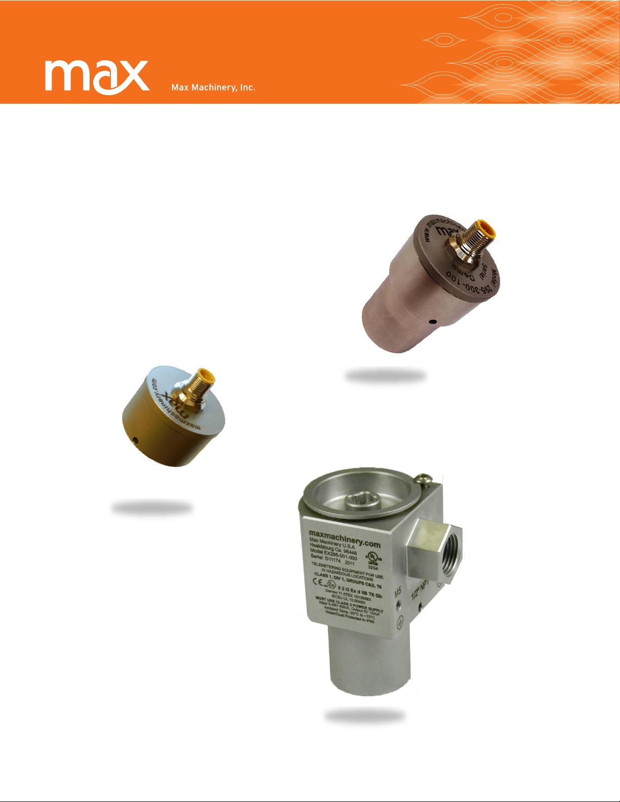
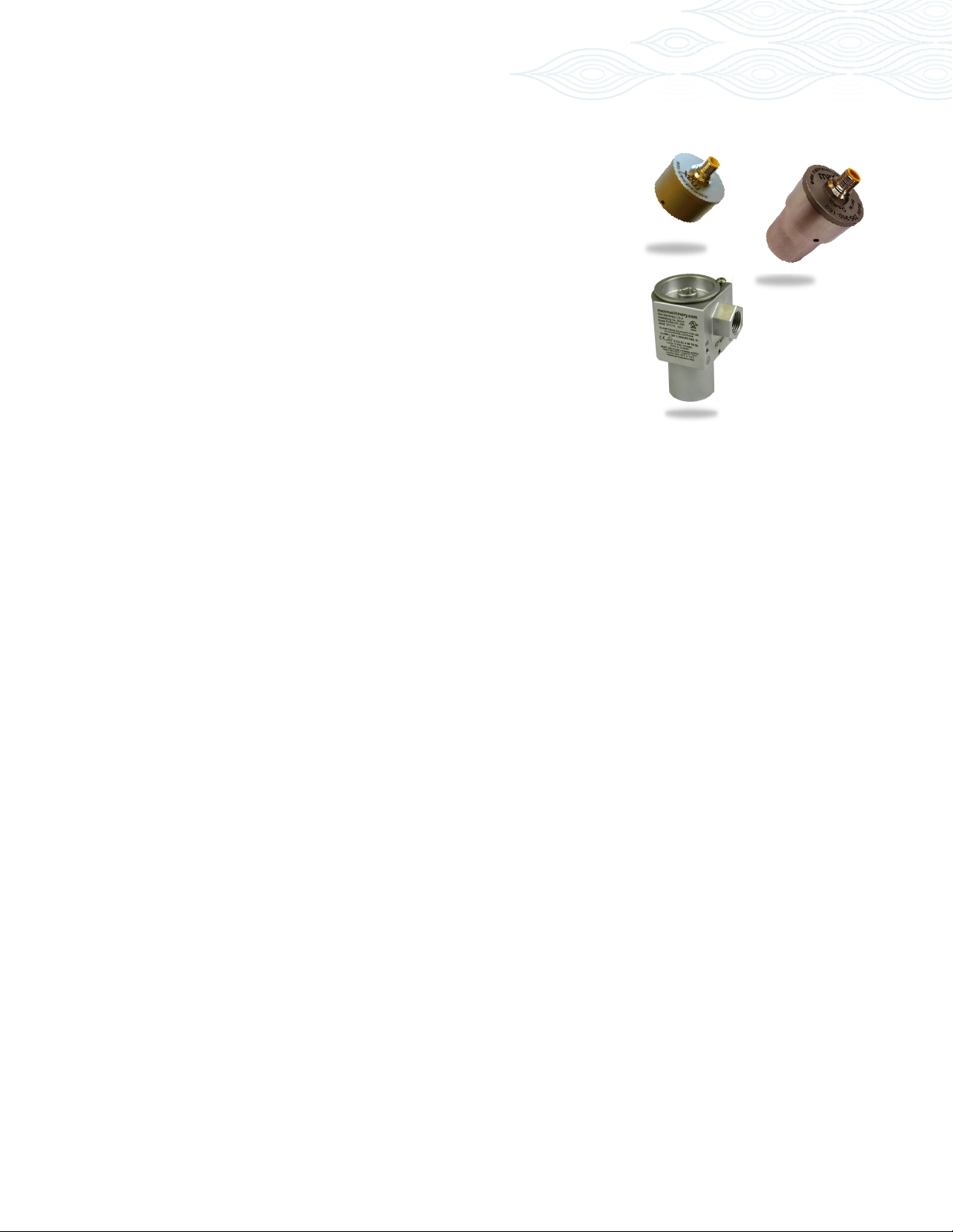
Model 296
Model 295
Ex Proof Model 295
Transmitter Features
High resolution measurement - Congured output resolution of 1 to 1000 pulses per revolution.
Linearization of up to 16 points to fully describe the ow meter’s output curve and achieve the highest
system linearity over the meter’s entire operating range.
Compensation Algorithm – Compensates for variations in Hall sensor and ow meter characteristics to
provide a stable, undamped output frequency that accurately represents the instantaneous ow rate. This
feature is factory set when the meter and transmitter are mated together. If the transmitter is changed, the
compensation can be performed via a button on the PCA.
Anti-Dither Pulse Buffer - Prevents undesired reverse pulses which can occur at very low ow rates in the
presence of vibration or hydraulic noise. If the meter reverses direction and then resumes forward rotation,
the pulse count will represent only the total forward ow. Reverse ow exceeding the pulse buffer setting will
result in an output frequency proportional to reverse ow rate. The buffer quantity can be set from 1% to
100% of a revolution.
Max Machinery, Inc. 29X Frequency User Manual © Copyright 2015 Rev. 002Q1
3
Page 4

Transmitter Specications
Supply Voltage 5-26 Vdc
Supply Current 25-30 mA typical
Output (5.0 Volt Supply) No Load 0.00 / 4.80 Volts
(TTL and CMOS compatible) 2.5K Load to Common 0.00 / 4.60 Volts
2.5K Load to +5 Volts 0.25 / 4.80 Volts
Short Circuit Current
(1)
45 mA
Output Impedance 100 Ω
Rise/Fall Time 0.2 μSec
Output Update Rate
(2)
1 ms
Min/Max Frequency 0-60 kHz
Resolution 1 - 1000 pulses/rev, Single Phase
1 - 500 pulses/rev/phase, Quadrature
Ambient Temperature Range Transmitter (Storage)–40ºC to 85ºC (–40ºF to 185ºF)
Transmitter (Operation)
(3)
–40ºC to 80ºC (–40ºF to 175ºF)
Maximum Temperature, Process Fluid
(20ºC Ambient, 5V supply) Standard Model 90ºC (195°F) – Models 295 & 296
High Temp Model – Model 296
Ultra-High Temp Model 225ºC (435°F) – Models 295 & 296
Anti-dither Range 50% of a meter revolution - unidirectional - 2% bidirectional.
(software selectable from 1-100% of 1 revolution)
Signal Filtering Software selectable from 1ms to 250ms time constant
( 1) Continuous Short Circuit is not recommended. The output current should not exceed 10 mA
(2) Events are seen as output transitions 1 ms after they occur
(3) Temperature of metered uid will affect transmitter temperature, see graph
Max Machinery, Inc. 29X Frequency User Manual © Copyright 2015 Rev. 002Q1
4
Page 5
21
4
5
3
Installation
Mechanical Installation
1. The transmitter is attached to the ow meter’s threaded magnet shield. Hand tighten only. (~ 3 ft-lb)
2. The transmitter lid has four thread paths. To realign the cable, remove the lid and rotate up to 180° and
retighten using an alternate starting point. Tighten to compress the O-ring seal.
Removal
1. Remove electrical connections 2. Unscrew transmitter, using a wrench if necessary.
Removal note: The transmitter does not need to be removed from the ow meter for any eld servicing
or adjustments. Normally, the ow meter and transmitter are shipped back to the factory for calibration
or service as a unit. If the transmitter needs to be removed from the ow meter for installation, be sure to
retighten the transmitter snugly in order to ensure proper sensor alignment.
Moisture Protection
On all models, the housing is designed as a liquid and vapor-tight enclosure. There are O—ring seals at the lid
and possibly also the base of the housing — these need to be fully seated. A properly sealed transmitter will
prevent the formation of damaging moisture inside the housing.
Turck connector Model: The connector is sealed to the lid at the factory and is ready for use.
NPT Model: To ensure a moisture-tight seal, apply appropriate sealant to the threads at installation.
Electrical Installation —
Wiring
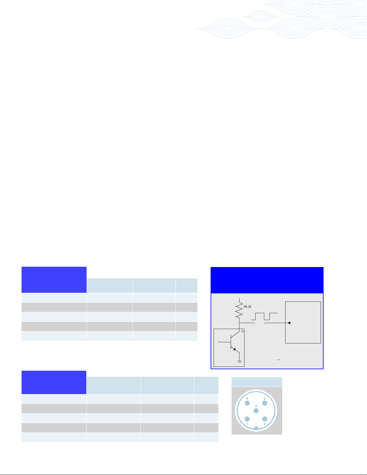
The electrical connector versions are pre-wired inside the transmitter and ready to accept a mating cable
(available from the factory). The liquid-tight, NPT models need to be wired during installation as shown in the
table below:
Frequency
Single Phase
Frequency
Case Ground Case
Single Phase
Common Com Black 4
Wiring
Power 5-26 Vdc V+
Pulse Output Ph A White 2
N/A NC Grey 5
* A current sinking device produces an output pulse which is the opposite of a
sourcing device. A positive DC voltage must be applied to the wire running between
PhA and your PLC. When the output is triggered, this voltage will be grounded to
zero volts. Note: use a 5k ohms resistor to limit the current ow in the signal line.
Frequency
Quadrature
Case Ground Case
Common Com Black 4
Power 5-26 Vdc V+
Output Phase A Ph A White 2
Output Phase B Ph B Grey 5
Max Machinery, Inc. 29X Frequency User Manual © Copyright 2015 Rev. 002Q1
Models
295 & 296
Models
295 & 296
Mating Cable
Wire Color
Blue
Brown
Mating Cable
Wire Color
Blue
Brown
Turck
Pin #
3
1
Turck
Pin #
3
1
Current Sinking* Wiring
(models 29X-6XX)
V+
V+
0V
Out
Turck Pin #2
Transmitter
Turck Connector
PLC
Digital
Input
5
Page 6

Installation continued...
LED Rotation/Output Indicators
All of the microprocessor based transmitters incorporate a LED to indicate that they are producing a pulse
output and/or detecting magnet rotation in the meter.
An alternating red/green or blue/green LED indicates that the circuit is detecting a rotating magnet and
should provide an output. Additional LED’s are present for setup, programming and troubleshooting and are
not intended for general use.
Error Codes
Flashes 8x a second to indicate that the magnet is not detected
Note: There are no selections or adjustments to be made on the circuit board. The only method of altering the
setup parameters is through the serial interface program. Contact the factory regarding P/N 294-100-050,
user interface software.
Field Compensation of transmitter
When a new transmitter is attached to a ow meter, the compensation routine should be performed to
optimize the performance of the system. This routine requires a steady ow rate which turns the meter at
between 15 and 1000 RPM. For the Model 295 and 296, the sequence is as follows:
1. Stabilize the ow rate
2. Push the compensation button on the PCA
3. The blue/green LED will change to solid blue for 6 to 8 revolutions of the meter
4. A green indicator light indicates a successful update of the compensation, a red indicator light
indicates that the previous compensation has been retained.
Max Machinery, Inc. 29X Frequency User Manual © Copyright 2015 Rev. 002Q1
6
Page 7
B
D
D
1
2
3
4
56
7
NOTE:
location installations,
customer
n ca bling a nd conduit
between
nd the re ceiving box.
receiving box must be
Rb
Com
Ra
C
Case
5v
V+
B
For Pulse
PhB -- Grey
PhA -- White
Com
PhA/Sig
Ret -- White
Sig -- Grey
For Analog
Case
Ph B/ Re t
A
8/23/11
DATE
33A HEALDSBURG AVE
HEALDSBURG, CA 95448
MAX MACHINERY
TM
bsnyder
DESIGNER
DESCRIPTION
-1
1
REV
OF
1
1
SHEET
1:1
SCALE
D
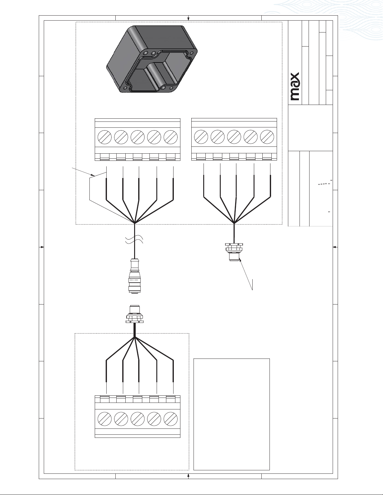
Wiring Diagram for Remote 295/296 Xmtrs
DRAWING
SIZE
2
*** COPYRIGHT ***
LIMITED PURPOSES. IT MAY NOT BE
MAX MACHINERY INC. AND CONTAINS
THIS DOCUMENT IS THE PROPERTY OF
Receiver Box Wiring
Shield
Brown
G re y
shield with shrink wrap or tape
and connect to Brown/Com.
receiver box end. MUST cover
Shield is only connected at the
Black
White
Blue
Brown
***
Bla c k
Blue
***
Use Standard
Cable for
Connection to
Instrumentation
AND THEN ONLY BY WAY OF LOAN FOR
CONFIDENTIAL AND TRADE SECRET DATA
AS AUTHORIZED BY MAX MACHINERY INC.
OF MAX MACHINERY INC. THIS DOCUMENT
REPRODUCED IN WHOLE OR IN PART AND
MAY BE TRANSFERRED FROM THE CUSTODY
OR CONTROL OF MAX MACHINERY INC. ONLY
MACHINED
FINISH
MATERIAL
MAX MACHINERY INC.
NEED FOR SUCH USE OR DISCLOSURE
INC. UPON REQUEST AND IN ALL EVENTS
MUST BE RETURNED TO MAX MACHINERY
CONSISTENT WITH THE PURPOSE OF THE
UPON COMPLETIONS OF PURPOSE OF THE
LOAN. NEITHER THIS DOCUMENT NOR THE
OR DISCLOSED TO PERSONS NOT HAVING A
INFORMATION IT CONTAINS MAY BE USED BY
LOAN WITHOUT PRIOR WRITTEN CONSENT OF
FINISH 64
MAX SURFACE
TOLERANCES
STANDARD
FOR FEATURES WITHOUT
3
TO .010 - .015
3RD ANGLE PROJ.
DRAWN IN INCHES
BREAK ALL EDGES
1°
.0005
1/64
.003
.010
.05
ANGULAR
FRACT.
.XXXX
.X
.XXX
.XX
.010
4
THESE FEATURES IS
UNLESS OTHERWISE
NOTED, TOLERANCE ON
DIMENSIONS, REFER TO
ELECTRONIC MODEL FILE.
5
Remote to Receiver
Pigtail Connector from
6
G re y
Rb
White
Ra
Brown
8
Meter Side Wiring
Com
Max Machinery, Inc. 29X Frequency User Manual © Copyright 2015 Rev. 002Q1
Black
5v
C
Blue
must supp ly the ir
the me ter side
For ha za rd o us
Case
ow
a
in a SAFE zo n e!
The
7
8
A
7
Page 8
High Temperature Operation
Operation Above 65°C (150°F)
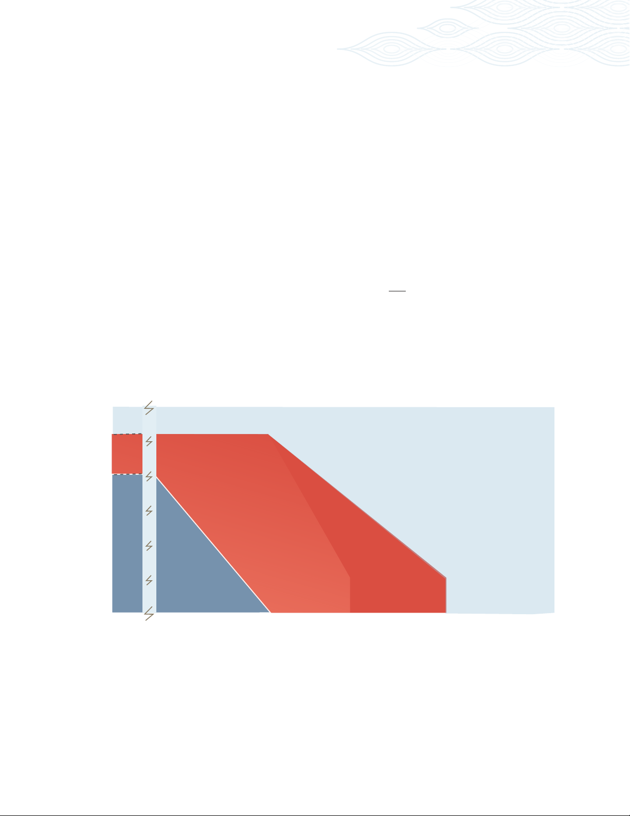
The operating limit of the meter/transmitter is a function of both the ambient and the metered uid
temperature, as shown in the following graphs. Although the electronic components are rated to 80°C
(175°F), additional heat can be conducted from the ow meter into the transmitter housing requiring a lower
ambient temperature limit for high uid temperatures.
To prolong the life of the transmitter and reduce the risk of component related failures over time, high
ambient temperatures >65°C (150°F) should be avoided if possible. It is a good idea to locate the transmitter
away from hot spots such as steam pipes, ovens and heaters. When working with elevated uid temperatures
>65°C (150°F), insulating the ow meter is required to reduce heating of the electronics by convection of hot
air off of the meter (especially for larger meters). The upper temperature limits shown in the curves rely on
ambient convection to remove heat from the transmitter housing, cooling the electronics. For this reason,
if operating near the upper temperature limit, the transmitter should not be insulated. At these elevated
temperatures, the transmitter will be very hot — exercise appropriate caution.
Temperature Limits
Model 29X Transmitter Series
120
110
100
80
60
295 & 296 296 295 & 296
Standard
50
Ambient Temperature °C
40
20
0
-25
High
temperature
2 part pickup
100
Process Temperature °C
Ultra High
temperature
2 part pickup
150 200
225
250
300
Max Machinery, Inc. 29X Frequency User Manual © Copyright 2015 Rev. 002Q1
8
Page 9

Limited Warranty
The Seller warrants all equipment manufactured by it to be free from defects in materials and workmanship in normal
service for a period of twelve (12) months from the date of shipment. When given prompt notice by the Purchaser, the
Seller shall, in complete fulllment of its liabilities under this warranty, correct by repair or replacement any such defect
without charge F.O.B. the Seller’s factory, with the following stipulations:
1. Product is not to be returned to Seller without rst obtaining a product-evaluation quote number from our
Customer Service Department at (707) 433-2662.
2. Seller assumes no liability for charges incurred for repairing, removal or replacement, or for repairs made
outside of its factory.
3. Seller reserves the right to inspect products claimed defective under warranty and is the nal authority on the
validity of the warranty claim. (Actions that void the warranty include, but are not limited to, disassembly of the
meter, failure to install recommended ltration or passing incompatible liquids through the meter.)
IT IS EXPRESSLY AGREED THAT THIS WARRANTY OR ANY OTHER WARRANTY STATED OR REFERRED TO ON THE
SALES ORDER DOCUMENT IS EXCLUSIVE AND IN LIEU OF ANY OTHER WARRANTY OF MERCHANTABILITY, FITNESS OF
PURPOSE, OR ANY OTHER WARRANTY OF QUALITY, EXPRESS OR IMPLIED.
Max Machinery, Inc. 29X Frequency User Manual © Copyright 2015 Rev. 002Q1
9
 Loading...