

COMMISSIONING, OPERATING AND MAINTENANCE MANUAL
MODEL: MAXLOGIC SERIES
SUB MODEL: CONVENTIONAL SYSTEM
FIRE ALARM CONTROL PANEL

CONTENTS
No Section Page
Introduction
Warning
Mounting
Inputs
Outputs
Controls
Indicators
Fuses
Panel conditions
Menu Modes
Technical Specifications
Santral Models
Accessories and Options
Annex - A : Panel Wiring Diagram
Annex - B : Panel Dimensions
Annex - C1 : Panel Serigraphy
Annex - C2 : Panel Serigraphy
Annex - C3 : Panel Serigraphy
Annex - C4 : Panel Serigraphy
1
2
3
4
5
6
7
8
9
10
11
12
13
Annex
Page 2/16KK-642.042 Rev.No:0 01.11.12 ML-221XX User Manual
3
3
4
4
4
5
5
6
6
7
7
8
8
11
12
13
14
15
16

1- INTRODUCTION
2- WARNINGS
Producer-manufacturer or importer firms’ title, address, and telephone number
Manufacturer Firm:
MAVILI ELEKTRONIK TICARET VE SANAYI A.S.
SERIFALI MAHALLESI, KUTUP SOKAK NO: 27/1-2-4 UMRANIYE - ISTANBUL - TURKEY
TEL: +90 216 466 45 05 - +90 216 466 45 10
Service stations’ communication information that related spare parts have been provided
Authorized Services:
MAVILI ELEKTRONIK TICARET VE SANAYI A.S.
SERIFALI MAHALLESI, KUTUP SOKAK NO: 27/1-2-4 UMRANIYE - ISTANBUL - TURKEY
TEL: +90 216 466 45 05 - +90 216 466 45 10
TEKSIS TEKNIK ELEKTRONIK SIS. TIC. VE SAN. LTD. STI.
SERIFALI MAHALLESI, KUTUP SOKAK NO: 27/3 UMRANIYE - ISTANBUL - TURKEY
TEL: +90 216 313 60 60 - +90 216 313 47 49
Expected operation life which has been determined and announced by related ministry.
This device’s expected operation life is 7 years.
Maxlogic ML-221XX series conventional fire alarm control panel has, 2, 4, 8, 12 ve 16 zones (detection circuits) according to model
with 24V DC operating voltage. Power supply of panel has an automatic battery charger and charger control circuit. Fire and fault
conditions for each zone are indicated by individual LEDs on the fascia. Zone circuits and sounder outputs are continuously
supervised for open and short circuits. Zones can be put into Test or Disable Mode.
The panel has one sounder output, fire and fault relay outputs and one auxiliary power supply output for energising external
equipment.
The control unit contains static-sensitive high quality electronic control equipment. Do not use the panel before reading this
manual.
The subjects that should be noticed during handling and transportation
• This product should be stored as packed on indoor areas.
• Storing ambient temperature should be (-30°C) to (+60°C), and relative humidity should not be exceed %95 as uncondensed.
• Product’s transportation can be performed as packed by train, road, ship and air vehicles.
• Transportation ambient temperature should be (-30°C) to (+60°C).
• The boxes that contain this device should be placed safely and properly to prevent any damage by each other.
Page 3/16KK-642.042 Rev.No:0 01.11.12 ML-221XX User Manual
Warnings that may dangerous or harm people’s or environment’s health during operation
• MP-8 Panel’s main supplied power is 230V AC. Do not make connections under power to the danger of electric shock
• Ground connection must be made of the panel definitely.
• Please consider there are some electronic components inside this device, so do not clean this device by dry rag etc
The subjects related with maintenance, fixing or device’s cleaning operations that the customer/user has been done on their own
The following points should be checked each working day by user. Observed malfunctions should be registered, and corrective
activities which were related with these problems should be performed as soon as possible.
• If device shows its tranquility condition or if there is a deviation from tranquility condition and authorized service has been
informed if needed.
• When required operations have been performed to alarms which have been registered after last operation day.
• If disable, experiment or silence operations have been occurred and system turned back to normal operation mode.

3- MOUNTING
4- INPUTS
5.1 SOUNDER OUTPUT
The panel has two supervised sounder output rated 0.5А 24V DC. Overloading the output will cause a sounder output fault and fuse
activation. A 2x1.5 mm2 cable must be used as a sounder circuit. 10кΩ resistor, located on sounder output from factory default is
used as end-of-line element.
5.2 AUXILIARY POWER SUPPLY OUTPUT
The panel is equipped with an auxiliary 0.5А 24V DC power supply output. The output is used for energising external devices such
as telephone dialler or gas detector. Connecting an external device with improper voltage requirement or overloading the output
will cause device malfunction or output fault. The output provides continuous power supply. In case of mains power supply failure,
the batteries provide power supply to the output.
5.3 RELAY OUTPUTS
The panel has two relay outputs with volt free changeover contacts rated 1A 30V DC, NC and NO. If a relay output would be used
in an application requiring continuous high current - even below the rated values - an appropriate terminal should be used between
the device and the relay output.
5- OUTPUTS
Page 4/16KK-642.042 Rev.No:0 01.11.12 ML-221XX User Manual
The chosen site for the mounting of the panel must be clean, dry and not subject to shock or vibration. The panel must not be
mounted near to sources of excessive heat or cold (see the specifications). Mark the position of the fixing holes according to the
respective Annex, ensuring that the wall is flat at the chosen location. Screws or bolts of a minimum of 4mm diameter must be used
to mount the cabinet in all mounting positions. Panel cable entries from back and top of the panel are available for easy mounting.
Drill and plug the wall then fix the cabinet using all fixing points. Open the panel front cover using the key provided.
4.1 MAINS POWER SUPPLY
The system is designed to operate with 220V AC 50Hz. Earth connections must be made to earth terminal and earth resistor must
be less than 10Ω. The mains supply of the panel must be via an independent self-resetting fuse rated 6A 220V AC. This fuse must
be separate from the other fuses and a caution note should be written such as “ATTENTION! FIRE ALARM CONTROL PANEL’S FUSE.
DO NOT REMOVE” to ensure safe operation of the panel. Recommended cable types for mains power supply are 3x2.5 NYM or 3x2.5
NYA. Do not connect or disconnect detection circuits, mains supply input and PCB connections while the panel is energised to avoid
an electric shock.
4.2 BATTERIES
Batteries provide continuity of operation during a failure of the mains power supply. The power supply has an automatic battery
charger circuit, so there is no need for an external charging unit. The panel uses two units of 12V DC 7Ah dry type batteries.
4.3 ZONES
Zone circuits provide supply to detectors and manual call points, and conduct fire, short circuit and open circuit signals. Please refer
to the respective Annex for connection scheme. Each zone is capable of hosting up to 20 fire detectors and infinite number of
manual call points. The characteristics of the cable is dependant on the length of the circuit: for a circuit of 0-500 meter long, use
1x2x0.8+0.8J-Y(st)Y cable, for a circuit of 500-1500 meter long - 1x2x1.5+1.5J-Y(st)Y. A 6.8kΩ resistor must be connected to
unused circuits and after the last device on the circuit as an end-of-line element.

6- CONTROLS
7- INDICATORS
Button Control key
To use the buttons, the Button Control key must be positioned to the Enable position. Enabling the buttons will cause the buzzer to
sound intermittently every 10sec.
Silence / Sound Alarm button
Pressing the button in normal condition will cause activation of the sounder output, the buzzer and the fire relay output as well as
illuminating of general FIRE LED.
Silence Buzzer button
Pressing the button will silence the buzzer.
Lamp Test button
Pressing the button will activate all LEDs and the buzzer thus testing their proper functioning.
Reset button
Pressing the button will reset fire and fault conditions as well as fire and fault relay outputs to return the panel to normal condition.
Processor Reset buton
Pressing the button will reset system.
7.1 Front case indicators
Power On
Continuous illumination indicates that the panel is energised. Flashing indicates fault in mains or battery power supply.
General Fault
Illumination indicates any fault condition. This would typically be:
- Mains power supply or battery voltage is low,
- Leak from ‘+’ or ‘-‘ wire to earth,
- Open or short circuit on the sounder circuit,
- Open or short circuit on the zone circuits,
- Overloading of the auxiliary power supply output.
Power Fault
Illumination indicates power supply fault condition.
Earth Fault
Illumination indicates current leakage from ‘+’ or ‘-‘ contacts to earth.
Alarm / Buzzer Silenced
Flashing indicates that sounder output or both sounder output and buzzer are silenced. Continuous illumination indicates that only
the buzzer is silenced.
Page 5/16KK-642.042 Rev.No:0 01.11.12 ML-221XX User Manual
5.3.1 FIRE RELAY:
The fire relay activates on fire condition. The output is returned to its initial position by pressing Reset button provided no fire
condition is available. The fire relay is normally not energised.
5.3.2 FAULT RELAY:
The fault relay activates on fault condition. The output returns to its initial position automatically as soon as fault condition ends.
Fault relay is normally energised; this enables conveying a fault signal to a remote control unit when the panel goes out of power
supply.

9- PANEL CONDITIONS
Page 6/16KK-642.042 Rev.No:0 01.11.12 ML-221XX User Manual
Disable
Flashing indicates any disablement condition.
Sounder Fault
Illumination indicates open or short circuit on the sounder output.
Zonal faults
Illumination indicates;
Short circuit on the zone cabling,
Open circuit,
Connection problems between detector and base,
End of line resistor wiring problems
8- FUSES
SOUNDER OUTPUT FUSE (F2,F3)
The self-resetting fuse activates on 0.5А current overload on the sounder circuit. The overloading would typically be caused by
connection of too many devices to the output.
BATTERY FUSE (F4)
The self-resetting fuse activates on 0.5А overload or a short circuit on battery inputs.
AUXILIARY POWER SUPPLY OUTPUT FUSE (F1)
The self-resetting fuse activates on 0.5А overload on the auxiliary power supply output. The fuse activation causes illumination of
the General Fault LED and buzzer sounding.
MAINS FUSE
The glass type fuse activates on 5А current overload, a short circuit or exceeding 230V AC on mains supply input. On activation of
the mains fuse the batteries energise the panel.
9.1 NORMAL
In normal condition, only the Power On LED should illuminate.
9.2 FIRE
Upon receiving of a fire signal from detector or manual call point, respective zonal FIRE LED(s) illuminate(s) with the main FIRE
LED. The sounder output, the buzzer and the fire relay output activate. In this condition, first of all, position the Button Control key
to Enable and press the Silence / Sound Alarm button. The sounder output will silence. The zone, from which the fire alarm signal
has been received, should be checked immediately. On fire signal confirmation, press the Silence / Sound Alarm button to reactivate
the sounder output. If there is no fire, eliminate the cause of the false alarm and press the Reset button to return the system to
normal condition.
9.3 FAULT
Upon receiving any fault signal, General Fault LED illuminates, the buzzer sounds and the fault relay activates. Respective zonal
Fault LED illuminates if the signal is received from specific zone. The system returns to normal condition automatically as soon as
fault condition ends.

10.1. TEST MODE
In Test Mode, manually initiated fire condition is automatically reset in a few seconds by the panel. The Test Mode causes
continuous illumination of the respective zonal Fault LED. Steps taken for entering and quitting the Test Mode are as follows:
- Set the Button Control key to Enable position. The buzzer will sound once.
- Press the Silence Buzzer button, then, keeping the button pressed, press the Silence / Sound Alarm button till Alarm / Buzzer
Silenced, FIRE and GENERAL FAULT LEDs start to illuminate.
This will take about 5 seconds.
- Zone 1 FAULT LED will start to illuminate. Move to the zone required by pressing the Silence / Sound Alarm button.
- After the zone has been selected, press the Reset button till Alarm / Buzzer Silenced, FIRE and General Fault LEDs start to
illuminate again. Continuous illumination of the zonal FAULT LED will indicate that the zone is in Test Mode.
- Set the Button Control key to Disable position. To free the zone from the Test Mode, follow the above steps once again. On
successful quit from the Test Mode, the respective zonal FAULT LED will turn off.
10.2. DISABLE MODE
In Disable Mode, a fire or fault signal from the disabled zone does not cause the panel to signal fire of fault condition. The Disable
Mode causes flashing of the respective zonal FAULT LED. Steps taken for entering and quitting the Disable Mode are as follows:
- Set the Button Control key to Enable position. The buzzer will sound once.
- Press the Silence Buzzer button, then, keeping the button pressed, press the Reset button till Alarm / Buzzer Silenced, FIRE and
General Fault LEDs start to illuminate. This will take about 5 seconds.
- Zone 1 FAULT LED will start to flash. Move to the zone required by pressing the Reset button.
- After the zone has been selected, press the Silence / Sound Alarm button till Alarm / Buzzer Silenced, FIRE and General Fault LEDs
start to illuminate again. Flashing of the zonal FAULT LED will indicate that the zone is in Disable Mode.
- Set the Button Control key to Disable position.
To free the zone from the Disable Mode, follow the above steps once again. On successful quit from the Disable Mode, the
respective zonal FAULT LED will turn off.
Zone Capacity :
Sounder Output :
Auxilary Power Output :
Fault Relay :
Fire Relay :
Fire Zone End of Line Resistor :
Sounder Circuit End of Line Resistor:
Main Supply :
Operating Voltage :
Power Supply :
Battery :
Construction:
Surface :
Mounting :
Standard Colour :
Operating ambient temperature :
Operating ambient humidity:
Size:
2, 4, 6, 8, 16
24 V DC 500 mA automatic fuse protect
24 V DC 500 automatic fuse protect
30 V DC 1A dry contact
30 V DC 1A dry contact
6,8 kΩ
10 kΩ
230 V AC 50 Hz (2A glass fuse protected)
24 V DC
1,5A
2 x 12 V DC 7 Ah
Cabinet; 1,2 mm fascia, 1,5 mm sheet steel
Epoxy
Surface
Grey metal box, white panel face
(-10°C) - (+55°C)
%0 - 95
400 x 300 x 100 mm
10- MENU MODES
11- TECHNICAL SPECIFICATION
Page 7/16KK-642.042 Rev.No:0 01.11.12 ML-221XX User Manual
12- SANTRAL MODELS
13 - ACCESSORIES AND OPTIONS
Product Code
ML-22102
ML-22104
ML-22108
ML-22116
MLY-2210
MLY-2211
MLY-2212
MLY-2213
MLY-2214
MLY-2215
MLY-2216
MLY-2217
MLY-2218
8 way Relay card
8 way Sounder card
Network card
Memory card
Network & Memory card
4 way relay card
4 way sounder card
2 way relay card
2 way sounder card
2
4
8
16
Zone Capacity
Product Code Product Name
Page 8/16KK-642.042 Rev.No:0 01.11.12 ML-221XX User Manual
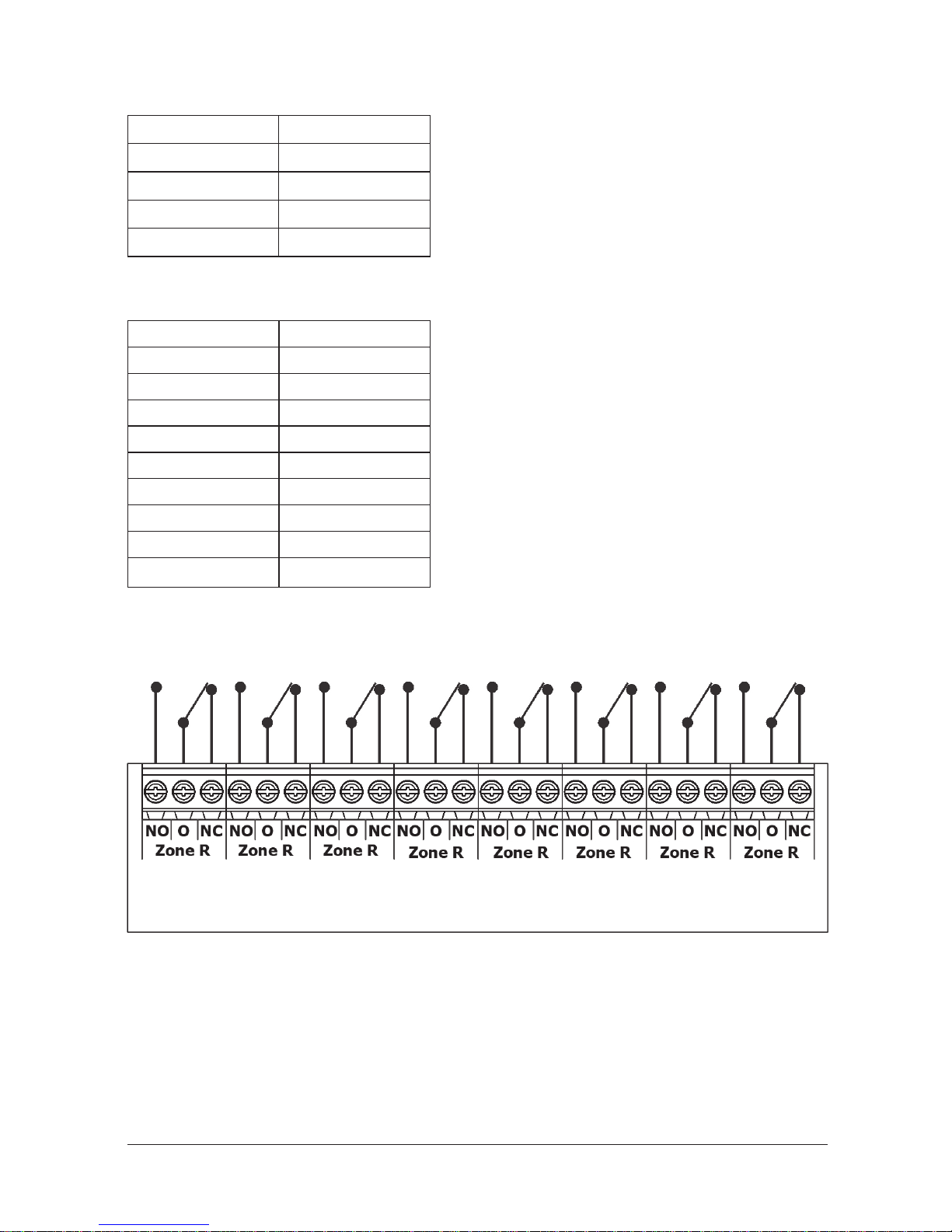
13.1 - 8 way Relay card (MLY-2210)
• Relay module provides zonal relay output for Maxlogic ML-221XX series conventional panels.
• Relay outputs 30 V DC 1A.
8 way Relay card (MLY-2210) Wiring Diagram

Page 9/16KK-642.042 Rev.No:0 01.11.12 ML-221XX User Manual
13.2 - 8 way Sounder card (MLY-2211)
• Sounder module provides zonal sounder output for Maxlogic ML-221XX series conventional panels.
• Each sounder output has 24V DC 100 mA.
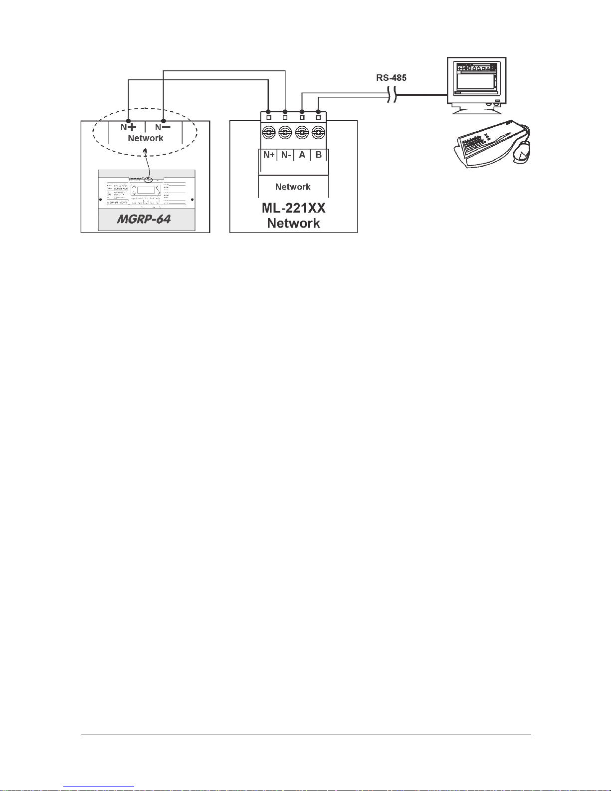
13.3 - Network Card (MLY-2212)
Network module provides to makenetwork connection up 32 panels with MGRP-64 Repeater panel. CONN1 jumper should be
mounted on the network card if the panel is located at the end of line or beginning of line. Providing panel configuration via PC
program.
13.4 - Memory(Event Log) Card (MLY-2213)
• Memory card provides to save event logs for ML-221XX series panels..
• Up to 1000 event log memory.
• It provides to monitor log events in the PC program.
• Providing panel configuration via PC program.
13.5 - Network and Memory (Event Log) Card (MLY-2214)
• Network module provides to makenetwork connection up 32 panels with MGRP-64 Repeater panel. CONN1 jumper should be
mounted on the network card if the panel is located at the end of line or beginning of line. Providing panel configuration via PC
program.
• Memory card provides to save event logs for ML-221XX series panels..
• Up to 1000 event log memory.
• It provides to monitor log events in the PC program.
• Providing panel configuration via PC program.
8 way Sounder card (MLY-2211) Wiring Diagram
Page 10/16KK-642.042 Rev.No:0 01.11.12 ML-221XX User Manual
Network Card (MLY-2212),
Mermory Card (MLY-2213),
Network and Memory Card (MLY-2214) Wiring Diagram

Page 11/16KK-642.042 Rev.No:0 01.11.12 ML-221XX User Manual
Annex-A: Panel Wiring Diagram
Page 12/16KK-642.042 Rev.No:0 01.11.12 ML-221XX User Manual
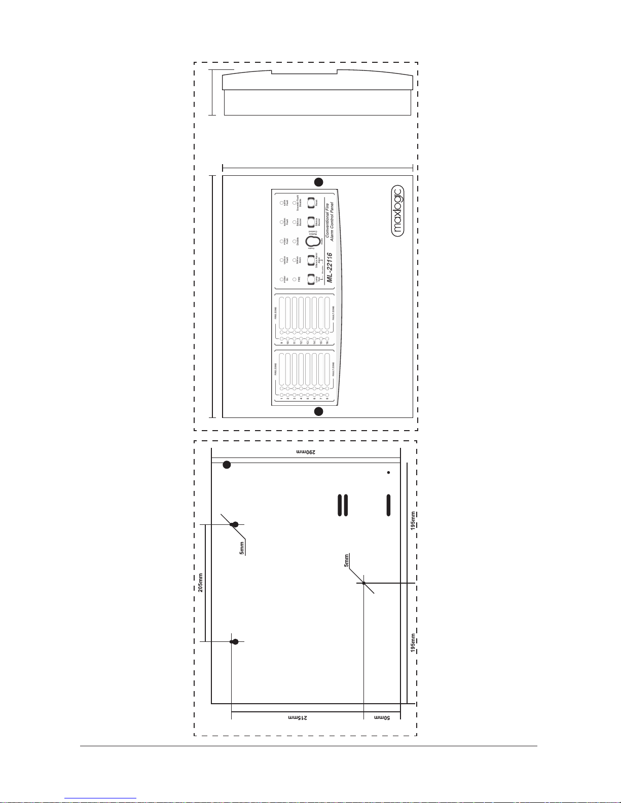
Annex -B: Panel Dimensions
400mm
300mm
100mm

Page 13/16KK-642.042 Rev.No:0 01.11.12 ML-221XX User Manual
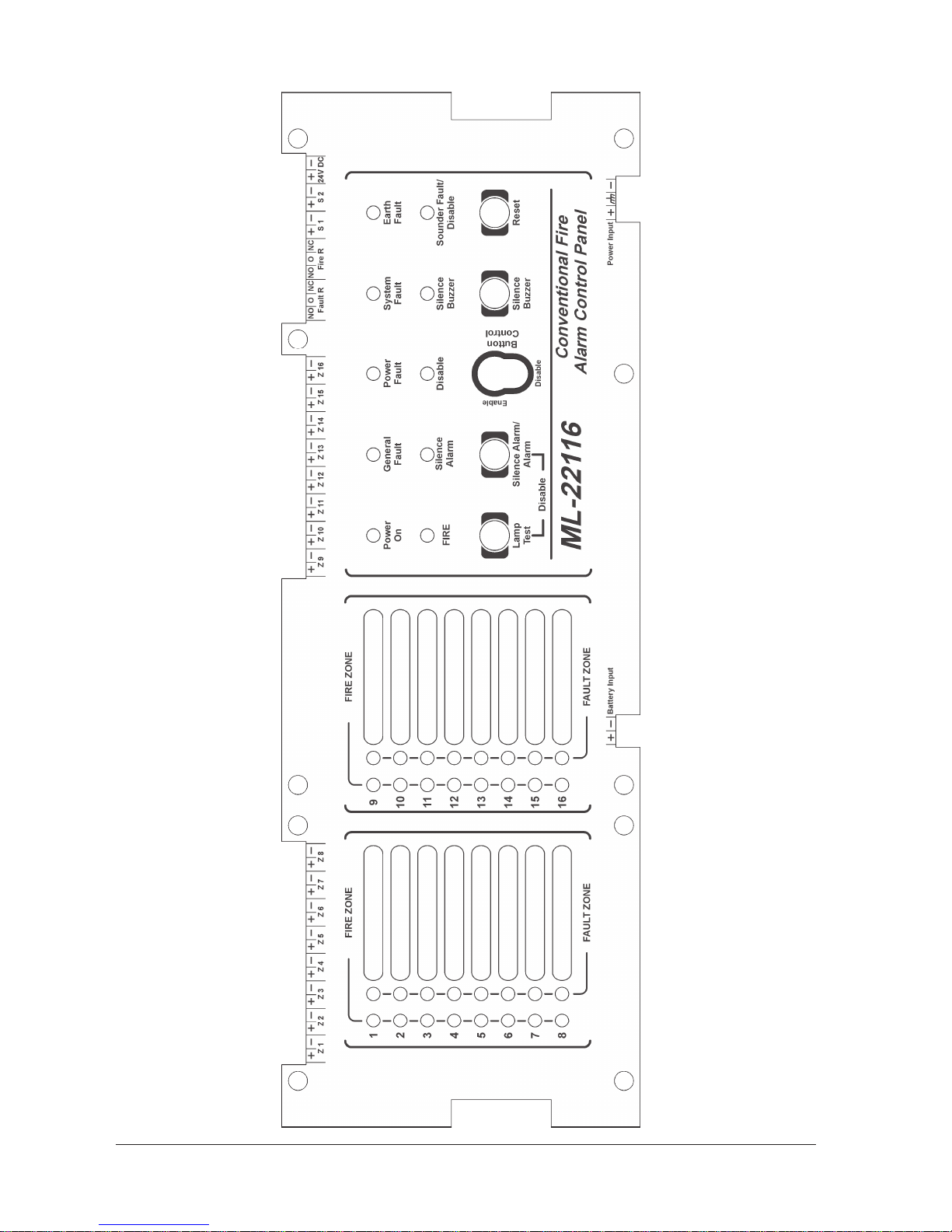
Annex -C1: Panel Serigraphy

Page 14/16KK-642.042 Rev.No:0 01.11.12 ML-221XX User Manual
Annex -C2: Panel Serigraphy

Page 15/16KK-642.042 Rev.No:0 01.11.12 ML-221XX User Manual
Annex -C3: Panel Serigraphy
Page 16/16KK-642.042 Rev.No:0 01.11.12 ML-221XX User Manual
Annex -C4: Panel Serigraphy
 Loading...