

COMMISSIONING, OPERATING AND MAINTENANCE MANUAL
MODEL: MAXLOGIC SERIES
SUB MODEL: INTELLIGENT ANALOGUE ADDRESSABLE
FIRE ALARM CONTROL PANEL
ML-121X

KK-641.002 Rev.No:1 01.08.12 ML-121X User Manual Page | 2
CONTENTS
1- INTRODUCTION .................................................................................................................................... 3
2- WARNINGS ........................................................................................................................................... 4
3- MOUNTING........................................................................................................................................... 4
4- PANEL INPUTS....................................................................................................................................... 5
4.1 Mains power supply ........................................................................................................................ 5
4.2 Batteries ......................................................................................................................................... 5
4.3 Detection Devices Inputs (Loop Lines) ............................................................................................. 5
4.4 Panel PC Connection ....................................................................................................................... 6
5- PANEL OUTPUTS ................................................................................................................................... 6
5.1 Sounder Outputs (4 Units) ............................................................................................................... 6
5.2 Auxiliary Power Supply Output (24 V DC) ......................................................................................... 7
5.3 Relay Outputs (3 Units) .................................................................................................................... 7
6- PANEL BUTTONS AND INDICATORS ....................................................................................................... 8
6.1 Control Buttons ............................................................................................................................... 8
6.2 Front Panel Indicators ................................................................................................................... 10
6.3 Internal Indicators ......................................................................................................................... 11
7- PANEL FUSES ...................................................................................................................................... 11
8- POWERING THE PANEL ....................................................................................................................... 12
8.1. First Boot of Panel ........................................................................................................................ 12
8.2. Booting Previously Configured Panel ............................................................................................. 16
9- FIRE EVENT MESSAGE FORMAT on PANEL LCD SCREEN ....................................................................... 17
10- FAULT EVENT MESSAGE FORMAT ON LCD SCREEN ............................................................................ 18
11- PANEL MENU .................................................................................................................................... 18
12- NETWORKING PRINCIPLES................................................................................................................. 23
13- TECHNICAL SPECIFICATIONS.............................................................................................................. 26
14- PANEL MODELS ................................................................................................................................. 27
ANNEX-A PANEL DIMENSIONS AND MOUNTING HOLES .......................................................................... 28
ANNEX-B CONNECTION SCHEME ............................................................................................................. 29
ANNEX-C PANEL SPARE PARTS ................................................................................................................ 30
ANNEX-D SERIAL COMMUNICATION CABLE ............................................................................................. 31
ANNEX-E SCHEME OF MENU FUNCTIONS ................................................................................................ 32
ANNEX-F NETWORK CONNECTION SCHEME ............................................................................................ 36

KK-641.002 Rev.No:1 01.08.12 ML-121X User Manual Page | 3
Maxlogic ML-121X Series
Intelligent Analogue Addressable Fire Alarm Control Panels
1- INTRODUCTION
Maxlogic ML-121X series intelligent analogue addressable fire alarm control panels are
provided with 0, 1, 2 loop options and 1000 user-defined zone capacity. Up to 127 analogue
addressable devices per loop are allowed to be connected.
Devices operating with VIP protocol such as Photo-Electric Smoke Detectors, Heat Detectors,
Multi-Sensor Detectors, Switch Monitor Modules, Relay Controller Modules, Sounder
Controller Modules, Loop-powered Addressable Sounders and Zone Monitor Modules are
compatible with ML-121X series control panels.
The project planning must be made carefully, in order not to have any difficulties when
commissioning the system. Zone location text (up to 40 characters including blank spaces) for
each device should be predetermined. Then, the devices should be categorized in zones
depending on the physical specifications of the building. After these steps, the panel can be
configured via the software program called ‘Loop Manager’.
The panel is equipped with 4 programmable and fault monitored 24 V DC 500mA sounder
outputs. Panel also contains 3 volt-free 30 V DC 1A relay outputs (fire relay, alarm relay, fault
relay) and a 24V DC 500mA auxiliary power supply output. Furthermore, 4 remote control
inputs (alarm, silence/sound alarm, reset and fault) exist in the panel.
ML-121X series fire alarm control panels have the optional functions described in TS EN 54-2
standards;
Sounder outputs
ML-121X series fire alarm control panels have also the supporting functions described in TS
EN 54-2 standards;
Network: The supporting function used to communicate in network.
NOTE: This user manual is valid for the panel models indicated in 14
th
section.
Producer-manufacturer or importer firms’ title, address, and telephone number
Manufacturer Firm:
MAVILI ELEKTRONIK TICARET VE SANAYI A.S.
SERIFALI MAHALLESI, KUTUP SOKAK NO: 27/1-2-4 UMRANIYE / ISTANBUL / TURKEY
TEL: +90 216 466 45 05 - +90 216 466 45 10
Service stations’ communication information that related spare parts have been
provided
Authorized Services:
MAVILI ELEKTRONIK TICARET VE SANAYI A.S.
SERIFALI MAHALLESI, KUTUP SOKAK NO: 27/1-2-4 UMRANIYE / ISTANBUL / TURKEY
TEL: +90 216 466 45 05 - +90 216 466 45 10
TEKSIS TEKNIK ELEKTRONIK SIS.TIC. VE SAN. LTD. STI.
SERIFALI MAHALLESI, KUTUP SOKAK NO: 27/3 UMRANIYE / ISTANBUL / TURKEY
TEL: +90 216 313 60 60 - +90 216 313 47 49
Expected operation life which has been determined and announced by related ministry
This device’s expected operation life is 7 years.

KK-641.002 Rev.No:1 01.08.12 ML-121X User Manual Page | 4
2- WARNINGS
The panel contains static-sensitive high quality electronic control equipment. Do not use the
panel before reading this manual.
In case of any fault, only the technicians of the manufacturer or technicians authorized by the
manufacturer should repair or maintain the panel.
The person who will operate the system should be well trained on powering and operating the
system.
Two years of warranty is valid from the production date as long as the system is used with
regard of obeying the rules, instructions and recommendations provided by the manufacturer.
Use the recommended cable types defined in this manual for cabling of panel power supply,
sounder power supply and detector line. Do not remove any connections and do not make any
connections while mains power supply is connected. Panel’s earth connection must be made
definitely.
Do NEVER apply 230V AC 50Hz mains power into the detectors and manual call points input
terminals, sounder line outputs and battery connection inputs.
This panel has been designed to operate on 230 V AC 50 Hz power supply. The protective
earth connection must be made definitely and the mains power supply must be presented
through the device via a fuse assigned only to this device. If the earth connection is not made
appropriately, all the conductive parts in the device may result in electrical leakage and this
may create hazard.
‘Automatic Learning’ causes erasing of existing configuration data at the panel. Therefore, it is
recommended to download the configuration data to PC, before ‘Automatic Learning’.
3- MOUNTING
The chosen mounting site of the panel must be clean, dry, not subject to shock or vibration
and easily accessible. The temperature must be in between the temperature range of
-5C° and +50C°. The relative humidity must not be m ore than 95%.
The panel should be mounted on a flat surface in such a way that, the indicators should be at
the eye-level and must not be mounted near the sources of excessive heat or cold and inside
of any cabinet.
Uncover the panel via the allen key provided with the panel.
Panel cable entries from back and top of the panel are available for easy mounting. Mark the
position of the fixing holes according to the respective Annex-A, Figure-2; ensuring that the
wall is flat at the chosen location.
Screws or bolts of a minimum of 4mm diameter must be used to mount the cabinet in all four
mounting positions. Drill and plug the wall then fix the cabinet using all fixing points.

KK-641.002 Rev.No:1 01.08.12 ML-121X User Manual Page | 5
4- PANEL INPUTS
4.1 Mains power supply
The system is designed to operate with 230V AC 50Hz. Earth connections must be made to
earth terminal and earth resistor must be less than 10Ω. The mains supply of the panel must
be via an independent self-resetting fuse rated 230V AC 6A. This fuse must be separate from
the other fuses and a caution note should be written such as ‘ATTENTION! FIRE ALARM
CONTROL PANEL’S FUSE. DO NOT REMOVE’ to ensure safe operation of the panel.
Recommended cable types are 3x2,5 NYM or 3x2,5 NYA. Connections must be done
according to Annex- B, Figure-1.
Do not connect or disconnect loops, mains supply input and PCB connections while the panel
is energized, to avoid an electric shock.
4.2 Batteries
Batteries provide continuity of operation during a failure of the mains power supply. The panel
uses 2 units of 12 V DC 7Ah dry type batteries. Battery connection scheme can be seen from
Annex-B, Figure-14.
4.3 Detection Devices Inputs (Loop Lines)
ML-121X series panels are produced with 0, 1, 2 loop models. Panels with
0 loops (no-loop) are used as repeater panels. Each loop is capable of hosting up to 127
addressable devices. Connection of loop line to the control panel must be as like in Annex-B,
Figure-7. A 0Ω resistor must be connected to the unused loops. Each device in the loop must
be addressed via MG-8200 Address Programmer depending on the architectural project of the
site.
The semi-duplex two-wire digital serial synchronous communication between the devices
connected to the loop and the fire alarm control panel is established by the VIP
communication protocol.
Short circuit isolators must be placed in such a way that more than 20 detectors and/or
manual call points shall not be out of service in case of any short circuit occurrence in the
loop.
The devices should be connected to a one-pair cable to create a loop and should turn back to
the panel from the last device.
The loop is energized from the ‘out’ terminal of the panel and the turn back point toward the
panel is the ‘in’ terminal. In case of rupture or short circuit, the loop is energized from both the
‘in’ terminal and the ‘out’ terminal. Thanks to this functionality; it is provided that the devices,
except from the detectors / buttons which are in failure, go on functioning properly while the
part in failure is isolated.
It should be used the short circuit isolator for each ‘in’ and ‘out’ terminals. Thus, if any problem
occurs in between the part from any of the ‘in’ or ‘out’ terminals to the first short circuit isolator
location, this part is isolated and the rest of the loop can go on functioning properly.

KK-641.002 Rev.No:1 01.08.12 ML-121X User Manual Page | 6
1x2x1,5+0,8J-Y(st)Y, 1x2x0,8+0,8J-Y(st)Y or 1x2x1,5+0,8J-H(st)H, 1x2x0,8+0,8J-H(st)H
coded cables should be used. While cabling (starting from Loop + terminal), cable’s earth line
must be connected to appropriate earth terminal in the control panel (See Annex-B, Figure-2).
This earth line should be installed throughout all detectors and call points. Earthing cables
should be wired after placing detectors and/or call points and line should be ended. When a
return is performed to (Loop -), earthing line should be done as it is shown in Annex-B,
Figure-2 and line is ended.
4.4 Panel PC Connection
4.4.1 PC Port
Cable connection between panel and PC for data communication is plugged into the PC
Socket which found on front panel of (See Annex-B, Figure-11). The communication cable
shown in Annex-D must be used for communication with computer.
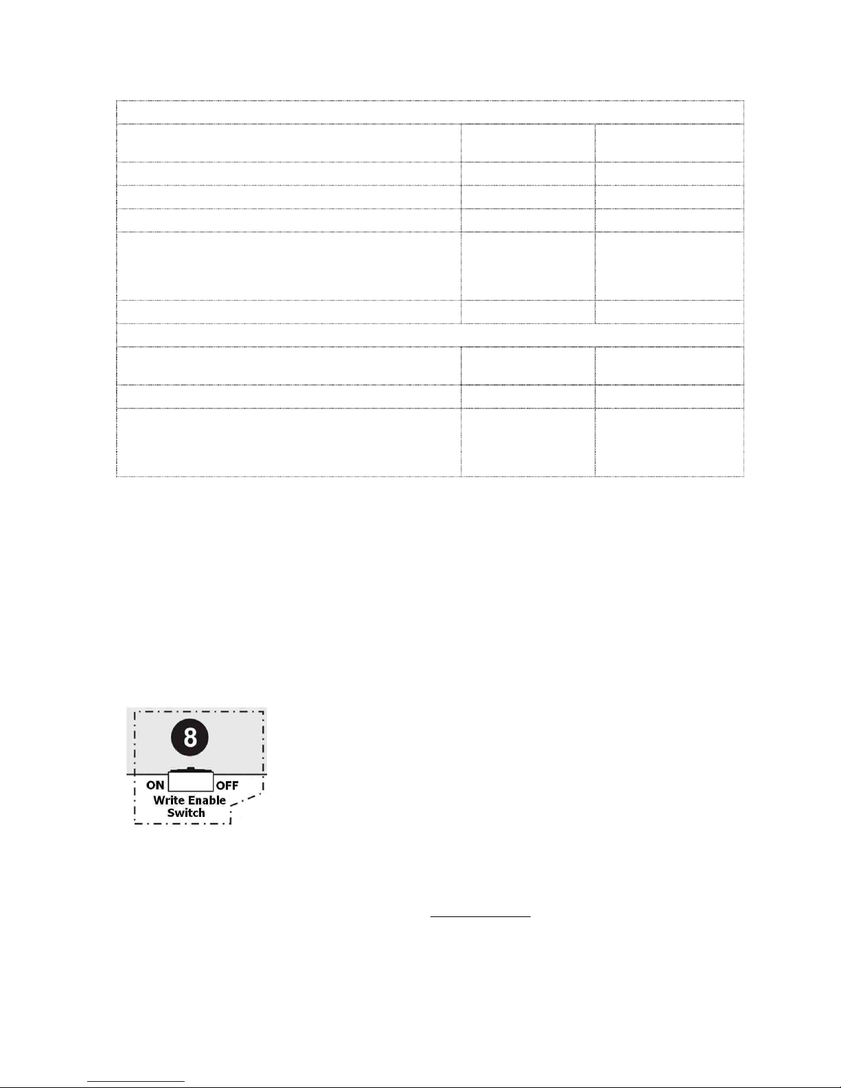
4.4.2 Write Enable Switch
Write enable switch has two positions as “ON” and “OFF”. (Annex-B, Figure-8) When the
panel is energized while the switch is OFF, the panel runs previously saved data. When the
panel is energized while the switch is ON, panel operation modes appears on the screen.
More details are provided in Section-8.
4.5 Remote Control Inputs
There are remote control inputs on the panel which are likely to control the panel remotely by
the help of any remote button. One terminal of the button is connected to the desired input
and other one is connected to GND. (See Annex-B, Figure-6). It should be used the cable with
this code; 2x1,5 N2XH or 2x1,5 NYY for remote control input line.
AL : Reactivates alarm condition, sounders and relays which was silenced and positioned
by Silence Alarm.
FLT : Activates fault condition.
RS : Resets the panel.
SIL : Silences sounders and returns the relays to their initial position.
5- PANEL OUTPUTS
5.1 Sounder Outputs (4 Units)
The panel has 4 sounder outputs rated 24 V DC 500mA. In order to monitor the line against to
open or short circuit conditions, normally 16 V DC reverse voltage is seen from the sounder
outputs. During fire alarm outputs are driven by 24 V DC (Annex-B, Figure-4). Current driven
more than 0.5A leads the panel into the fault condition.
2x1,5 N2XH or 2x1,5 NYY cable should be used for the sounder line. 10KOhm resistor,
located on sounder outputs from factory default is used as end-of-line resistor and must be
connected to the end of the sounder line. Otherwise, open circuit fault is monitored on the
sounder line of panel. In case of any open circuit or short circuit faults occurred, it can be
displayed on the screen of panel with the line number.

KK-641.002 Rev.No:1 01.08.12 ML-121X User Manual Page | 7
5.2 Auxiliary Power Supply Output (24 V DC)
The panel is equipped with an auxiliary 0.5А 24 V DC power supply output. Exceeding this
level causes fault condition. It can be used for supplying power to peripheral devices.
2x1,5 N2XH or 2x1,5 NYY cables should be used for external power supply line. In case of
mains power supply failure, the batteries provide power supply to the output (24 V DC).
(Annex-B, Figure-3).
5.3 Relay Outputs (3 Units)
The panel has 3 units of relay outputs with volt free changeover contacts rated 1A 30 V DC.
These volt-free outputs; fire relay (normally non-energized), alarm relay (normally nonenergized) and fault (normally energized). (Annex-B, Figure-5). 2x1,5 N2XH or 2x1,5 NYY
cable should be used for relay output line.
5.3.1 Fire Relay : The output is activated on any fire event and it can be used to trigger
any other system. The output is returned to its initial position only by pressing ‘Reset’ button
on panel.
5.3.2 Alarm Relay : The output is activated on any fire event and it can be used to activate
any other system. The output is returned to its initial position only by pressing ‘Alarm Silence’
button on panel. If a new alarm occurs, Alarm relay reactivates.
5.3.3 Fault Relay : The output is activated on any fault event, changes its contact in case
of mains failure. The output returns to its initial position, if fault condition is removed and the
‘Reset’ button on the panel is pressed.
Important notice : Fire alarm panel relays operate as signal-based relays. If these relays
will activate any other devices as like control relays, then a contactor should be used between
the relay and device. In case of high current driven applications, the relay outputs can get
damage if there is no contactor. This situation is not subjected to the warranty condition.
KK-641.002 Rev.No:1 01.08.12 ML-121X User Manual Page | 8
6- PANEL BUTTONS AND INDICATORS
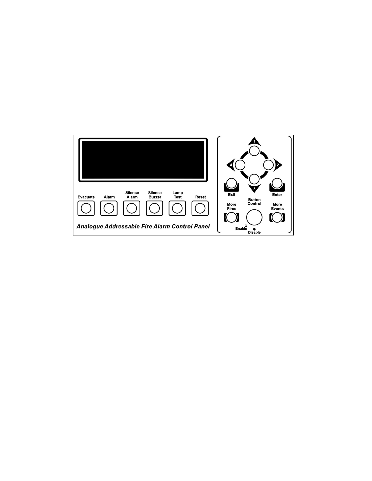
6.1 Control Buttons
While control panel is in normal operating condition, it is in ‘Access Level 1’. In Access Level
1, the buttons; Silence Buzzer, Lamp Test, More Fires, More Events can be used.
The Silence Buzzer, Lamp Test, More Fires, More Events Buttons can be used in Access
Level 1.
Passing ‘Access Level 2’ enables to use other buttons. In order to pass ‘Access Level 2’
button control key is brought to enable position. To prevent unauthorized access, button
control key must always be kept as disable position while panel operating in normal condition.
Evacuate : Used for the purpose of evacuation. It requires to be programmed by
the Loop Manager Program.
Pressing this button:
- Buzzer sounds.
- Sounders ring.
- Alarm and fire relays get activated.
- Fire LEDs and Evacuation LEDs illuminate.
Alarm : Pressing Alarm button reactivates the sounders and relay outputs
which were silenced before.
Silence Alarm : This button is used to silence an alarm and bring relay outputs to their
old positions.
Silence Buzzer : This button is used to silence the internal buzzer which rings during fire
alarm or any fault condition occur in the system.
Lamp Test : It is used to check all the LEDs and LCD screen of the panel whether
they are operate normally or not.
Reset : Resets all existing fire and fault events in the system. Fire and Fault
relays are brought to normal position (if fire and fault condition is not proceeding).

KK-641.002 Rev.No:1 01.08.12 ML-121X User Manual Page | 9
More Fires : Among existing events, if there are more than one fire event, this
button is used to see fire events in the system.
The latest fire event remains at the bottom of the LCD screen. Pressing ‘More Fire’ button
shows all the fire events at the upper part of the LCD screen.
Z o n e s I n A l a r m : 1 A l a r m : 2 F a u l t : 1
* F I R E : M G 6 2 0 8 8 - W a y S w . M o n . Z o n e : 1 *
P : 0 L : 1 A : 2 8 M L - 1 2 X X R e - i n i t i a t e d
_ _ _ _ _ _ _ _ _ _ _ _ _ _ _ _ _ _ _ _ _ _ _ _ _ _ _ _ _ _ _ _ _ _ _ _ _ _ _ _
* F I R E : M G 6 2 0 8 8 - W a y S w . M o n . Z o n e : 1 *
P : 0 L : 1 A : 2 8 M L - 1 2 X X R e - i n i t i a t e d
More Events : If more than one event occurs, it is possible to see all other events by
pressing this button. Pressing this button categorizes the events. It is possible to check other
events by pressing ‘1(UP)’, ‘3(DOWN)’ buttons. To see the desired event category, press the
button with number ‘2 (RIGHT)’. To get back to the main category press ‘EXIT’ button.
Event categories as below ;
Fires
Tech. Alarms
Announce Event
Informations
Evacuates
Tech. Faults
FF Tel. Event
Disablements
Faults
Alerts
Analog Event
Test
Pre-Alarms
Securities
Internal Events
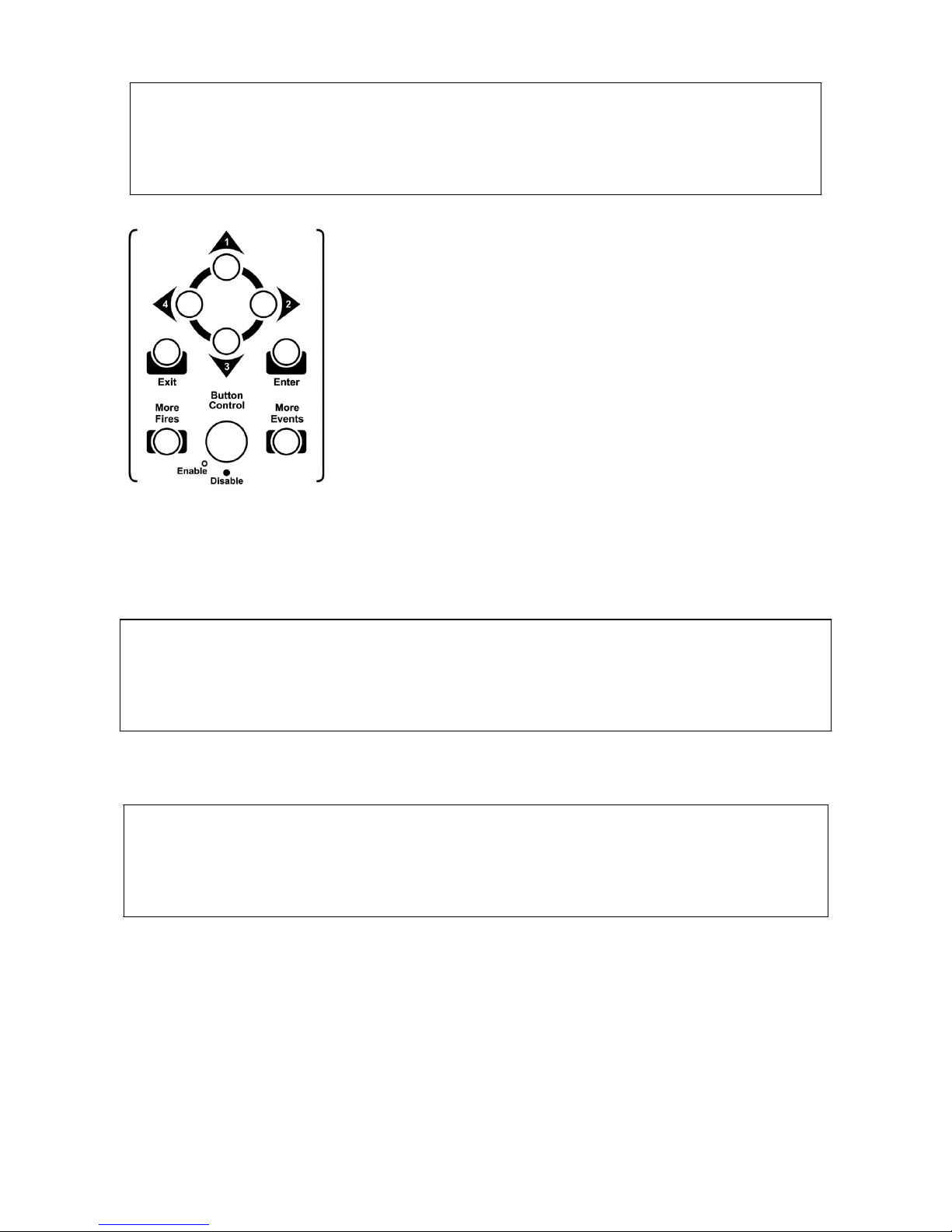
Direction buttons:
Button number ‘1’ : It is used to go upward in the panel’s main menu screen and in the
‘More Events’ menu.
Button number ‘2’ : It is used to select the desired feature in panel’s main menu and
desired category in ‘More Events’ screen and go to right direction.
Button number ‘3’ : It is used to go downward in the panel’s main menu screen and More
Events menu.
Button number ‘4’ : It is used to go back to previous menu and go to left direction.
Enter : Enter Button is used to see the menu screen and select the desired
feature inside the menu.
Exit : It is used to go back to previous menu when LCD screen shows main
panel menu or go back to categories menu from the selected category.
Note: Menu features are described in detail in the 11
th
section of Panel menu. To see the
transitions among menu features please check ANNEX-E Scheme of Menu Functions.
W/Dog Reset : Used for elimination error in case of ‘System Fault’ LED illuminates.
However, if the LED illuminates because of any fault in the central microprocessor preventing
the program to run; the button will be useless for this situation (ANNEX-B, Figure-9).
Microprocessor Reset: Microprocessor can be reset by pressing the ‘Microprocessor Reset’
button. (ANNEX-B, Figure-13)
LCD Lighting : Used to adjust the LCD display contrast with the aid of trimpot
(ANNEX-B, Figure-10).
KK-641.002 Rev.No:1 01.08.12 ML-121X User Manual Page | 10
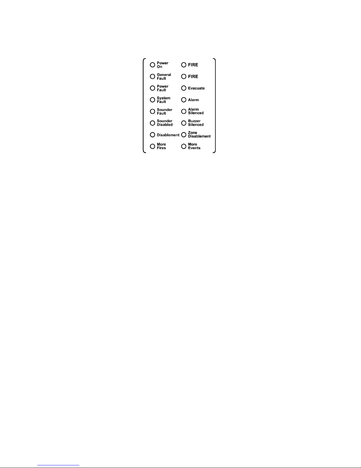
6.2 Front Panel Indicators
FIRE : Fire LEDs illuminate in two conditions; if there is a fire situation in the
system or in case of pressing Evacuate button. Each one of these conditions makes the LEDs
illuminate in ‘Red’ colour.
Power On : Panel is energized and operates normally. It illuminates as ‘Green’
continuously.
General Fault : If any fault occurs during operation. It illuminates with the specified
respective faults such as power fault. It illuminates as ‘Yellow’.
Power Fault : It indicates that there is a mains power failure or a problem of battery.
It illuminates as ‘yellow’ and related fault condition can be viewed on the LCD screen.
System Fault : Main microprocessor fault. It Illuminates as ‘Yellow’.
Sounder Disabled : It shows that the sounder outputs on the panel has been disabled and
illuminates as ‘yellow’.
Disablement : If any device or line disabled in the system this LED illuminates as
‘Yellow’.
More Fires : It indicates the presence of more than one fire in the existing event list
of the system. It illuminates as ‘Yellow’.
Evacuate : It indicates that the Evacuate button is pressed. The Evacuate button
must be programmed by Loop Manager Software Program. It illuminates as ‘Red’.
Alarm : It indicates that the alarm button is pressed, it illuminates as ‘Yellow’.
Alarm Silenced : This led shows that incoming alarms are silenced by pressing ‘Alarm
Silenced’ button. It illuminates as ‘Yellow’.
Buzzer Silenced : It indicates that the Buzzer Silenced button is pressed and it
illuminates as ‘Yellow’.
Zone Disablement : It indicates that one or more zones are disabled from the panel menu.
It illuminates as ‘Yellow’.
More Events : If there is more than one event in the system this LED illuminates as
‘Yellow’.

KK-641.002 Rev.No:1 01.08.12 ML-121X User Manual Page | 11
6.3 Internal Indicators
Internal Indicators on SLCU (Single Loop Card Unit) (Annex-B, Figure-16);
SEND LED: While sending communication signal to the devices in the loop, it blinks as RED.
RECEIVE LED: While receiving responses from the devices in the loop, it blinks as
GREEN.
7- PANEL FUSES
Fuses on the panel;
SLCU Fuse (FS1) is a self-resetting fuse and becomes active on 0.5А current overload at the
loop output line. The General fault LED illuminates and on LCD screen ‘Loop open or Short
circuit’ comment is seen. Panel’s loop output becomes unusable. In each single loop card this
fuse is present.
Sounder 1 Self-resetting fuse (FSO3)
Self-resetting and becomes active on 0.5А current overload. Sounder fault Led illuminates,
and on LCD screen ‘Sounder 1 open circuit’ message is seen. Panel’s sounder-1 output
becomes unusable.
Sounder 2 Self-resetting fuse (FSO4)
Self-resetting and becomes active on 0.5А current overload. Sounder fault Led illuminates,
and on LCD screen ‘Sounder 2 open circuit’ message is seen. Panel’s sounder-2 output
becomes unusable.
Sounder 3 Self-resetting fuse (FSO5)
Self-resetting and become active on 0.5А current overload. Sounder fault Led illuminates, and
on LCD screen ‘Sounder 3 open circuit’ message is seen. Panel’s sounder-3 output becomes
unusable.
Sounder 4 Self-resetting fuse (FSO1)
Self-resetting and becomes active on 0.5А current overload. Sounder fault Led illuminates,
and on LCD screen ‘Sounder 4 open circuit’ message is seen. Panel’s sounder-4 output
becomes unusable.
24 V DC Self-resetting Fuse (FSO2)
Self-resetting and becomes active on 0.5А current overload or wrong connection into the
output. The General fault LED illuminates and ‘24 V Fault’ comment is seen on LCD screen.
24 V DC output becomes unusable.
Internal Indicators on MLY-0502 Power Supply;
28 V input fuse (F1)
3 A self-resetting fuse becomes active in case the power supply becomes faulty.
Battery fuse (F2)
1.1 A self-resetting fuse becomes active upon any fault or short circuit at battery inputs.
28 V output fuse (F3)
3A self-resetting fuse becomes active upon short circuit in 28 V output of power supply. In this
case, the outputs of power supply become de-energized.
Note: the placement of the fuses is shown in Annex-B.
KK-641.002 Rev.No:1 01.08.12 ML-121X User Manual Page | 12
8- POWERING THE PANEL
8.1. First boot of panel
Operation Panel Status Write Enable Switch
Position
8.1.1. Cabling OFF (Not-energized) OFF (OFF Position)
8.1.2. Checking cabling OFF (Not-energized) OFF (OFF Position)
8.1.3. Addressing OFF (Not-energized) OFF (OFF Position)
8.1.4. Determining connected
devices
8.1.4.1. Re-Initiate System (Automatic Learning)
8.1.4.2. PC Program
ON (Energized) ON (ON Position)
8.1.5. Booting panel ON (Energized) OFF (OFF Position)
8.2. Booting Previously Configured Panel
Operation Panel Status Write Enable Switch
Position
8.2.1. Using updated data ON (Energized) OFF (OFF Position)
8.2.2. Reconfiguring the panel
8.2.2.1. Updating Panel Configuration File
8.2.2.2. Using Valid Data
ON (Energized) ON (ON Position)
8.1. First Boot of Panel
8.1.1. Cabling: Before powering the panel, all connections should be made properly
depending on the connection scheme in ANNEX-B.
8.1.2. Checking cabling: All the connected cables (sounder line, loop etc.) should be
checked for short circuit, open circuit (broken line) etc.
8.1.3. Addressing: All devices in the loop should be assigned to a unique address number
by ‘MG-8200 Address programmer’ device, with regard of architectural project of the site.
8.1.4. Determining connected devices: The devices connected to the panel loop lines
must be determined properly.
In order to determine connected devices, the panel is energized while
‘Write Enable Switch’ is ‘ON’.
(Annex-B, Figure-8)
The below screen appears. The operation shall be selected.
Re-Initiate System (Automatic Learning)
PC Program
Use Valid Data (In case the panel is energized for the first time, panel memory is empty and
this option cannot be selected at the first system boot.)
KK-641.002 Rev.No:1 01.08.12 ML-121X User Manual Page | 13
S e l e c t C o n f i g T y p e
R e - I n i t i a t e S y s t e m
P C P r o g r a m
U s e V a l i d D a t a
_ _ _ _ _ _ _ _ _ _ _ _ _ _ _ _ _ _ _ _ _ _ _ _ _ _ _ _ _ _ _ _ _ _ _ _ _ _ _ _
[ U p / D o w n ] : S c r o l l i n g [ E n t e r ] : A c c e p t
From the screen above, the configuration type is selected.
It is possible to scroll up and down in the menu by using ‘1’
and ‘3’ buttons, to confirm the selection press ‘Enter’ button.
8.1.4.1. Re-Initiate System (Automatic Learning)
Automatic learning is the operation that the panel scans and saves all devices connected to
the loop lines one by one.
Auto learning is activated by pressing ‘ENTER’ button. Below screen is displayed:
S e l e c t C o n f i g T y p e
C l e a r V a l i d D a t a ?
_ _ _ _ _ _ _ _ _ _ _ _ _ _ _ _ _ _ _ _ _ _ _ _ _ _ _ _ _ _ _ _ _ _ _ _ _ _ _ _
[ E x i t ] : C a n c e l [ E n t e r ] : A c c e p t
Activating this option will erase the panel memory and re-configure the system by scanning all
devices.
S e l e c t C o n f i g T y p e
D i s a b l e P r o g r a m E n a b l e S w i t c h
_ _ _ _ _ _ _ _ _ _ _ _ _ _ _ _ _ _ _ _ _ _ _ _ _ _ _ _ _ _ _ _ _ _ _ _ _ _ _ _
[ E x i t ] : M a i n M e n u
When program enable switch is OFF, Automatic Learning starts. As a result, new
configuration data is created depending on the currently connected devices and the previous
configuration data is erased. The new data is saved to the memory of panel.
8.1.4.2. PC Program
A special software program called ‘Loop Manager’ is used for programming the panel.
Creating zone location texts, creating cause-effect scenarios, device settings etc. are all done
through ‘Loop Manager’ Software.

KK-641.002 Rev.No:1 01.08.12 ML-121X User Manual Page | 14
The communication between panel and computer is established while the panel is in normal
operating mode or while ‘Write Enable Switch’ is ‘ON’.
The serial communication cable is connected to the PC socket which found on the panel front
cover. (For the cable connection, see Annex-D)
The selection of ‘Download from Panel’ or ‘Upload to Panel’ operations is made through the
‘Loop Manager’ Software as shown on the below screen.
Data transfer can be initiated through the Loop Manager; there is no need to follow any
procedure on the panel. It is sufficient to click on ‘Start Downloading’ Button.
When data transfer completed, the following comment is displayed on the program;

KK-641.002 Rev.No:1 01.08.12 ML-121X User Manual Page | 15
In case any communication fault occurs, the below screen appears:
In this case, the panel should be deenergized, the connection cables should be checked and
all the above steps should be repeated after debugging the problem.
8.1.5. Booting panel:
At the end of automatic learning or computer/panel communication, system boots in normal
operation mode.
On the LCD screen of the panel following comment is seen;

KK-641.002 Rev.No:1 01.08.12 ML-121X User Manual Page | 16
L I N E I
N
I
T
I A T I N
G
P l e a s e W
a
i t .
After uploading or downloading, panel gets back to its normal condition as below;
M a v i l i E l
e k t r o n
i k A . S . 0
2 1 6 4 6 6 4 5 0 5
V e r s i o
n : 1 . 0 .
2 2
M L - 1 2 X X R e - i n i t i a t e d
A c c e s s L e v e l 2
_ _ _ _ _ _ _ _ _ _ _ _ _ _ _ _ _ _ _ _ _ _ _ _ _ _ _ _ _ _ _ _ _ _ _ _ _ _ _ _
[ E n t e
r
] : M e n u
8.2. Booting Previously Configured Panel
8.2.1. Using updated data:
If the panel is turned OFF for some reasons, the rebooting should be while ‘Write Enable
Switch’ is ON in order to start with actual data.
Upon energizing the panel, the internal units are checked and results are reported.
The internal units which are checked during the system start-up:
Supervisor
Port (1)
XNCU
SLCU (loop)
Panel Status
General Leds Driver
TCP/IP
Pcus
LCD
Power Unit
Zone Leds (1..32)
Printer
Port (0)
I/O Driver
Zone Leds (33..64)
Network
Status information format of checked units in the panel is as like OK/Fault. In case the internal
device has version number, then this number appears on the screen.
Panel automatically starts to load the information after 10 seconds countdown and go over to
normal operating condition. During 10 seconds countdown, report results of the internal units
can be seen by using ‘1’ and ‘3’ buttons or ‘write enable switch’ position can be changed.
After panel displays all detected units on to screen, the data is loaded automatically and panel
pass to normal operating mode.
M a v i l i E l
e k t r o n
i k A . S . 0
2 1 6 4 6 6 4 5 0 5
V e r s i o
n : 1 . 0 .
2 2
M L - 1 2 X X R e - i n i t i a t e d
A c c e s s L e v e l 2
_ _ _ _ _ _ _ _ _ _ _ _ _ _ _ _ _ _ _ _ _ _ _ _ _ _ _ _ _ _ _ _ _ _ _ _ _ _ _ _
[ E n t e r ] : M e n u
8.2.2. Reconfiguring the panel:
Reconfiguring of an already existing panel may be necessary for some reasons like adding
new device(s), removing device(s), updating zone location text information and changing
device settings etc.

KK-641.002 Rev.No:1 01.08.12 ML-121X User Manual Page | 17
Panel is energized while ‘Write Enable Switch’ is in ‘ON’ position. The screen to select
operating mode appears:
Re-Initiate System (Automatic learning results in erasing the already existing data (such as
zone location texts etc.). For this reason this information must be well noted.)
PC Program (It is also possible to update data in normal operating mode.)
Use Valid Data
8.2.2.1. Updating panel configuration file:
Previously created (if it exists) configuration file (*.hrz) is open through Loop Manager
software or the data is downloaded from the panel. The desired changes are made and finally,
the file is uploaded to panel. (See, Section 8.1.4.2. PC Program)
8.2.2.2. Using valid data:
In order to select ‘Use Valid Data’ option, panel is energized while ‘Write Enable Switch’ is
‘ON’. In this configuration type; the latest data is reloaded to the panel and activated. If there
is no correct data kept in the panel memory, then this option will not be avail able to be
selected. (It is also possible to load automatically the data saved to panel by turning ON the
panel while ‘Write Enable Switch’ is ‘ON’.)
To keep the previous data in panel memory is provided by the battery. If the battery detaches
or broken then all the data kept in the panel get lost.
9- FIRE EVENT MESSAGE FORMAT on PANEL LCD SCREEN
On fire event, the panel displays a message in 4 lines as shown below; alarm relays and fire
relays get activated, buzzer and sounders ring.
Z o n e s I n A l a r m : 1 D i s . : 2 F a u l t : 1
* F I R E : M G 6 2 0 8 8 - W a y S W . M o n . Z o n e : 1 *
P : 0
L
: 1 A : 2 8 M L - 1 2 X X R e - i n i t i a t e d
F L O O R C O R R I D O R
1. In the 1
st
row following information is displayed;
Zone In Alarm: Number of Alarm at the zones
Disablements: Total number of disablements
Fault: Total number of faults
2. In the 2
nd
row; the device model and zone number in which fire alarm comes is
dispalyed.
3. In the 3
rd
row; panel, loop, address number, and panel name of the device in which fire
alarm comes is displayed.
4. In the 4
th
row; zone name of the device where fire alarm comes is displayed.

KK-641.002 Rev.No:1 01.08.12 ML-121X User Manual Page | 18
10- FAULT EVENT MESSAGE FORMAT ON LCD SCREEN
On fault event, the panel displays a message in 6 lines as shown below; fault relays get
activated and buzzer rings.
Z o n e s I n A l a r m : 0 D i s . : 0 F a u l t : 1
* F A U L T - M G 9 4 0 0 M u l t i s e n s o r Z o n e : 1 *
P : 0 L : 1 A : 2 8 M L - 1 2 X X A u t o - l e a r n e d
M E E T I N G R O O M
D i s c o n n e c t e d D e v i c e
1. In the 1
st
row following information is displayed;
Zone In Alarm: Number of Alarm at the zones.
Disablements: Total number of disablements
Fault: Total number of faults
2. 2
nd
row is empty.
3. In the 3
rd
row; the device model and zone information is displayed.
4. In the 4
th
row; location information of the faulty device is displayed. (Panel No., the
faulty device (like SLCU, PCU, NCU), address information if the device is addressable,
panel name)
5. In the 5
th
row; zone location text of the faulty device is displayed.
6. In the 6
th
row; fault type is displayed.
11- PANEL MENU
There are 3 access levels in order to prevent unauthorized access.
a) Access level 1: ‘Button Control’ key is ‘Disabled’. In this case; ‘Silence Buzzer’, ‘Lamp
Test’, ‘More Fires’, ‘More Events’ buttons can be used. ‘Button Control’ key must be switched
ON in order to unlock other buttons.
b) Access level 2: Some menu functions are active in this access level. Press ‘Enter’ while
‘Button Control’ key is enabled to access panel menu.
The button number ‘1’ is used to move ‘up’, and the button number ‘3’ is used to move
downward. To confirm the selected option press ‘enter’ button or press the button number ‘2’.
In order to get back to previous menu, press ‘Exit’ or press the button number ‘4’.
ACCESS LEVEL 2 MENU
+DEVICES
+DISABLEMENTS
+SET SYSTEM TIME
+FIRE ALARM COUNTER
+DELAY CONFIGURATION
+TEST
+ACCESS LEVEL 3
ACCESS LEVEL 2 MENU INSTRUCTIONS
+DEVICES: The following information for the devices connected to every single loop can be
displayed: Address information, zone location texts, device models, analogue values, status of
devices (Enabled/Disabled).

KK-641.002 Rev.No:1 01.08.12 ML-121X User Manual Page | 19
+DISABLEMENTS: It is possible to temporarily disable loop(s), zone(s), device(s), and
sounder(s). This option would typically be necessary during maintenance of the system or
painting, construction workings, etc. on the site, where the fire alarm system is installed, to
avoid faulty alarms.
+Disable Loop: It is possible to disable desired loop(s).
+Disable Zone: It is possible to disable desired zone(s).
+Disable Device: It is possible to disable desired device(s).
+Disable Sounder: By selecting this option, it is possible to disable all sounders
connected to the sounder line outputs, all addressable sounders connected to the loop line
and all sounders connected to the sounder controller module.
+SET SYSTEM TIME: It is possible to make the adjustments of Year, Month, Day, Hour and
Minute. (The correct system time is vital in proper registration of events.)
+FIRE ALARM COUNTER: Total number of fire events, which occur after installation of the
fire alarm system, can be displayed.
+DELAY CONFIGURATION: It is possible to activate or deactivate all delay values which are
assigned to output devices through ‘Loop Manager’ software.
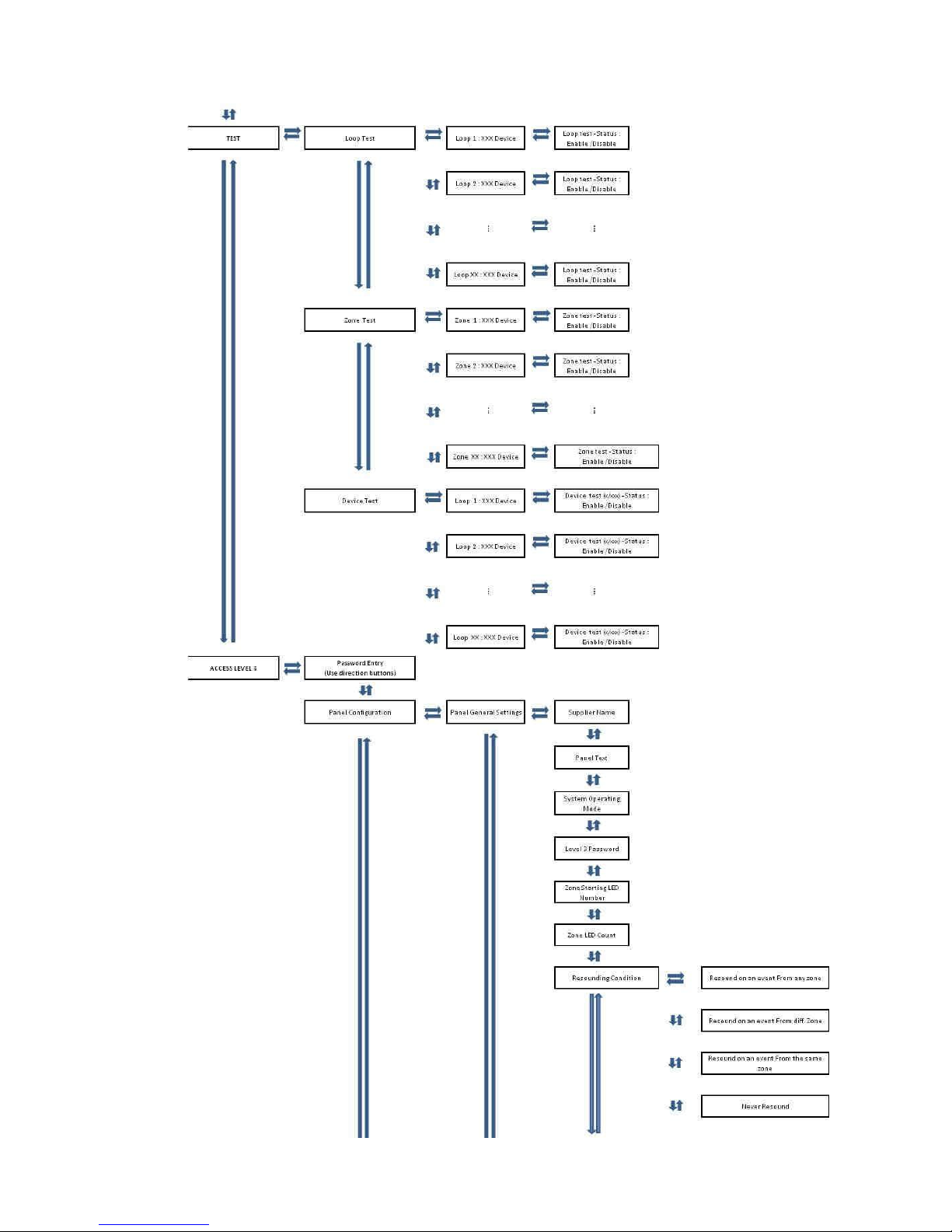
+TEST: It is possible to test the system by activating loop(s), zone(s) and device(s) for a while
(Access level 3 – Test Reset Delay). This allows the system to be tested by only one single
person.
+Loop Test: It is possible to test desired loop(s).
+Zone Test: It is possible to test desired zone(s).
+Device Test: It is possible to test desired device(s).
+ACCESS LEVEL 3:
c) Access level 3:
Special settings can be made from this menu. ‘Access Level 3’ option must be selected to get
access to ‘Access Level 3 Menu’. “1,3,4,2” Password must be entered to Password Entry
field by using direction buttons. (This password can be personalized through Loop Manager
(Panel Settings - > Level 3 Password).)
ACCESS LEVEL 3 MENU
+Password Entry (Use direction buttons)
+Panel Configuration
+Event Logs
-Print Configuration
+Edit Event
+SLCU App. Software
+Contamination Control
-Analog Update
ACCESS LEVEL 3 MENU INSTRUCTIONS
+Password Entry (Use direction buttons):
+Panel Configuration: By selecting this option, special settings can be made
for the panel. The followings are available settings to be made.
-Panel General Settings:
-Supplier Name: The company name (and contact information)
information which will be displayed on panel screen in normal operating mode can be

KK-641.002 Rev.No:1 01.08.12 ML-121X User Manual Page | 20
modified. (The text to be entered should be max. 40 characters length.)
-Panel Text: A special desired name can be assigned to the
panel. (Site name, block na me in which the panel is installed can be chosen as Panel Name.
(The text to be entered should be max. 20 characters length.)
-System Operating Mode: Two different modes exist: “Common
Operating Mode” and “Zonal Operating Mode”.
In case “Common Operating Mode” is selected; all output devices (sounders, relay outputs
etc.) activate upon any fire alarm from any input devices (detectors, manual call points etc.).
In case “Zonal Operating Mode” is selected; upon any fire alarm from any zone, all output
devices (sounders, relay outputs etc.) only in the same zone get active.
-Level 3 Password: Level 3 password is displayed here to
authorize any user to access level 3 menu.
-Zone Starting LED Number: The system devices can be
assigned to a zone (Total amount of Zones is 1000). 64 units of LED exist on the panel front
cover. The first LED number of the interval (64/1000) to be monitored by LEDs is indicated
here.
-Zone LED Count: Total amount of LEDs on panel front cover is
indicated here. (32 or 64 depending on model type)
+Resounding Condition: If the devices, which activated upon a
fire event, are silenced by pressing ‘Silence Alarm’; the reactivation condition of these related
devices is selected here.
-Resound on an event From any zone
-Resound on an event From diff zone
-Resound on an event From the same zone
-Never resound
-Bypassing Condition: Delay value, which is assigned to output
devices (sounders, relays) through ‘Loop Manager’, can be canceled under some conditions.
These conditions are displayed here.
-Bypassing CE delays: Delay value of output devices
(sounders, relays) which are involved in a scenario (which created through ‘Loop Manager’)
can be canceled under some conditions. These conditions are displayed here.
** The Cause Effect (CE) Scenario(s) is created through ‘Loop Manager’ Software. The Cause
Effect Scenario indicates which output devices will be activated upon activation of which input
devices.
-Resounding Scenario Events: Upon activation of any
scenario, the output devices involved in scenario become active. If these output devices
(sounders, relays) are silenced by pressing “Silence Alarm”, the reactivation condition is
displayed here.
-Resetting Scenario Triggered Events: The resetting condition
of the created scenario is displayed here.
-Scenario Activation: The condition, which will affect the
activation of scenario, is displayed here.
-Programming Switch Usage: Write Enable Switch is to be
ON, before erasing event logs. By this way, it is possible to prevent unauthorized pe rsons to
access the panel.
-Global Silence: When selected as active; all outputs can be
silenced by pressing ‘Silence Alarm’ button. When selected as passive; only devices, which
are marked as “Yes” for “Is silenceable Output?” parameter to be accessed through Loop

KK-641.002 Rev.No:1 01.08.12 ML-121X User Manual Page | 21
Manager in “Device Settings” section, can be silenced by pressing ‘Silence Alarm’ button.
+Automatic Reset Delay Configuration:
+Test Reset Delay:
-Test Reset Delay: 6-30 sec.: This indicates the
‘TEST’ duration, which is enabled from Access Level 2 Menu. After the selected value of time,
the output devices get back to its normal statuses without need of any further manipulation.
+Type A Dependency Reset Delay: In case of any fire
alarm from any device in defined zone, the panel goes into ‘PRE-ALARM’ mode. Sounders do
not ring; pre-alarm message is displayed on screen. In case of any other fire alarm from the
same zone within the adjusted time, the panel goes into ‘ALARM’ mode.
-Type A Reset Delay: 30-1800 sec.: In type A
dependency; in case of any fire alarm from the previously defined zone, countdown duration
starts. During this time, a second fire alarm is expected. If a second fire alarm is not received
from the same zone within the adjusted time (30-1800sec.), then the first alarm state is reset
and pre-alarm message on panel screen disappears.
+Type B Dependency Reset Delay: In case of any fire
alarm from any device in defined zone, the panel goes into ‘PRE-ALARM’ Mode. Sounders do
not ring; the pre-alarm message appears on screen. In case of any other fire alarm from any
zone (the same or different zone) within the adjusted time, the panel goes into ‘ALARM’ mode
and sounders ring.
-Type B Reset Delay: 30-1800 sec.: In type B
dependency; in case of any fire alarm from the previously defined zone, countdown duration
starts. During this time, a second fire alarm is expected. If a second fire alarm is not received
from the same or different zone within the adjusted time (30-1800sec.), then the first alarm
state is reset and pre-alarm message on panel screen disappears.
-Panel Time Settings: It is possible to set system time as year, month,
day, hour and minute. (The correct system time is vital in terms of proper registration of
events.)
+Panel Version Information: This feature is used to display the version
information of panel internal cards.
(xMCU, sLCU, xNCU, cPCU)
XMCU: 1.0.XX-0.0.0
SLCU: 1.0.XX-0.0.0
NCU: 1.0.XX-0.0.0
PCU: 1.0.XX-0.0.0
-Network Status: This feature is used to display other panel address
information in the network. (If there is a network)
+Event Logs: All events are saved to the memory of panel. It is possible to
display and print-out all events from due to the installation time of panel.
+View by Category: The event logs are displayed as being categorized
depending on the event types.
Fires: x
Evacuates: x
Faults: x
Pre-Alarms: x
-View by list: All events are sorted.

KK-641.002 Rev.No:1 01.08.12 ML-121X User Manual Page | 22
+Print by Category: The event logs are printed-out as being
categorized depending on the event types.
Fires: x
Evacuates: x
Faults: x
Pre-Alarms: x
+Print by List: All events are printed-out.
-Start to Print
-Clear Event Logs: All event logs are erased.
-Print Configuration: This feature is used to print-out panel settings.
+Edit Event: This feature allows determining for how the panel will give
warning in case of ‘New Device’ and ‘Disconnected Device’ states.
-Disconnected device: (Fault/Warning): The message is displayed in
case the panel cannot communicate with any device. In this case, the panel will give ‘Fault’ or
‘Warning’. It is possible to select the panel behavior upon disconnected device by this feature.
-New device: (Fault/Warning): The message displayed when detecting
a new device, which is not included in the configuration file. In this case, the panel will give
‘Fault’ or ‘Warning’. It is possible to select the panel behavior upon newly added device by this
feature.
+SLCU App. Software: Version update of panel loop cards can be done with
the aid of this feature. Version update can only be done by the manufacturer.
-LCU 1 – B.V. (1.0.0) /A.P.P.V. (1.0.12)
+Contamination Control: The system devices may be contaminated in time
because of the environmental reasons. These devices can cause “FALSE ALARMS”. In order
to prevent this issue, a regular maintenance must be made periodically. Panel is able to
display contamination level of connected devices. Devices contamination levels can be
checked for one loop or for all loops.
+General:
+Automatic Control: In case this option is selected, devices
connected to the system are continuously checked for any contamination. Interrogation count
can be selected as (8, 16, 64, 255). The contamination control is done depending on the
selected value. An analogue value greater than 75 is considered as the contamination
threshold by the panel. Upon detecting any contaminated device, a message appears on the
screen. This message disappears after cleaning or replacing the device with the new one and
resetting the panel.
+Interrogation Count: x
-Measuring contamination status
C o n t a m i n a t i o n C o n t r o
l
M e a s u r i n g c o n t a m i n a t i o n s t a t u s
_ _ _ _ _ _ _ _ _ _ _ _ _ _ _ _ _ _ _ _ _ _ _ _ _ _ _ _ _ _ _ _ _ _ _ _ _ _ _ _
[ E x i t / L e f t ] : B a c k

KK-641.002 Rev.No:1 01.08.12 ML-121X User Manual Page | 23
+Manual Control: When this option is selected, all system
devices are checked instantaneously for contamination. Interrogation count for measuring
contamination status is selected between 8-255. The interrogation count represents the
amount of measurements. An analogue value greater than 75 is considered as the
contamination threshold by the panel. Upon detecting any contaminated device, device(s)
listed. After cleaning devices the contamination control should be repeated.
Loop: n
+Measure
-Interrogation Count: x
-List Results
-Print Results
+Automatic Control
+Interrogation Count: x
-Measuring Contamination Status
+Manual Control
-Measure
-Interrogation Count: x
+List Results
+Print Results
C o n t a m i n a t i o n C o n t r o l
M G 9 1 0 0 O p t
.
S m o k
e D e
t . Z o n
e :
1
P :
1
L : 1 A
: 4 3
C o n t a m i n a t e d d e v i c e
_ _ _ _ _ _ _ _ _ _ _ _ _ _ _ _ _ _ _ _ _ _ _ _ _ _ _ _ _ _ _ _ _ _ _ _ _ _ _ _
[ U p / D o w n ] : S c r o l l [ E n t e r ] : U p d a t e
-Analog Update: Due to this feature, the analogue values of system devices
can periodically be followed.
Note: See, Annex-E Menu Functions Scheme for switch between menu functions.
12- NETWORKING PRINCIPLES
So that Maxlogic series fire alarm control panels can operate in network, each panel must contain 1 unit
of ML-1201 Network Module.
Please, see Section “15- Panel Models” which includes ML-121X.N models having network module by
default. ML-1201 Network Module should NOT be added for those panels which have a network
module by default.
ML-1201 Network Module is compatible with all Maxlogic Series Intelligent Analogue Addressable Fire
Alarm Control Panels.
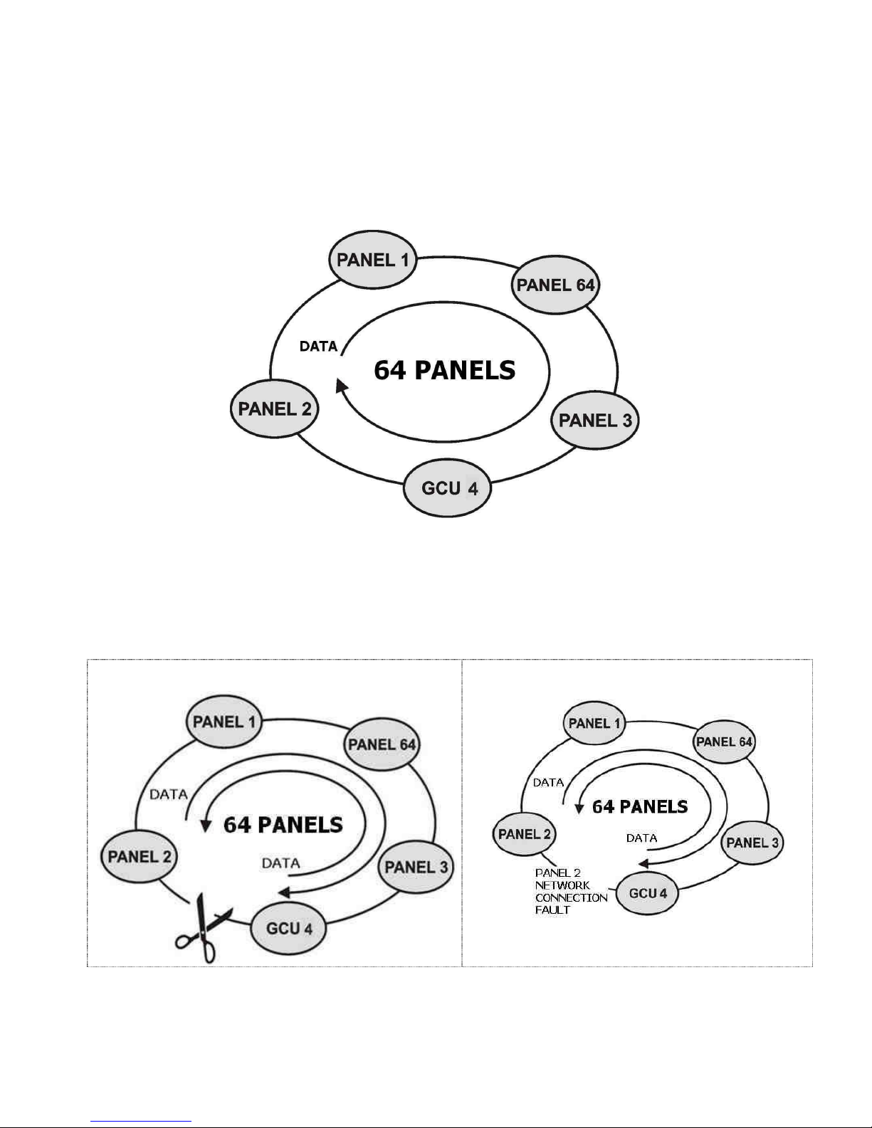
Up to 64 Maxlogic Series Intelligent Analogue Addressable Fire Alarm Control Panels can operate in a
network structure. “16 loops x 127 devices x 64 panels = 130.048 devices” can operate in a network.
KK-641.002 Rev.No:1 01.08.12 ML-121X User Manual Page | 24
All panels in the same network can communicate with each others. An event, which occurs in a panel,
can be seen from every panel in the network. Furthermore, one panel can control other panels (Reset,
Silence Sounder etc.)
All models of Maxlogic Series Fire Alarm Control Panels can operate in the same network.
(ML-121X.N, ML-123X.N, ML-124X.N, ML-125X.N)
** GCU (Gateway Controller) allows the network to be monitored graphically and controlled remotely
from a distant place. GCU connect to the network line as a control panel. The panels must be
connected to each other with FTP Cat6 Network Cable.
(See, Annex-F Network Connection Scheme.)
In case of open circuit (broken line), network continues
operating.
In case of open circuit fault of the network line, the
system can detect the exact point of problem.
Switch Settings on Network Card:
ML-1201 Network Module has 2 switches related to the networking.
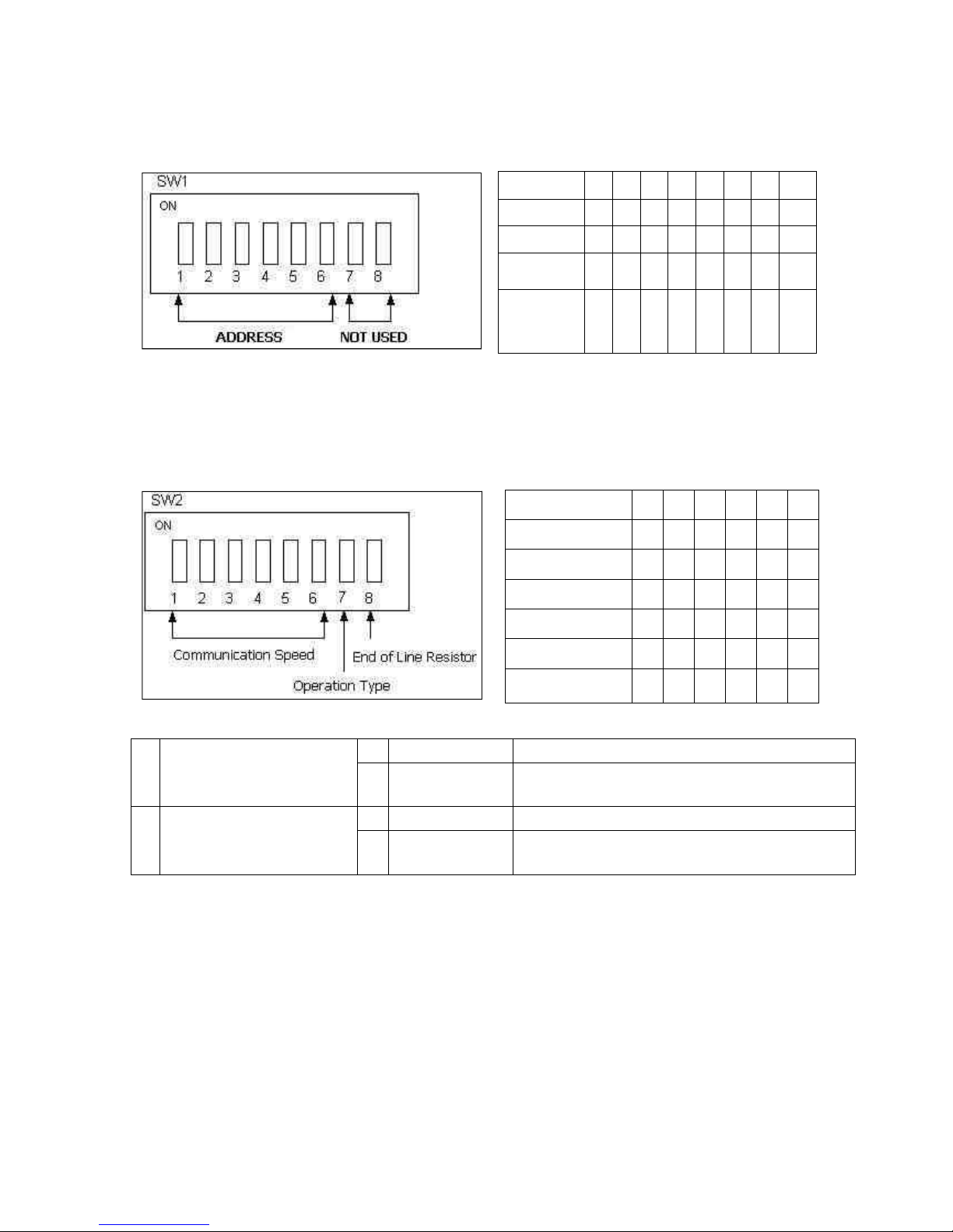
KK-641.002 Rev.No:1 01.08.12 ML-121X User Manual Page | 25
SWITCH 1- Used to set the address of panel in network.
1
0 0 0 0 0 0 0 0
11
0 1 0 1 0 0 0 0 23
0 1 1 0 1 0 0 0
54
1
0
1
0
1
1
0
0
Panel
Address
1
2
3
4
5
6
7
8
SWITCH 2- Used to set the communication speed, operation type and end of line
resistor of Panel which will operate in the network.
250 Kbps
1 0 0 0 0 0
100 Kbps
0 1 0 0 0 0
50 Kbps
0 0 1 0 0 0
20 Kbps
0 0 0 1 0 0 10 Kbps
0 0 0 0 1 0
5 Kbps
0 0 0 0 0 1
Communication
Speed
1
2
3
4
5
6
7
Operation Type
0 Normal Mode
Used for panels and repeater panels
1
Transparent
Mode
Used for signal amplifying distance extender
modules
8
End-of-Line
Resistor
Setting
0 120R disabled
-
1
120R enabled
Used to activate 120R which is the end-of-line
resistor. Always, it must be at this position

KK-641.002 Rev.No:1 01.08.12 ML-121X User Manual Page | 26
13- TECHNICAL SPECIFICATIONS
Loop capacity
:
Sounder outputs
:
Fire alarm relay
:
Alarm relay
:
Fault relay :
Remote controls
:
Operating ambient humidity
:
Auxilary supply output
:
Operating ambient temperature
:
Main power supply :
Operating voltage
:
System fuse
:
Batteries
:
Construction
:
Finish
:
Mounting
:
Standard color
:
Dimensions
:
Weight :
1 to 2 loops
4 x (24 V DC 500 mA), programmable,
Supervised, self –resetting fuse protected,
10 kOhm end-of-line resistor
30 V DC 1 A volt-free contact, programmable
30 V DC 1 A volt-free contact, programmable
30 V DC 1 A volt-free contact, programmable
4 units of programmable inputs
%0-95 (non-condensing)
24 V DC 500 mA self-resetting fuse protected
(-5ºC) - (+50ºC)
230 V AC 50 Hz (5 A glass type fuse) 83 Watt
24 V DC
5 A, glass type fuse
2 x (12 V 7 Ah)
1mm DKP
Epoxy paint
Surface or flush mount
Grey (RAL 7015), white panel front cover
500 x 370 x 110 mm
max. 7.650 kg

KK-641.002 Rev.No:1 01.08.12 ML-121X User Manual Page | 27
14- PANEL MODELS
ML-1210.N
Maxlogic intelligent analogue addressable fire alarm panel, 0 Loop, Network, 230V AC, 50 Hz, 83 Watt, IP30
ML-1211
Maxlogic intelligent analogue addressable fire alarm panel, 1 Loop, 127 Address, 230V AC, 50 Hz, 83 Watt, IP30
ML-1211.N
Maxlogic intelligent analogue addressable fire alarm panel, 1 Loop, 127 Address, Network, 230V AC, 50 Hz,
83 Watt, IP30
ML-1212
Maxlogic intelligent analogue addressable fire alarm panel, 2 Loop, 254 Address, 230V AC, 50 Hz, 83 Watt, IP30
ML-1212.N
Maxlogic intelligent analogue addressable fire alarm panel, 2 Loop, 254 Address, Network, 230V AC, 50 Hz,
83 Watt, IP30

KK-641.002 Rev.No:1 01.08.12 ML-121X User Manual Page | 28
ANNEX-A PANEL DIMENSIONS AND MOUNTING HOLES
Figure 1- Panel Dimensions
Figure 2- Mounting Holes

KK-641.002 Rev.No:1 01.08.12 ML-121X User Manual Page | 29
ANNEX-B CONNECTION SCHEME

KK-641.002 Rev.No:1 01.08.12 ML-121X User Manual Page | 30
ANNEX-C PANEL SPARE PARTS

KK-641.002 Rev.No:1 01.08.12 ML-121X User Manual Page | 31
ANNEX-D SERIAL COMMUNICATION CABLE

KK-641.002 Rev.No:1 01.08.12 ML-121X User Manual Page | 32
ANNEX-E SCHEME OF MENU FUNCTIONS
KK-641.002 Rev.No:1 01.08.12 ML-121X User Manual Page | 33

KK-641.002 Rev.No:1 01.08.12 ML-121X User Manual Page | 34

KK-641.002 Rev.No:1 01.08.12 ML-121X User Manual Page | 35
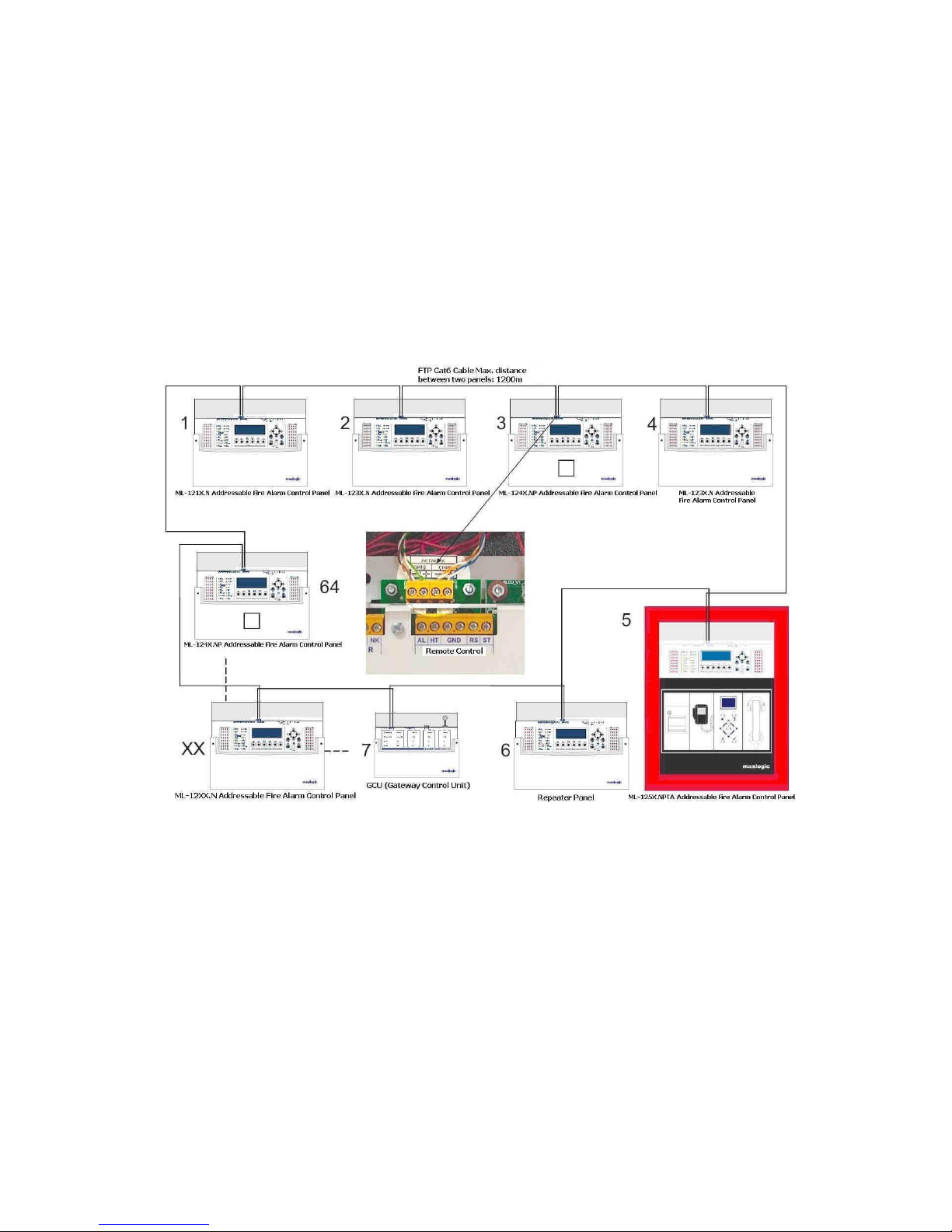
ANNEX-F NETWORK CONNECTION SCHEME
KK-641.002 Rev.No:1 01.08.12 ML-121X User Manual Page | 36
 Loading...