


www.GreenElectricalSupply.com
Operating Instructions WP-OP Series
MaxLite WallMax™ Open Face
• To reduce the risk of death, personal injury or property damage from
fire, electric shock, falling parts, cuts/abrasions, and other hazards
read all warnings and instructions included with and on the fixture
box and all fixture labels.
• Before installing, servicing, or performing routine maintenance upon
this equipment, follow these general precautions.
• Commercial installation, service and maintenance of luminaires
should be performed by a qualified licensed electrician.
• For Residential installation: If you are unsure about the installation or
maintenance of the luminaires, consult a qualified licensed electrician
and check your local electrical code.
• DO NOT INSTALL DAMAGED PRODUCT!
• This fixture is intended to be connected to a properly installed and
grounded UL listed junction box.
WARNING:
RISK OF ELECTRICAL SHOCK
• Turn off electrical power at fuse or circuit breaker box before wiring fixture to the power supply.
• Turn off the power when you perform any maintenance.
• Verify that supply voltage is correct by comparing it with the luminaire label information.
• Make all electrical and grounded connections in accordance with the National Electrical Code
and any applicable local code requirements.
• All wiring connections should be capped with UL approved wire connectors.
• Do not handle energized fixture when hands are wet, when standing on wet or damp surfaces, or in water.
CAUTION:
RISK OF INJURY
• Wear gloves and safety glasses at all times when removing luminaire from carton, installing, servicing
or performing maintenance.
• Avoid direct eye exposure to the light source while it is on.
• Account for small parts and destroy packing material, as these may be hazardous to children.
CAUTION:
RISK OF FIRE
• Keep combustible and other materials that can burn away from luminaire and lamp/lens
• MIN 90°C SUPPLY CONDUCTORS.
Models:
WP-OP28
WP-OP40
WP-OP50
WP-OP80
WP-OP120
Operating characteristic:
Operating Temperature: -30°C to 40°C
Rated Voltage: 120-277 Vac 50/60Hz
© Copyright 2018. MaxLite, Inc. All Rights Reserved.
12 York Ave, West Caldwell, NJ 07006 Tel: 800-555-5629 Fax: 973-244-7333 Email: info@maxlite.com
®
General Safety Information
Page: 1
REV: 8/28/18
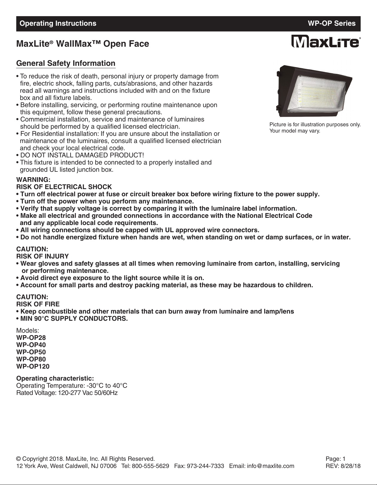
Picture is for illustration purposes only.
Your model may vary.
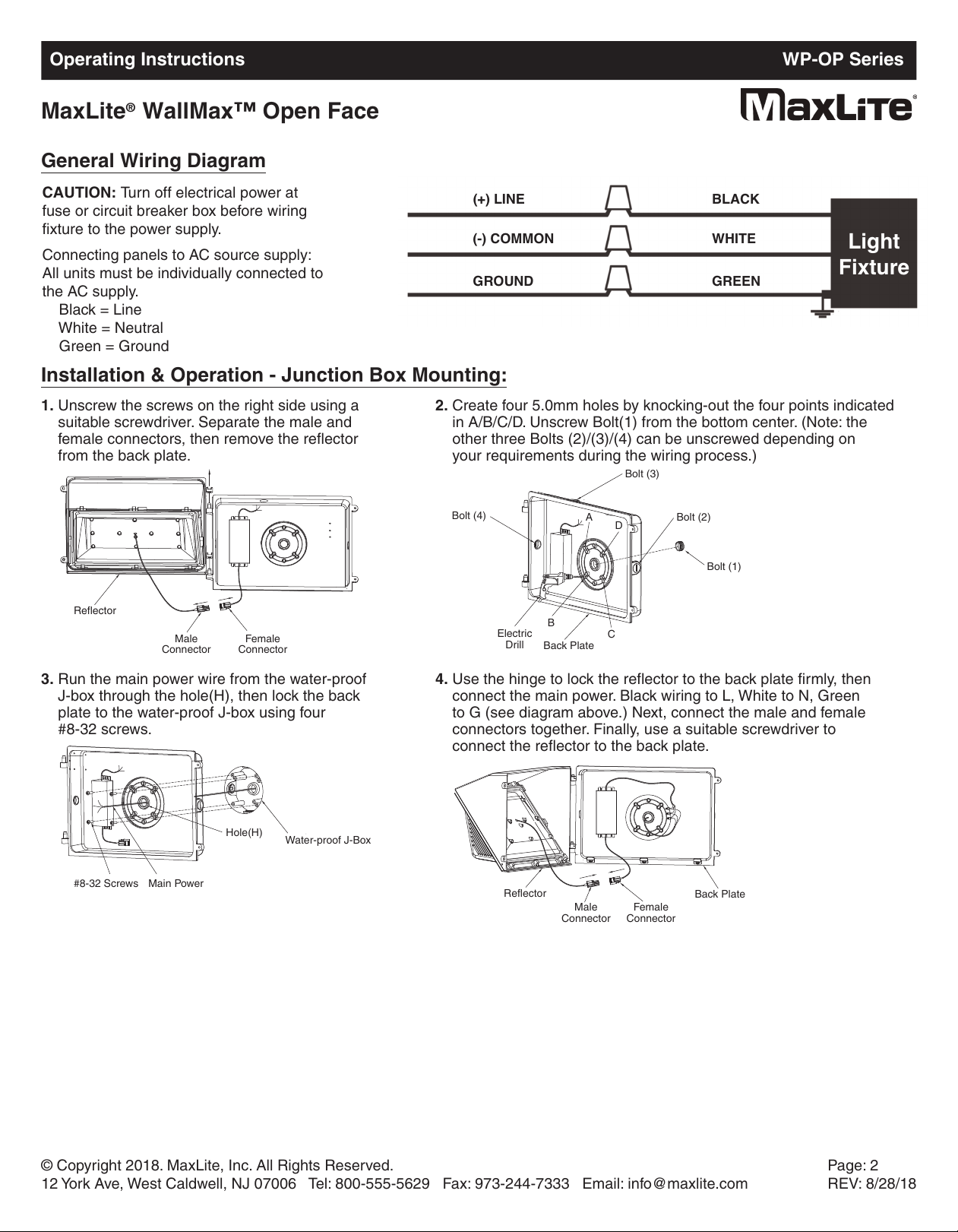
General Wiring Diagram
CAUTION: Turn off electrical power at
f
use or circuit breaker box before wiring
fixture to the power supply.
Connecting panels to AC source supply:
All units must be individually connected to
the AC supply.
Black = Line
White = Neutral
Green = Ground
Installation & Operation - Junction Box Mounting:
1. Unscrew the screws on the right side using a
suitable screwdriver. Separate the male and
female connectors, then remove the reflector
from the back plate.
2. Create four 5.0mm holes by knocking-out the four points indicated
in A/B/C/D. Unscrew Bolt(1) from the bottom center. (Note: the
other three Bolts (2)/(3)/(4) can be unscrewed depending on
your requirements during the wiring process.)
3. Run the main power wire from the water-proof
J-box through the hole(H), then lock the back
plate to the water-proof J-box using four
#8-32 screws.
4. Use the hinge to lock the reflector to the back plate firmly, then
connect the main power. Black wiring to L, White to N, Green
to G (see diagram above.) Next, connect the male and female
connectors together. Finally, use a suitable screwdriver to
connect the reflector to the back plate.
© Copyright 2018. MaxLite, Inc. All Rights Reserved.
12 York Ave, West Caldwell, NJ 07006 Tel: 800-555-5629 Fax: 973-244-7333 Email: info@maxlite.com
Page: 2
REV: 8/28/18
(+) LINE
(
-) COMMON
GROUND GREEN
W
HITE
BLACK
Light
Fixture
Reflector
Male
Connector
Female
Connector
Bolt (4)
B
olt (3)
Bolt (2)
Bolt (1)
Back Plate
Electric
Drill
#8-32 Screws Main Power
Hole(H)
Water-proof J-Box
Reflector
Male
Connector
Female
Connector
Back Plate
A
D
C
B
Operating Instructions WP-OP Series
MaxLite WallMax™ Open Face
®

Installation & Operation - Conduit Mounting:
1. Unscrew the screws on the right side using a
suitable screwdriver. Separate the male and
female connectors, then remove the reflector
f
rom the back plate.
2. Unscrew the right-side Bolt(5). Drill three 6.5mm holes in E/F/G
using a suitable drill. Next, fasten the back plate to the wall with
the three screw components.
3. Run the main power through the right hole and
then finish the wiring (Black wire - L, White wire -
N, Green wire - G) See wiring diagram on page 2.
4. Use the hinge to lock the reflector to the back plate firmly. Next,
connect the male and female connectors together. Finally, use a
suitable screwdriver to connect the reflector to the back plate.
Note: If the Wall pack has an internal emergency driver, use the 2nd installation instructions - Conduct Mounting.
© Copyright 2018. MaxLite, Inc. All Rights Reserved.
12 York Ave, West Caldwell, NJ 07006 Tel: 800-555-5629 Fax: 973-244-7333 Email: info@maxlite.com
Page: 3
REV: 8/28/18
S
crew
Components
Bolt (5)
R
eflector
M
ale
Connector
F
emale
Connector
B
ack Plate
M
ain Power
E
GF
Emergency Battery Backup Wiring Diagram
BATTERY
LINE
WHITE (COMMON)
BLACK
WHITE/BLACK
RED (+)
RED (+)
BLUE (-)
DRIVER MUST
BE GROUNDED
LED DRIVER
F
H
S
2
-
U
N
V
-
5
6
S
LED ARRAY
WALL
SWITCH
BLACK
WHITE
TEST
SWITCH
BLACK
RED
HOT(100-277VAC)
Operating Instructions WP-OP Series
MaxLite WallMax™ Open Face
®

Photocell Diagram
1. The Red wire (Photocell) connects to Black wire (Driver AC)
2. The White wire (Photocell) connects to White wire (Driver AC) and White N (Main Power)
3. The Black wire (Photocell) connects to Black L (Main Power)
4. Green wire (Driver AC) connects to Green G (Main Power)
© Copyright 2018. MaxLite, Inc. All Rights Reserved.
12 York Ave, West Caldwell, NJ 07006 Tel: 800-555-5629 Fax: 973-244-7333 Email: info@maxlite.com
Page: 4
REV: 8/28/18
Black
(L)
White
(N)
Green
(G)
Photocell
Red
Black
White
Green
White
Black
Driver
Neutral
AC
Operating Instructions WP-OP Series
MaxLite WallMax™ Open Face
®

PIR Occupancy Sensor Wiring Diagram
Note: For additional information on the occupancy sensor see:
https://www.maxlite.com/products/analog-sensors-stand-alone
© Copyright 2018. MaxLite, Inc. All Rights Reserved.
12 York Ave, West Caldwell, NJ 07006 Tel: 800-555-5629 Fax: 973-244-7333 Email: info@maxlite.com
Page: 5
REV: 8/28/18
Non-Dimming
Load
Dimming
Load
Violet
Gray
Load
(Red)
Black
L
i
n
e
o
r
P
h
a
s
e
A
N
e
u
t
r
a
l
o
r
P
h
a
s
e
B
N
e
u
t
r
a
l
o
r
P
h
a
s
e
B
W
h
i
t
e
w
i
t
h
B
l
a
c
k
S
t
r
i
p
e
s
N
e
u
t
r
a
l
o
r
P
h
a
s
e
B
W
h
i
t
e
w
i
t
h
B
l
a
c
k
S
t
r
i
p
e
s
N
e
u
t
r
a
l
o
r
P
h
a
s
e
B
Black
L
i
n
e
o
r
P
h
a
s
e
A
Load
(Red)
Dim (+)
Violet
Dim (-)
Gray
Operating Instructions WP-OP Series
MaxLite WallMax™ Open Face
®

MaxLite Inc. warrants its products for a minimum period of TEN (10) years from the date of original purchase from
MaxLite or its authorized distributor/dealer (the “Warranty Period”), as follows: If a Product fails to operate during the
Warranty Period as a result of defects in materials or workmanship, MaxLite will, at its option, repair it, replace it with
the same or like Product.
Please refer to Maxlite’s website (at http://maxlite.com/resources/warranties) for the complete
terms and conditions of our warranty.
Limitation of Liability
THE FOREGOING WARRANTY IS EXCLUSIVE, AND IS THE SOLE REMEDY FOR ANY AND ALL CLAIMS,
WHETHER IN CONTRACT, IN TORT OR OTHERWISE ARISING FROM THE FAILURE OF PRODUCT AND IS IN
LIEU OF ALL OTHER WARRANTIES, EXPRESS OR IMPLIED, INCLUDING ALL WARRANTIES OF
MERCHANTABILITY OR FITNESS FOR A PARTICULAR PURPOSE, WHICH WARRANTIES ARE HEREBY
EXPRESSLY DISCLAIMED TO THE EXTENT PERMITTED BY LAW AND, IN ANY EVENT, SHALL BE LIMITED TO
THE WARRANTY PERIOD SPECIFIED ABOVE. THE LIABILITY OF MAXLITE SHALL BE LIMITED TO THE TERMS
OF THE EXPRESS WARRANTY SET FORTH HEREIN. IN NO EVENT WILL MAXLITE BE LIABLE FOR ANY
SPECIAL, INCIDENTAL OR CONSEQUENTIAL DAMAGES INCLUDING, WITHOUT LIMITATION, DAMAGES
RESULTING FROM LOSS OF USE, PROFITS, BUSINESS OR GOODWILL, LABOR COSTS, REMOVAL OR
INSTALLATION COSTS, DECREASE IN THE LIGHT OUTPUT OF THE LAMP, AND/OR DETERIORATION IN THE
LAMP’S PERFORMANCE, WHETHER OR NOT MAXLITE HAS BEEN ADVISED OF THE POSSIBILITY THEREOF.
UNDER NO CIRCUMSTANCES SHALL MAXLITE’S ENTIRE LIABILITY FOR A DEFECTIVE PRODUCT EXCEED
THE PURCHASE PRICE OF THAT PRODUCT. WARRANTY SERVICES PROVIDED UNDER THESE TERMS AND
CONDITIONS DO NOT ENSURE THE UNINTERRUPTED OPERATION OF PRODUCTS; MAXLITE SHALL NOT BE
LIABLE FOR DAMAGES CAUSED BY ANY DELAYS INVOLVING WARRANTY SERVICE.
This Limited Warranty gives you specific legal rights and you may also have other rights that may vary from state to
state. Because some states or jurisdictions do not allow the exclusion or limitation of liability for consequential or
incidental damages, this limitation may not apply to you.
Warranty Information
© Copyright 2018. MaxLite, Inc. All Rights Reserved.
12 York Ave, West Caldwell, NJ 07006 Tel: 800-555-5629 Fax: 973-244-7333 Email: info@maxlite.com
Page: 6
REV: 8/28/18
Operating Instructions WP-OP Series
MaxLite WallMax™ Open Face
®
 Loading...