

MaxLite StaxMax Instructions Manual
© Copyright 2014. MaxLite, Inc. All Rights Reserved.
Rev: 6/20/2014
Operating Instructions
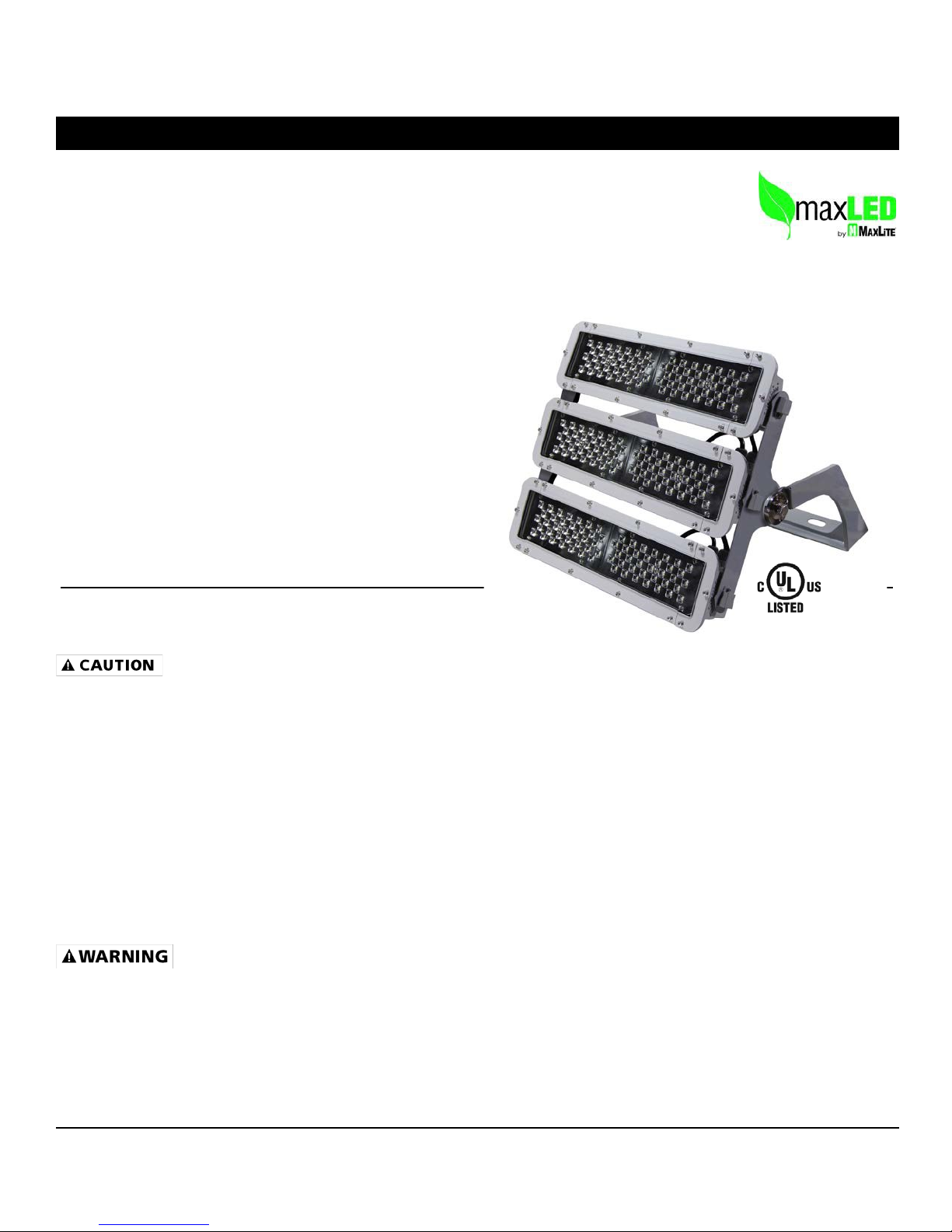
MaxLite® StaxMax™
LED Flood Lights
Input Rating
120V-277V 50/60Hz
(347/480v optional)
Wet Location Rated
IP65
Operating temperature
-22⁰F to 122⁰F
General Safety Information
1. READ AND FOLLOW ALL SAFETY INSTRUCTIONS.
2. Review the diagrams thoroughly before beginning.
3. All electrical connections must be in accordance with local codes, ordinance, and the National Electric Code.
If you are unfamiliar with methods of installing electrical wiring, secure the services of a qualified licensed
electrician.
4. Before starting the installation, disconnect the power by turning off the circuit breaker or by removing the
appropriate fuse at the fuse box. Turning the power off using the light switch is not sufficient to prevent
electrical shock.
5. Equipment should be mounted in location and at heights where it will not readily be subject to tampering by
unauthorized personnel.
7. Do not use this equipment for other than intended use.
8. All servicing should be performed by qualified personnel only.
1. WARNING - Risk of fire or electric shock. Install this flood only in the luminaires that has the construction
features and dimensions shown in the photographs and/or drawings.
2. WARNING - Do not make or alter any open holes in an enclosure of wiring or electrical components during
MaxLite® StaxMax™ LED Flood Lights installation
3. WARNING - Risk of fire or electric shock. MaxLite® StaxMax™ LED Flood Lights installation requires
knowledge of the lighting luminaires electrical systems. If not qualified, do not attempt installation. Contact
qualified electrician.
12 York Ave, West Caldwell, NJ 07006 Tel: 973-244-7300 Fax: 973-244-7333 Email: info@maxlite.com
© Copyright 2014. MaxLite, Inc. All Rights Reserved.
Rev: 6/20/2014
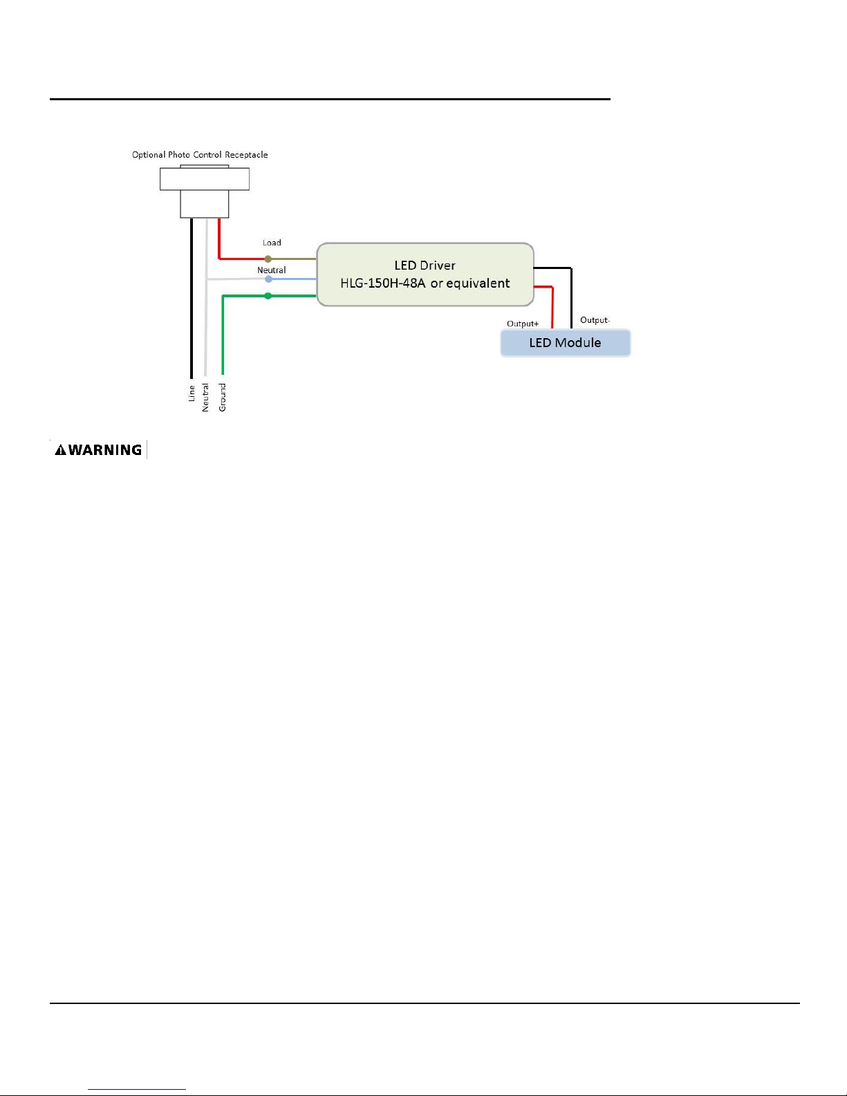
MaxLite® StaxMax™ LED Flood Lights Driver Wiring Diagram
Single Hea d:
1. All units must be individually connected to the AC supply (120-277 VAC):
Black = Line
White = Neutral
Green= Ground
2. Line connection to be made to switch lead from source.
Driver Replacements: Contact your local MaxLite® representative or MaxLite® to receive replacements
for drivers.
Step 1: Disconnect the power by turning off the
circuit breaker or by removing the appropriate
fuse at the fuse box.
*Turning the power off using the light switch is not
sufficient to prevent electrical shock.
Step 2: Disconnect the black LED Module
connector to disconnect Module from driver.
Step 3: Remove four (4) screws and front plate
from connector box to expose wire connections.
Step 4: Disconnect all wiring connections.
Step 5: Loosen up nylon liquid tight strain relief
fitting to remove driver cord.
Step 6: Unscrew two (2) screws to remove
driver cover.
Step 7: Remove four (4) screws to dismount
driver from driver plate.
Step 8: Remove screw for strain relief clip
attached to mounting bracket of driver plate.
Step 9: Replace with new driver.
Step 10: Reverse steps 9 to 3 to assemble
fixture.
Step 11: Restore Power.
12 York Ave, West Caldwell, NJ 07006 Tel: 973-244-7300 Fax: 973-244-7333 Email: info@maxlite.com
© Copyright 2014. MaxLite, Inc. All Rights Reserved.
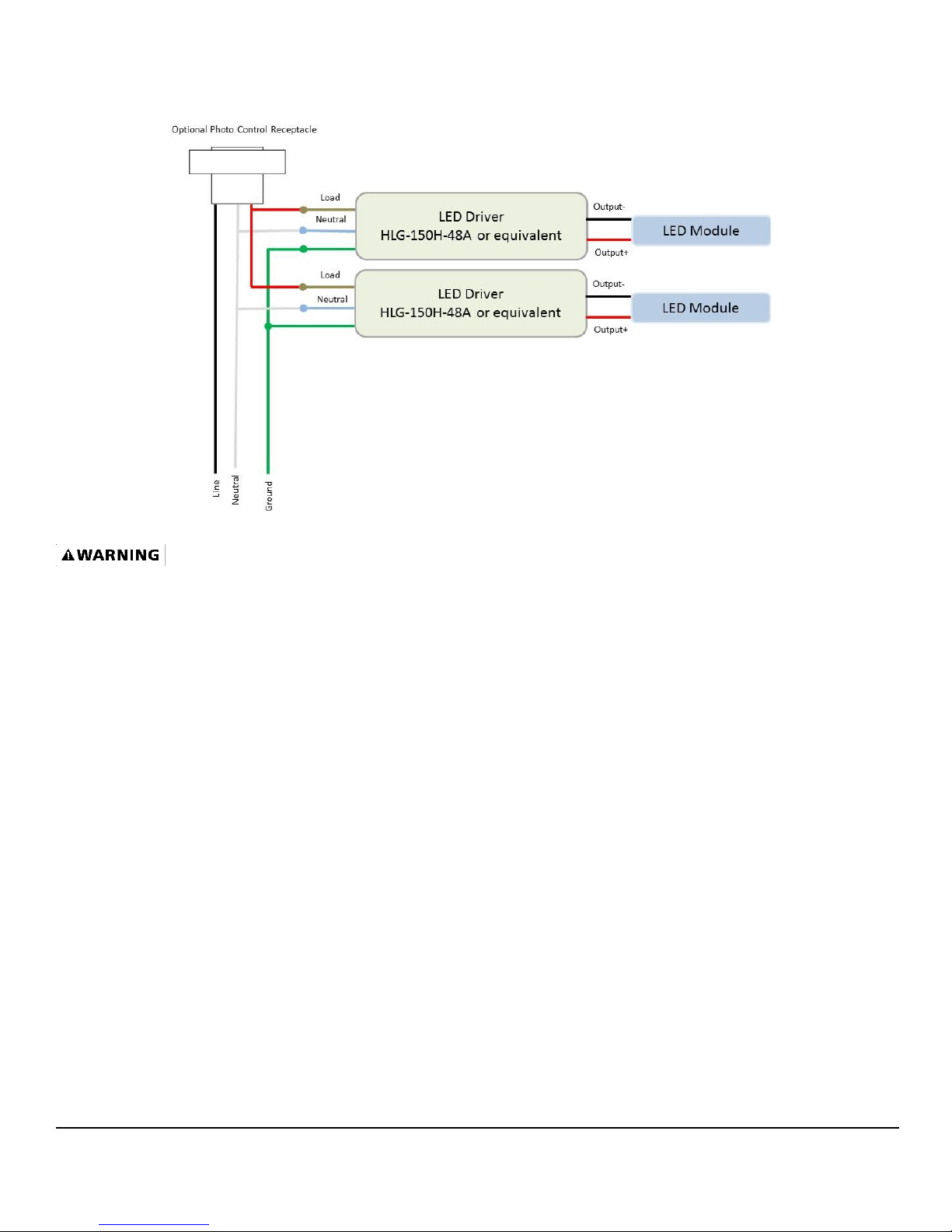
Double Head:
Rev: 6/20/2014
1. All units must be individually connected to the AC supply (120-277 VAC):
Black = Line
White = Neutral
Green= Ground
2. Line connection to be made to switch lead from source.
Driver Replacements: Contact your local MaxLite® representative or MaxLite® to receive replacements
for drivers.
Step 1: Disconnect the power by turning off the
circuit breaker or by removing the appropriate
fuse at the fuse box.
*Turning the power off using the light switch is not
sufficient to prevent electrical shock.
Step 2: Disconnect the black LED Module
connector to disconnect Module from driver.
Step 3: Remove four (4) screws and front plate
from connector box to expose wire connections.
Step 4: Disconnect all wiring connections.
Step 5: Loosen up nylon liquid tight strain relief
fitting to remove driver cord.
Step 6: Unscrew two (2) screws to remove
driver cover.
Step 7: Remove four (4) screws to dismount
driver from driver plate.
Step 8: Remove screw for strain relief clip
attached to mounting bracket of driver plate.
Step 9: Replace with new driver.
Step 10: Reverse steps 9 to 3 to assemble
fixture.
Step 11: Restore Power.
12 York Ave, West Caldwell, NJ 07006 Tel: 973-244-7300 Fax: 973-244-7333 Email: info@maxlite.com
 Loading...