

Page 1
© Copyright 2018. MaxLite, Inc. All Rights Reserved.
12 York Ave, West Caldwell, NJ 07006 Tel: 800-555-5629 Fax: 973-244-7333 Email: [email protected]
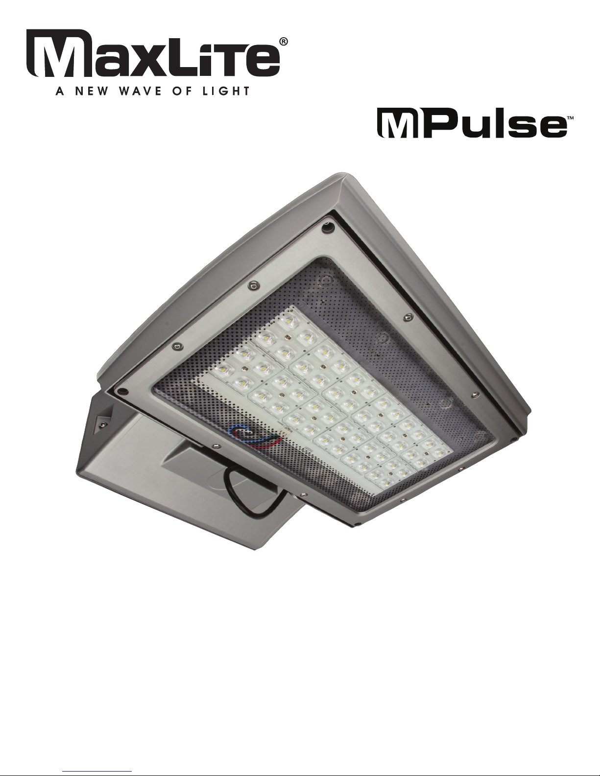
Installation Manual
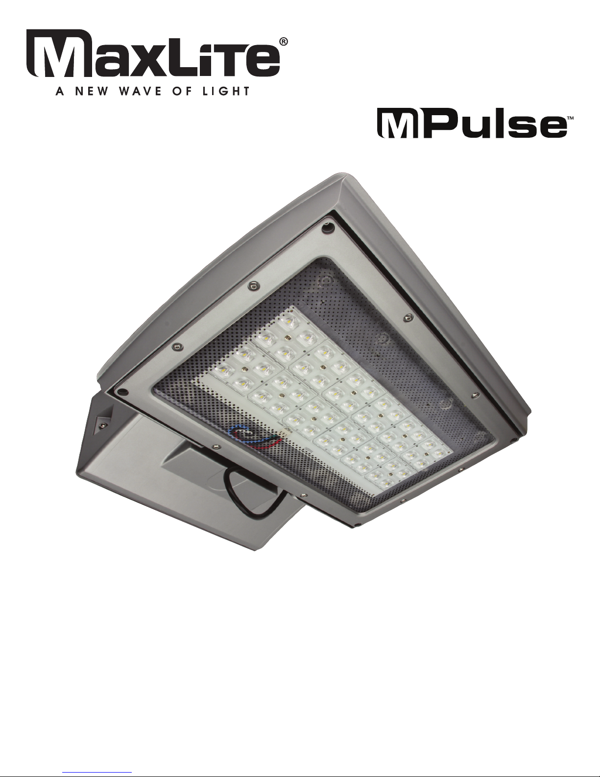
MPulse Adjustable
Wall Mount Luminaire
REV: 2/07/18
Page 2
BEFORE YOU BEGIN
Read these instructions completely and carefully.
WARNING
Risk of fire or electric shock. Luminaire wiring and electrical parts may be damaged when drilling for
installation of led retrofit kit, check for enclosed wiring and components.
To prevent wiring damage or abrasion, do not expose wiring to edges of sheet metal or other sharp objects.
General Safety Information
• To reduce the risk of death, personal injury or property damage from
fire, electric shock, falling parts, cuts/abrasions, and other hazards
read all warnings and instructions included with and on the fixture
box and all fixture labels.
• Before installing, servicing, or performing routine maintenance upon
this equipment, follow these general precautions.
• Commercial installation, service and maintenance of luminaires
should be performed by a qualified licensed electrician.
• DO NOT INSTALL DAMAGED PRODUCT!
• This fixture is intended to be connected to a properly installed and
grounded UL listed junction box.
WARNING:
RISK OF ELECTRICAL SHOCK
• Turn off electrical power at fuse or circuit breaker box before wiring fixture to the power supply.
• Turn off the power when you perform any maintenance.
• Verify that supply voltage is correct by comparing it with the luminaire label information.
• Make all electrical and grounded connections in accordance with the National Electrical Code
and any applicable local code requirements.
• All wiring connections should be capped with UL approved wire connectors.
CAUTION:
RISK OF INJURY
• Unit will fall if not installed properly. Follow installation instructions.
• Wear gloves and safety glasses at all times when removing luminaire from carton, installing, servicing
or performing maintenance.
• Avoid direct eye exposure to the light source while it is on.
• Account for small parts and destroy packing material, as these may be hazardous to children.
CAUTION:
RISK OF FIRE
• Keep combustable and other materials that can burn away from luminaire and lamp/lens
• MIN 90°C SUPPLY CONDUCTORS.
Input Rating: 120V-277V 50/60Hz
Operating Temperature: -40°F to 104°F
Illustrations in the manual are for installation purposes only. It may not be identical to the fixture purchased.
Models:
This instruction manual applies to the MP-SM Series
© Copyright 2018. MaxLite, Inc. All Rights Reserved.
12 York Ave, West Caldwell, NJ 07006 Tel: 800-555-5629 Fax: 973-244-7333 Email: [email protected]
Page 3
© Copyright 2018. MaxLite, Inc. All Rights Reserved.
12 York Ave, West Caldwell, NJ 07006 Tel: 800-555-5629 Fax: 973-244-7333 Email: [email protected]
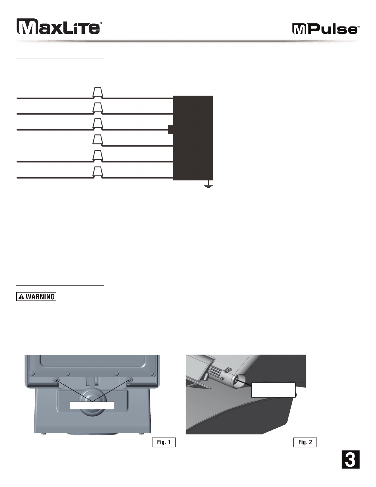
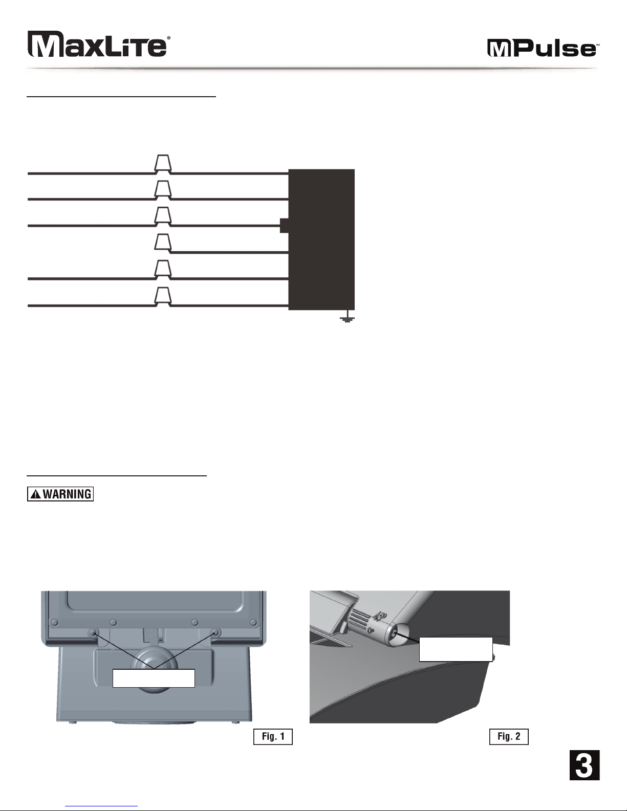
General Wiring Diagram
CAUTION: Turn off electrical power at fuse or circuit breaker box before wiring fixture to the power supply.
Installation & Operation
Disconnect the power by turning off the circuit breaker or by removing the appropriate fuse at the fuse box.
Turning the power off using the light switch is not sufficient to prevent electrical shock.
1. The fixture should be set at a full cutoff 0° angle. If this angle is desired, skip to step 5. If another angle is
desired (either 15°, 30°, or 45°) remove the two front hex screws (Figure 1).
2. Loosen the adjustment screws (Figure 2) on the side of the fixture.
0-10V Dimmable Wiring:
1.) Connect the black fixture wire to the HOT LINE supply wire.
2.) Connect the white fixture wire to the NEUTRAL supply wire.
3.) Connect the green fixture wire to supply ground wire.
4.) Cap the YELLOW wire.
5.) Connect the purple fixture wire to the (V+) DIM wire.
6.) Connect the gray fixture wire to the (V-) DIM wire.
HOT
NEUTRAL
GROUND GREEN
WHITE
BLACK
Light
Fixture
YELLOW
(+) DIM V+ PURPLE
(-) DIM V- GRAY
Front Hex Screws
Head Adjustment
Screw
Page 4
© Copyright 2018. MaxLite, Inc. All Rights Reserved.
12 York Ave, West Caldwell, NJ 07006 Tel: 800-555-5629 Fax: 973-244-7333 Email: [email protected]
Installation & Operation (Continued)
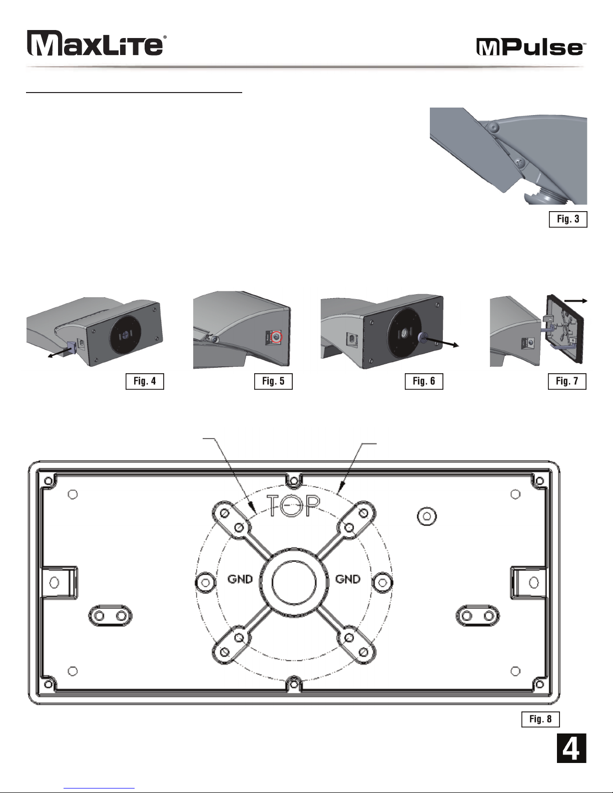
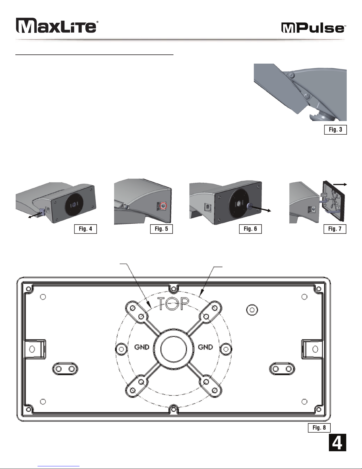
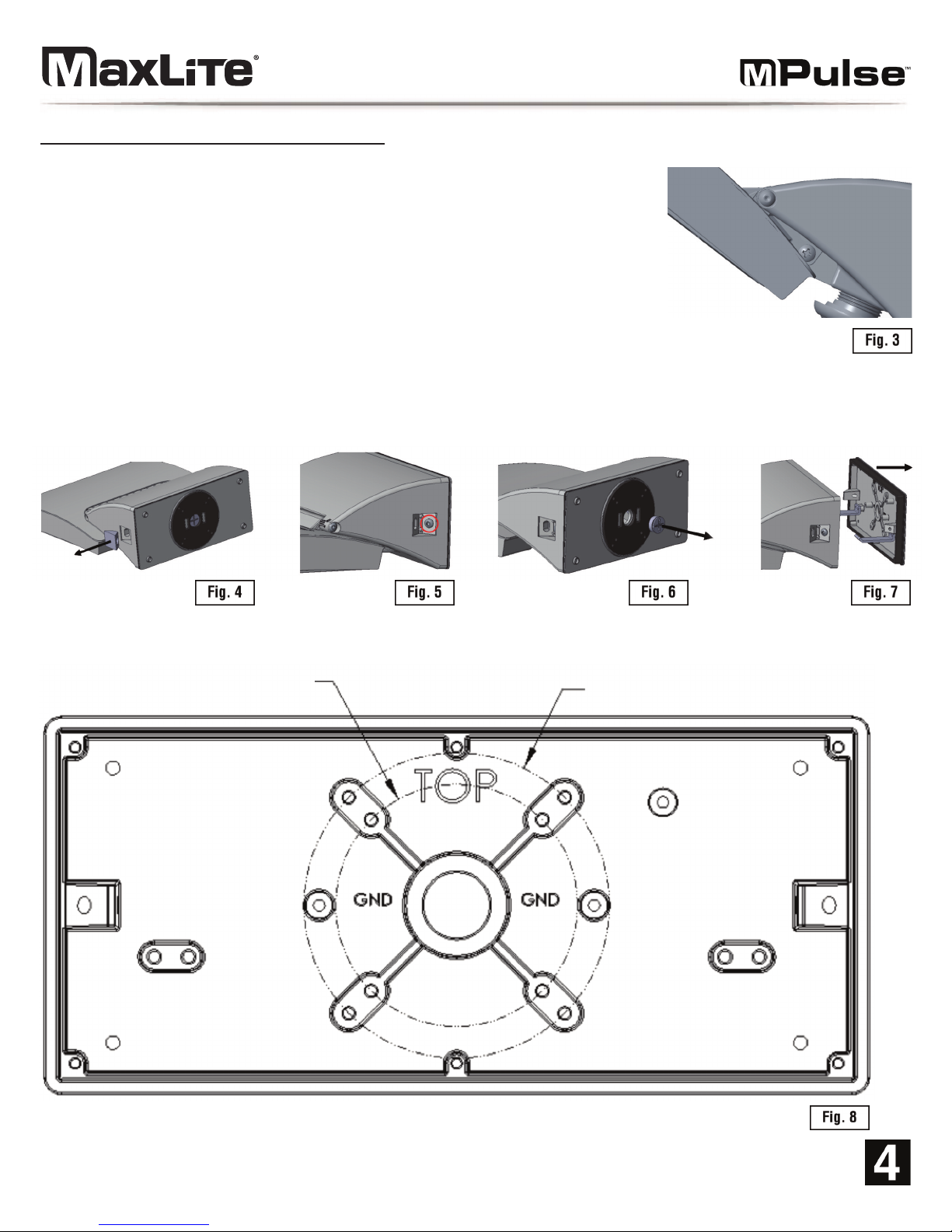
3. Tilt the head to the desired angle (15°, 30°, or 45°). The holes in the two center
brackets should align based on which angle is trying to be achieved. Lock the
head in place using the included Philips head screw (Figure 3). It is
recommended to use a long Philips screw driver (at least 8” from the base)
and enter from the side of the fixture when securing the screw.
4. Re-tighten the adjustment screws on the side of the fixture.
5. Use a flat head screwdriver to remove the two rubber plugs from the
sides of the driver box (Figure 4).
6. Remove the screws from the sides of the driver box using an M4 hex key (Figure 5).
7. Use a flat head screwdriver to unscrew the cap from the back of the driver box mounting plate (Figure 6).
8. Separate the back mounting plate from the driver box. A flat head screwdriver may be needed to remove the
back mounting plate from the driver box (Figure 7).
9. Drill mounting holes in the mounting plate following the template as shown. Drill through the raised hole locations
that correspond to the mounting points on the intended junction box (Figure 8):
Ø 2.774”
[70.46]
Ø 3.500”
[88.9]
Page 5
Installation & Operation (Continued)
© Copyright 2018. MaxLite, Inc. All Rights Reserved.
12 York Ave, West Caldwell, NJ 07006 Tel: 800-555-5629 Fax: 973-244-7333 Email: [email protected]
10. Fasten the mounting plate to the junction box in the wall with screws.
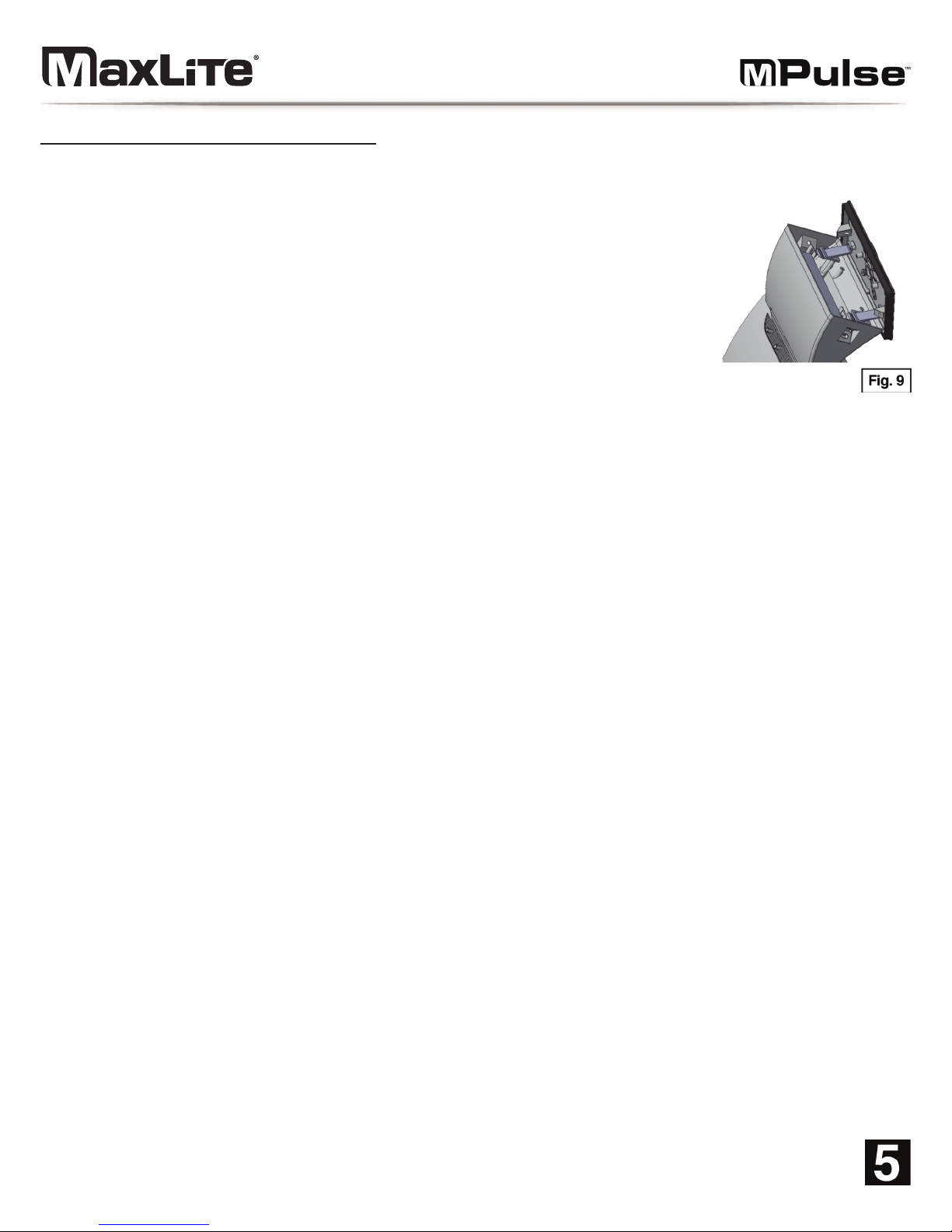
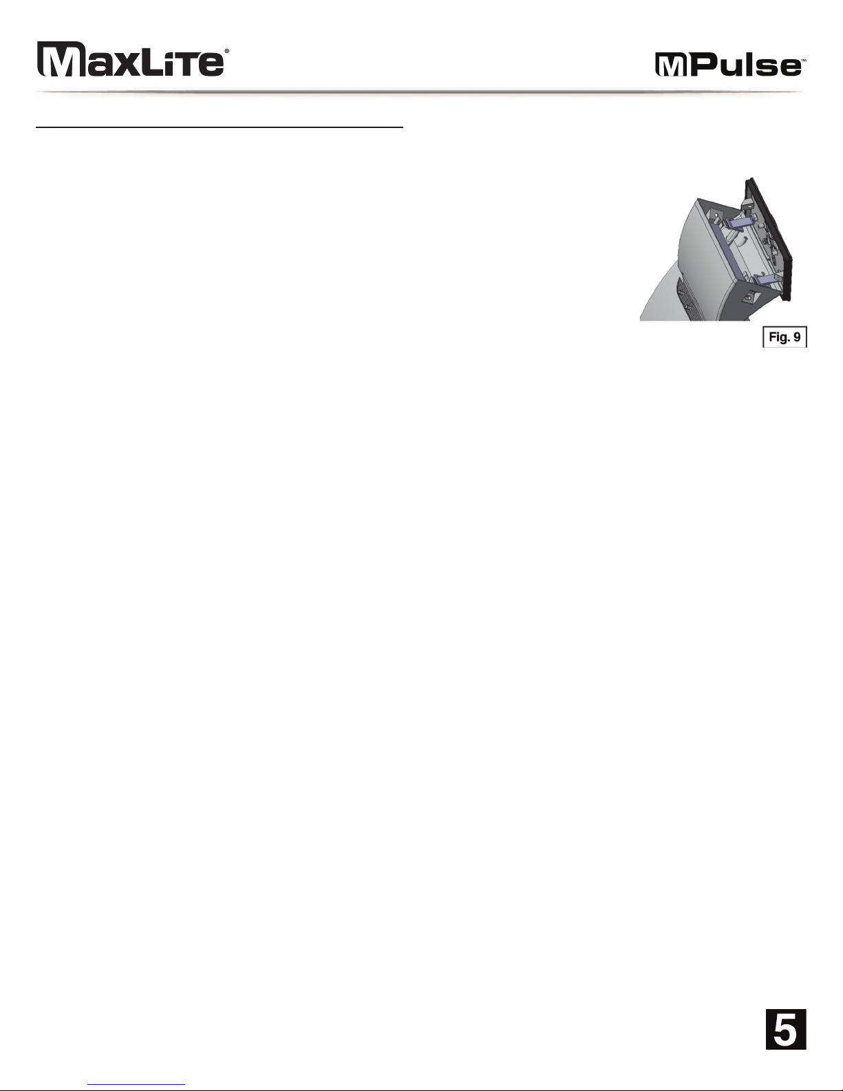
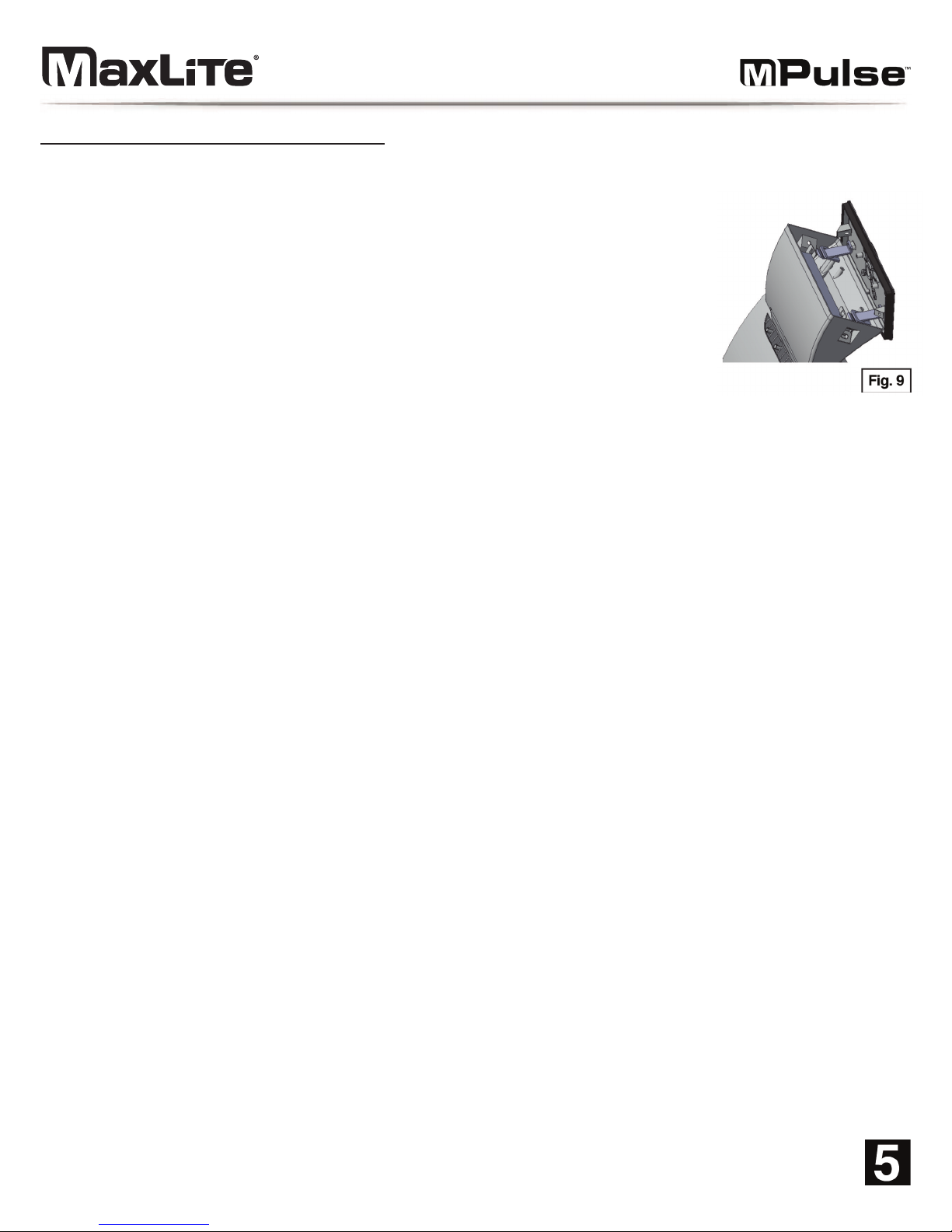
11. Hook the driver box onto the mounting plate. Allow the fixture to hang by the
hooks, to facilitate the wiring process (Figure 9).
12. Pull the wires through the hole in the mounting plate and complete the wiring
connections following the wiring diagram (See wiring diagram on page 3):
13. Replace the driver box onto the mounting plate. Ensure that the gasket around
the mounting plate fits in place. Secure the driver box to the mounting plate using
the screws on the sides of the driver box.
14. Cover the side screws with the rubber plugs.
Page 6
© Copyright 2018. MaxLite, Inc. All Rights Reserved.
12 York Ave, West Caldwell, NJ 07006 Tel: 800-555-5629 Fax: 973-244-7333 Email: [email protected]
MaxLite Inc. warrants its products for a minimum period of TEN (10) years from the date of original purchase from
MaxLite or its authorized distributor/dealer (the “Warranty Period”), as follows: If a Product fails to operate during the
Warranty Period as a result of defects in materials or workmanship, MaxLite will, at its option, repair it, replace it with
the same or like Product.
Please refer to Maxlite’s website (at http://maxlite.com/resources/warranties) for the complete
terms and conditions of our warranty.
Limitation of Liability
THE FOREGOING WARRANTY IS EXCLUSIVE, AND IS THE SOLE REMEDY FOR ANY AND ALL CLAIMS,
WHETHER IN CONTRACT, IN TORT OR OTHERWISE ARISING FROM THE FAILURE OF PRODUCT AND IS IN
LIEU OF ALL OTHER WARRANTIES, EXPRESS OR IMPLIED, INCLUDING ALL WARRANTIES OF
MERCHANTABILITY OR FITNESS FOR A PARTICULAR PURPOSE, WHICH WARRANTIES ARE HEREBY
EXPRESSLY DISCLAIMED TO THE EXTENT PERMITTED BY LAW AND, IN ANY EVENT, SHALL BE LIMITED TO
THE WARRANTY PERIOD SPECIFIED ABOVE. THE LIABILITY OF MAXLITE SHALL BE LIMITED TO THE TERMS
OF THE EXPRESS WARRANTY SET FORTH HEREIN. IN NO EVENT WILL MAXLITE BE LIABLE FOR ANY
SPECIAL, INCIDENTAL OR CONSEQUENTIAL DAMAGES INCLUDING, WITHOUT LIMITATION, DAMAGES
RESULTING FROM LOSS OF USE, PROFITS, BUSINESS OR GOODWILL, LABOR COSTS, REMOVAL OR
INSTALLATION COSTS, DECREASE IN THE LIGHT OUTPUT OF THE LAMP, AND/OR DETERIORATION IN THE
LAMP’S PERFORMANCE, WHETHER OR NOT MAXLITE HAS BEEN ADVISED OF THE POSSIBILITY THEREOF.
UNDER NO CIRCUMSTANCES SHALL MAXLITE’S ENTIRE LIABILITY FOR A DEFECTIVE PRODUCT EXCEED
THE PURCHASE PRICE OF THAT PRODUCT. WARRANTY SERVICES PROVIDED UNDER THESE TERMS AND
CONDITIONS DO NOT ENSURE THE UNINTERRUPTED OPERATION OF PRODUCTS; MAXLITE SHALL NOT BE
LIABLE FOR DAMAGES CAUSED BY ANY DELAYS INVOLVING WARRANTY SERVICE.
This Limited Warranty gives you specific legal rights and you may also have other rights that may vary from state to
state. Because some states or jurisdictions do not allow the exclusion or limitation of liability for consequential or
incidental damages, this limitation may not apply to you.
Warranty Information
Page 7

© Copyright 2018. MaxLite, Inc. All Rights Reserved.
12 York Ave, West Caldwell, NJ 07006 Tel: 800-555-5629 Fax: 973-244-7333 Email: [email protected]
Page 8

© Copyright 2018. MaxLite, Inc. All Rights Reserved.
12 York Ave, West Caldwell, NJ 07006 Tel: 973-244-7300 Fax: 973-244-7333 Email: [email protected]
Page 9
© Copyright 2018. MaxLite, Inc. Todos los derechos reservados.
12 York Ave, West Caldwell, NJ 07006 Tel: 800-555-5629 Fax: 973-244-7333 Correo electrónico: [email protected]
Manual de instalación
Luminaria para montaje
en pared ajustable MPulse
REV: 07/02/2018
Page 10
ANTES DE COMENZAR
Lea estas instrucciones por completo y detenidamente.
ADVERTENCIA
Riesgo de incendio o de descarga eléctrica. Para instalar el equipo de LED retrofit, es necesario taladrar por lo
que el cableado de la luminaria y las partes eléctricas pueden sufrir daños.
Para evitar el daño o la abrasión del cableado, no exponga el cableado a bordes de chapa u otros objetos filosos.
Información general sobre seguridad
• Lea todas las advertencias e instrucciones que se incluyen dentro y fuera de la caja del dispositivo,
y en las etiquetas, para así reducir el riesgo de muerte, lesiones personales o daños a la propiedad
a causa de incendio, descarga eléctrica, piezas que caen y otros riesgos.
• Antes de instalar, reparar o realizar mantenimiento de rutina a este equipo,
siga estas precauciones generales.
• Un electricista matriculado calificado debe realizar las instalaciones comerciales,
servicios y mantenimiento de las luminarias.
• SI EL PRODUCTO ESTÁ DAÑADO, NO LO INSTALE!
• Este dispositivo está destinado para ser conectado en una caja de conexiones
debidamente instalada y con conexión a tierra, con certificación UL.
ADVERTENCIA:
RIESGO DE DESCARGA ELÉCTRICA
• Desconecte la energía eléctrica desde la caja de fusibles o disyuntor antes de conectar el cableado del
dispositivo al suministro eléctrico.
• Desconecte la energía eléctrica antes de realizar cualquier mantenimiento.
• Compare el voltaje del suministro con la información de la etiqueta de la luminaria y verifique que sea
correcto.
• Realice todas las conexiones eléctricas y con conexión a tierra de acuerdo con el Código Eléctrico
Nacional y con todos los requisitos de códigos locales que apliquen.
• Todas las conexiones de cableado deben terminar con conectores de cable con certificación UL.
PRECAUCIÓN :
RIESGO DE LESIONES
• La unidad se caerá si no se encuentra correctamente instalada. Siga las instrucciones de instalación.
• Al quitar las luminarias del cartón, al instalarlas, repararlas o al realizar el mantenimiento, use guantes y
gafas de seguridad en todo momento.
• Evite mirar directamente a la fuente de luz mientras esté encendida.
• Cuente las partes pequeñas y destruya todo el material de embalaje, ya que podrían ser peligrosos para los niños.
PRECAUCIÓN:
RIESGO DE INCENDIO
• Mantenga aquellos materiales inflamables y otros materiales que puedan quemarse, alejados de las
luminarias y de las lámparas u ópticas.
• CONDUCTORES DE SUMINISTRO DE MÍN. 90 °C.
Capacidad nominal de entrada: 120 V-277 V 50/60 Hz
Temperatura de funcionamiento: -40 °F a 104 °F
El propósito de las ilustraciones en este manual es para realizar la instalación. Puede que no sean idénticas al dispositivo adquirido.
Modelos:
Este manual de instrucciones aplica a la serie MP-SM
© Copyright 2018. MaxLite, Inc. Todos los derechos reservados.
12 York Ave, West Caldwell, NJ 07006 Tel: 800-555-5629 Fax: 973-244-7333 Correo electrónico: [email protected]
Page 11
D
i
a
g
r
a
m
a
d
e
c
a
b
l
e
a
d
o
g
e
n
e
r
a
l
PRECAUCIÓN: Desconecte la energía eléctrica desde la caja de fusibles o disyuntor antes de conectar el
cableado del dispositivo al suministro eléctrico.
Instalación y funcionamiento
Desconecte la energía al apagar el disyuntor o al quitar el fusible apropiado de la caja de fusibles. Apagar la
luz con el interruptor de luz no es suficiente para evitar un choque eléctrico.
1. Se debe establecer el dispositivo a un ángulo de 0º de corte completo. Si el ángulo es el deseado, pase al paso 5.
Si ángulo deseado es otro (ya sea 15°, 30° o 45°) retire los dos tornillos hexagonales delanteros (Figura 1).
2. 2. Afloje los tornillos de ajuste (Figura 2) en el costado del dispositivo.
0
-1
0
V
D
im
m
a
bl
e
Wiri
ng:
1
.)
Con
e
cte e
l cable
n
egro
d
e
l d
isp
o
sitivo
al cable
d
e
su
min
istro
d
e
la LÍNE
A
V
IV
A
.
2
.)
Con
e
cte
e
l cable bla
n
co de
l d
isp
ositivo
a
l ca
ble
d
e sumin
istro
NEUTRO
.
3
.)
Co
ne
cte
el cable
verd
e
d
el dispositivo para
d
ar corrie
n
te
al ca
ble
a
tie
rra
.
4
.)
Ta
p
e el ca
ble
AMA
RIL
L
O
.
5.)
Co
necte
e
l ca
ble
violeta del dispo
sitivo al ca
ble
DIM (V
+
).
6.)
Co
ne
cte el ca
ble gris del d
ispositivo a
l ca
ble
DIM (V
-).
VIVO
NEUTRO
A TIERRA VERDE
BLANCO
NEGRO
Dispositivo
de Luz
AMARILLO
(+) ATENUACIÓN V+ VIOLETA
(-) ATENUACIÓN V- GRIS
Tornillos hexagonales
delanteros
Tornillo de ajuste
principal
© Copyright 2018. MaxLite, Inc. Todos los derechos reservados.
12 York Ave, West Caldwell, NJ 07006 Tel: 800-555-5629 Fax: 973-244-7333 Correo electrónico: [email protected]
Page 12
Instalación y funcionamiento (continuación)
3. Incline el cabezal hasta lograr el ángulo deseado (15°, 30° o 45°). Los agujeros
en las dos abrazaderas centrales deben alinearse de acuerdo con el ángulo que
se está intentando lograr. Bloquee el cabezal en posición usando el tornillo de
cabeza plana Philips incluido (Figura 3). Se recomienda utilizar un destornillador
Philips largo (por lo menos de 8” desde la base) e ingresar desde el costado del
dispositivo cuando esté asegurando el tornillo.
4. Vuelva a ajustar los tornillos de ajuste en el costado del dispositivo.
5. Utilice un destornillador plano para quitar los dos tapones de goma de los costados
de la caja del controlador (Figura 4).
6. Retire los tornillos de los costados de la caja del controlador con una llave hexagonal M4 (Figura 5).
7. Utilice un destornillador plano para aflojar la tapa de la parte trasera de la placa de montaje de la caja del
controlador (Figura 6).
8. Separe la placa de montaje trasera de la caja del controlador. Puede necesitar un destornillador plano para retirar
la placa de montaje trasera de la caja del controlador (Figura 7).
9. Taladre los agujeros de montaje en la placa de montaje siguiendo la plantilla como se muestra. Taladre a través de
las ubicaciones de los agujeros elevados que se correspondan con los puntos de montaje en la caja de conexiones
deseada (Figura 8):
Ø 2.774”
[70.46]
Ø 3.500”
[88.9]
© Copyright 2018. MaxLite, Inc. Todos los derechos reservados.
12 York Ave, West Caldwell, NJ 07006 Tel: 800-555-5629 Fax: 973-244-7333 Correo electrónico: [email protected]
Page 13
Instalación y funcionamiento (continuación)
10. Ajuste la placa de montaje a la caja de conexiones en la pared con los tornillos.
11. Enganche la caja del controlador a la placa de montaje. Permita que el dispositivo
cuelgue de los ganchos para facilitar el proceso de cableado (Figura 9).
12. Pase los cables a través del agujero en la placa de montaje y complete las conexiones
de cableado siguiendo el diagrama de cableado (Consulte el diagrama de cableado
en la página 3):
13. Vuelva a colocar la caja del controlador en la placa de montaje. Asegúrese de que la
junta alrededor de la placa de montaje se adapte a su posición. Asegure la caja del
conector a la placa de montaje utilizando los tornillos en los costados de dicha caja.
14. Cubra los tornillos laterales con los tapones de goma.
© Copyright 2018. MaxLite, Inc. Todos los derechos reservados.
12 York Ave, West Caldwell, NJ 07006 Tel: 800-555-5629 Fax: 973-244-7333 Correo electrónico: [email protected]
Page 14
MaxLite Inc. ofrece garantía en sus productos por un período mínimo de DIEZ (10) años desde la fecha original de
compra a MaxLite o a sus distribuidores o vendedores autorizados (el "Período de garantía") en los siguientes casos: Si,
durante el Período de garantía, un Producto deja de funcionar como resultado de materiales defectuosos o por una falla
de calidad en su producción, MaxLite podrá optar por repararlo o reemplazarlo con el mismo Producto, o uno similar.
Consulte el sitio web de MaxLite (en http://maxlite.com/resources/warranties) para ver la versión completa de los
términos y condiciones de nuestras garantías.
Limitación de responsabilidad
LA GARANTÍA ANTES MENCIONADA ES EXCLUSIVA Y ES EL ÚNICO RECURSO ANTE CUALQUIER Y TODOS
LOS RECLAMOS, YA SEAN POR CONTRATO, POR RESPONSABILIDAD EXTRACONTRACTUAL U OTRO, EN EL
CASO DE LA FALLA DEL PRODUCTO, Y REEMPLAZA TODAS LAS GARANTÍAS, EXPLÍCITAS O IMPLÍCITAS,
INCLUYENDO TODAS LAS GARANTÍAS DE COMERCIALIDAD O APTITUD CON UN PROPÓSITO ESPECÍFICO, A
LAS QUE SE RENUNCIA DE MANERA EXPRESA EN LA EXTENSIÓN QUE LA LEY LO PERMITA Y, EN
CUALQUIER CASO, SE LIMITARÁ AL PERÍODO DE GARANTÍA ANTES MENCIONADO. LA RESPONSABILIDAD
DE MAXLITE SE LIMITARÁ A LOS TÉRMINOS DE LA GARANTÍA EXPRESA TAL COMO CONSTA EN EL
PRESENTE. MAXLITE NO SERÁ RESPONSABLE EN NINGÚN CASO POR NINGÚN TIPO DE DAÑO ESPECIAL,
FORTUITO O INDIRECTO INCLUIDOS LOS DAÑOS QUE RESULTEN DE UNA PÉRDIDA DE USO, DAÑOS Y
PERJUICIOS INDIRECTOS, PÉRDIDA DE USO COMERCIAL O DEL FONDO DE COMERCIO, COSTES
SALARIALES, COSTES DE DESMONTAJE O DE INSTALACIÓN, REDUCCIÓN DE LA POTENCIA DE LA LUZ DE
LA LÁMPARA, Y/O DETERIORO DEL RENDIMIENTO DE LA LÁMPARA, YA SEA QUE MAXLITE FUERE
NOTIFICADO DE ESTO. EN NINGUNA CIRCUNSTANCIA, MAXLITE SE HARÁ RESPONSABLE POR UN
PRODUCTO DEFECTUOSO QUE EXCEDA EL PRECIO DE COMPRA DE DICHO PRODUCTO. LOS SERVICIOS
DE GARANTÍA QUE SE OFRECEN CONFORME A ESTOS TÉRMINOS Y CONDICIONES NO ASEGURAN EL
FUNCIONAMIENTO ININTERRUMPIDO DE LOS PRODUCTOS; MAXLITE NO SERÁ RESPONSABLE POR LOS
DAÑOS QUE SE GENEREN A PARTIR DE UN RETRASO RELACIONADO CON EL SERVICIO DE GARANTÍA.
La garantía limitada le proporciona derechos contractuales específicos, y otros derechos que pueden variar según el
estado de residencia. Como algunos estados o jurisdicciones no permiten la exclusión o limitación de responsabilidad
por daños indirectos o incidentales, puede que esta responsabilidad no se aplique a usted.
Información de garantía
© Copyright 2018. MaxLite, Inc. Todos los derechos reservados.
12 York Ave, West Caldwell, NJ 07006 Tel: 800-555-5629 Fax: 973-244-7333 Correo electrónico: [email protected]
Page 15

© Copyright 2018. MaxLite, Inc. Todos los derechos reservados.
12 York Ave, West Caldwell, NJ 07006 Tel: 800-555-5629 Fax: 973-244-7333 Correo electrónico: [email protected]
Page 16

© Copyright 2018. MaxLite, Inc. Todos los derechos reservados.
12 York Ave, West Caldwell, NJ 07006 Tel: 800-555-5629 Fax: 973-244-7333 Correo electrónico: [email protected]
Page 17
© Copyright 2018. MaxLite, Inc. Tous droits réservés.
12 York Ave, West Caldwell, NJ 07006 Tel : 800-555-5629 Télécopie : 973-244-7333 Courriel : [email protected]
Manuel d'installation
MPulse
Luminaire mural règlable
RÉV : 2/07/18
Page 18
AVANT DE COMMENCER
Lire attentivement et jusqu’à la fin ces instructions.
ATTENTION
Risque d’incendie ou de choc électrique. Le câblage du luminaire et des pièces électriques peut être endommagé
lors du perçage pour l’installation de l’ensemble de conversion DEL. Vérifier le câblage et les composants inclus.
Pour éviter une détérioration ou une abrasion du câblage, ne pas exposer le câblage à du métal ou à d’autres
objets tranchants.
Informations générales de sécurité
• Pour réduire les risques de mort, de blessures corporelles ou de dommages matériels causés par un incendie, un
choc électrique, des chutes de pièces, des coupures/abrasions et autres dangers, lisez tous les avertissements et
instructions inclus avec et sur le boîtier et toutes les étiquettes de l’appareil.
• Avant d’installer, de réparer ou d’effectuer un entretien de routine sur cet équipement, suivez ces précautions
générales.
• L’installation commerciale, l’entretien et la maintenance des luminaires doivent être effectués par un électricien agréé.
• N’INSTALLEZ PAS UN PRODUIT ENDOMMAGÉ!
• Ce luminaire est destiné à être connecté à une boîte de jonction homologuée UL et correcte installée et mis à la terre.
ATTENTION:
RISQUE D'ÉLECTROCUTION
• Coupez l’alimentation électrique au niveau du fusible ou du boîtier du disjoncteur avant de brancher
l’appareil à l’alimentation électrique.
• Coupez l’alimentation lorsque vous effectuez une opération d’entretien.
• Vérifiez que la tension d’alimentation soit la correcte en la comparant avec les informations de l’étiquette
du luminaire.
• Effectuez toutes les connexions électriques et mises à la terre conformément au Code national de
l’électricité et aux exigences des codes locaux applicables.
• Toutes les connexions de câblage doivent être recouvertes de connecteurs de fils approuvés UL.
MISE EN GARDE:
RISQUE DE BLESSURE
• L'unité se détacher si elle n'est pas installée correctement. Suivre les instructions d'installation.
• Portez des gants et des lunettes de sécurité en tout temps lors du retrait du luminaire du carton, de
l’installation, de l’entretien ou de la maintenance.
• Évitez l’exposition directe des yeux à la source lumineuse lorsqu’elle est allumée.
• Faites attention aux petites pièces et détruisez les matériaux d’emballage, car ceux-ci peuvent être
dangereux pour les enfants.
MISE EN GARDE:
RISQUE D'INCENDIE
• Gardez les matériaux combustibles et tout autre matériau inflammable loin du luminaire et de la
lampe/lentille
• CONDUCTEURS D’ALIMENTATION MIN 90°C.
Entrée nominale: 120V-277V 50/60 Hz
Température de fonctionnement: -40 °F à 104°F
Les illustrations de ce manuel sont à titre indicatif seulement. Elles peuvent différer de l’appareil acheté.
Modèles:
Ce manuel d’instructions est valable pour la série MP-SM
© Copyright 2018. MaxLite, Inc. Tous droits réservés.
12 York Ave, West Caldwell, NJ 07006 Tel : 800-555-5629 Télécopie : 973-244-7333 Courriel : [email protected]
Page 19
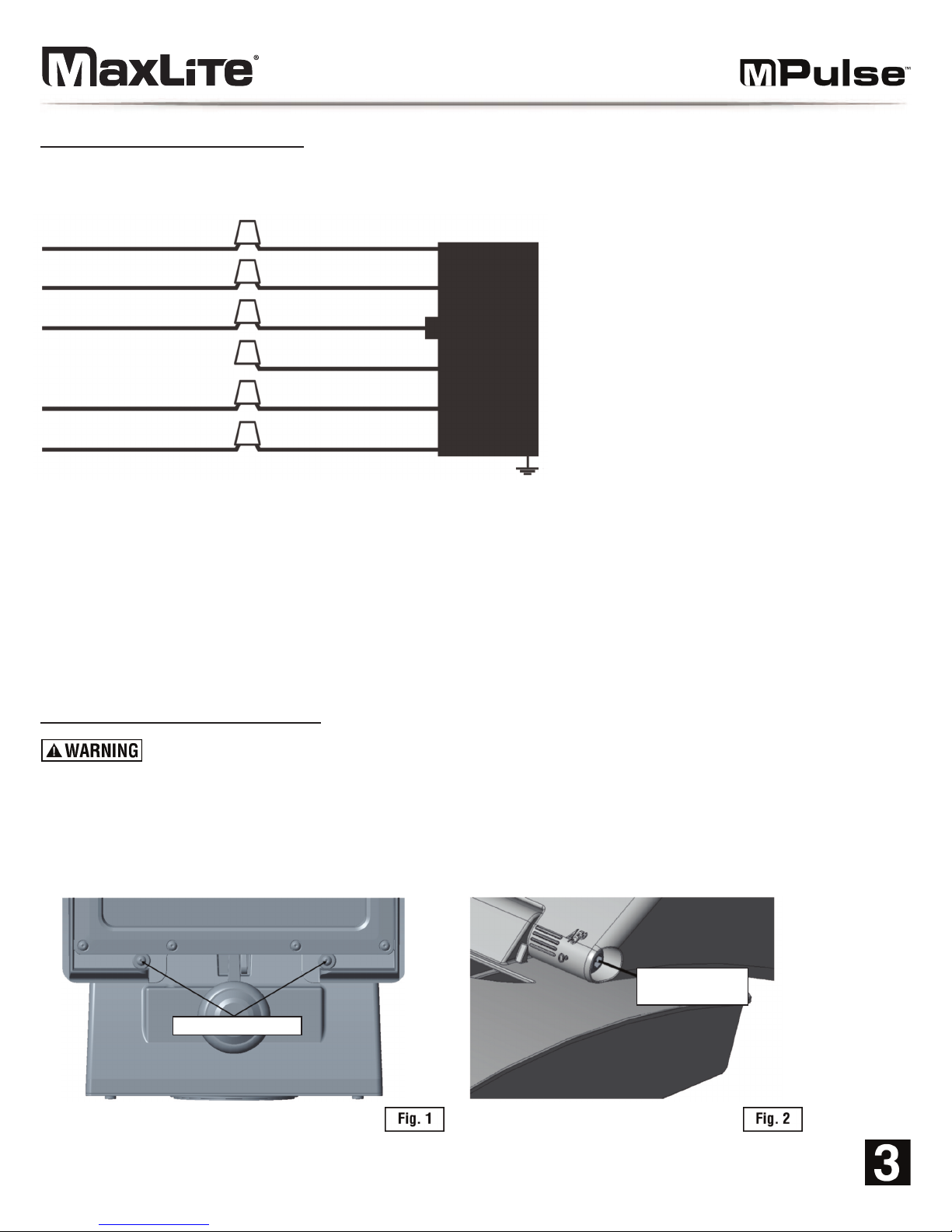
Schéma de câblage général
MISE EN GARDE: Coupez l’alimentation électrique au niveau du fusible ou du boîtier du disjoncteur avant de
brancher l’appareil à l’alimentation électrique.
Installation et fonctionnement
Débranchez l'alimentation en coupant le disjoncteur ou en retirant le fusible approprié sur la boîte à fusibles.
La mise hors tension par l'interrupteur d'éclairage n'est pas suffisante pour éviter les chocs électriques.
1. L'appareil doit être réglé à un angle de coupure de 0 °. Si cet angle est celui désiré, passez à l'étape 5.
Si un autre angle est souhaité (15 °, 30 ° ou 45 °), retirez les deux vis hexagonales avant (Figure 1).
2. 2. Desserrez les vis de réglage (Figure 2) sur le côté du luminaire.
Câblage réglable de 0 à 10V:
1.) Connectez le fil de l’éclairage noir au fil d’alimentation de la PHASE.
2.) Connectez le fil blanc de l’éclairage au fil d’alimentation NEUTRE.
3.) Connectez le fil vert de l’éclairage pour alimenter le fil de la mise à la terre.
4.) Mettre un bouchon au fil JAUNE.
5.) Connectez le fil du luminaire violet au fil DIM (V+).
6.) Connectez le fil gris du luminaire au fil DIM (V-).
PHASE
NEUTRE
TERRE VERT
BLANC
NOIR
Plafonnier
lumineux
JAUNE
(-) RÉGLABLE V- VIOLET
(-) RÉGLABLE V- GRIS
Vis hexagonales avant
Vis de réglage
de tête
© Copyright 2018. MaxLite, Inc. Tous droits réservés.
12 York Ave, West Caldwell, NJ 07006 Tel : 800-555-5629 Télécopie : 973-244-7333 Courriel : [email protected]
Page 20
Installation et fonctionnement (suite)
3. Inclinez la tête à l'angle désiré (15 °, 30 ° ou 45 °). Les trous dans les deux
supports centraux doivent s'aligner en fonction de l'angle que l'on cherche à
obtenir. Verrouillez la tête avec la vis Philips incluse (Figure 3). Il est recommandé
d'utiliser un long tournevis cruciforme (au moins de 8 po de la base) et d'entrer
par le côté du luminaire pour le serrage de la vis.
4. Desserrez les vis de réglage (Figure 2) sur le côté du luminaire.
5. Utilisez un tournevis plat pour retirer les deux bouchons caoutchouc sur les
côtés du boitier de dérivation (Figure 4).
6. Retirez les vis des côtés du boitier de dérivation avec une clé hexagonale M4 (Figure 5).
7. Utilisez un tournevis plat pour dévisser le capuchon à l'arrière de la plaque de montage du boitier de
dérivation (Figure 6).
8. Séparez la plaque de montage arrière du boitier. Un tournevis plat peut être nécessaire pour retirer la plaque de
montage arrière du boitier de dérivation (Figure 7).
9. Percez des trous de montage dans la plaque de montage en suivant le gabarit comme indiqué. Percer à travers les
emplacements de trous surélevés qui correspondent aux points de montage sur la boîte de jonction prévue (Figure 8):
Ø 2.774”
[70.46]
Ø 3.500”
[88.9]
© Copyright 2018. MaxLite, Inc. Tous droits réservés.
12 York Ave, West Caldwell, NJ 07006 Tel : 800-555-5629 Télécopie : 973-244-7333 Courriel : [email protected]
Page 21
Installation et fonctionnement (suite)
10. Fixez la plaque de montage à la boîte de jonction dans le mur avec les vis.
11. Accrochez le boitier de dérivation sur la plaque de montage. Laissez l'appareil pendre
par les crochets pour faciliter le câblage (Figure 9).
12. Tirez les fils par le trou dans la plaque de montage et effectuer les connexions de
câblage en suivant le schéma de câblage (Voir le schéma de câblage à la page 3):
13. Replacez le boitier de dérivation sur la plaque de montage. Assurez-vous que le joint
autour de la plaque de montage est bien en place. Fixez le boîtier de dérivation à la
plaque de montage en utilisant les vis sur les côtés du boitier.
14. Couvrez les vis latérales avec les bouchons en caoutchouc.
© Copyright 2018. MaxLite, Inc. Tous droits réservés.
12 York Ave, West Caldwell, NJ 07006 Tel : 800-555-5629 Télécopie : 973-244-7333 Courriel : [email protected]
Page 22
MaxLite Inc. garantit ses produits pour une période minimale de DIX (10) ans à compter de la date d’achat originale
auprès de MaxLite ou de son distributeur/revendeur agréé (la « Période de garantie ») : Si un produit ne marche pas
pendant la Période de garantie comme conséquence de défauts de matériaux ou de fabrication, MaxLite, à son choix,
le réparera, le remplacera par un produit identique ou un similaire.
Veuillez vous référer au site Web de Maxlite (à http://maxlite.com/resources/warranties) pour les conditions complètes
d’application de notre garantie.
Limitation de responsabilité
LA PRÉSENTE GARANTIE EST EXCLUSIVE ET EST LE SEUL RECOURS POUR TOUTES LES RÉCLAMATIONS,
QU’ELLES SOIENT CONTRACTUELLES, DÉLICTUELLES OU AUTRES PROVENANT DE L’ÉCHEC DU PRODUIT
ET REMPLACE TOUTES LES AUTRES GARANTIES, EXPRESSES OU IMPLICITES, Y COMPRIS TOUTES LES
GARANTIES DE QUALITÉ MARCHANDE OU APTITUDE À UN USAGE PARTICULIER, QUELLES GARANTIES
SONT EXPRESSÉMENT EXCLUES DANS LES LIMITES AUTORISÉES PAR LA LOI ET, DANS TOUS LES CAS,
SONT LIMITÉES À LA PÉRIODE DE GARANTIE STIPULÉE CI-DESSUS. LA RESPONSABILITÉ DE MAXLITE
SERA LIMITÉE AUX TERMES DE LA GARANTIE EXPRESSE ÉNONCÉE ICI. MAXLITE NE PEUT EN AUCUN CAS
ÊTRE TENU RESPONSABLE DES DOMMAGES SPÉCIAUX, FORTUITS OU CONSÉCUTIFS, Y COMPRIS, SANS
LIMITATION, LES DOMMAGES RÉSULTANT DE LA PERTE D’UTILISATION, DES BÉNÉFICES, DE L’ACTIVITÉ OU
DU FONDS COMMERCIAL, DES FRAIS DE MAIN-D’ŒUVRE, DE DÉMÉNAGEMENT OU D’INSTALLATION, DE
DIMINUTION DE LA LAMPE, ET/OU DÉTÉRIORATION DE LA PERFORMANCE DE LA LAMPE, QUE MAXLITE AIT
OU NON ÉTÉ AVISÉE DE LA POSSIBILITÉ DE CECI. LA RESPONSABILITÉ TOTALE DE MAXLITE POUR UN
PRODUIT DÉFECTUEUX NE PEUT EN AUCUN CAS DÉPASSER LE PRIX D’ACHAT DE CE PRODUIT. LES
SERVICES DE GARANTIE FOURNIS EN VERTU DE CES CONDITIONS NE GARANTISSENT PAS LE
FONCTIONNEMENT ININTERROMPU DE PRODUITS; MAXLITE NE SERA PAS TENU RESPONSABLE DES
DOMMAGES CAUSÉS PAR DES RETARDS IMPLIQUANT UN SERVICE DE GARANTIE.
Cette garantie vous donne des droits légaux spécifiques et vous pourriez également avoir d’autres droits légaux qui
pourront varier selon l’état ou la province. Certains pays ou certaines juridictions n’autorisent pas l’exclusion ou la
limitation de responsabilité pour les dommages indirects ou fortuits, de sorte que la limitation ci-dessus peut ne pas
vous être applicable.
Informations sur la garantie
© Copyright 2018. MaxLite, Inc. Tous droits réservés.
12 York Ave, West Caldwell, NJ 07006 Tel : 800-555-5629 Télécopie : 973-244-7333 Courriel : [email protected]
Page 23

© Copyright 2018. MaxLite, Inc. Tous droits réservés.
12 York Ave, West Caldwell, NJ 07006 Tel : 800-555-5629 Télécopie : 973-244-7333 Courriel : [email protected]
Page 24

© Copyright 2018. MaxLite, Inc. Tous droits réservés.
12 York Ave, West Caldwell, NJ 07006 Tel : 800-555-5629 Télécopie : 973-244-7333 Courriel : [email protected]
 Loading...