

MaxLite MLFP14DP4535, MLFP14DP4541, MLFP14DP4550, MLFP24DP6035, MLFP22DP4541 User Manual
...
FLATMAX LED FLAT PANEL: PERFORMANCE SERIES
USER MANUAL
Thank you for purchasing this MaxLite product.
For additional information or assistance
please e-mail info@maxlite.com
or log on to www.maxlite.com
and click on the
Information and Quotes bar.
INSTALLATION GUIDE FOR:
1X4:
MLFP14DP4535
MLFP14DP4541
MLFP14DP4550
2X2:
MLFP22DP4535
MLFP22DP4541
MLFP22DP4550
2X4:
MLFP24DP6035
MLFP24DP6041
MLFP24DP6050

TABLE
OF
DESCRIPTION....... 1
CAPABILITIES........ 1
TECHNICAL SPECIFICATIONS....... 2
FEATURES....... 3-4
MOUNTING PANELS IN CEILING....... 5
SET-UP....... 6
CONNECTING TO AC POWER SOURCE....... 7
SET-UP FOR ON/OFF........ 7
SET-UP FOR OPTIONAL IR REMOTE....... 8
SET-UP FOR 0-10V BALLAST DIMMER
Building Controls / Daylight Harvesting....... 9
SET-UP FOR 0-10V SIMPLE WALL DIMMING....... 10
SET-UP FOR LINKING PANELS....... 11
CONTENTS
DESCRIPTION & CAPABILITIES
DESCRIPTION
Models: Available in 1’x4’, 2’x2’, 2’x4’
Construction: A high performance LED flat panel designed for
installation in drop ceilings; typically used to replace standard 2’x2’
and 2’x4’ fluorescent fixtures. The profile is slim, only 4.1 inches deep
including the junction box, making it ideal for low depth ceiling cavities.
The housing provides maximum heat sink and thermal control. The lens is
a translucent white polycarbonate.
CAPABILITIES
On/Off: Panels can operate independently, or can be daisy
chained together to work with standard on/off wall switches.
Dimming: Panels are fully dimmable with a standard 0-10V wall dimmer,
the hand-held remote dimmer, Building Controls and DaLI.
Building Controls: With the addition of Controls the panels can be
automated and customized to room use.
Daylight Harvesting: Additional sensors (such as Lutron® Graphic Eye)
added to Building Controls enable user to further reduce energy
consumption by taking advantage of natural light entering the room.
Linking: Up to 30 panels can be linked from the master panel.
1
TECHNICAL SPECIFICATIONS
1’ x 4’
Life: 50,000 hour life based on L70 standards
Self-Driven: No additional drivers required
Power: Connect directly to AC power supply 120V through 277V
Contains No Hazardous Material: Mercury and UV Free
# Of LEDs: 144
Wattage: 45W Nominal
Lumens: 3500-3800
CRI: 82
Color Temperature: 3500K, 4100K and 5000K
Weight: 9 lbs.
2’ x 2’
Life: 50,000 hour life based on L70 standards
Self-Driven: No additional drivers required
Power: Connect directly to AC power supply 120V through 277V
Contains No Hazardous Material: Mercury and UV Free
# Of LEDs: 144
Wattage: 45W Nominal
Lumens: 3500-3800
CRI: 82
Color Temperature: 3500K, 4100K and 5000K
Weight: 9 lbs.
2’ x 4’
Life: 50,000 hour life based on L70 standards
Self-Driven: No additional drivers required
Power: Connect directly to AC power supply 120V through 277V
Contains No Hazardous Material: Mercury and UV Free
# Of LEDs: 288
Wattage: 60W Nominal
Lumens: 4900-5200
CRI: 82
Color Temperature: 3500K, 4100K and 5000K
Weight: 18 lbs.
2
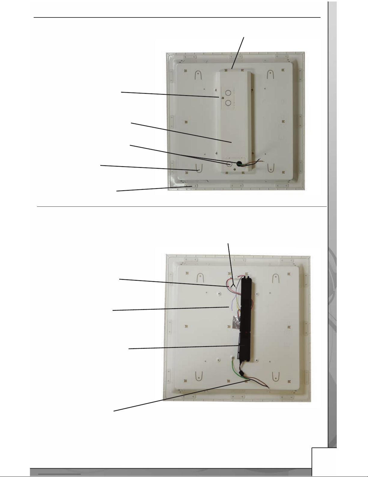
FEATURES
Control Box
Back Panel
Control Box Removed
3
Violet/Yellow/Grey
Option leads
Option Module
Mounting Studs
Black, White, Green
for connection to
AC power source and
ground
Knock Outs
Wire Tie
Off Loops
Pass Thru
Wire Access
Face Frame Clip
IR Option Knock
Out Opening
Red/Blue
LED board
Leads
Power Supply
FEATURES
0-10V Connection on Dimming Control
LED Board Leads
IR Eye
Power Unit
4
Dimming Sensor
0-10V Wire
IR Dimmer
Controller

MOUNTING PANELS IN CEILING
5
Ceiling Grid Groove:
1) The MaxLite LED Flat
Panels are designed to
lay into a gridded ceiling.
Simply start on one side
and gently lay down the
panel.
2) Open seismic hanger
180° to engage ceiling
grid frame.
* Model shown for referance only
* Note: Uniform support is vital; for safety purposes, each panel must have support wire attached.
Safety Wire Hangers:
Safety hanger tabs on the back of the panel
bend up easily to accept wire from the ceiling
structure. Thread wire through the tab and finish
off as for any other suspended or grid fixture.

SET-UPs
ON
POWER
UP
DOWN
MIN
MAX
1. On/Off and AC Power Connection
2. IR Remote
3. 0-10 Ballast/Building Controls (Daylight Harvesting):
4. Simple Wall Dimming
5. Linking Panels: Link up to 30 panels from master using 0-10 wires
6
0-10 Dimmer
0-10 0-10
0-10

CONNECTING TO AC SOURCE
7
Connecting panels to AC source supply:
All units must be individually
connected to the AC supply.
(120-277 VAC)
Black = Line
White = Neutral
Green = Ground
ON/OFF operation:
Line connection to be made to switched
lead from source.
AC supply connections

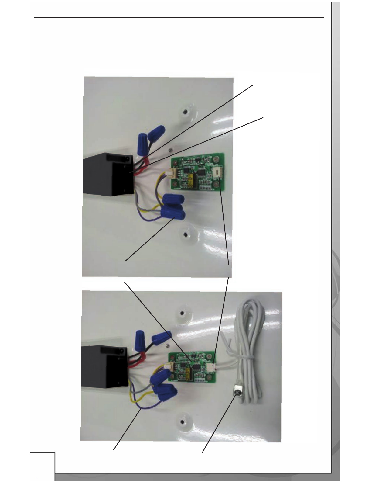
SET UP OPTIONAL I.R. REMOTE
1. Follow Connecting Power procedures (see page 8).
Violet
Yellow
Grey
Power
Supply
IR DIMMER
Module
3. Connect control wires
from dimmer control to
driver violet, yellow, grey
2. Position IR Sensor so it can be visible to the Remote Controller
4. Connect IR Sensor Cable to
Dimmer controller input labeled IR
after cover is re installed.
5. IF IR REMOTE IS TO BE USED IN THE WALL
CRADLE ACCESSORY- The IR sensor must be
positioned in close proximity to the remote
8
IR Sensor
Locate
Sensor In
Room

SET UP 0-10V BALLAST DIMMER–BUILDING CONTROLS
9
1. Follow Connecting Power procedures (see page 8).
++
Grey
Yellow
CENTRAL SYSTEM
CONTROLLER
Output
0-10
DRIVER
Input
0-10
Violet
5. Mount panel, feed line through knockouts,
and operate
4. 0-10 connection as shown
CENTRAL SYSTEM CONTROLLER
2. Locate the leads violet,
yellow, grey
Wire to violet/yellow/grey
leads (As Shown)
to controller
From
Controller

SET UP FOR WALL DIMMING (0-10V SIMPLE DIMMING)
10
1. Follow Connecting Power procedures (see page 8).
Grey
Yellow
WALL
DIMMER
Output
0-10
DRIVER
Input
0-10
Violet
Grey
Violet
5. Mount panel, feed line through knockouts,
and operate
4. Connect wall dimmer (non-relay wires) to Dimming Controller Wires.
0-10 connection
as shown
2. Locate the leads violet,
yellow, grey
with wire nuts
to wall dimmer
From
Dimmer

SET-UP FOR LINKING PANELS
2. Connect by linking to 0-10 input. Violet and grey wires are the
0-10 input wires
4. Continue this for each additional panel up to 30 panels.
11
Grey
Yellow
WALL
DIMMER
Output
0-10
DRIVER
Input
0-10
Violet
Grey
Violet
0-10 Dimmer
0-10 0-10
0-10
WALL
DIMMER
Output
0-10
DRIVER
Grey
Violet
DRIVER
DRIVER
Yellow
Grey
Violet
Grey
Violet
Panel 1 Panel 2 Panel 3
1. Select one of the panels to
be Master Panel.
Master panel will have 0-10 connection
as shown

Lighting Possibilities
For additional information or assistance
please e-mail info@maxlite.com
or log on to www.maxlite.com
and click on the
Information and Quotes bar.
 Loading...