

MaxLite EXC-GW Instructions Manual

INSTALLATION INSTRUCTIONS FOR COMBINATION
EMERGENCY EXIT LIGHT
IMPORTANT SAFEGUARDS:
When using electrical equipment, basic safety precautions should always be followed.
Including the following
1) READ AND FOLLOW ALL SAFETY INSTRUCTIONS
2) Do not use outdoors.
3) Do not mount near gas or electric heater.
4) Use caution when handling batteries. Avoid possible shorting.
5) Equipment should be mounted at heights to prevent tampering by unauthorized
p ersonnel.
6) The use of accessory equipment is not recommended by the manufacturer, this
may cause unsafe conditions.
7) Do not use this equipment for other than the intended use.
8) Save these instructions.
IMPORTANT:
When relamping, only use lamps specified in the exit sign.
Using other lamp types may result in transformer damage or unsafe conditions.
Battery in this unit may not be fully charged.
After electricity is hooked up to unit, let the battery charge up for at least 24 hours.
Then normal operation of this unit should take effect.
Installation Instructions:
Ceiling Mounting
1) leads to A.C. input leads in J-box, fasten J-box bracketto J-
Connect 20 jumper
box. Use Black wire for 120 volt, Red wire for 277 volt, White wire is common.
2) Fasten canopy to J-box bracket.
3) Snap housing to canopy.
4) Connect and trim input leads to socket leads at upper left corner of housing wire
channel.
5) Mount two R emote lamp head at most.
6) Secure face plate to housing. Remove the proper arrow as required.
Back Mounting
1) leads to A.C. input leads in J-box.Use Black wire for 120 volt,
Connect 20 jumper
Red wire for 277 volt, White wire is common.
2) Remove necessary knockouts and fasten back cover to J-box.
3) Snap housing to back cover.
4) Connect and trim input leads to socket leads at upper left corner of housing wire
channel.
5) Mount two R emote lamp head at most.
6) Secure face plate to housing.
"
"
OPERATION
1. During an electrical power failure, the lamps on the unit will automatically come ON for a minimum of 90 minutes.
2. To test this unit, let it charge correctly with AC power supply for a minimum of 24 hours after its first installation and then
depress the “TEST” switch, the emergency lamps will illuminate. When the switch is released, the lamps will turn OFF.
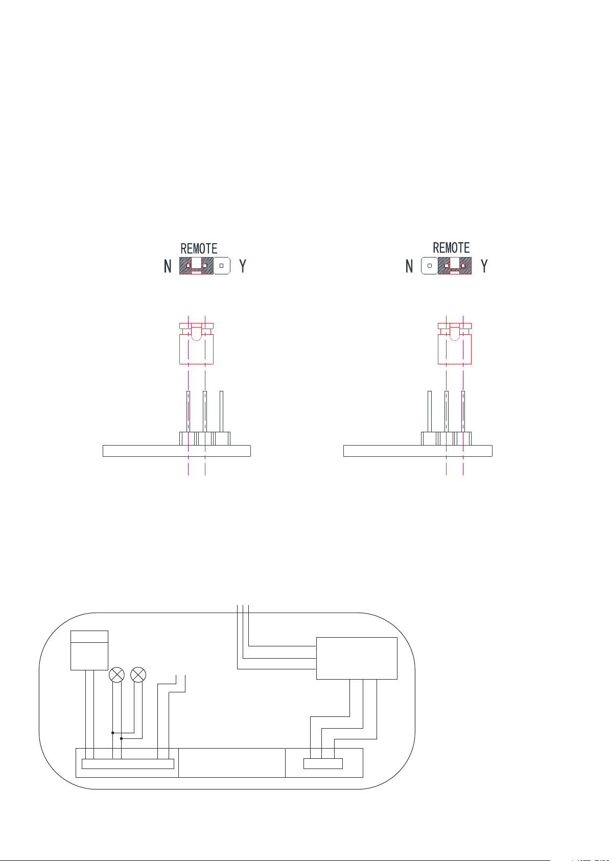
3. For the unit with Self-Diagnostic, must connect as below:
1)When customer doesn’t need remote lamp,please insert teminal to N.(See Figure 1 below)
2) When customer needs remote lamp,please insert teminal to Y.( See Figure 2 below)
Figure 1 Figure 2
LED WIRING DIAGRAM
WARNING:
Unused wires must be capped using enclosed wire nuts.
Wiring diagram
BAT.
3.6 V
180 0mAH
RE M O T E
RE D
RE D
RE D( + )
BL AC K
BL AC K( - )
RE D
BL AC K
BL AC K
LE D B O A R D
RE D 27 7VA C
BL AC K 12 0 VAC
WH IT E CO M
T R S
RE D
BL AC K
RE D
 Loading...