

Page 1
Page : 1
REV: 6/22/2015
Operating Instructions Architectural Downlight Fixtures
MaxLite
®
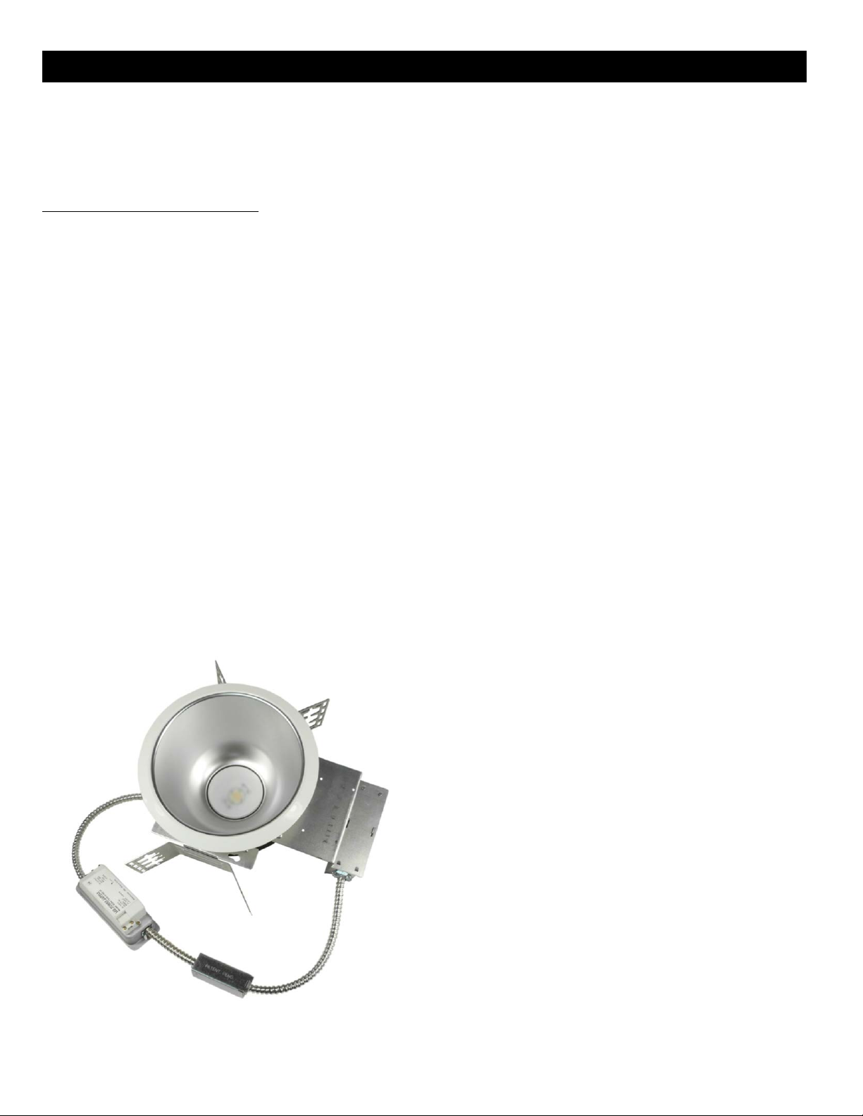
4”, 6”, 8” and 9” LED ARCHITECTURAL DOWNLIGHT
INSTALLATION INSTRUCTIONS
General Safety Information
•
To reduce the risk of death, personal injury or property dam a g e from fire, electric shock, falling parts, cuts/abrasions,
and other hazards read all warnings and instructions included with and on the fixture box and all fixture labels.
•
Before installing, servicing, or performing routine maintenanc e u po n this eq uip m e nt, follow the se ge n era l prec au tion s.
• Commercial installation, service and maintenance of luminaires should be performed by a qualified licensed electrician.
•
For Residential installation: If you are unsure about the installation or m ain ten an ce of the lum in aires , con su lt a qu a lifie
d
licensed electrician and c h eck your local electrical code.
•
DO NOT INSTALL DAMAGED P R O D U C T !
•
This fixture is intended to be connected to a properly installed and g rou nd e d U L listed jun ction bo x.
WARNING:
• Risk of Fire - Supply conductors (power wires) connecting the fixture must be rated minimum 90℃. If uncertain consult an
electrician.
• Ri
sk of fire or electric shock. LED Retrofit Kit installation requires knowledge of luminaires electrical systems.
• Ri
sk of Fire/Electric Shock - If not qualified, do not attempt installation. Co n ta c t a q u a lifie d electrician.
CAUTION:
• For your safety read and understand instructions completely before starting installation.
• To
prevent wiring damage or abrasion, do not expose wiring to edges of sheet metal or other sharp objects.
• Be
fore attempting installation, check your local electrical code, a s it sets the wiring standards fo r your locality.
NOTES:
• If lu
minaire (fixture) is to be switched fr o m a wall switch, make sure black p o wer supply wire is connected to th e
switch. DO NOT connect the white supply wire to the switch.
• Ma
ke certain no bare wires are exposed outside the wire nut connectors.
• Do
not make or alter any open holes in an enclosure of wiring or electrical components during kit installation.
Illustrations on the manua l a r e for ins tallation pu rpo se s on ly. It may no t be iden tical to the fixture pu rch as ed .
Page 2
Page : 2
REV: 6/22/2015
Operating Instructions Architectural Downlight Fixtures
MaxLite
®
4”, 6”, 8” and 9” LED ARCHITECTURAL DOWNLIGHT
INSTALLATION INSTRUCTIONS
INSTALLATION IN NEW CONSTRUCTION
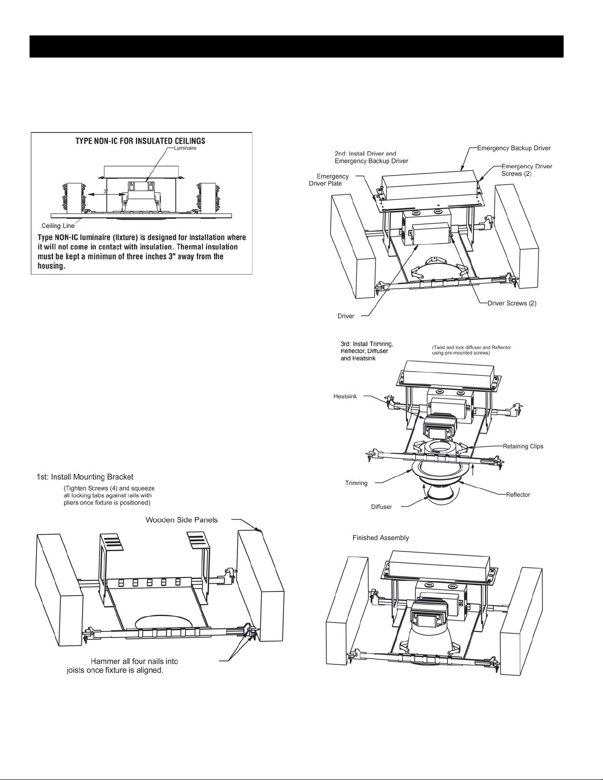
1. Locate center of fixture opening in the ceiling sheetrock and cut a
6-1/2" diameter hole. Note: Cut a 5-1/8" (for 4" fixtures), 8-1/8" (for
8" fixtures) opening.
2. Extend hanger bars to fit between joists. Align the flange of the
hanger bar with the underside of the joists and nail the hanger bar
to the joist (Fig. 2). Level the opposite end of the hanger bar and
nail it securely to the joist. Repeat the process with the other
hanger bar.
3. Position fixture between joists at desired location by sliding
housing on hanger bars. Once the housing is in the desired
location, squeeze tabs into hanger bars to lock luminaire (fixture)
into place (Fig 2).
4
. Follow steps 1 through 5 under Electrical Connections.
Figure 1.
Figure 2.
Figure 3.
Figure 4.
Page 3
Page : 3
REV: 6/22/2015
Operating Instructions Architectural Downlight Fixtures
MaxLite
®
4”, 6”, 8” and 9” LED ARCHITECTURAL DOWNLIGHT
INSTALLATION INSTRUCTIONS
INSTALLATION IN SUSPENDED CEILINGS
1. Locate fixture proposed fixture center in the ceiling tile and cut a
6-1/2" diameter hole. Note: Cut a 5-1/8" (for 4" fixtures), 8-1/8" (for 8"
fixtures) opening.
2. Place ceiling tile in the T-bar grid.
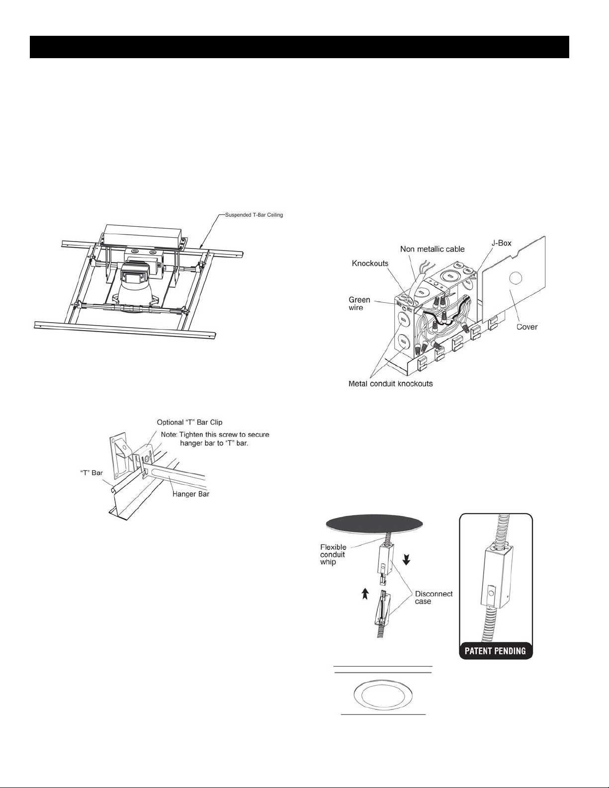
3. Place fixture into position and snap bar hanger foot with integral
T-bar clips onto T-bars (Fig. 6).
4. Secure hanger bars to T-bars and properly support the fixture from
the building structure. Note: Optional T-Bar Clips and screws may be
used as local code authority or site conditions require (Fig. 6).
5. To secure luminaire (fixture) position in ceiling, squeeze tabs into
hanger bars to lock luminaire (fixture) into place on bars.
6. Follow steps 1 through 5 under "Electrical Connection"
ELECTRICAL CONNECTION
1. Provide electrical service according to the "National Electrical Code" or
your local electrical code to the junction box on the fixture frame.
2. Remove appropriate size knockout on fixture J-box for conduit
connector.
3. Remove J-box cover to J-box by pushing up on spring clip. Attach
Conduit with connector to J-box and secure (Fig. 7)
4. Connect supply wires to fixture wires and insulate with proper size wire
nuts (not provided).
a.) Connect incoming ground wire (green or bare) to fixture ground
wire (green or bare).
b.) Connect incoming common (white) wire to fixture common
(white).
c.) Connect incoming hot (typically black) wire to fixture black wire.
5. Replace J-box cover.
INSTALLATION INTO RECESSED HOUSING
1. Plug the female connector of the retrofit-kit onto the male connector of
the flexible conduit whip assembly. (Fig. 8)
2. Connect disconnect case (Patent pending) by snap-on fit.
3. Tuck flexible conduit whip into the housing and carefully push the
retrofit-kit into existing housing. (Fig. 9)
Figure 5.
Figure 6.
Figure 7.
Figure 8.
Figure 9.
 Loading...