

Page 1
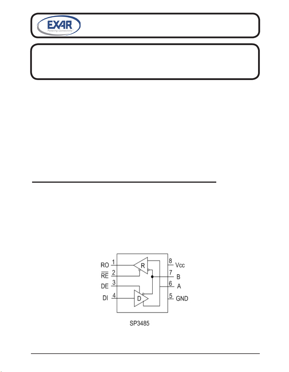
SP3485
+3.3V Low Power Half-Duplex RS-485
Transceiver with 10Mbps Data Rate
• RS-485 and RS-422 Transceiver
• Operates from a single +3.3V Supply
• Interoperable with +5.0V logic
• Driver/Receiver Enable
• -7V to +12V Common-Mode Input Voltage Range
• Allows up to 32 transceivers on the serial bus
• Compatibility with industry standard 75176 pinout
• Driver Output Short-Circuit Protection
DESCRIPTION
The SP3485 device is a +3.3V low power half-duplex transceiver that meets the specications of the RS-485 and RS-422 serial protocols. This device is pin-to-pin compatible with
the Exar SP481, SP483 and SP485 devices as well as popular industry standards. The
SP3485 features the Exar BiCMOS process, allowing low power operation without sacricing
performance. The SP3485 can meet the electrical specications of the RS-485 and RS-422
serial protocols up to 10Mbps under load.
Exar Corporation 48720 Kato Road, Fremont CA, 94538 • 510-668-7017 • www.exar.com SP3485_100_061912
1
Page 2
ABSOLUTE MAXIMUM RATINGS
These are stress ratings only and functional operation
of the device at these ratings or any other above those
indicated in the operation sections of the specications
below is not implied. Exposure to absolute maximum
rating conditions for extended periods of time may
affect reliability.
VCC.....................................................................+6.0V
Input Voltages
Logic....................................-0.3V to +6.0V
Drivers.................................-0.3V to +6.0V
Receivers.........................................+/-15V
Output Voltages
Drivers.............................................+/-15V
Receivers............................-0.3V to +6.0V
Storage Temperature.......................-65˚C to +150˚C
Power Dissipation
8-pin NSOIC...................................................600mW
(derate 6.90mW/ºC above +70ºC)
T
= T
to T
AMB
and VCC = +3.3V +/-5% unless otherwise noted.
MIN
MAX
ELECTRICAL CHARACTERISTICS
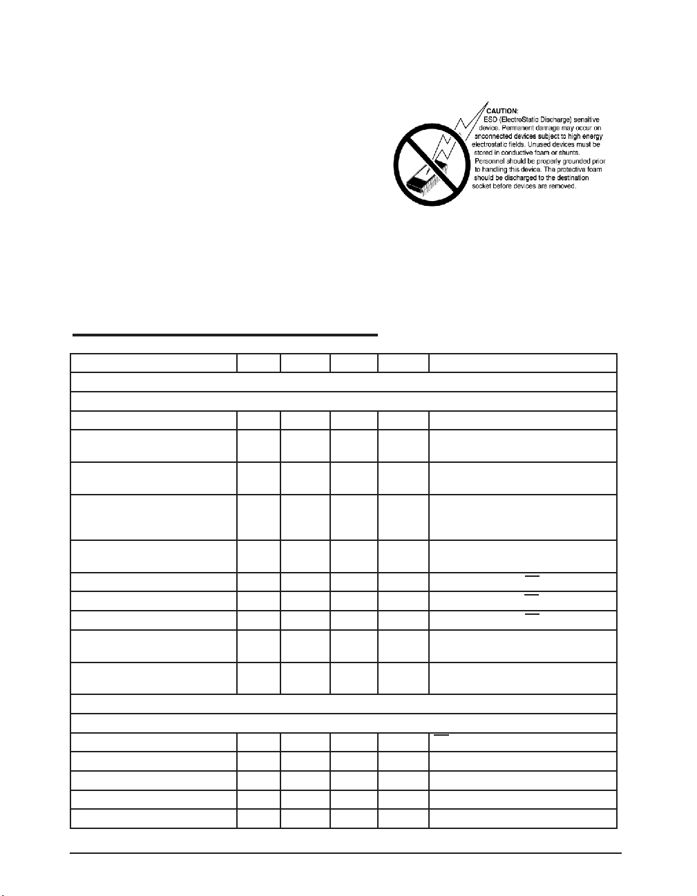
PARAMETERS MIN. TYP. MAX. UNITS CONDITIONS
SP3485 DRIVER
DC Characteristics
Differential Output Voltage GND Vcc Volts Unloaded; R = ∞Ω ; Figure 1
Differential Output Voltage 2 Vcc Volts With Load; R = 50Ω (RS-422);
Figure 1
Differential Output Voltage 1.5 Vcc Volts With Load; R = 27Ω (RS-485);
Figure 1
Change in Magnitude of Driver
0.2 Volts R = 27Ω or R = 50Ω; Figure 1
Differential Output Voltage for
Complimentary states
Driver Common Mode Output
3 Volts R = 27Ω or R = 50Ω; Figure 1
Voltage
Input High Voltage 2.0 Volts Applies to DE, DI, RE
Input Low Voltage 0.8 Volts Applies to DE, DI, RE
Input Current +/-10 µA Applies to DE, DI, RE
Driver Short Circuit Current
V
= HIGH
OUT
Driver Short Circuit Current
V
= LOW
OUT
+/-250 mA -7V ≤ VO ≤ +12V; Figure 8
+/-250 mA -7V ≤ VO ≤ +12V; Figure 8
SP3485 DRIVER
AC Characteristics
Maximum Data Rate 10 Mbps RE = VCC, DE = V
Driver Input to Output, t
Driver Input to Output, t
PLH
PHL
Differential Driver Skew 2 10 ns |t
20 40 60 ns Figures 2 & 9
20 40 60 ns Figures 2 & 9
- t
|, Figures 2 and 10
DO1
DO2
CC
Driver Rise or Fall Time 5 20 ns From 10%-90%; Figures 3 and 10
Exar Corporation 48720 Kato Road, Fremont CA, 94538 • 510-668-7017 • www.exar.com SP3485_100_061912
2
Page 3
T
= T
to T
AMB
and VCC = +3.3V +/-5% unless otherwise noted.
MIN
MAX
ELECTRICAL CHARACTERISTICS
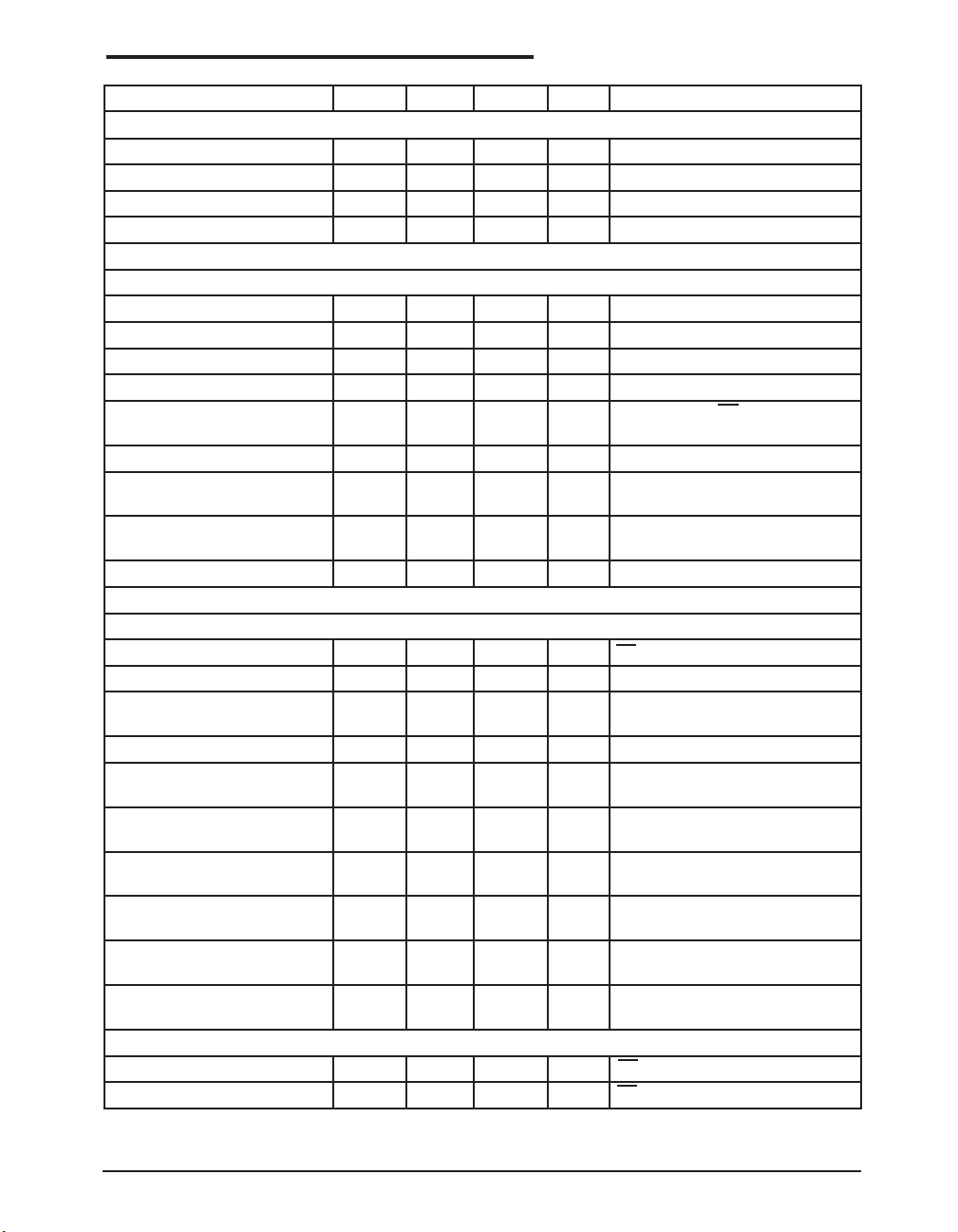
PARAMETERS MIN. TYP. MAX. UNITS CONDITIONS
SP3485 DRIVER AC Characteristics continued
Driver Enable to Output High 52 120 ns Figures 4 and 11
Driver Enable to Output Low 60 120 ns Figures 5 and 11
Driver Disable Time from Low 40 120 ns Figures 5 and 11
Driver Disable Time from High 60 120 ns Figures 4 and 11
SP3485 RECEIVER
DC Characteristics
Differential Input Threshold -0.2 +0.2 Volts -7V ≤ VCM ≤ +12V
Input Hysteresis 20 mV VCM = 0V
Output Voltage HIGH Vcc-0.4 Volts VID = +200mV, -1.5mA
Output Voltage LOW 0.4 Volts VID = -200mV, 2.5mA
Three-State (High Impedance)
Output Current
+/-1 µA 0V ≤ VO ≤ VCC; RE = V
CC
Input Resistance 12 15 kΩ -7V ≤ VCM ≤ +12V
Input Current (A, B); VIN = 12V +1.0 mA DE = 0V, VCC = 0V or 3.6V,
VIN = 12V
Input Current (A, B); VIN = -7V -0.8 mA DE = 0V, VCC = 0V or 3.6V,
VIN = -7V
Short Circuit Current 7 60 mA 0V ≤ VCM ≤ V
CC
SP3485 RECEIVER
AC Characteristics
Maximum Data Rate 10 Mbps RE = 0V, DE = 0V
Receiver Input to Output, t
Receiver Input to Output, t
Receiver Input to Output, t
Receiver Input to Output, t
PLH
PLH
PHL
PHL
Differential Receiver Skew 4 ns t
40 70 100 ns Figures 6 and 12
70 ns T
= +25°C, Vcc = 3.3V,
AMB
Figures 6 and 12
40 70 100 ns Figures 6 and 12
70 ns T
= +25°C, Vcc = 3.3V,
AMB
Figures 6 and 12
= |t
RPHL
- t
RSKEW
Figures 6 and 12
RPLH
|,
Receiver Enable to Output Low 35 60 ns Figures 7 and 13,
S1 closed, S2 open
Receiver Enable to Output High 35 60 ns Figures 7 and 13,
S2 closed, S1 open
Receiver Disable from Low 35 60 ns Figures 7 and 13,
S1 closed, S2 open
Receiver Disable from High 35 60 ns Figures 7 and 13,
S2 closed, S1 open
POWER REQUIREMENTS
Supply Current , No Load 1000 2000 µA RE, DI = 0V or V
; DE = V
CC
CC
Supply Current , No Load 800 1500 µA RE = 0V, DI = 0V or VCC, DE = 0V
Exar Corporation 48720 Kato Road, Fremont CA, 94538 • 510-668-7017 • www.exar.com SP3485_100_061912
3
Page 4
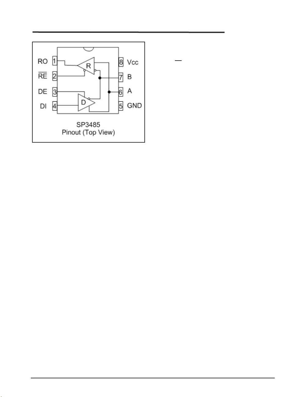
PIN FUNCTION
Pin Function SP3485
Pin 1 - RO - Receiver output
Pin 2 - RE - Receiver Output Enable Active LOW
Pin 3 - DE - Driver Output Enable Active HIGH
Pin 4 - DI - Driver Input
Pin 5 - GND - Ground Connection
Pin 6 - A - Non-Inverting Driver Output/Receiver Input
Pin 7 - B - Inverting Driver Output/Receiver Input
Pin 8 - Vcc - Positive Supply
Exar Corporation 48720 Kato Road, Fremont CA, 94538 • 510-668-7017 • www.exar.com SP3485_100_061912
4
Page 5
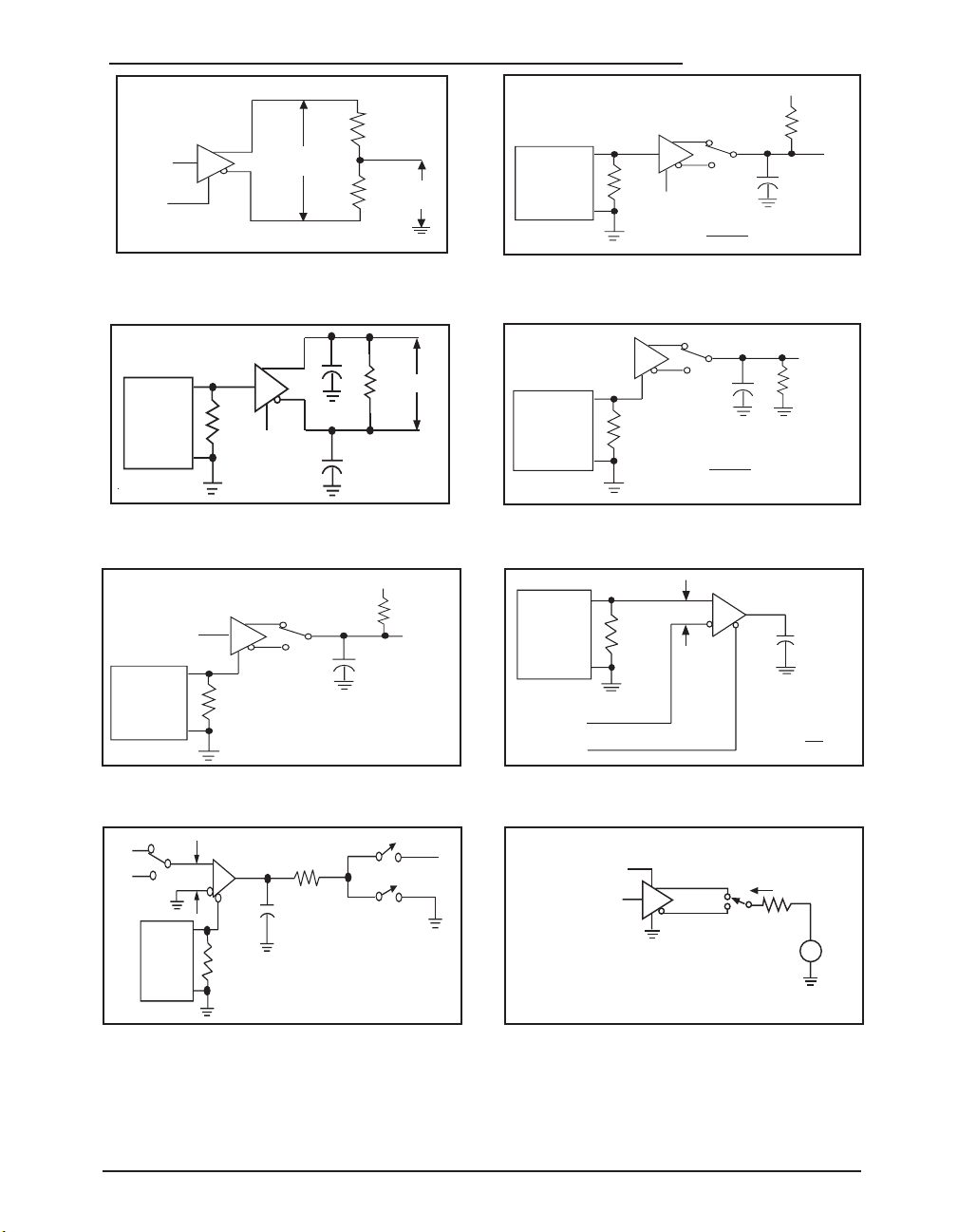
TEST CIRCUITS
R
R
V
OC
D
Vcc
V
OD
GENERATOR
(NOTE 1)
50Ω
C
L
OUT
D
V
CC
RL =
60Ω
CL = 15pF (NOTE 2)
GENERATOR
(NOTE 1)
50Ω
S1
RL = 110Ω
OUT
CL = 50pF
(NOTE 2)
VOM = ≈ 1.5V
VOH + V
OL
2
D
GENERATOR
(NOTE 1)
50Ω
V
CC
S1
V
DM
RL = 27Ω
OUT
CL = 15pF
(NOTE 2)
V
OM
= ≈ 1.5V
VOH + V
OL
2
D
GENERATOR
(NOTE 1)
50Ω
S1
RL = 110Ω
OUT
CL = 50pF
(NOTE 2)
D
0V OR 3V
V
CC
GENERATOR
(NOTE 1)
50Ω
1.5V
0V
V
ID
R
OUT
CL = 15pF
(NOTE 2)
VOM = V
CC
2
1.5V
-1.5V
S3
V
ID
GENERATOR
(NOTE 1)
50Ω
CL = 15pF
(NOTE 2)
R
1k
S1
S2
V
CC
A/Y
D
DI = 0 or Vcc
B/Z
DE = 0 or Vcc
I
OS D
100Ω
-7V to +12V
V
Figure 1. Driver DC Test Load Circuit
Figure 3. Driver Differential Output Delay and
Transition Time Circuit.
Figure 5. Driver Enable and Disable Timing Circuit,
Output Low
Figure 2. Driver Propagation Delay Test Circuit
Figure 4. Driver Enable and Disable Timing Circuit,
Output High
Figure 6. Receiver Propagation Delay Test Circuit
Figure 7. Receiver Enable and Disable Timing
Circuit
NOTE 1: The input pulse is supplied by a generator with the following characteristics:
PRR = 250kHz, 50% duty cycle, tR < 6.0ns, ZO = 50Ω.
NOTE 2: CL includes probe and stray capacitance.
Exar Corporation 48720 Kato Road, Fremont CA, 94538 • 510-668-7017 • www.exar.com SP3485_100_061912
Figure 8. Driver Short Circuit Current Limit Test
5
Page 6
0V
V
OH
t
PLH
t
PHL
V
OM
t
PHL
t
PLH
3V
V
OL
V
OH
1.5V
1.5V
INPUT
Y OUTPUT
V
OM
Z OUTPUT
V
OL
V
OM
V
OM
VOM =
VOH + V
OL
2
≈ 1.5V
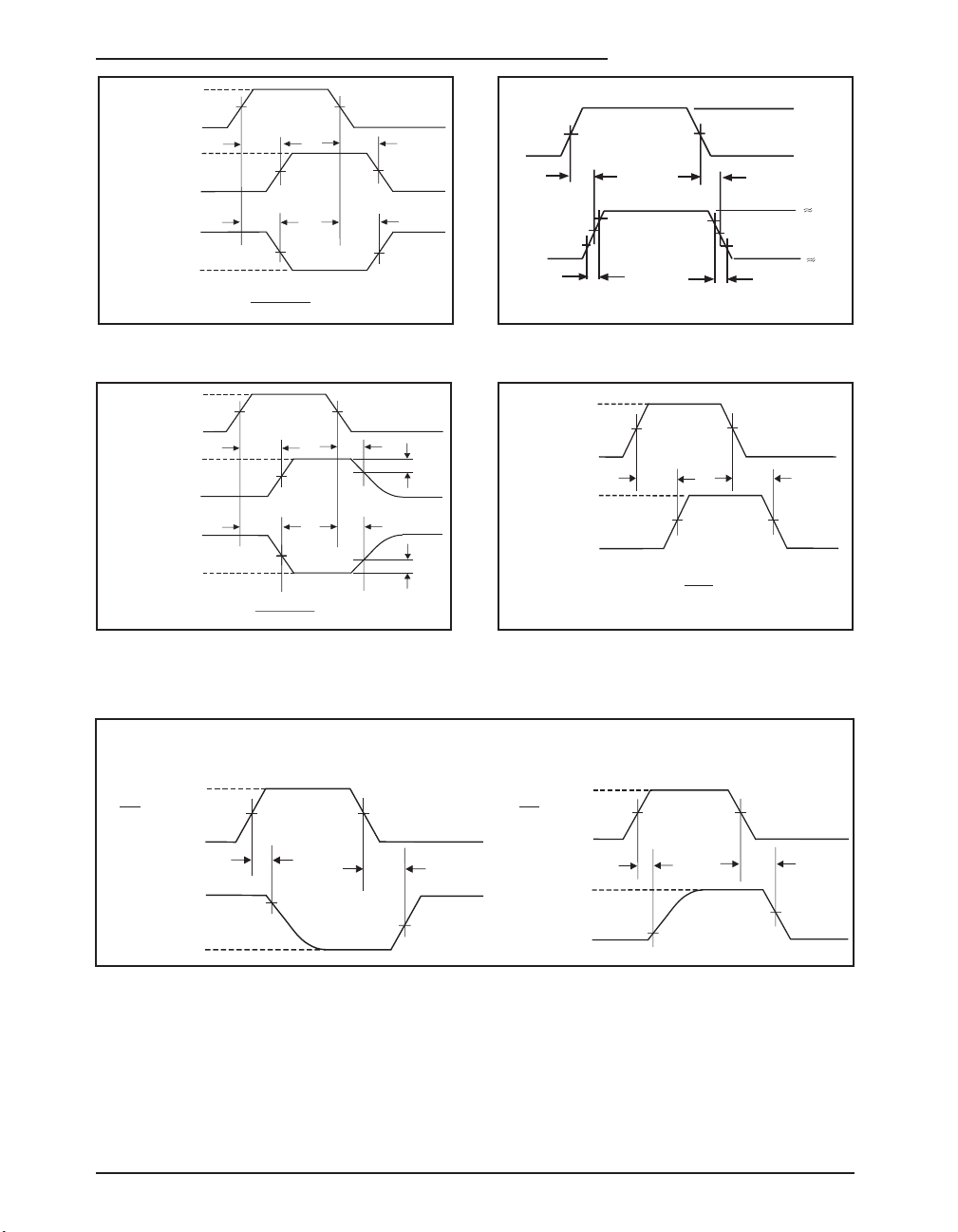
SWITCHING WAVEFORMS
IN
1.5V
t
DO1
1.5V
t
DO2
3V
0V
OUT
50%
50%
10%
10%
90%
90%
t
TD
t
TD
2.0V
-2.0V
0V
VOH
tPZH
0.25V
tPHZ
V
OM
tPZL
tPLZ
3V
VOL
VCC
1.5V
1.5V
DE
OUTPUT
HIGH
V
OM
0.25V
0V
OUTPUT
LOW
VOM =
VOH + V
OL
2
≈ 1.5V
3V
0V
V
CC
t
RPLH
1.5V
t
RPHL
V
OM
V
OM
0V
1.5V
INPUT
OUTPUT
VOM =
V
CC
2
3V
0V
t
PRHZ
1.5V
t
PRZH
t
PRSH
1.5V
1.5V
10%
0V
V
OH
RE
OUTPUT
S1 is open
S2 is closed
S3 = 1.5V
3V
0V
t
PRLZ
1.5V
t
PRZL
t
PRSL
1.5V
1.5V
10%
V
CC
RE
OUTPUT
S1 is closed
S2 is open
S3 = -1.5V
V
OL
Figure 9. Driver Propagation Delay Waveforms
Waveforms
Figure 10. Driver Differential Output Delay and
Transition Time Waveforms
Figure 12. Receiver Propagation Delay WaveformsFigure 11. Driver Enable and Disable Timing
Figure 13. Receiver Enable and Disable Waveforms
Exar Corporation 48720 Kato Road, Fremont CA, 94538 • 510-668-7017 • www.exar.com SP3485_100_061912
6
Page 7
DESCRIPTION
The SP3485 is a member in the family of
+3.3V low power half-duplex transceivers
that meet the electrical specications of the
RS-485 and RS-422 serial protocols. This
device is pin-to-pin compatible with the Exar
SP481, SP483 and SP485 devices as well
as popular industry standards. The SP3485
feature Exar's BiCMOS process allowing
low power operation without sacricing
performance.
Driver
The driver outputs of the SP3485 are differential outputs meeting the RS-485 and
RS-422 standards. The typical voltage
output swing with no load will be 0 volts to
+3.3 Volts. With a load of 54Ω across the
differential outputs, the drivers can maintain
greater than 1.5V voltage levels.
The driver of the SP3485 has a driver enable
control line which is active HIGH. A logic
HIGH on DE (pin 3) will enable the differential
driver outputs. A logic LOW on the DE (pin
3) will tri-state the driver outputs.
The driver of the SP3485 operates up to
10Mbps. The 250mA ISC maximum limit
on the driver output allows the SP3485 to
withstand an innite short circuit over the
-7.0V to +12V common mode range without
catastrophic damage to the IC.
Receiver
The SP3485 receiver has differential inputs
with an input sensitivity of ±200mV. Input
impedance of the receiver is typically 15kΩ
(12kΩ minimum). A wide common mode
range of -7V to +12V allows for large ground
potential differences between systems. The
receiver is equipped with a fail-safe feature
that guarantees the receiver output will be
in a HIGH state when the input is left unconnected. The receiver of the SP3485 operates
up to 10Mbps.
The receiver of the SP3485 has an enable
control line which is active LOW. A logic
LOW on RE (pin 2) will enable the differential
receiver. A logic HIGH on RE (pin 2) of the
SP3485 will disable the receiver.
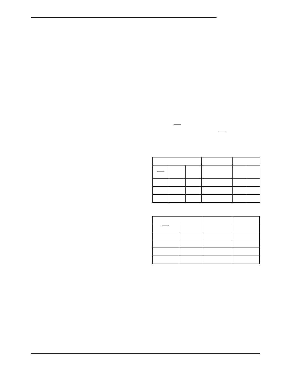
INPUTS OUTPUTS
RE DE DI
X 1 1 No Fault 0 1
X 1 0 No Fault 1 0
X 0 X X Z Z
Table 1. Transmit Function Truth Table
INPUTS OUTPUTS
RE DE A - B R
0 0 +0.2V 1
0 0 -0.2V 0
0 0 Inputs Open 1
1 0 X Z
Table 2. Receive Function Truth Table
LINE
CONDITION B A
Exar Corporation 48720 Kato Road, Fremont CA, 94538 • 510-668-7017 • www.exar.com SP3485_100_061912
7
Page 8
Exar Corporation 48720 Kato Road, Fremont CA, 94538 • 510-668-7017 • www.exar.com SP3485_100_061912
8
Page 9
Model Temperature Range Package Types
SP3485CN-L ....................................................................... 0°C to +70°C ................................................................................................8-pin NSOIC
SP3485CN-L/TR .................................................................0°C to +70°C ................................................................................................8-pin NSOIC
SP3485EN-L...................................................................... -40°C to +85°C..............................................................................................8-pin NSOIC
SP3485EN-L/TR................................................................ -40°C to +85°C..............................................................................................8-pin NSOIC
Note: /TR = Tape and Reel
REVISION HISTORY
DATE REVISION DESCRIPTION
10/15/02 -- Legacy Sipex Datasheet
ORDERING INFORMATION
06/19/12 1.0.0 Convert to Exar Format. Update ordering information and add new Figure 8 - Driver
Short Circuit Current Limit Test Circuit. Remove EOL device SP3481.
Notice
EXAR Corporation reserves the right to make changes to any products contained in this publication in order to improve design, performance or reliability. EXAR Corporation assumes no representation that the circuits are free of patent infringement. Charts and schedules contained herein are only for
illustration purposes and may vary depending upon a user's specic application. While the information in this publication has been carefully checked;
no responsibility, however, is assumed for inaccuracies.
EXAR Corporation does not recommend the use of any of its products in life support applications where the failure or malfunction of the product can
reasonably be expected to cause failure of the life support system or to signicantly affect its safety or effectiveness. Products are not authorized for
use in such applications unless EXAR Corporation receives, in writing, assurances to its satisfaction that: (a) the risk of injury or damage has been
minimized ; (b) the user assumes all such risks; (c) potential liability of EXAR Corporation is adequately protected under the circumstances.
Copyright 2012 EXAR Corporation
Datasheet June 2012
For technical support please email Exar's Serial Technical Support group at: [email protected]
Reproduction, in part or whole, without the prior written consent of EXAR Corporation is prohibited.
Exar Corporation 48720 Kato Road, Fremont CA, 94538 • 510-668-7017 • www.exar.com SP3485_100_061912
9
 Loading...