

Page 1
Enhanced RS-232 Line Drivers/Receivers
FEATURES
• Operates from a Single +5V Power Supply
• Meets all RS-232F and ITU V.28 Specications
• Operates with 0.1μF Ceramic Capacitors
• High Data rate - 120kbps under load
• Low power CMOS Operation
• +/-2kV Human Body Model ESD Protection
• Lead Free packaging available
SP232A
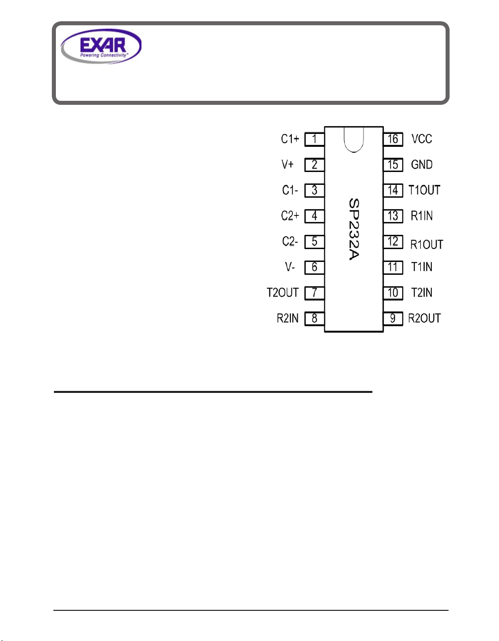
The SP232A is a line driver and receiver pair that meets the specications of RS-232 and V.28 serial
protocols. This device is pin-to-pin compatible with popular industry standard pinouts. The SP232A
offers 120kbps data rate under load, small ceramic type 0.1μF charge pump capacitors and overall
ruggedness for comercial applications. The SP232A features Exar's BiCMOS design allowing for low
power operation without sacricing performance. This device is avaialble in plastic DIP, SOICW and
nSOIC packages operating over the commercial and industrial temperature ranges.
Exar Corporation 48720 Kato Road, Fremont CA, 94538 • (510)668-7000 • Fax (510)668-7017 • www.exar.com SP232A_100_051308
1
DESCRIPTION
Page 2
These are stress ratings only and functional operation of the device at these ratings or any other above
those indicated in the operation sections of the speci-
cations below are not implied. Exposure to absolute
maximum ratings conditions for extended periods of
time may affect reliability.
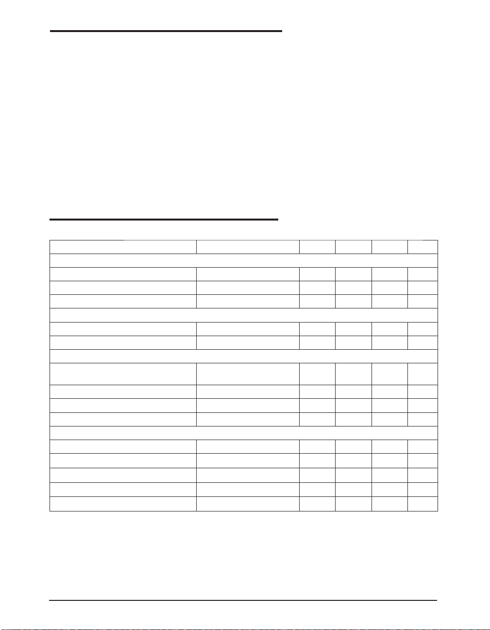
Supply Voltage (VCC)...............................................+ 6V
V+........................................................................... (Vcc-0.3V) to +11.0V
V- .............................................................................-11.0V
Input Voltages
Tin.....................................................-0.3V to (Vcc + 0.3V)
Rin............................................................................+/-15V
Output Voltages
Tout...............................................(V+, +0.3V) to (V-, -0.3V
Rout...................................................-0.3V to (Vcc + 0.3V)
AbSoLUTE MAxiMUM RATingS
Short Circuit duration
Tout.....................................................Continuous
Package Power Dissipation:
Plastic DIP...............................................375mW
(derate 7mW/°C above +70°C)
Small Outline...........................................375mW
(derate 7mW/°C above +70°C)
Storage Temperature..................-65°C to +150°C
Lead Temperature (soldering, 10s).......... +300°C
Vcc=5V ±10%, 0.1μF charge pump capacitors, Tmin to Tmax, unless otherwise noted, Typical values are Vcc=5V
ELECTRiCAL CHARACTERiSTiCS
and Ta=25°C
PARAMETER TEST ConDiTionS Min TYP MAx UniT
TTL inPUT
Logic Threshold LOW Tin 0.8 Volts
Logic Threshold HIGH
Logic Pull-Up Current
TTL oUTPUT
Output Voltge LOW iouT = 3.2 mA: Vcc = +5V 0.4 Volts
Output Voltage HIGH
RS-232 oUTPUT
output Voltage Swing
Output Resistance Vcc = 0V, Vout = +/-2V 300 Ohms
Output Short Circuit Current Innite Duration
Maximum Data Rate CL = 2500pF, RL = 3kΩ
RS-232 inPUT
Voltage Range -15 +15 Volts
Voltage Threshold LOW
Voltage Threshold HIGH
Hysteresis
Resistance
Tin 2.0 Volts
Tin = 0V 15 200 μA
iouT = -1.0 mA 3.5 Volts
all Transmitter outputs loaded
with 3k ohms to GND
Vcc = 5V,
Vcc = 5V,
Vcc = 5V,
Ta=25°C
Ta=25°C
Ta=25°C
Ta=25°C, -15V ≤ Vin ≤ +15V
+/-5.0 +/-6.5V Volts
+/-18 mA
120 240 kbps
0.8 1.2 Volts
1.7 2.4 Volts
0.2 0.5 1.0 Volts
3 5 7 kΩ
Exar Corporation 48720 Kato Road, Fremont CA, 94538 • (510)668-7000 • Fax (510)668-7017 • www.exar.com SP232A_100_051308
2
Page 3
Vcc=5V ±10%, 0.1μF charge pump capacitors, Tmin to Tmax, unless otherwise noted, Typical values are Vcc=5V
and Ta=25°C
DYnAMiC CHARACTERiSTiCS
Driver Propagation Delay TTL to RS_232; CL = 50pF 1.5 3.0 μs
Receiver Propagation Delay RS-232 to TTL,
Instantaneous Slew Rate CL = 10pF, RL = 3-7kΩ 30 V/ μs
Transition Region Slew Rate
PoWER REQUiREMEnTS
Vcc Power Supply Current No Load, Vcc = 5V, Ta=25°C 1.5 5 mA
Vcc Power Supply Current, Loaded
CL = 2500pF, RL = 3kΩ;
Measured from +3V to -3V or
-3V to +3V
All Transmitters RL = 3kΩ,
a=25°C
T
0.1 1.0 μs
10 V/ μs
11 mA
Pin ASSignMEnTS
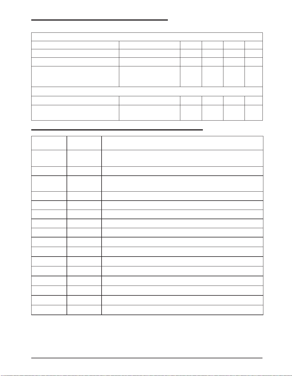
Pin number Pin name Pin Function
ELECTRiCAL CHARACTERiSTiCS
1 C1+
2 V+
3
C1-
4 C2+
5 C26 V-
7 T2OUT
8 R2IN
9 R2OUT
10 T2IN
11 T1IN
12 R1OUT
13 R1IN
14 T1OUT
15 GND
16 Vcc
Positive terminal of the voltage doubler charge pump
capacitor
+6.5V generated by the charge pump
Negative terminal of the voltage doubler charge pump
capacitor
Positive terminal of the inverting charge pump capacitor
Negative terminal of the inverting charge pump capacitor
-6.7V generated by the charge pump
RS-232 driver output
RS-232 receiver input
TTL/CMOS receiver output
TTL/CMOS driver input
TTL/CMOS driver input
TTL/CMOS receiver output
RS-232 receiver input
RS-232 driver output
Ground
5V supply voltage
Exar Corporation 48720 Kato Road, Fremont CA, 94538 • (510)668-7000 • Fax (510)668-7017 • www.exar.com SP232A_100_051308
3
Page 4

DETAiLED DESCRiPTion
The SP232A transceiver is a two driver and two
receiver device that meets the EIA/TIA- 232 and
V.28 serial communication protocol. The device
is pin-to-pin compatible with popular industry
standard pinouts. The SP232A offers 120kbps
data rate, 10V/μs slew rate and a regulated
charge pump that operates from a single 5V
supply. The proprietary on-board charge pump
generates a regulated output of +/-6.5V for RS232 compliant voltage levels.
Theory of operation
The SP232A is made up of three basic circuit
blocks: 1. Driver, 2. Receiver, and 3. charge
pump.
Drivers
The drivers are inverting level transmitters that
convert TTL or CMOS logic levels to EIA/TIA232 levels with an inverted sense relative to the
input logic levels. Typically, the RS-232 output
voltage swing is +/-6.5V with no load and +/-
5.0V minimum when fully loaded. The driver out-
puts are protected against innite short-circuits
to ground without degradation in reliability.
The drivers can guarantee output data rates of
120Kbps under worst case loading of 3k ohms
and 2500pF.
The driver output Slew Rate is internally limited
to 30V/μs in order to meet the EIA standards
(EIA-232F). Additionally, the driver output LOW
to HIGH transition meet the monotonicity output
requirements of the standard.
Receivers
The receivers convert EIA/TIA-232 signal levels
to TTL or CMOS logic output levels. Since the
input is usually from a transmission line, where
long cable length and system interference can
degrade the signal, the receiver inputs have a
typical hysteresis margin of 500mV. This ensures that the receiver is virtually immune to
noisy transmission lines. Should a input be left
unconnected, an internal 5Kohm pull-down resistor to ground will commit the output of the receiver to a logic HIGH state. The input voltage
range for the SP232A Receiver is +/-15V.
DESCRiPTion
Charge pump
The charge pump is a patented design and
uses a unique approach compared to older less
efcient designs. The charge pump requires 4
external capacitors and uses a four phase voltage shifting technique. The internal power supply consists of a regulated dual charge pump
that provides output voltages of +/-6.5V. This
is important to maintain compliant RS-232 lev-
els regardless of power supply uctuations.
The charge pump operates in a discontinous
mode using an internal oscillator. If the voltages
are less than a magnitude of 6.5V, the charge
pump is enabled. If the output voltage exceed
a magnitude of 6.5V then the charge pump is
disabled. The internal oscillator controls the four
phases of the voltage shifting. A description of
each phase follows:
Phase 1
Vss charge store and double: The positive terminals of capacitors C1 and C2 are charged
from Vcc with their negative terminals initially
connected to ground. C1+ is then connected
to ground and the stored charge from C1- is
superimposed onto C2-. Since C2+ is still connected to Vcc the voltage potential across C2 is
now 2 x Vcc.
Phase 2
Vss transfer and invert: Phase two connects
the negative terminal of C2 to the Vss storage
capacitor and the positive terminal of C2 to
ground. This transfers the doubled and inverted
(V-) voltage onto C4. Meanwhile, capacitor C1
is charged from Vcc in order to prepare it for its
next phase.
Phase 3
Vdd charge store and double: Phase three is
identical to the rst phase. The positive terminals of C1 and C2 are charged from Vcc with
their negative terminals initially connected to
ground. C1+ is then connected to ground and
the stored charge from C1- is superimposed
onto C2-. Since C2+ is still connected to Vcc
the voltage potential across capacitor C2 is now
2 x Vcc.
Exar Corporation 48720 Kato Road, Fremont CA, 94538 • (510)668-7000 • Fax (510)668-7017 • www.exar.com SP232A_100_051308
4
Page 5
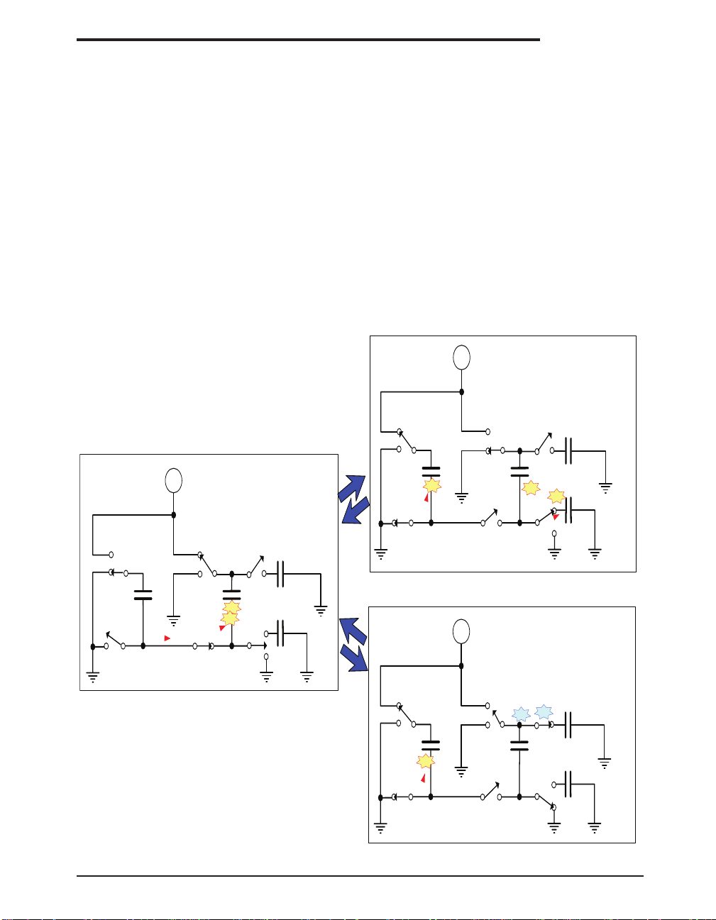
Phase 4
C
2
+
-
V
CC
C
3
C
4
C
1
+
+
+
e
-
e
-
Phases 1 and 3: Store/Double.
Double charge from C 1 onto C2.
C 2 is now charged to -2xVcc
+
C
2
+
-
V
CC
C
3
C
4
C
1
+
+
+
e
-
+
e
+
e
+
C
2
+
-
V
CC
C
3
C
4
C
1
+
+
+
Phase 2 – Vss transfer from C2 to C4.
Meanwhile C 1 is charged to Vcc
e
-
e
-
e
-
+
Vss
transfer from C2 to C3.
Meanwhile C1 is charged to Vcc
V
DD
V-
V+
V-
V+
V+
Patented 5,306,954
Phase 4 V
DD
Vdd transfer. The fourth phase connects the
negative terminal of C2 to ground and the positive terminal of C2 to the Vdd storage capacitor .
This transfers the doubled (V+) voltage onto C3.
Meanwhile, capacitor C1 is charged from Vcc to
prepare it for its next phase.
Under lightly loaded conditions, the intelligent
pump oscillator maximizes efciency by running
only as needed to maintain V+ and V- voltage
levels. Since interface transceivers spend most
of their time at idle, this power-efcient innovation can greatly reduce total power consumption. This improvement is made possible by
the independent phase sequences of the Exar
charge pump design.
DESCRiPTion
The clock rate of the charge pump typically operates greater than 70kHz allowing the pump to
operate efciently with small 0.1uF capacitors.
Efcient operation depends on rapid charging
and discharging of C1 and C2. Therefore, the
capacitors should be mounted as close as possible to the IC and have a low ESR (equivalent
series resistance). Inexpensive, surface mount
ceramic capacitors are ideal for use on charge
pump. If polarized capacitors are used the positive and negative terminals should be connected as shown on the typical operating circuit. A
diagram of the 4 individual phases is shown in
Figure 1.
Figure 1. Charge pump phases
Exar Corporation 48720 Kato Road, Fremont CA, 94538 • (510)668-7000 • Fax (510)668-7017 • www.exar.com SP232A_100_051308
5
Page 6
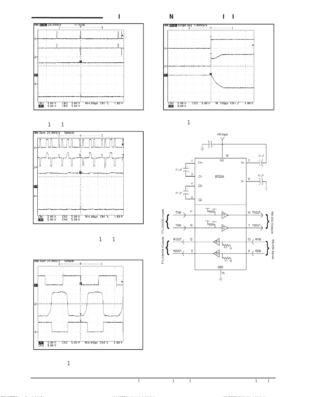
Exar Corporation 48720 Kato Road, Fremont CA, 94538 • (5
0)668-7000 • Fax (5
0)668-70
7 • www.exar.com SP232A_
00_05
3 0 8
6
TYP
= C
= C
= TXin, 2 = TXout/RXin, 3 =
= Vcc, 2 = V+, 3 = V-).
Page 7
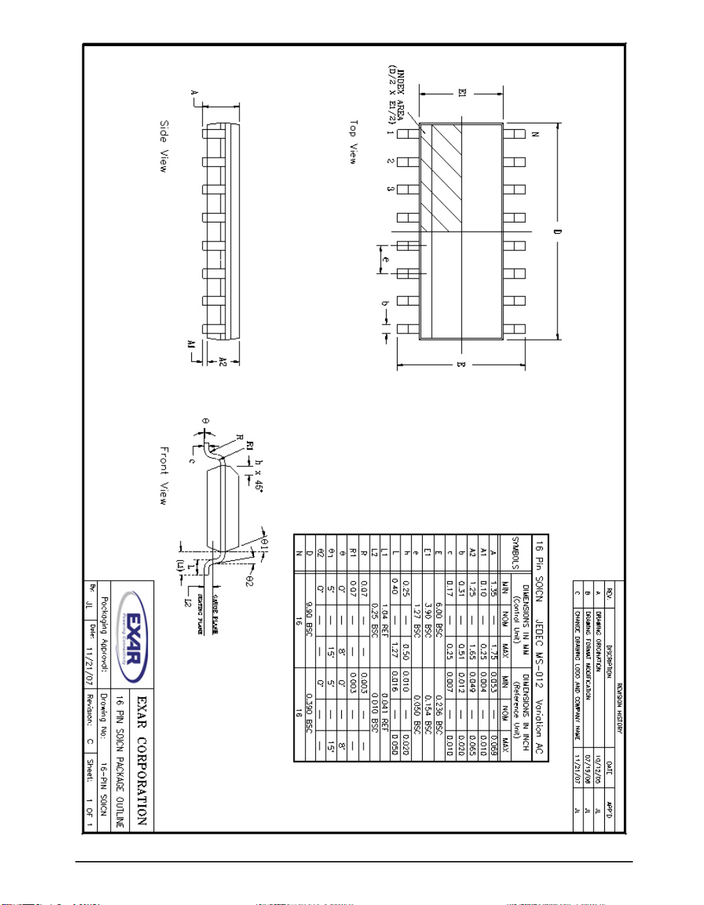
Exar Corporation 48720 Kato Road, Fremont CA, 94538 • (510)668-7000 • Fax (510)668-7017 • www.exar.com SP232A_100_051308
7
Page 8
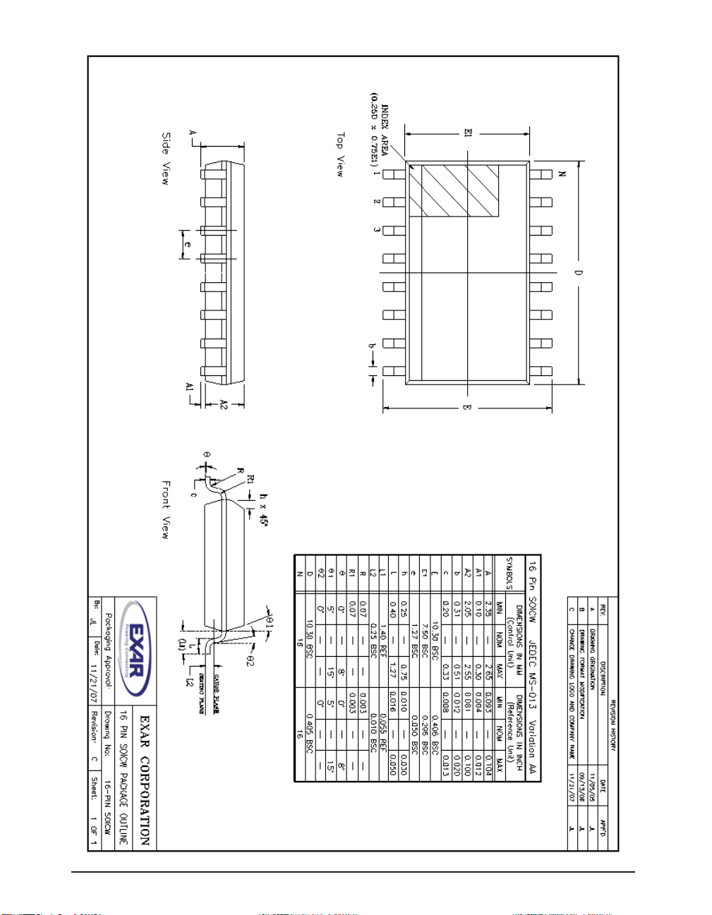
Exar Corporation 48720 Kato Road, Fremont CA, 94538 • (510)668-7000 • Fax (510)668-7017 • www.exar.com SP232A_100_051308
8
Page 9
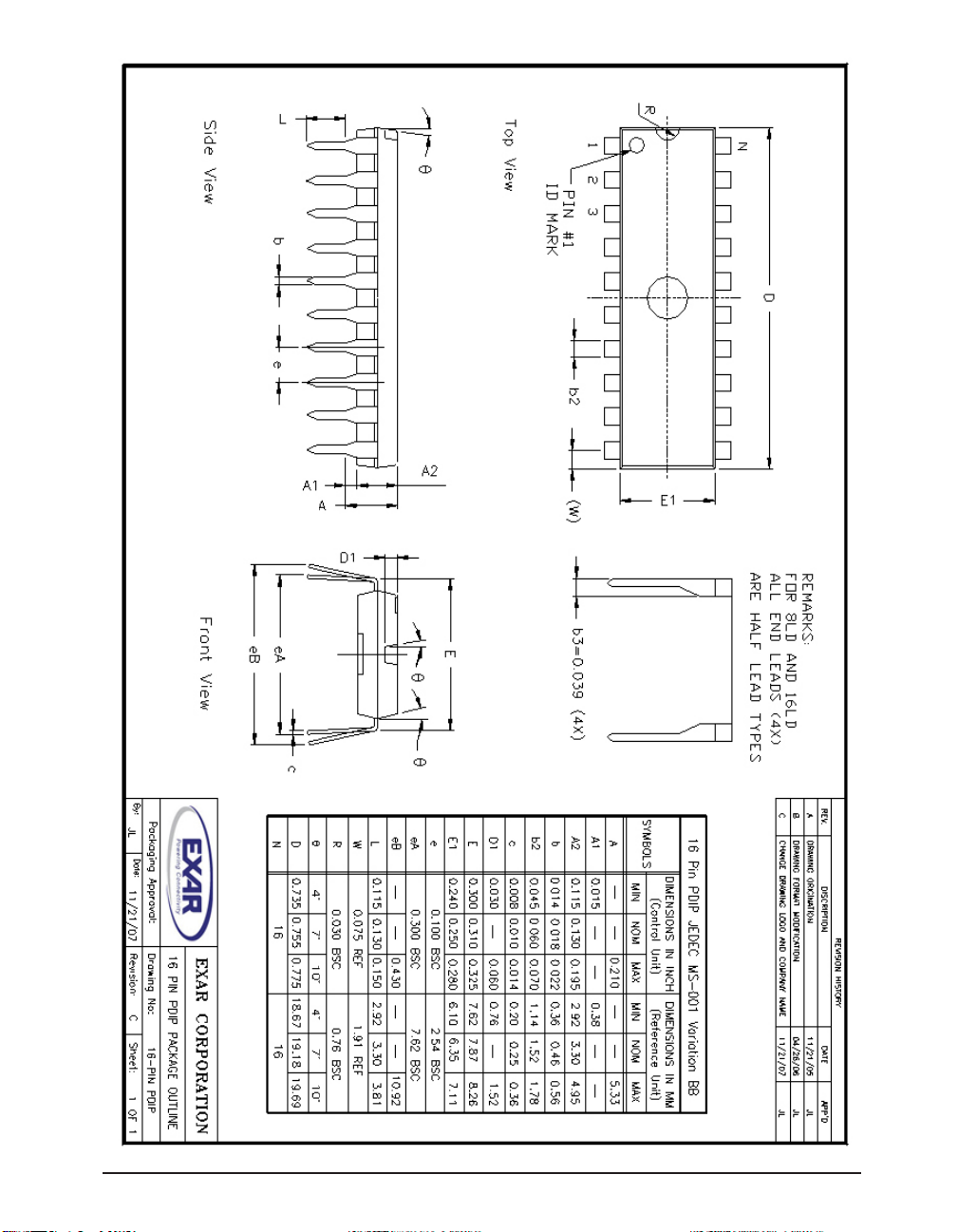
Exar Corporation 48720 Kato Road, Fremont CA, 94538 • (510)668-7000 • Fax (510)668-7017 • www.exar.com SP232A_100_051308
9
Page 10
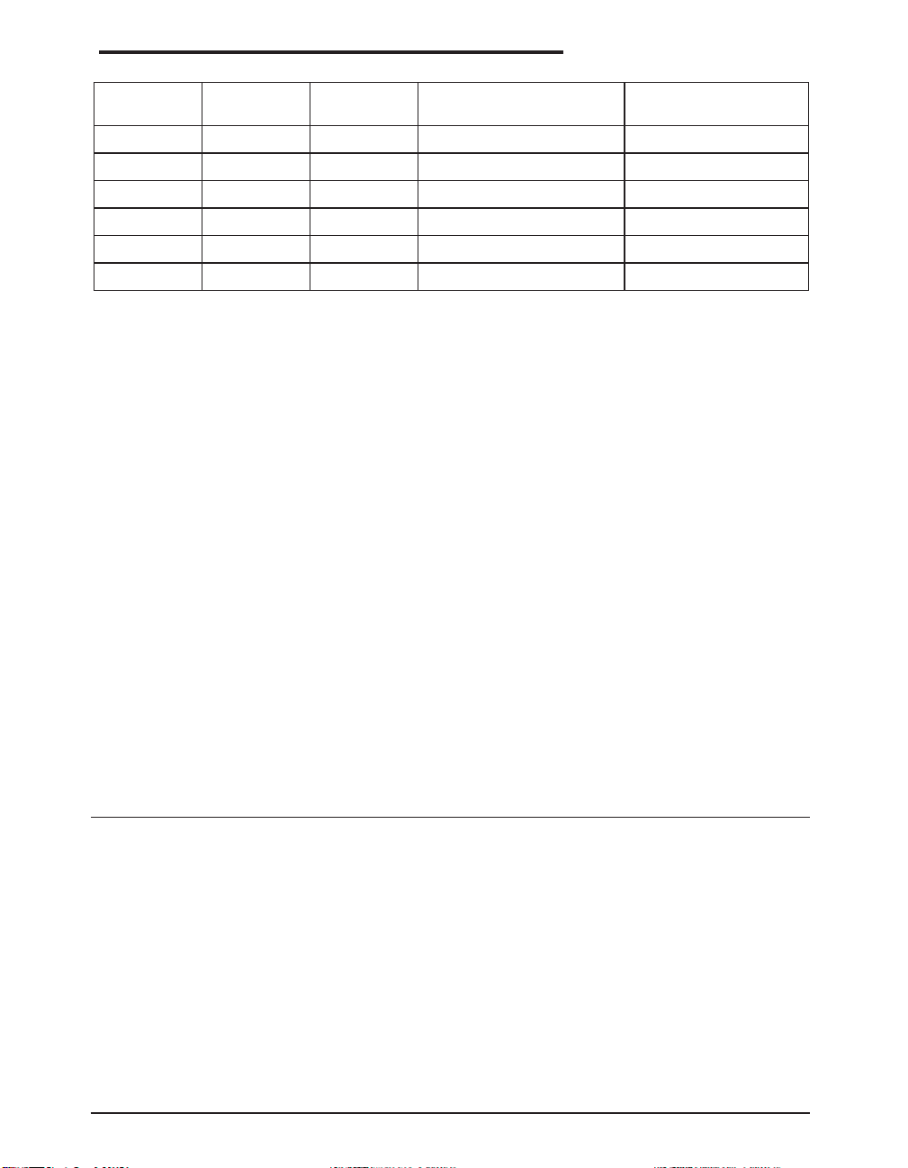
ORDERING INFORMATION
Part number LEAD FREE Tape & Reel Temperature range Package Type
SP232ACN -L /TR From 0 to +70
0
C 16 pin nSOIC
SP232ACT -L /TR From 0 to +700C 16 pin WSOIC
SP232ACP -L /TR From 0 to +70
0
C 16 pin PDIP
SP232AEN -L /TR From -40 to +850C 16 pin nSOIC
SP232AET -L /TR From -40 to +850C 16 pin WSOIC
SP232AEP -L /TR From -40 to +85
All packages are available as lead free (RoHS compliant). To order add “-L” sufx to part number.
For Tape and Reel add “/TR”. Reel quantity is 2,500 for NSOIC.
Example: SP232ACN-L/TR = lead free and Tape and Reel. SP232ACN/TR = standard with Tape
and Reel.
0
C 16 pin PDIP
Notice
EXAR Corporation reserves the right to make changes to any products contained in this publication in order to improve design, performance or reliabil-
ity. EXAR Corporation assumes no representation that the circuits are free of patent infringement. Charts and schedules contained herein are only for
illustration purposes and may vary depending upon a user's specic application. While the information in this publication has been carefully checked;
no responsibility, however, is assumed for inaccuracies.
EXAR Corporation does not recommend the use of any of its products in life support applications where the failure or malfunction of the product can
reasonably be expected to cause failure of the life support system or to signicantly affect its safety or ef
use in such applications unless EXAR Corporation receives, in writting, assurances to its satisfaction that: (a) the risk of injury or damage has been
minimized ; (b) the user assumes all such risks; (c) potential liability of EXAR Corporation is adequately protected under the circumstances.
Copyright 2008 EXAR Corporation
Datasheet May 2008
Send your Interface technical inquiry with technical details to: [email protected]
Reproduction, in part or whole, without the prior written consent of EXAR Corporation is prohibited.
Exar Corporation 48720 Kato Road, Fremont CA, 94538 • (510)668-7000 • Fax (510)668-7017 • www.exar.com SP232A_100_051308
fectiveness. Products are not authorized for
10
 Loading...