

Page 1
®
325 Series Line Pressure Regulators
For 2 PSI Piping Systems
TABLE OF CONTENTS
Description .................................................................................. 1
Specications ........................................................................... 1, 2
Pressure Drop ............................................................................ 2
Capacities ................................................................................... 3
Dimensions ................................................................................. 3
Spring Range Selection .............................................................. 4
Sizing Instructions ...................................................................... 4
DESCRIPTION
325 Series pounds to inches regulators are for use on residential,
commercial, and industrial applications.
The 325 Series features a high leverage valve linkage assembly
to deliver positive dead-end lock-up. The regulators are capable of
precise regulating control from full ow down to pilot ow.
B Models: Imblue Technology™ increases corrosion resistance and
provides extra protection against the elements for regulators used
in outdoor applications.
NOTE: (B) in model number designates Imblue Technology™.
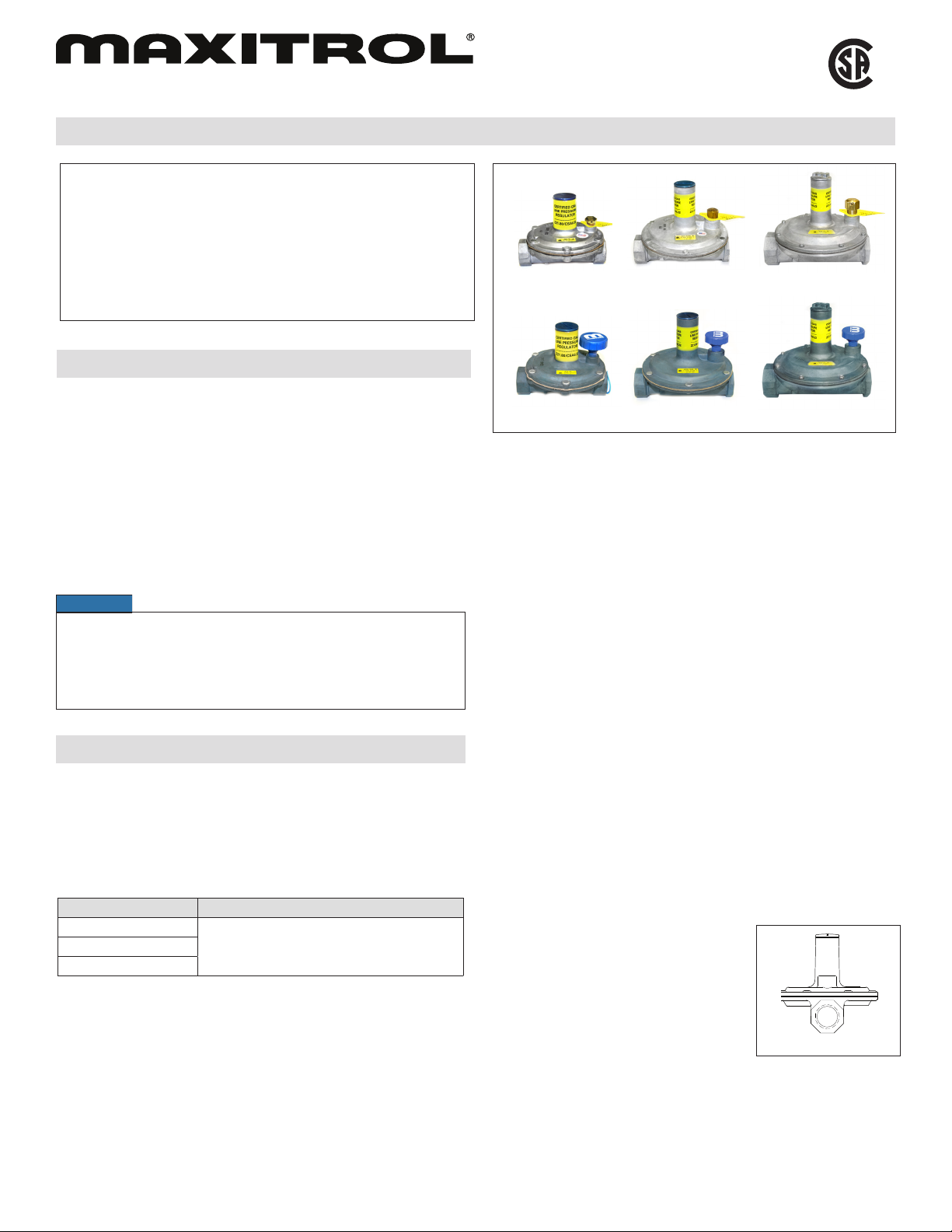
325-3L
325-3BL 325-5ABL
Figure 1: 325 Series Line Pressure Regulators
325-5AL
C
325-7AL
325-7ABL
US
Maximum Individual Load
Largest single appliance served by the regulator.
325-3(B)L ...............................................................140,000 Btu/hr
325-5A(B)L ............................................................ 300,000 Btu/hr
325-7A(B)L .........................................................1,250,000 Btu/hr
NOTICE
These regulators provide no downstream over-pressure protection
in the event of failure. At supply pressures in excess of 2 psi,
they should not be used. For Technical Support contact a Maxitrol
Technical Support Representative. See Maxitrol Safety Warning
Instructions, GPR_CSA_2PSI_MI_EN.FR
SPECIFICATIONS
Gases
Suitable for natural, manufactured, mixed gases, liqueed
petroleum gases, and LP gas-air mixtures.
Approvals
CSA: ANSI Z21.80/CAN 6.22
Maximum Inlet Pressure
Model CSA Certied
325-3(B)L
2 psi (13.8 kPa)325-5A(B)L
325-7A(B)L
Minimum Inlet Pressure
CSA Certied...............................................................1 psi (7 kPa)
Outlet Pressure Range
Certied Spring ............................................................. 7 - 11” w.c.
Emergency Exposure Limits
All Models (Inlet Side Only) ................................ 65 psi (450 kPa)
Capacity
Total load of multiple appliances combined.
325-3(B)L (3/8”, 1/2”) .............................................. 250,000 Btu/hr
325-5A(B)L (1/2”) ................................................... 425,000 Btu/hr
325-5A(B)L (3/4”, 1”) .............................................. 550,000 Btu/hr
325-7A (B) L (1 1/4”, 1 1/2”) ..................................1,250,000 Btu/hr
NOTE: Capacity table is used to determine the maximum multiple
appliance load. The largest single appliance served by
the regulator should not exceed the maximum individual
load specied above.
Ambient Temperature Limits
All Models ..................................... -40ºF to 205ºF (-40ºC to 96ºC)
Vent Pipe Connections
325-3(B)L ....................................................................... 1/8” NPT
325-5A(B)L ..................................................................... 3/8” NPT
325-7A(B)L ..................................................................... 1/2” NPT
Mounting Position
The 325 Series is suitable for multi-poise
mounting, but when used with a vent
limiting device, the regulator must be
mounted in a horizontal upright position
(see Figure 2). Install the regulator
properly with gas owing as indicated
by the arrow on the casting. (See
Maxitrol Safety Warning Instructions,
GPR_CSA_2PSI_MI_EN.FR).
UPRIGHT
Figure 2: 325 Regulator
in Upright Postion
© 2011 Maxitrol Company, All Rights Reserved.
1
Page 2
325 Series Line Pressure Regulators
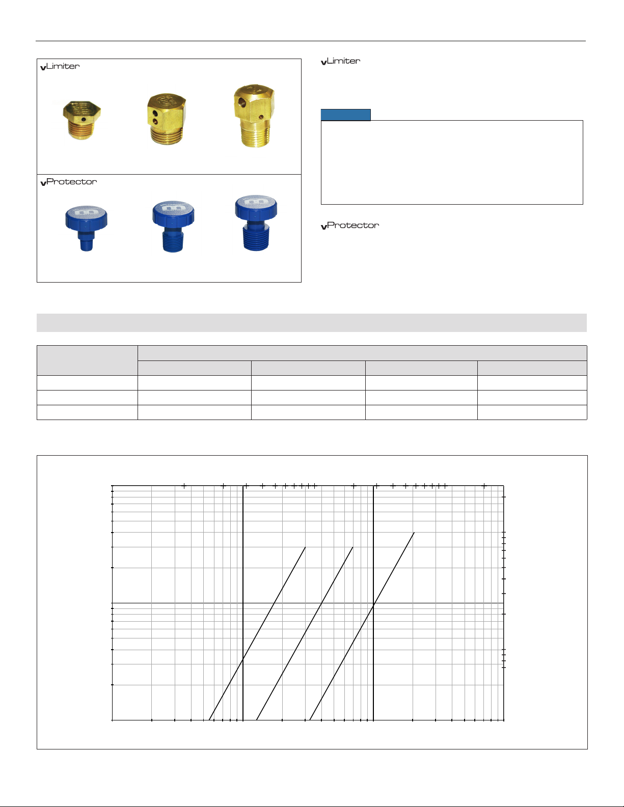
12A09 (1/8” NPT)
Figure 3: Vent Accessories
®
Vent Limiting Devices
®
Vent Protectors
13A15 (1/8” NPT)
12A39 (3/8” NPT)
13A15-5 (3/8” NPT)
12A49 (1/2” NPT)
13A25 (1/2” NPT)
®
Vent Limiting Devices for Indoor Applications
325-3(B)L ...........................................................................12A09
325-5A(B)L .........................................................................12A39
325-7A(B)L .........................................................................12A49
NOTICE
Maxitrol vent limiting devices eliminate the need to run vent
piping to the outside. Vent limiting devices are designed for
use indoors and in spaces where limiting the amount of gas
escapement due to diaphragm failure is critical. Vent limiting
devices should not be used outdoors if they are exposed
to the environment. Vent protectors are available for all
outdoor applications to ensure proper vent protection.
®
Vent Protectors for Outdoor Applications
325-3(B)L ............................................................................13A15
325-5A(B)L ......................................................................13A15-5
325-7A(B)L .........................................................................13A25
PRESSURE DROP: 0.64 sp gr gas expressed in CFH (m
Model Number
7.0” w.c. (1.7 kPa) 1/2 psi (3.4 kPa) 3/4 psi (5 kPa) 1 psi (7 kPa)
3
/h) (for system pressure drop calculations)
Pressure Drop
325-3(B)L 145 (4.0) 204 (5.8) 250 (7.0) 289 (8.2)
325-5A(B)L 339 (9.6) 476 (13.5) 583 (16.5) 673 (19.1)
325-7A(B)L 815 (23.1) 1149 (32.5) 1405 (39.8) 1624 (46.0)
NOTE: All Maxitrol line pressure regulators must be installed and operated in accordance with Maxitrol’s Safety Warning Instructions.
Flow Rate (m3 @ 0.64 SG gas)
100
10
Pressure Drop (in. w.c.)
1 2 3 4 5 6 8 10 20 30 40 60 80 100 200
L
)
B
(
3
5-
2
3
L
)
B
(
A
5
5-
2
3
L
)
B
(
A
7
5-
2
3
20
10
9
8
7
6
5
4
3
2
Pressure Drop (kPa)
1
.9
.8
.7
1
10 100 1000 10000
Figure 4: Pressure Drop Chart
© 2011 Maxitrol Company, All Rights Reserved.
Flow Rate (cfh @ 0.64 SG gas)
2
Page 3
325 Series Line Pressure Regulators
CAPACITIES: 0.64 sp gr gas expressed in CFH (m
Model Number
(pipe size)
325-3(B)L
(3/8”, 1/2”)
325-5A(B)L
(1/2”)
325-5A(B)L
(3/4”, 1”)
325-7A(B)L
(1 1/4”, 1 1/2”)
Outlet Pressure
Set Point
7.0” w.c. (1.7 kPa)
10.0” w.c. (2.5 kPa)
7.0” w.c. (1.7 kPa)
10.0” w.c. (2.5 kPa)
7.0” w.c. (1.7 kPa)
10.0” w.c. (2.5 kPa)
7.0” w.c. (1.7 kPa)
10.0” w.c. (2.5 kPa)
3
/h)
Operating Inlet Pressure
1 psi (7 kPa) 1 1/2 psi (10 kPa) 2 psi (13.8 kPa)
250
(7.1)
230
(6.5)
425
(12.0)
425
(12.0)
550
(15.6)
535
(15.1)
1250
(35.4)
1125
(31.9)
250
(7.1)
250
(7.1)
425
(12.0)
425
(12.0)
550
(15.6)
550
(15.6)
1250
(35.4)
1250
(35.4)
250
(7.1)
250
(7.1)
425
(12.0)
425
(12.0)
550
(15.6)
550
(15.6)
1250
(35.4)
1250
(35.4)
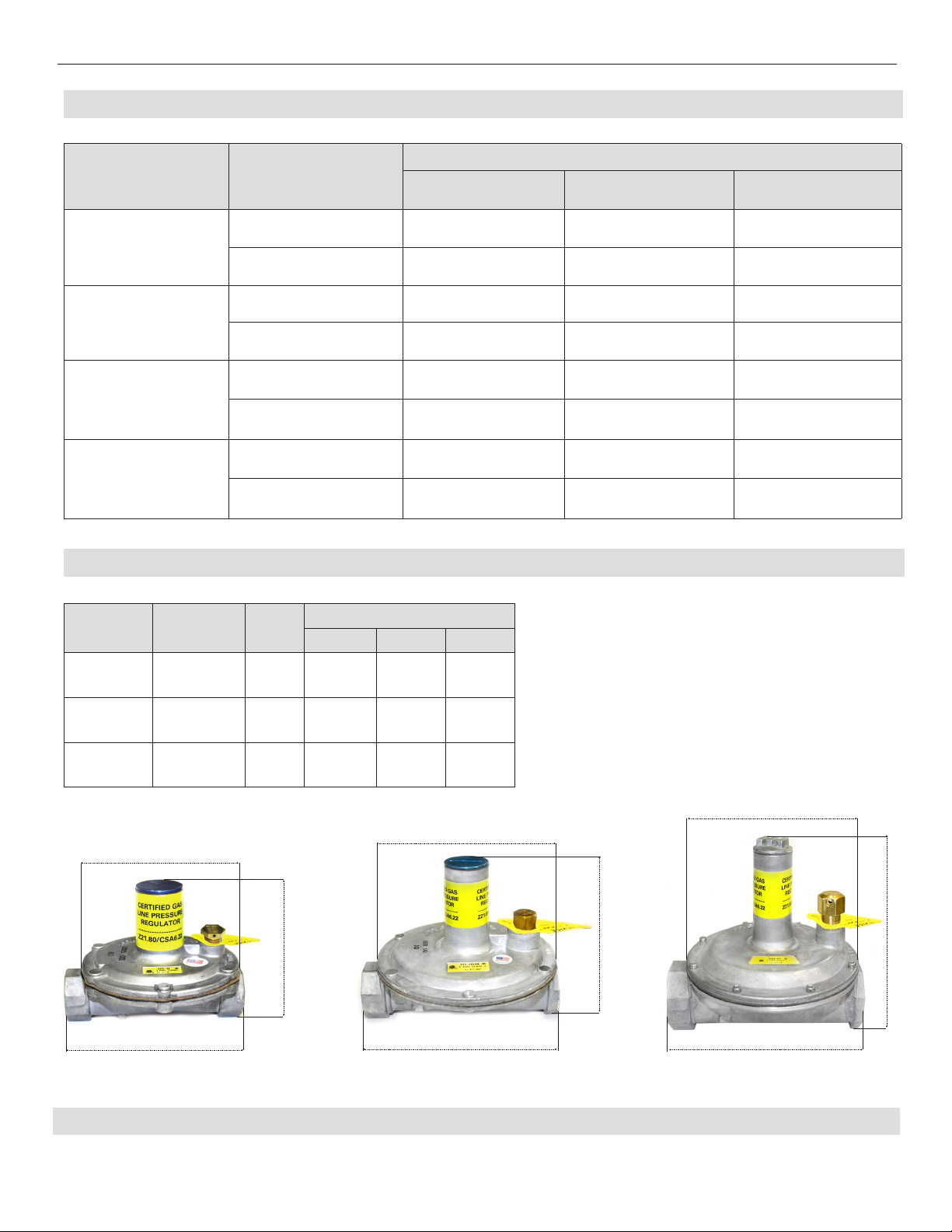
DIMENSIONS: Expressed in inches (mm)
Model
Number
325-3(B)L 3/8”, 1/2”
325-5A(B)L 1/2”, 3/4”, 1”
325-7A(B)L 1 1/4”, 1 1/2”
* Standard models NPT threads
Pipe
Size*
Swing
Radius
3
(76)
4 7/8
(124)
6 1/8
(156)
Dimensions
A B C
3 1/2
(89)
5 1/4
(133)
7 1/4
(184)
4 1/4
(108)
5 7/8
(149)
8
(203)
C
A
NOTE: Dimensions are to be used only as an aid in designing
clearance for the regulator. Actual production
dimensions may vary somewhat from those shown.
3 7/8
(98)
5 7/16
(138)
7
(178)
C
C
A
A
B
325-3(B)L
© 2011 Maxitrol Company, All Rights Reserved.
B
325-5A(B)L
3
B
325-7A(B)L
Page 4

325 Series Line Pressure Regulators
SPRING RANGE SELECTION
Outlet Pressure Range (all models):
Certied Spring .................................................. 7 - 11” w.c.
SIZING INSTRUCTIONS
When 325 Series regulators are used on 2 psi piping systems, often times the 2 psi systems are sized with a 1 psi pressure drop through
the copper or stainless steel tubing. This means there will be 2 psi at the inlet of the regulator under no ow conditions, and 1 psi at the
regulator inlet under maximum ow conditions.
TO SELECT A LINE PRESSURE REGULATOR OF SUFFICIENT FLOW - ONE MUST KNOW:
1. Available inlet pressure (maximum static/minimum operating).
2. Desired outlet pressure.
3. Required maximum capacity (total load, all appliances combined) and maximum individual load.
4. Pipe size.
Example: To select a 325 series regulator of sufcient capacity to handle ow...
KNOWN:
A. Required: 1/2” NPT line regulator, outlet pressure of 7” w.c., with static pressure of 2 psi, and a minimum operating inlet
pressure of 1 psi.
B. Combined BTU rating of all appliances to be served by the regulator: 145,000 Btu/hr.
C. Largest single appliance’s BTU rating: 90,000 Btu/hr
SOLUTION:
A. In the Capacities Table (page 3), locate rows where 1/2” (pipe size) models with 7” w.c. outlet pressure intersect with 1 psi
operating inlet pressure column. (325-3L = 250 CFH, 325-5AL = 425 CFH).
B. The total BTU load requirement cannot exceed the requirement, and does not exceed either model’s capacity.
C. The 90,000 Btu/hr single largest appliance rating is below the 325-3L maximum individual load capacity of 140,000 Btu/hr.
D. The 325-3L is the correct line regulator for this application.
Maxitrol Company
23555 Telegraph Rd., P.O. Box 2230
Southeld, MI 48037-2230 U.S.A.
LPR_MS_EN_09.2011
Replaces 325LPR_MS_EN
www.maxitrol.com
4
© 2011 Maxitrol Company,
All Rights Reserved.
 Loading...