

maxitrak 5 Inch Gauge Alice User Manual
info@maxitrak.co.uk Copyright maxitrak 2010
info@maxitrak.co.uk Copyright maxitrak 2010
Alice kit instructions
Please read through the instructions and familiarize your self with the parts before starting. Left
and right hand sides refer to the engine as seen from the drivers point of view. Copper pipe work
gets work hardened, if you are struggling to get it bent to shape you can anneal (soften) it by
getting it red hot and plunging in to water. Be careful not to melt any solder joints or fittings, you
can do this any number of times until the pipe is correct. Be careful on tight bends, squeeze the
pipe across its width in a vice if it begins to flatten.
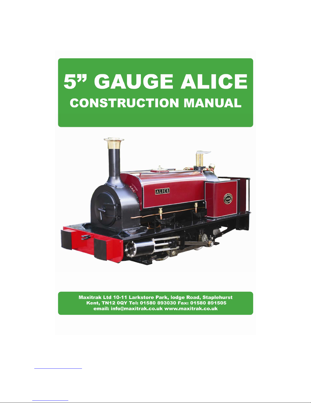
1. The chassis comes complete and may be run on air before commencing with the kit build. The
pipe work from the axle pump to the back of the engine should be removed for ease of build, be
sure not to lose the ball from the top of the pump. Put the washers and banjo bolt back in the pump
for safe keeping.
2. Screw the blast pipe into the top of the valve block, center hole. This pipe will need to be
centralized under the chimney when the smoke box is in place. It is quite soft and can be bent to
shape as required.
info@maxitrak.co.uk Copyright maxitrak 2010
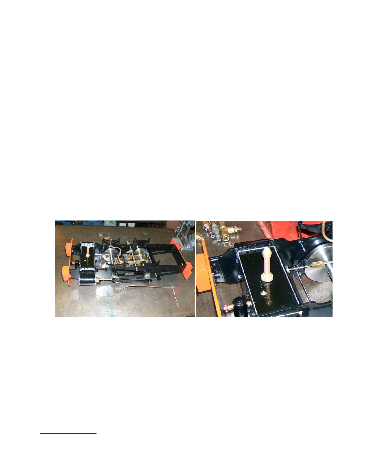
3. Take the smoke box and try in the frames, there are two spacers that go between the frame and
the smoke box, bolt on with M4 bolts, nuts inside the smoke box. Leave lose until fully assembled
with the boiler.
NB The smoke box assembly needs to be air tight, and requires sealing round the base with
heatproof silicone or car exhaust filler after final assembly.
4. Lay the boiler in the frames, supporting the firebox on a suitable block of wood. The front of the
boiler can now be introduced in to the back of the smoke box. The front of the boiler is quite soft
copper and can be worked with a small hammer if out of shape. Position the boiler so the bolts can
be fitted through the frame and into the threaded blocks on the firebox side. (M5) Once in place
the retaining bolt holes can be drilled in to the front of the boiler, bolts are M3 by 25 brass, drill the
hole 3.5mm dia.
NB It is most important that these bolts go into the front lip of the boiler, not into the pressure
vessel. Just mark the boiler with the point of the drill, remove the boiler and make sure the hole is
going through the front lip only. Replace the boiler and continue drilling when you are sure the fit
is correct. Do not put the boiler too far into the smoke box. The bolts go through the holes in the
side of the smoke box, the three tapped holes near the top are for the tank fixing.
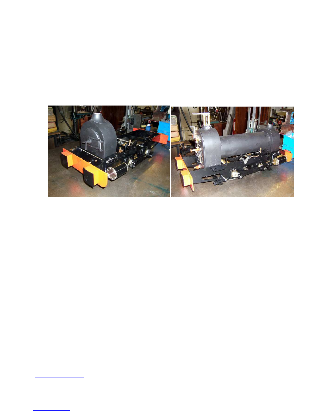
5. The firebox end of the boiler can now be secured to the frame, the bolts on the left side go
through the hand pump support angle bracket, the frame, and into the tapped boiler side blocks.
(M5 by 12) On the right side the bolts also go through the reverser stand and the angle bracket has
a larger hole for the brake stand, (M5 by 16). Smoke box and boiler bolts can be given a final
tighten and the smoke box sealed. Fit the chimney and chimney top to the smoke box.
info@maxitrak.co.uk Copyright maxitrak 2010
6. The reverser stand assembly should be connected up, the reach rod runs outside the dummy
springs and on to the weigh shaft lever on the frame side. Check that the lever works full stroke
and the valve gear moves in to full forward and back position.
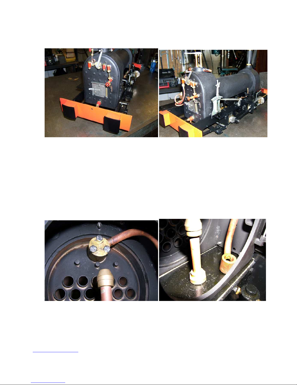
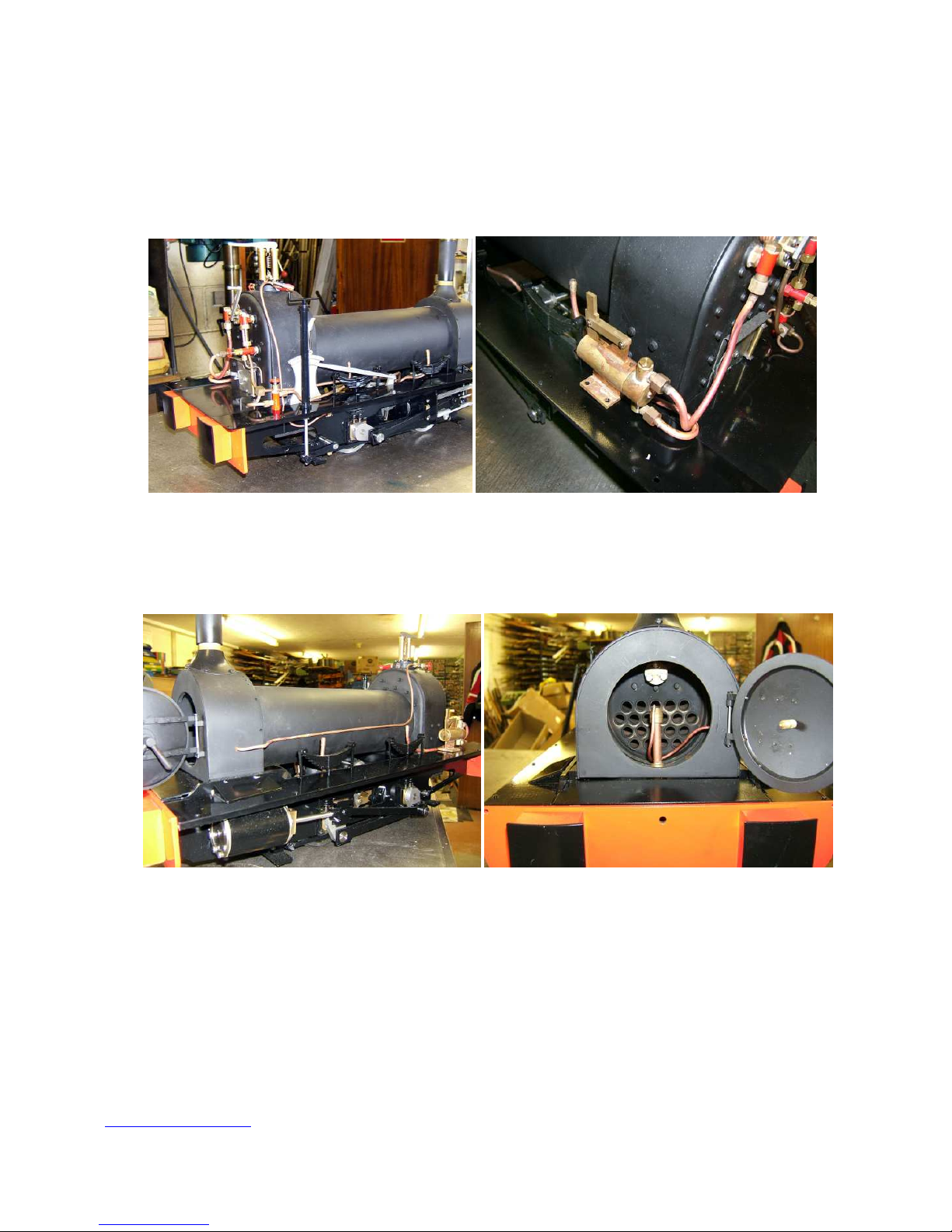
7. The main steam pipe in the smoke box can now be fitted. This needs to be shaped to fit between
the front of the boiler and the threaded hole in the top of the valve block.
Make sure the O ring is in place on the front of the boiler outlet pipe, fix in place with 3 M4 by 20
stainless bolts. The bottom of the pipe is connected to the valve block with a brass banjo bolt,
sealed with washers top and bottom.

info@maxitrak.co.uk Copyright maxitrak 2010
8. Take the four slide bars and fit them to the back covers of the cylinders, M4 hex bolts. The
motion brackets can now be fitted to the other end of the slide bars, using M3 round head screws.
Check you have left and right hand correct, the curved top of the motion bracket should be
horizontal ready to bolt to the footplate.
9. You can now put the footplate on left side. M2 hex screws in the rear buffer beam and the
motion bracket, M3 round head in the front buffer beam. Check the holes line up for the hand
pump bracket, drill or file out the footplate to fit, check this with the hand pump its self as well.
Before fitting the right footplate bend up the whistle pipe (E) and fit it to the whistle valve, so as to
fit through the cut out in the footplate behind the reverser stand.
10. The bypass valve and axle pump pipe work can now be fitted to the right side of the engine,
bend the feed pipe to get to the check valve on the right of the regulator. The return pipe from the
bypass valve (A) can be fitted but the other end can be left until the tank is in place.
info@maxitrak.co.uk Copyright maxitrak 2010
11. The hand brake stand and handle can now be fitted through the footplate and angle bracket on
the right hand side. The screwed end of the handle goes into the brake lever on the chassis, directly
under the brake handle.
12. The hand pump is fitted to the holes in the left foot plate, bend up the pipe to go from the top
of the pump to the check valve on the left of the regulator. The longer hand pump pipe is bent in a
tight curve to lay along side the pump base and then turns up to match the feed from the tank.
Pipes B and C.
13. The blower pipe (D) can be bent to shape so as to run from the blower valve down the side of
the firebox and along the boiler under where the tank sits. It is then bent to go round the smoke box
and in through the hole in the side of the smoke box. Inside it needs to be shaped so the nozzle end
lays beside the blast pipe and points directly at the base of the chimney. Hold it in place with a
twist of copper wire round the blast pipe.
 Loading...