

MAXINCOM MUC1004, MUC2008, MUC2016 Administrator's Manual

MUC1004/2008/2016 Administrator guide
Http://www.maxincom.com 1 / 112
MUC1004/2008/2016
IP PBX
Administrator guide V1.1
Version 12.1.0.14
Xiamen Maxincom Technologies Co., Ltd.

MUC1004/2008/2016 Administrator guide
Http://www.maxincom.com 2 / 112
Table of Contents
1. Introduction .............................................. 5
1.1 Overview ............................................................................................... 5
1.2 Product Features .................................................................................... 5
1.3 Product Appearance ................................................................................ 6
1.4 Scenario of Application ............................................................................ 9
2. Installation Guide .................................... 10
2.1 Installation Notice ................................................................................. 10
2.2 Installation Procedure ........................................................................... 10
2.2.1 Connect Drawing ......................................................................... 10
3. WEB Interface Configuration .................. 11
3.1 Access MUC2008 unit ............................................................................ 11
3.2 Parameters Configuration ...................................................................... 12
3.3 System Information .............................................................................. 13
3.3.1 System Information ..................................................................... 13
3.3.2 Extensions Status ........................................................................ 14
3.3.3 Trunk Status ............................................................................... 14
3.4 Network Configuration .......................................................................... 15
3.4.1 LAN Configuration ....................................................................... 15
3.4.2 VLAN Configuration ..................................................................... 17
3.4.3 ARP Configuration ....................................................................... 19
3.4.4 VPN Configuration ....................................................................... 20
3.4.5 DDNS Server............................................................................... 21
3.4.6 Static Route ................................................................................ 21
3.4.7 DHCP Server ............................................................................... 23
3.5 Trunks ................................................................................................. 24
3.5.1 Physical Trunks(PSTN and GSM Trunks) ........................................ 24
3.5.2 IP Trunk (Peer to Peer Mode) ....................................................... 28

MUC1004/2008/2016 Administrator guide
Http://www.maxincom.com 3 / 112
3.5.3 VoIP Trunk ................................................................................. 30
3.6 PBX Basic ............................................................................................. 34
3.6.1 Extensions .................................................................................. 34
3.6.2 Feature Codes............................................................................. 45
3.6.3 Speed dial .................................................................................. 49
3.6.4 Outbound Routes ........................................................................ 50
3.6.5 Parking Lot ................................................................................. 54
3.6.6 Time Groups ............................................................................... 55
3.6.7 General Preferences .................................................................... 57
3.7 PBX Inbound Call Control ...................................................................... 59
3.7.1 Inbound Routes .......................................................................... 59
3.7.2 Blacklist ...................................................................................... 64
3.7.3 IVR ............................................................................................ 64
3.7.4 Queue ........................................................................................ 67
3.7.5 Ring Groups ................................................................................ 71
3.7.6 Conferences ............................................................................... 73
3.7.7 Callback ..................................................................................... 75
3.8 PBX Advanced Settings ......................................................................... 76
3.8.1 SIP settings ................................................................................ 76
3.8.2 IAX Setting ................................................................................. 82
3.8.3 PIN Sets ..................................................................................... 83
3.8.4 PIN Users ................................................................................... 84
3.8.5 DISA .......................................................................................... 85
3.8.6 Paging and Intercom ................................................................... 87
3.9 Voice Management ............................................................................... 88
3.9.1 System Recordings ...................................................................... 88
3.9.2 Music on Hold ............................................................................. 89
3.9.3 Voicemail Settings ....................................................................... 91
3.9.4 System Prompts Settings ............................................................. 92
3.10 System Preferences ............................................................................ 94

MUC1004/2008/2016 Administrator guide
Http://www.maxincom.com 4 / 112
3.10.1 Firewall Rules ............................................................................ 94
3.10.2 Security Info ............................................................................. 96
3.10.3 Firmware update ....................................................................... 97
3.10.4 Data Backup ............................................................................. 99
3.10.5 Data Restore ............................................................................. 99
3.10.6 Password ................................................................................. 100
3.10.7 Time & Date ............................................................................ 100
3.10.8 Reset ...................................................................................... 101
3.10.9 Reboot .................................................................................... 101
3.11 Phone Provisioning............................................................................. 102
3.11.1 General Settings ....................................................................... 102
3.11.2 Phones .................................................................................... 103
3.12 Reports ............................................................................................. 104
3.12.1 CDR Report .............................................................................. 104
3.12.2 System Logs ............................................................................ 105
3.12.3 Firewall Logs ............................................................................ 106
3.12.4 Trace Logs ............................................................................... 106
3.13 System tools ..................................................................................... 108
3.13.1 SMTP Parameter ...................................................................... 108
3.13.2 AMI Settings ............................................................................ 109
3.13.3 Ping ........................................................................................ 110
3.13.4 Tracert .................................................................................... 110
3.13.5 Packet Capture ......................................................................... 111
3.13.6 Text to Wav ............................................................................. 112
3.13.7 Certificates .............................................................................. 112

MUC1004/2008/2016 Administrator guide
Http://www.maxincom.com 5 / 112
1. Introduction
1.1 Overview
MUC Series PBX—IP PBX for Small Business/Home Office
MUC1004/2008/2016 IP PBX is a standalone embedded hybrid PBX for small
businesses and remote branch offices of larger organizations. It is designed to
bring enterprise-grade Unified Communications and Security Protection in an
easy-to-manage fashion.
1.2 Product Features
● Alert
● Firewalls
● Blacklist
● HTTPS
● Call Back
● Integrated built-in packet capture
tools
● Call Detail Records(CDR)
● Interactive Voice Response (IVR)
● Call Forward,Call Parking
● Intercom/Zone Prompt
● Call Pickup
● Music On Hold
● Call Recording
● Open VPN
● Call Routing
● Paging/Intercom
● Call transfer
● Phone Provisioning
● Call Waiting
● PIN Users
● Caller ID
● QoS
● Conference
● Queue
● DDNS
● Ring Group
● Define Office Time
● Speed Dial
● Direct Inward System Access
(DISA)
● Spy functions
● Distinctive Ringtone
● Static Route
● Do Not Disturb(DND)
● VLAN
● External Storage
● Voicemail
●T.30,T.38 Faxes
●Alert Settings
●IP Blacklist
●AMI Settings
●Extension CDR
MUC1004/2008/2016 Administrator guide
Http://www.maxincom.com 6 / 112
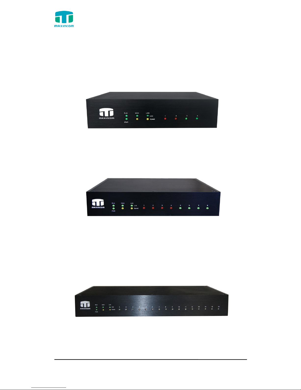
1.3 Product Appearance
The appearance of MUC1004/2008/2016 shows as follow
Figure 1-3-1 Front view of MUC1004
Figure 1-3-2 Front view of MUC2008
Figure 1-3-3 Front view of MUC2016
MUC1004/2008/2016 Administrator guide
Http://www.maxincom.com 7 / 112
Table 1-3-1 Description of Front view
Index
Indicators
Description
1
RUN
On: Starting
Off: Abnormal
Blinking every 0.5s: Normal status
2
PWR
On: Power on
Off: Power off
3
WAN,LAN
Green LED: indicates the Internet interface is in Link .
Yellow LED: ON is indicates 100MBps Ethernet port.
4
1~4,(5~8),
(9~16)
Red LED stands for FXO port
Orange LED indicates presence of a BRI port.
Green LED stands for FXS port
Red LED blinks: FXO port isn‟t connected to PSTN line.
Alternately blinks Red and Green: FXO port has an
incoming call.
Alternately blinks Red and Green fast: FXO port is in a
call.
Alternately blinks Green and Red: FXS port is ringing.
Alternately blinks Green and Red fast: FXS port is in a
call.
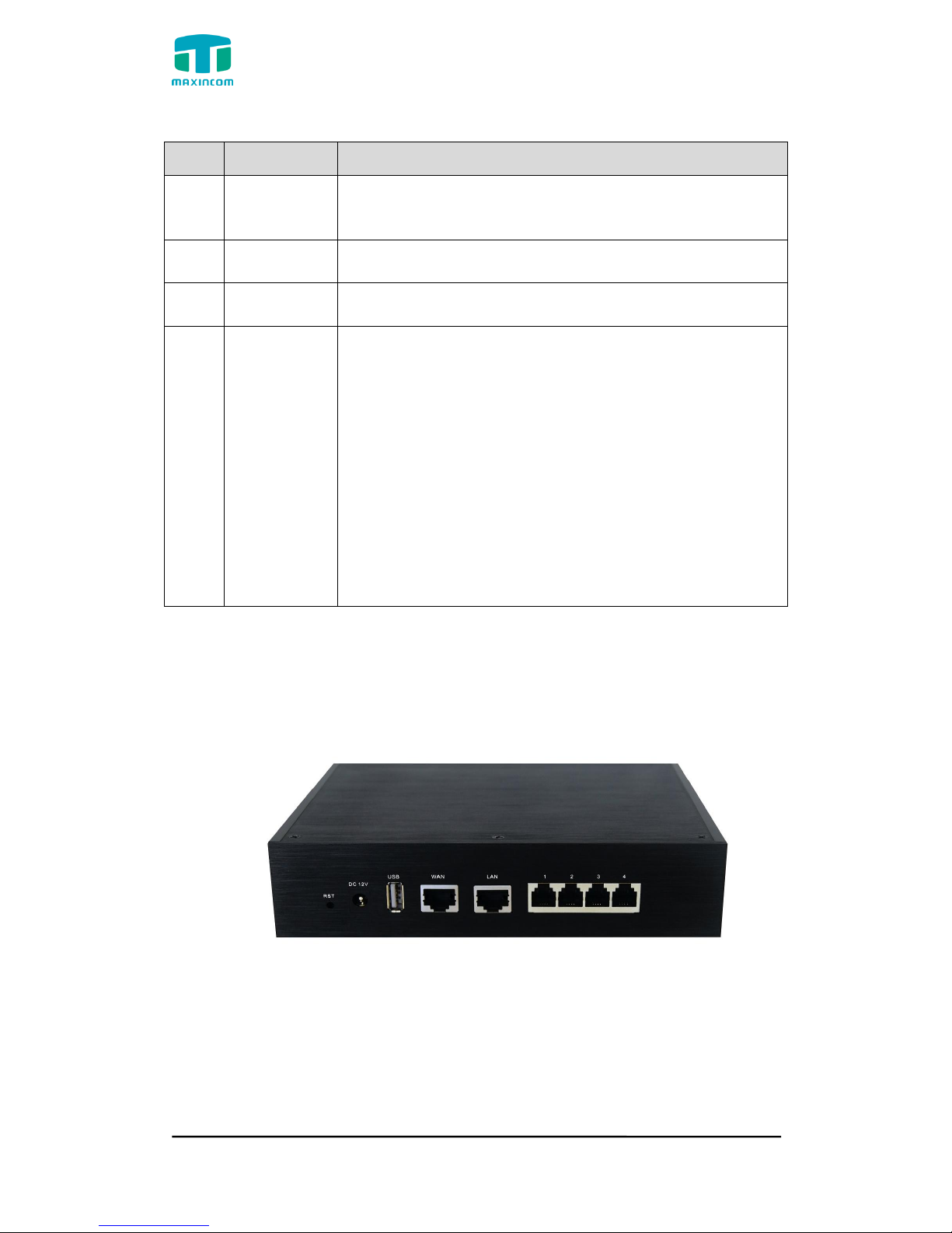
Figure 1-3-4 Rear view of MUC1004

MUC1004/2008/2016 Administrator guide
Http://www.maxincom.com 8 / 112
Figure 1-3-5 Rear view of MUC2008
Figure 1-3-6 Rear view of MUC2016
Table 1-3-2 Description of Rear view
Index
Interface
Description
1
RST
Reset button to restore default IP and password or
restore factory setting.
Hold RST button 8 seconds, RUN LED being ON during
this time
2
DC 12V
Power connector of DC power. Input: DC12V 3A/DC12
MUC1004/2008/2016 Administrator guide
Http://www.maxincom.com 9 / 112
1A(MUC1004 only)
3
USB
For the storage of call recording files
4
WAN,LAN
MUC2008 provides two 10/100 adaptive RJ45 Ethernet
ports, marked as LAN and WAN.
-LAN port :LAN port is for the connection to Local Area
Network
-WAN port:WAN port is the netword port for the
connection to internet. It supports “DHCP
server”,”PPPoE/dynamic DNS”,and”static IP”for IP
address assignment.
5
1~4,(5~8),
(9~16)
FXO port(red light):For the connection of PSTN lines or
FXS port of traditional PBX.MU2008 uers could make or
receive calls via FXO port.
FXS port(green light):For the connection of analog
phones.
BRI port(orange port):For the connection of ISDN BRI
lines. MU2008 uers could make or receive calls via BRI
port.
Note:The sequence number of the port corresponds to
that of the indicator lights in the front panel.
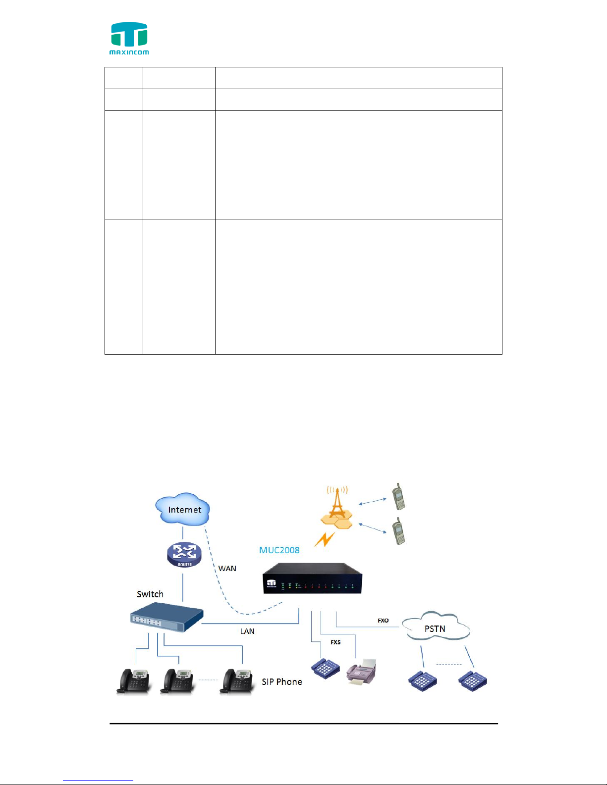
1.4 Scenario of Application
Application 1
Figure 1.4.1

MUC1004/2008/2016 Administrator guide
Http://www.maxincom.com 10 / 112
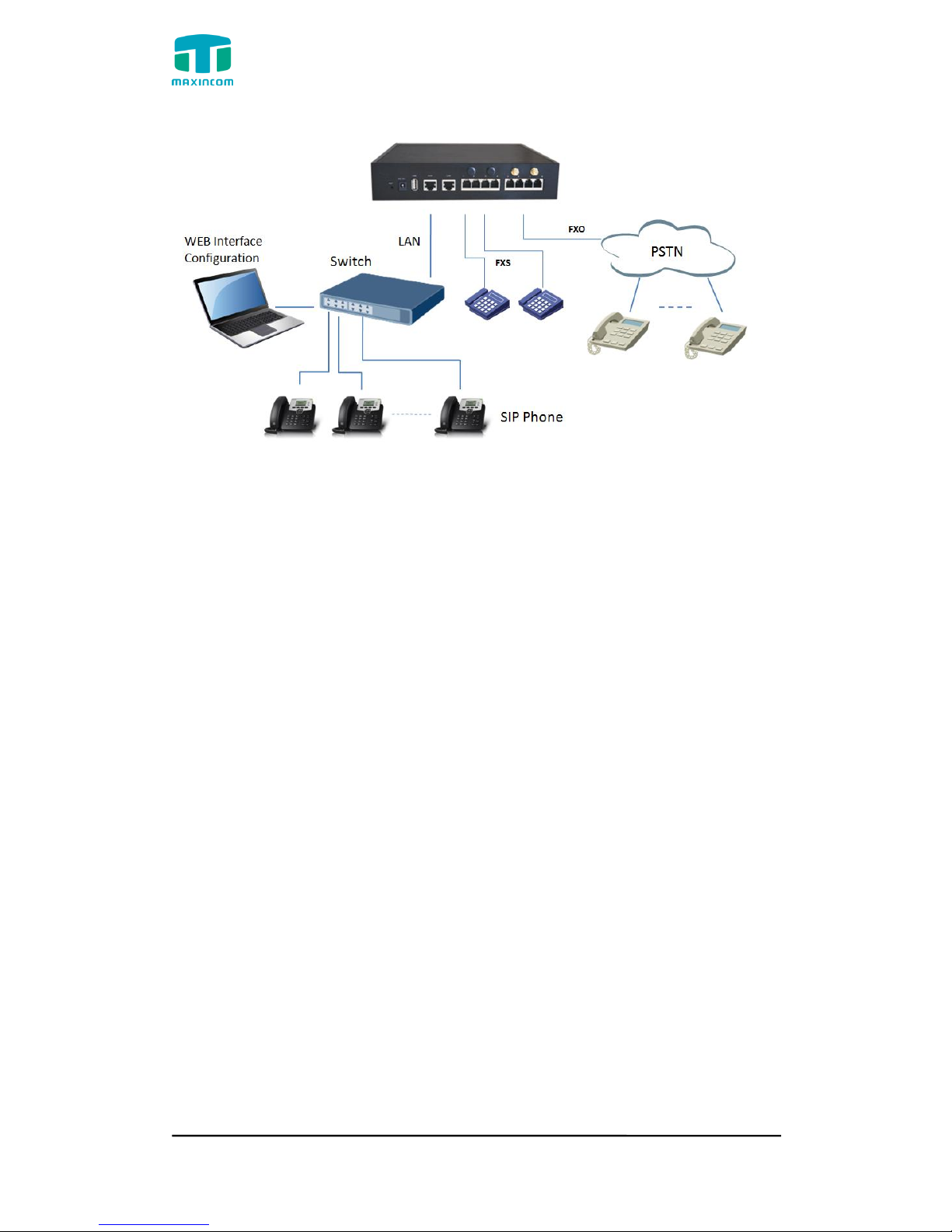
Application 2
Figure 1.4.2
2. Installation Guide
2.1 Installation Notice
We use the MUC2008 device as an installation case as follows:
MUC2008 adapts 12VDC Power adapter, make sure AC power supply grounded
well to ensure the reliability and stability;
Notes: incorrect power connection may damage power adapter and device.
MUC2008 provides standard RJ45 with 10Mbps or 100Mbps interfaces.
2.2 Installation Procedure
2.2.1 Connect Drawing
Figure 2.2.1 Connect Drawing
MUC1004/2008/2016 Administrator guide
Http://www.maxincom.com 11 / 112
3. WEB Interface Configuration
PBX IP PBX has the same web interface. This charpter describes web
configuration of PBX. The PBX contains an embedded web server to set
parameters by using the HTTP protocol. We are strongly recommend
to access device with Google Chrome or Firefox Browser.
We use the MUC2008 device as a configuration case as follows:
3.1 Access MUC2008 unit
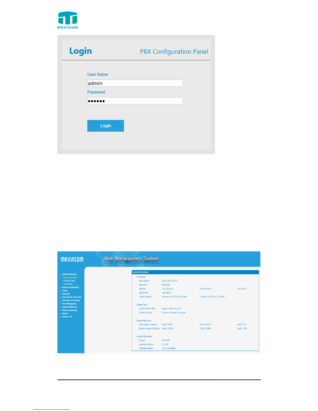
Enter IP address of MUC2008 in IE/Google Chrome/Firefox Browser. The
default IP of LAN port is 192.168.6.200. and the GUI shows as below:
In this example, the IP address is 192.168.6.91
Figure 3.1.1 WEB login interface
MUC1004/2008/2016 Administrator guide
Http://www.maxincom.com 12 / 112
Enter username and password and then click “Login” in configuration interface.
The default username and password are “admin/admin”. It is strongly
recommended, change the default password to a new password for system
security .
3.2 Parameters Configuration
PBX WEB configuration interface consists of the navigation tree and the detail
configuration interfaces.
Figure 3.2.1 WEB introduction
Go through navigation tree, user can check, view, modify, and set the device
configuration on the right of configuration interface.
MUC1004/2008/2016 Administrator guide
Http://www.maxincom.com 13 / 112
3.3 System Information
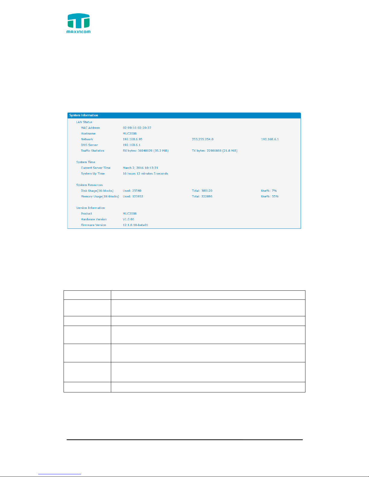
System information interface shows the basic information of status information,
mobile information and SIP information.
3.3.1 System Information
Figure 3.3.1 system Information
Table 3.3.1 System Information
Parameters
Description
MAC Address
Displays the current MAC of the gateway, for example:
70-B3-D5-1B-3D-02
Network
Current IP address and subnet mask of gateway
DNS Server
Displays DNS server IP address in the same network with the
gateway
System Up
Time
Shows the time period of the device running. For
example, :1h : 20m : 24s
Traffic
Statistics
Calculates the net flow, including the total bytes of message
received and sent。
Version info
Shows the current firmware version
MUC1004/2008/2016 Administrator guide
Http://www.maxincom.com 14 / 112
3.3.2 Extensions Status
Figure 3.3.2 Extensions Status
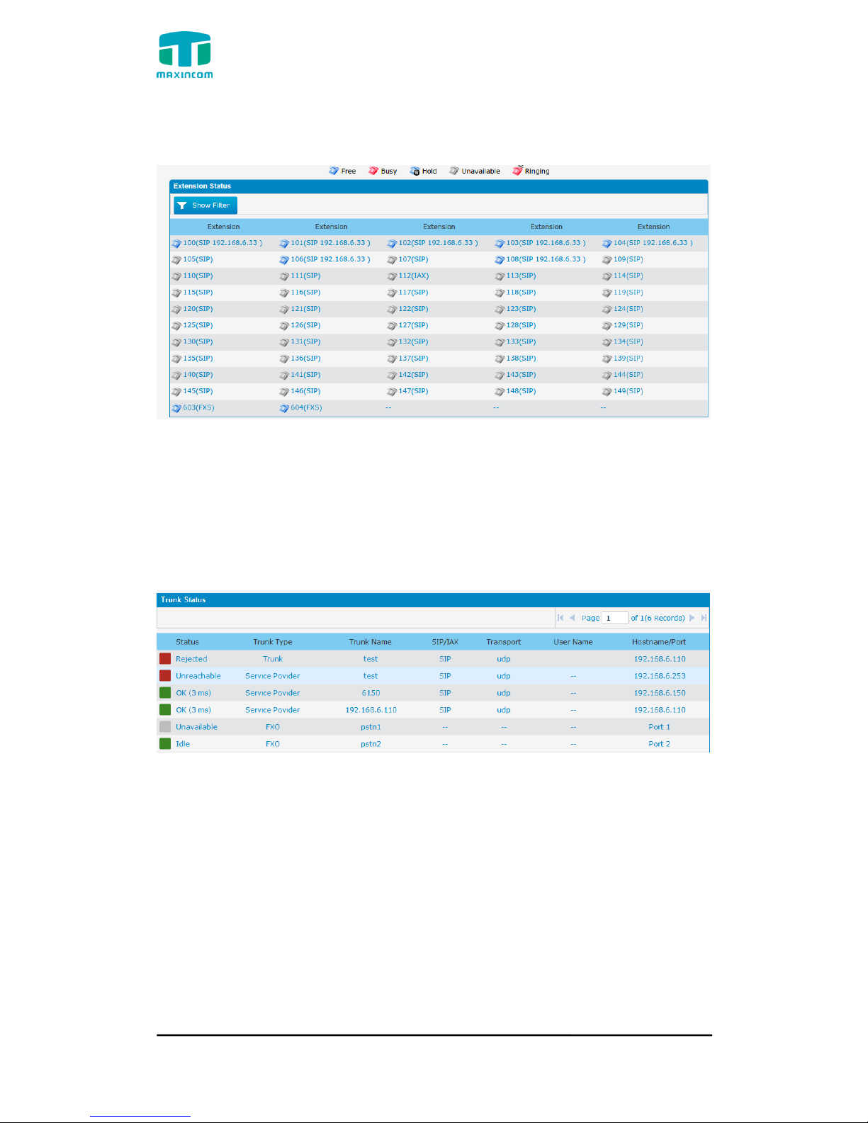
3.3.3 Trunk Status
Figure 3.3.3 Trunk Stratus
Trunk Status Description:
VoIP Trunk:
Status
Rejected: Trunk registration failed.
Registered: Successful registration, trunk is ready for use.
Request Send: Registering.
Waiting: Waiting for authentication.
Service Provider:
Status
OK: Successful registration, trunk is ready for use.

MUC1004/2008/2016 Administrator guide
Http://www.maxincom.com 15 / 112
Unreachable: The trunk is unreachable.
Failed: Trunk registration failed.
FXO Trunk:
Status
Idle: The port is idle.
Busy: The port is in use.
Unavailable: The port hasn‟t connected to the PSTN line.
More detail message, please refer to the LED indication of front panel.
Table 3.3.3 Trunk Status
Parameters
Description
Status
Shows the registration status of Trunk channel, including
registered and unregistered.
Trunk Type
Trunk mode will allow IP phone or IPPBX to register or trunk
mode to register to provider
Name
It describes this VoIP channel for the ease of identification. Its
value is character string
SIP/IAX
Choose the type of this trunk, SIP or IAX
Transfer
Protocol
This will be the transport method used by the trunk. The
options are UDP (default) or TCP or TLS.
User Name
The number for this VoIP channel
Hostname/IP
Address
Hostname or IP Address of this VoIP channel
3.4 Network Configuration
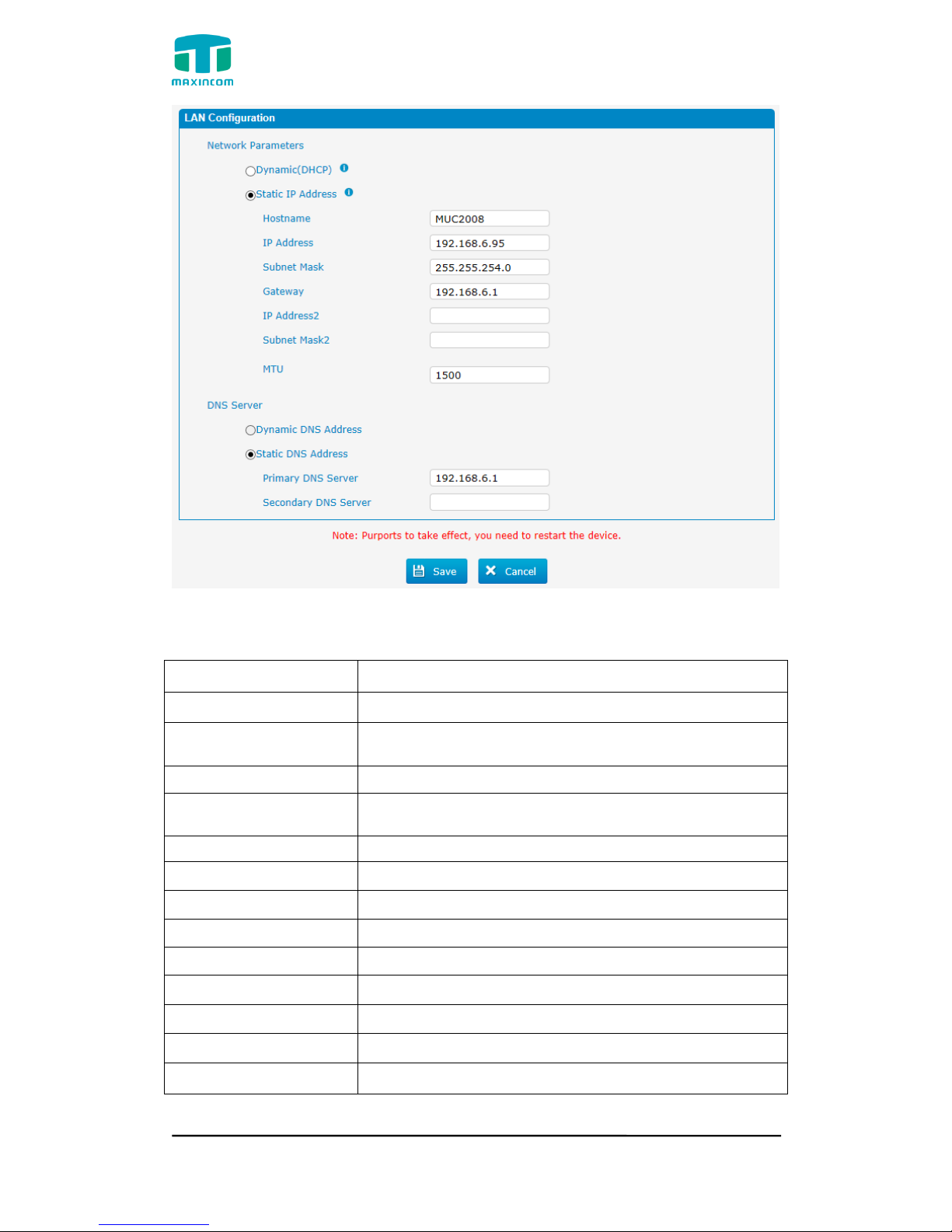
3.4.1 LAN Configuration
Figure 3.4.1 LAN Configuration
MUC1004/2008/2016 Administrator guide
Http://www.maxincom.com 16 / 112
Table 3.4.1 Description of Local network
Parameter
Description
Dynamic (DHCP)
Enable the device obtain IP Address automatically
Static IP Address
Configure the "IP Address", "Subnet Mask" and
"Default Gateway" by manual
Hostname
Set the host name for PBX
IP Address
Set the IP Address for PBX, It is recommended to
configure a static IP address for PBX
Subnet Mask
Set the subnet mask for PBX
Gateway
Set the gateway for PBX
IP Address 2
Set the second IP Address for PBX
Subnet Mask2
Set the second subnet mask for PBX
MTU
Message transmit unit, default is 1500
Dynamic DNS Address
Obtain DNS Server Address Automatically
Static DNS Address
Obtain Primary DNS Server by manual
Primary DNS Server
Set the primary DNS Server for PBX.
Secondary DNS Server
Set the Secondary DNS Server for PBX.
MUC1004/2008/2016 Administrator guide
Http://www.maxincom.com 17 / 112
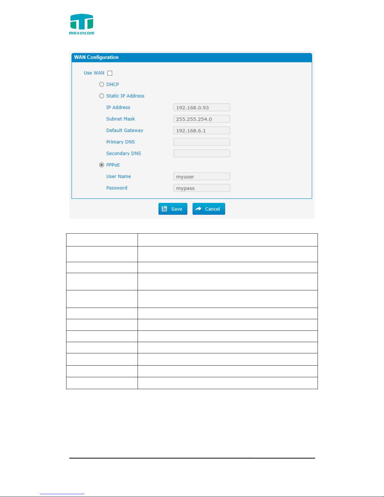
Figure 3.4.1.2 WAN Configuration
Table 3.4.1.2 Description of WAN Configuration
Parameter
Description
Use WAN
Enalbe use wan
Dynamic (DHCP)
Enable the device obtain IP Address automatically
Static IP Address
Configure the "IP Address", "Subnet Mask" and "Default
Gateway" by manual
IP Address
Set the IP Address for PBX, It is recommended to
configure a static IP address for PBX
Subnet Mask
Set the subnet mask for PBX
Default Gateway
Set the default gateway for PBX
Primary DNS
Set the primary DNS Server for PBX.
Secondary DNS
Set the Secondary DNS Server for PBX.
PPPoE
Use PPPoE to achieve IP address
User Name
PPPoE user name
Password
PPPoE password
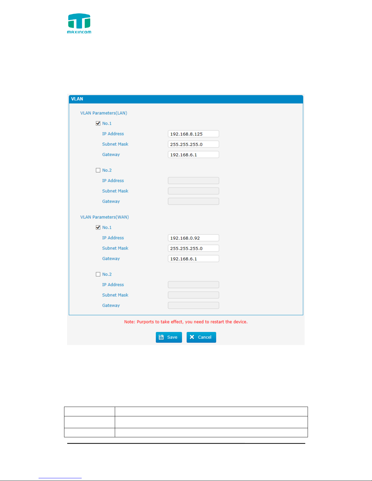
3.4.2 VLAN Configuration
A VLAN (Virtual LAN) is a logical local area network (or LAN) that extends
beyond a single traditional LAN to a group of LAN segments, given specific
configurations.
MUC1004/2008/2016 Administrator guide
Http://www.maxincom.com 18 / 112
Note: PBX is not the VLAN server, a 3-layer switch is still needed, please
configure the VLAN information there first, then input the details in PBX, so that
the packages via PBX will be added the VLAN label before sending to that
switch.
Figure 3.4.2 VLAN Configuration
Table 3.4.2 Description of VLAN Configuration
Parameter
Description
NO.1
Click the NO.1 you can edit the first VLAN over LAN
IP Address
Set the IP Address for PBX VLAN over LAN.
MUC1004/2008/2016 Administrator guide
Http://www.maxincom.com 19 / 112
Subnet Mask
Set the Subnet Mask for PBX VLAN over LAN.
Gateway
Set the Default Gateway for PBX VLAN over LAN
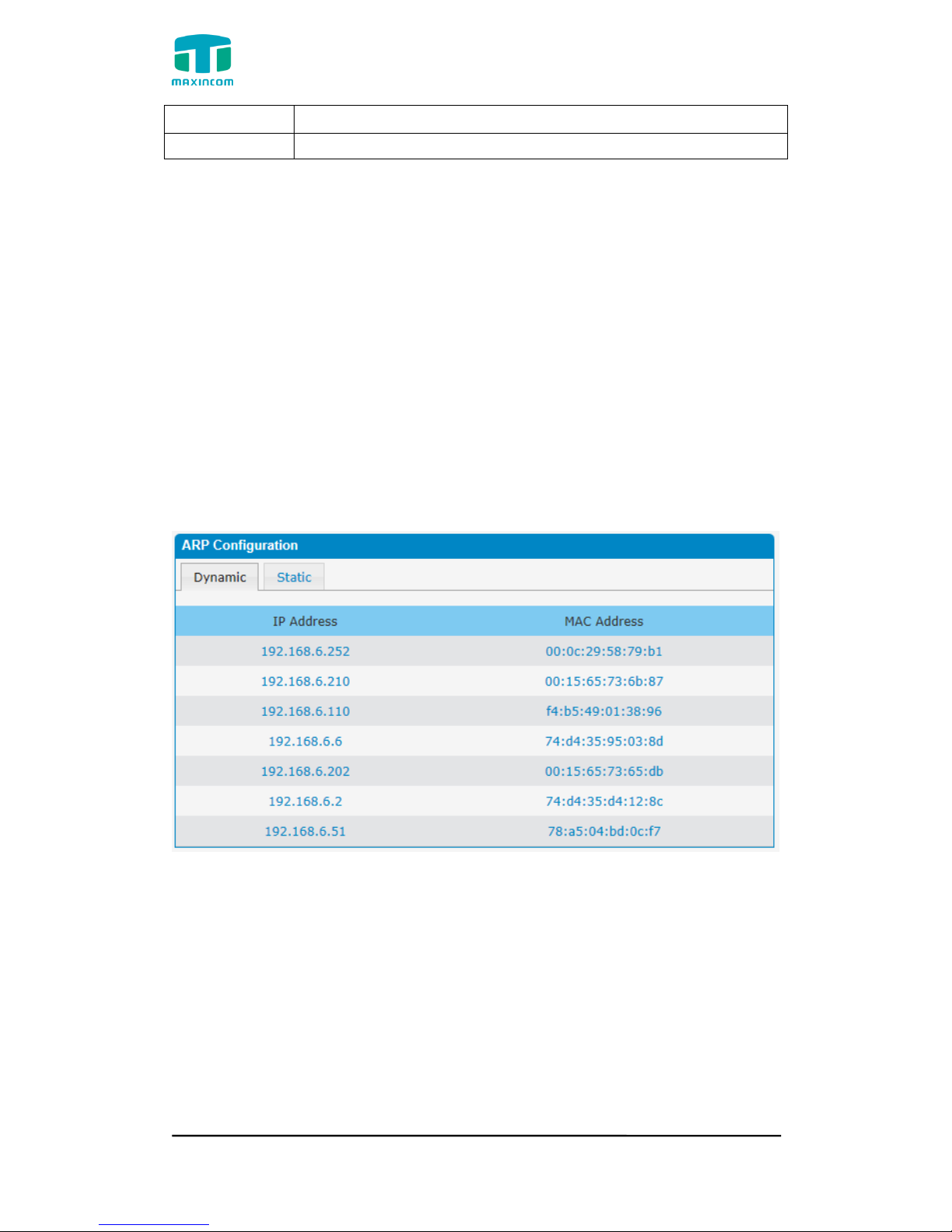
3.4.3 ARP Configuration
The ARP function is mainly used to query and add the map of IP and MAC.
There are static or dynamic ARP entries.
Like other routers, the gateway can automatically find the network device on
the same segment. But, sometimes you don't want to use this automatic
mapping, you'd rather have fixed (static) associations between an IP address
and a MAC address. Gateway provides you the ability to add static ARP entries
to:
● Protect your network against ARP spoofing
● Prevent network confusion as a result of misconfigured network device
Click “Dynamic ARP” to check ARP buffer
Figure 3.4.3a Dynamic ARP
MUC1004/2008/2016 Administrator guide
Http://www.maxincom.com 20 / 112
Figure 3.4.3 Add ARP
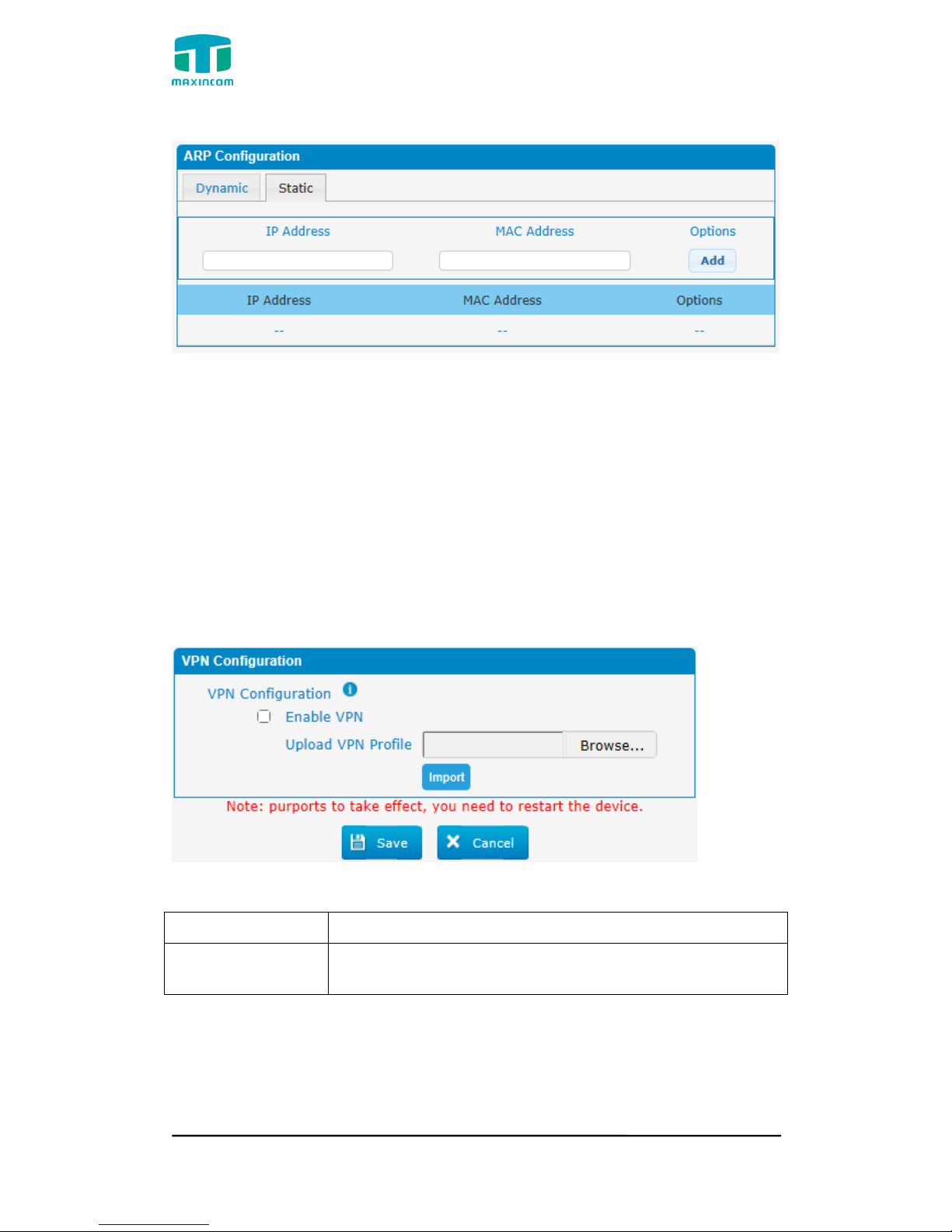
3.4.4 VPN Configuration
A Virtual Private Network (VPN) is a method of computer networking--typically
using the public internet--that allows users to privately share information
between remote locations, or between a remote location and a business' home
network. A VPN can provide secure information transport by authenticating
users, and encrypting data to prevent unauthorized persons from reading the
information transmitted. The VPN can be used to
send any kind of network traffic securely. PBX supports OpenVPN.
Figure 3.4.4 VPN Configuration
Table 3.4.4 Description of VPN Parameter
Parameters
Description
Import VPN
Configuration Files
Import configuration file of OpenVPN.
Notes:
1. Don't configure “user” and “group” in the “config” file. You can get the config
package from the OpenVPN provider.
2. PBX works as VPN client mode only.
MUC1004/2008/2016 Administrator guide
Http://www.maxincom.com 21 / 112
3.Upload file *.tar with *.conf in it.
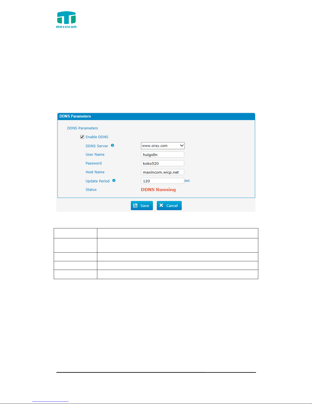
3.4.5 DDNS Server
DDNS(Dynamic DNS) is a method / protocol / network service that provides the
capability for a networked device, such as a router or computer system using
the Internet Protocol Suite, to notify a Domain Name System (DNS) name
server to change, in real time, the active DNS configuration of its configured
hostnames, addresses or other information.
Figure 3.4.5 DDNS Server
Table 3.4.5 Description of DDNS Server
Parameters
Description
DDNS Server
Select the DDNS server IP or domain name you sign up for
service.
User Name
User name the DDNS server provides you.
Password
User account‟s password.
Host Name
The domain name you have got from the DDNS server
Note: DDNS allows you to access your network using domain names instead of
IP address. The service manages changing IP address and updates your
domain information dynamically. You must sign up for service through
dyndns.org, freedns.afraid.org, www.no-ip.com, www.zoneedit.com
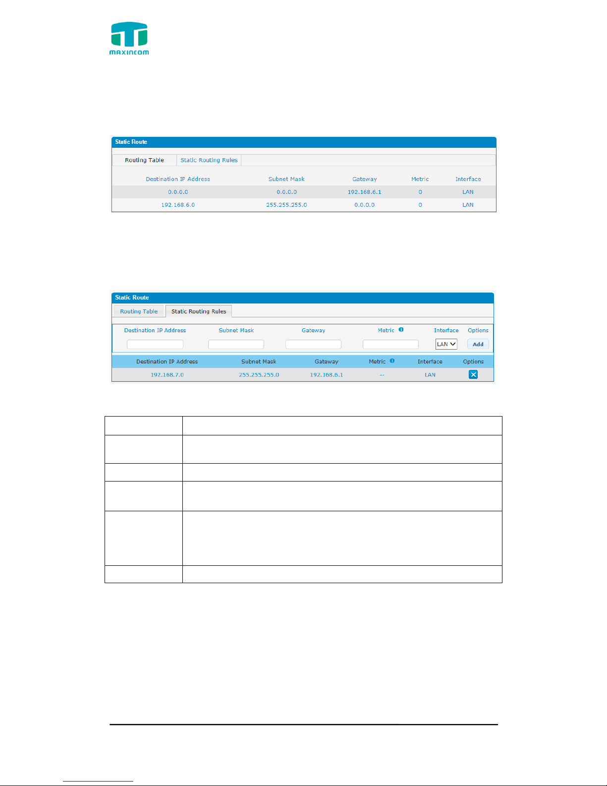
3.4.6 Static Route
PBX will have more than one internet connection in some situations but it has
only one default gateway. You will need to set some Static Route for PBX to
force it to go out through different gateway when access to different internet.
The default gateway priority of PBX from high to low is VPN/VLAN-> LAN port.
MUC1004/2008/2016 Administrator guide
Http://www.maxincom.com 22 / 112
1) Route Table
The current route rules of PBX.
Figure 3.4.6 Static Routing Table
2) Static Route Rules
You can add new static route rules here.
Figure 3.4.6a Static Routing Rules
Table 3.4.6 Description of Static Routing
Parameters
Description
Destination
IP Address
The destination network to be accessed to by PBX.
Subnet Mask
Specify the destination network portion.
Gateway
Define which gateway PBX will go through when access to the
destination network.
Metric
The cost of a route is calculated by using what are called
routing metric. Routing metrics are assigned to routes by
routing protocols to provide measurable statistic which can be
used to judge how useful (how low cost) a route is.
Interface
Define which internet port to go through.
MUC1004/2008/2016 Administrator guide
Http://www.maxincom.com 23 / 112
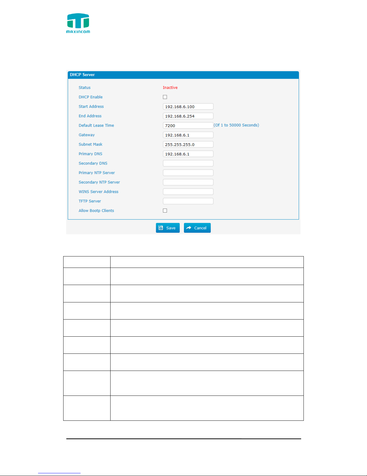
3.4.7 DHCP Server
Figure 3.4.7 DHCP Server
Table 3.4.7 Description of DHCP Server
Parameters
Description
Status
DHCP service status
DHCP Enable
Enable DHCP service
Start Address
Start IP of DHCP IP pool
End Address
End IP of DHCP IP pool
Default Lease
Time
Default lease time
Gateway
Gateway address
Subnet Mask
Address
Specify the destination network portion.
Primary DNS
Set the primary DNS Server for PBX.
MUC1004/2008/2016 Administrator guide
Http://www.maxincom.com 24 / 112
Secondary
DNS
Set the Secondary DNS Server for PBX.
Primary NTP
Server
Set the primary NTP Server
Secondary
NTP Server
Set the Secondary NTP Server
WINS Server
Address
Set the WINS Server Address
TFTP Server
Server
Set the TFTP Server
Allow Bootp
Clients
Allow bootp clients
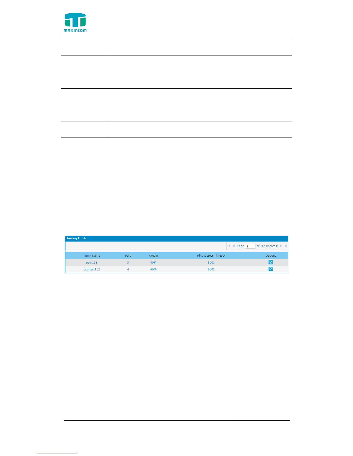
3.5 Trunks
3.5.1 Physical Trunks(PSTN and GSM Trunks)
The public switched telephone network (PSTN) is the network of the world's
public circuit-switched telephone networks.
Figure 3.5.1 Analog Trunks
MUC1004/2008/2016 Administrator guide
Http://www.maxincom.com 25 / 112
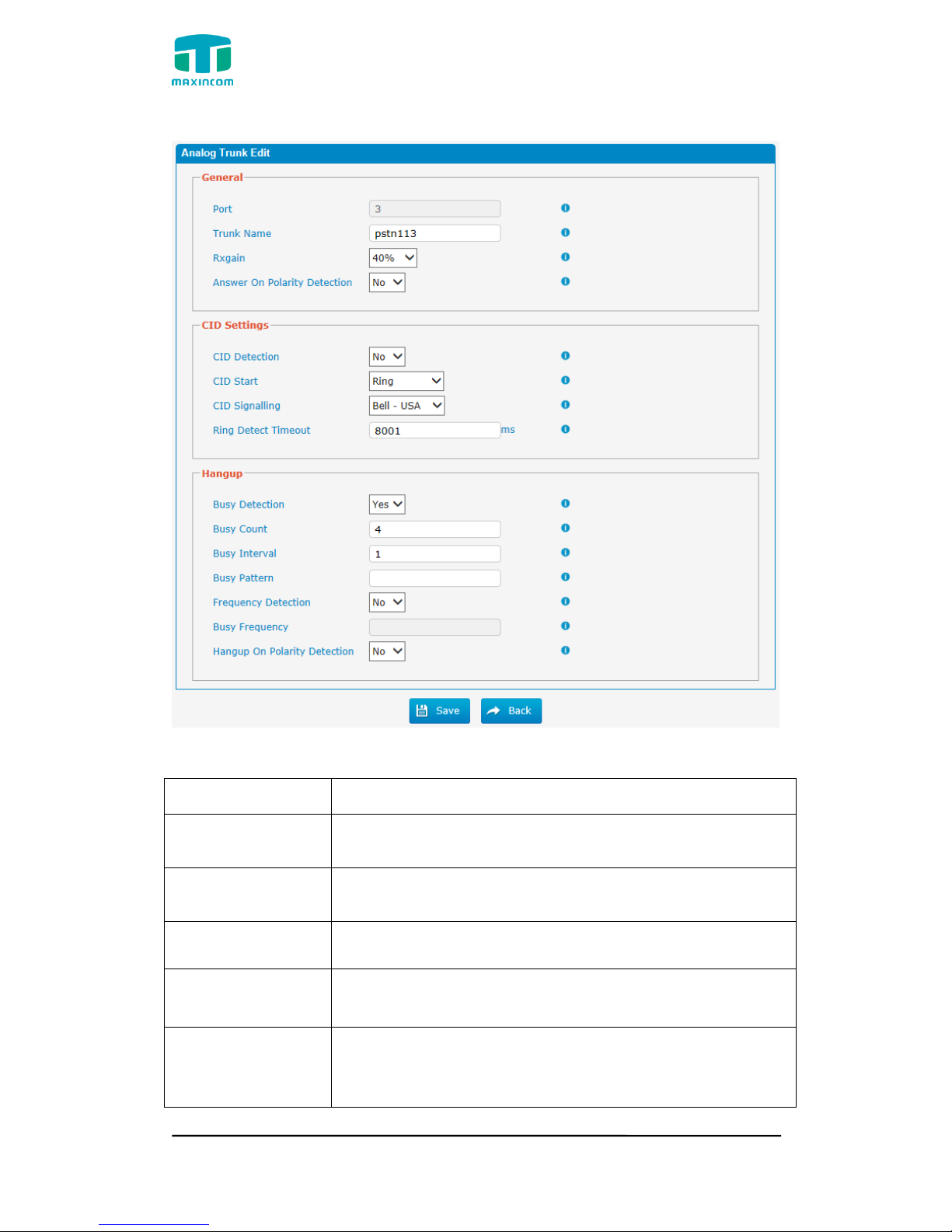
Figure 3.5.1a Analog Trunks Edit
Table 3.5.1 Description of Analog Trunk
Parameters
Description
Trunk Name
A unique label used to identify this trunk when listed in
outbound rules, incoming rules, etc.E.g. “pstn113”.
Rxgain
Used to modify the volume level of this trunk. Normally,
this setting does not need to be changed.
Answer on Polarity
Detection
Use a polarity reversal to mark when a outgoing call is
answered by the remote party
CID Detection
For FXO trunks, this option forces PBX to look for Caller ID
on incoming calls.
CID Start
This option allows you to define the start of a Caller ID
signal:
Ring: Start when a ring is received (Caller ID Signaling:

MUC1004/2008/2016 Administrator guide
Http://www.maxincom.com 26 / 112
Bell_USA, DTMF).
Polarity: Start when a polarity reversal is started (Caller ID
Signaling: V23_UK, V23_JP,DTMF).
Before Ring: Start before a ring is received (Caller ID
Signaling: DTMF).
CID Signalling
This option defines the type of Caller ID signaling to use. It
can be set to one of the following:
Bell_USA: bell202 as used in the United States
v23_UK: suitable in the UK
v23_Japan: suitable in Japan
v23-Japan pure: suitable in Japan
DTMF: suitable in Denmark, Sweden, and Holland
Busy Detection
Busy Detection is used to detect far end hang-up or for
detecting a busy signal. Select “Yes” to turn this feature
on.
Budy Count
If Busy Detection is enabled, it is also possible to specify
how many busy tones to wait for before disconnecting the
call. The default is 4, but better results can be achieved if
set to 6 or even 8. Remember, the higher the number, the
more time will be required to release a channel. A higher
setting lowers the probability that you will encounter
random hang-ups.
Busy Interval
The busy detection interval
Busy Pattern
If Busy Detection is enabled, it is also possible to specify
the cadence of your busy signal.In many Countries, it is
500msec on, 500msec off. If a Busy Pattern is not
specified,The system will accept any regular sound-silence
pattern that repeats <Busy Count> times as a busy signal.
If you specify Busy Pattern, then the system will further
check the length of the tone and silence, which will further
reduce the chance of a false positive disconnection.
Frequency
Detection
Used for Frequency Detection (Enable detecting the busy
signal frequency or not).
Busy Frequency
If the Frequency Detection is enabled, you must specify
the local frequency.
Hangup Polarity
Reversal Detection
The call will be considered as “hang up” on a polarity
reversal.
MUC1004/2008/2016 Administrator guide
Http://www.maxincom.com 27 / 112
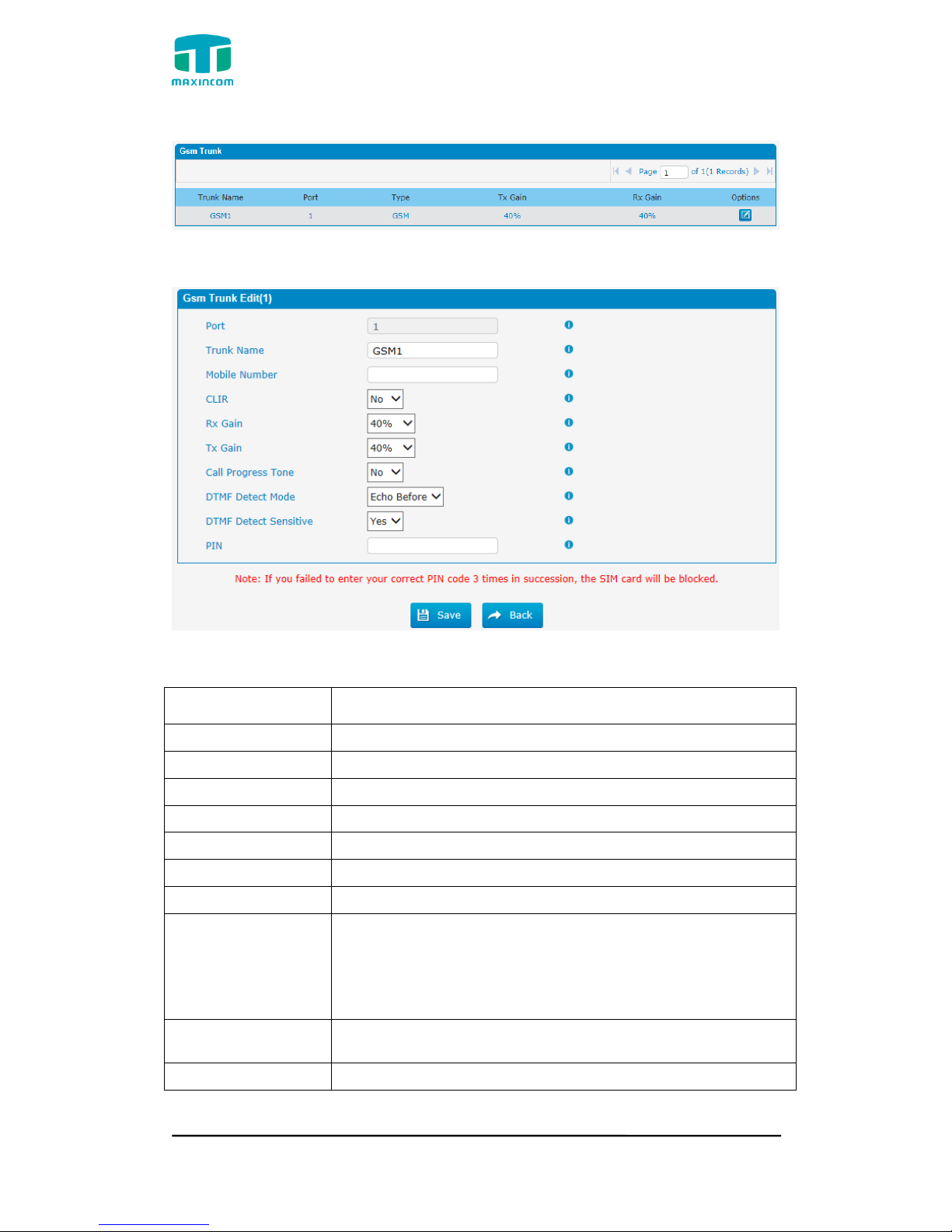
Figure 3.5.1b GSM Trunks
Figure 3.5.1c GSM Trunks Edit
Table 3.5.1c Description of GSM Trunk
Parameters
Description
Port
A port for this trunk.
Trunk Name
A name for this trunk.
Mobile Number
Mobile number for this trunk.
CLIR
Calling Line Identification Restriction.
Rx Gain
The receive volume.
Tx Gain
The transfer volume.
Call Progress Tone
A ringback for this trunk.
DTMF Detect Mode
Set default dtmfmode for detect DTMF.
Default: Echo Before
Echo Before: Detect DTMF before echocan.
Echo After: Detect DTMF after echocan.
DTMF Detect
Sensitive
DTMF detect sensitive.
PIN
The PIN is normally associated with the SIM card.
MUC1004/2008/2016 Administrator guide
Http://www.maxincom.com 28 / 112
3.5.2 IP Trunk (Peer to Peer Mode)
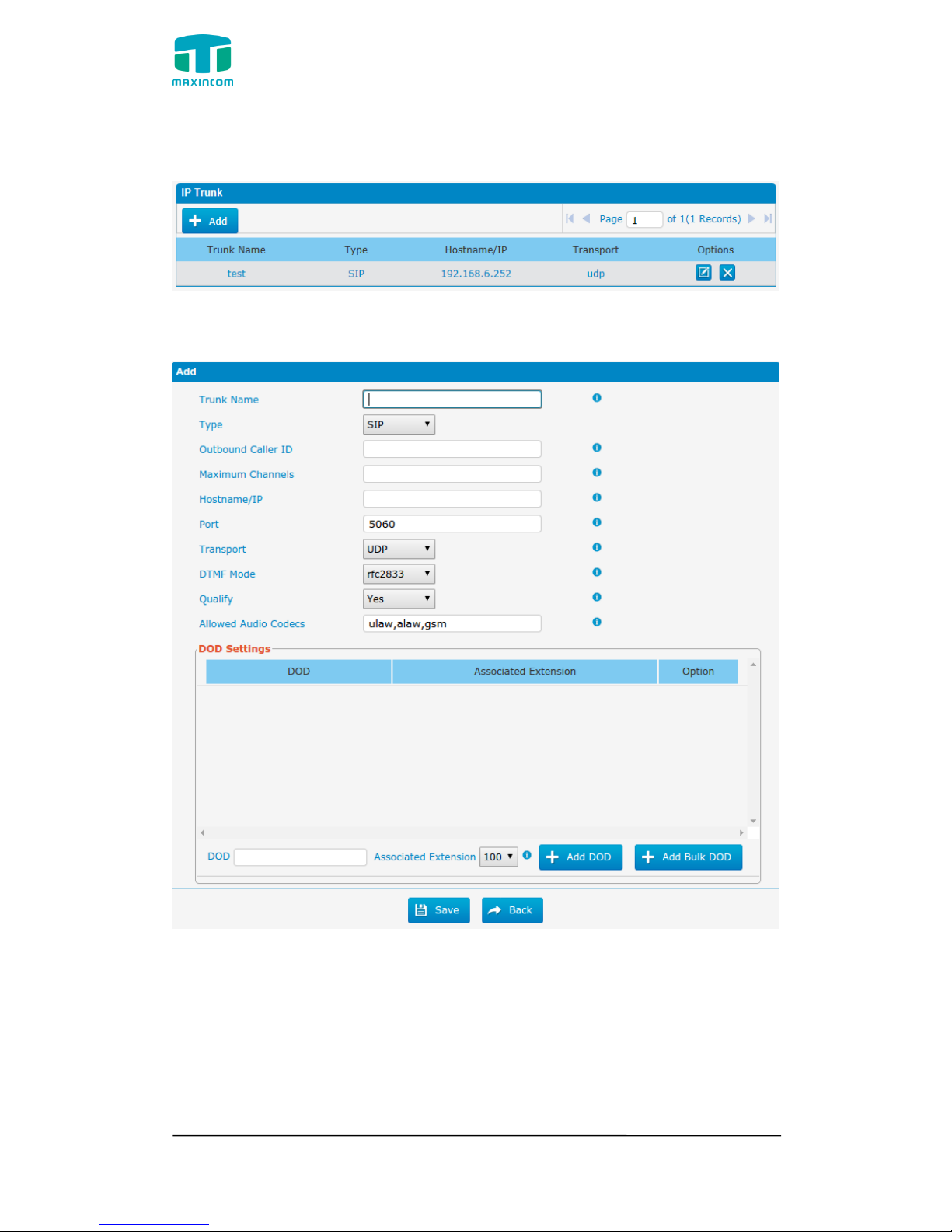
Figure 3.5.2 IP Trunk
Figure 3.5.2a Add IP Trunk
MUC1004/2008/2016 Administrator guide
Http://www.maxincom.com 29 / 112
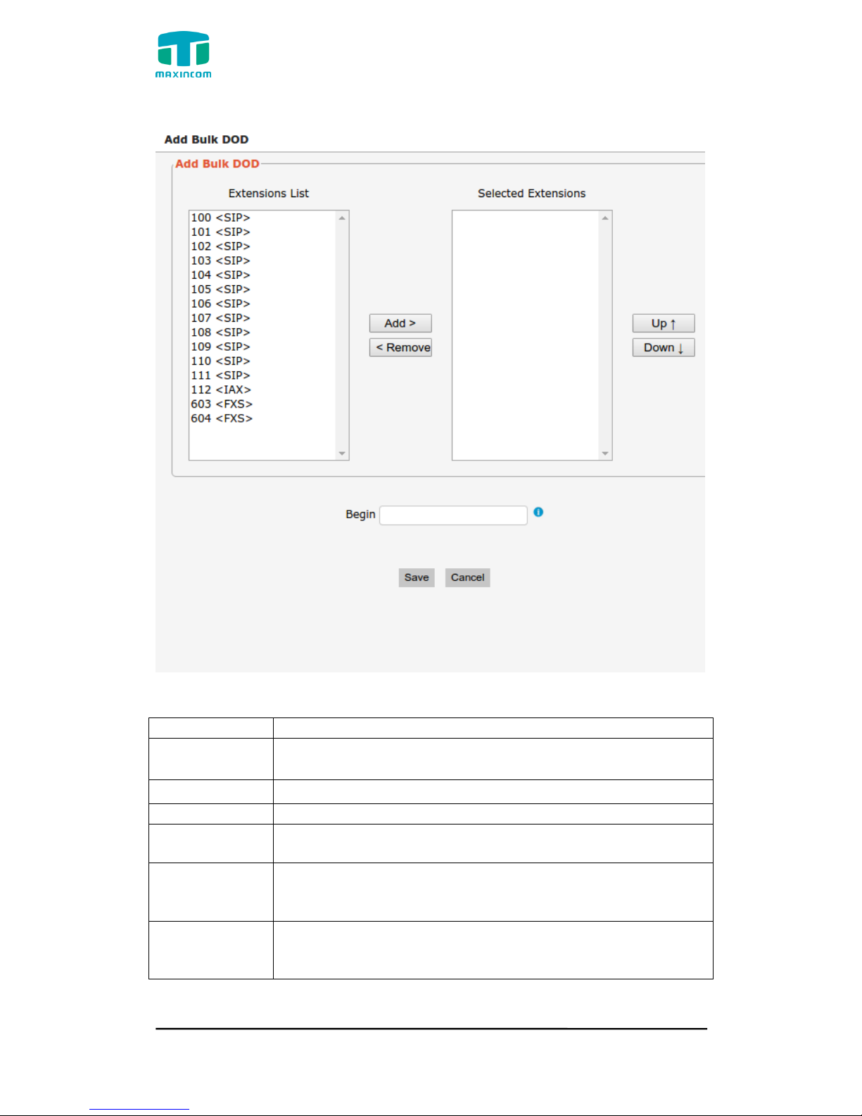
Figure 3.5.2b Add Bulk Dod
Table 3.5.2 Description of IP Trunk
Parameters
Description
IP Trunk
Add remote IP of Softswitch, SIP server which will send call
traffics to gateway.
Trunk Name
It describes the trunk for the ease of identification.
Type
Choose the type of this trunk, SIP or IAX
Outbound
Caller ID
Caller ID for calls placed on out this trunk
Hostname/IP
Address
Service provider‟s hostname or IP address,5060 is the
standard port number used by SIP protocol. Don‟t change
this part if it is not required.
Transport
This will be the transport method used by the SIP Trunk. This
method is given by the SIP trunk provider. The options are
UDP (default) or TCP or TLS.
MUC1004/2008/2016 Administrator guide
Http://www.maxincom.com 30 / 112
DTMF Mode
Set default mode for sending DTMF of this trunk. Default
setting: rfc2833, Info, Shortinfo,Inband, Auto
Qualify
Send checking alive packets to the SIP provider. when it‟s
disabled, PBX will ignore the reachability and the status of
this account will be unmonitored.
Allow codecs
ulaw,alaw,gsm
DOD
Settintings
Add dod number to associated extension.
Add Bulk DOD
Add bulk dod number to associated extensions which begin
with Begin number
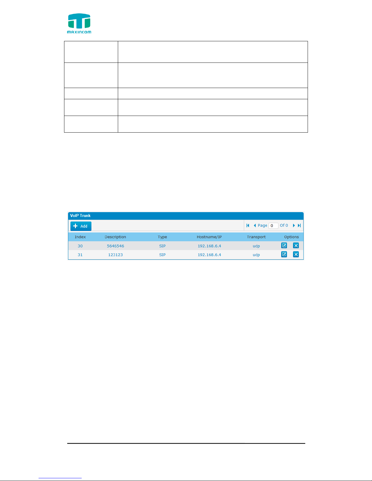
3.5.3 VoIP Trunk
In this page, we can configure VoIP trunk (SIP/ IAX) you have got from
provider with the authorization name and password.
Figure 3.5.3 VoIP Trunk
 Loading...