


Wireless
Dual Band Amplifier
In-Vehicle
MAXIMUM
SIGNAL
USER GUIDE
TM

PAGE 1
.....................................................................................2
......................................................................2
.......................................................................4
........................................4
.................................................5
.................................................5
.............................6
...................................................7
............................................8
............................................8
. ............................................................8
Warnings
Package Contents
Quick Start Guide
Choosing a location for your device
Installing the Exterior Antenna
Installing the Interior Antenna
Powering your Traveler Wireless Amplifier
Understanding the LED lights
Antenna options and accessories
Wireless Amplifier specifications
Guarantee and warranty
Before starting the initial installation process, you should
read the entire instruction manual and understand the importance of following the recommended installation instructions.
There are important safety and operating information guidelines to insure proper performance of your device. Failure to
do so could be hazardous and result in damage to your
device, voiding your warranty.
After reading the entire instruction manual and before actually installing, Maximum Signal, Inc.
TM
strongly recommends that you visualize where each component will be
placed. This will avoid unnecessary problems with your
installation (i.e. nail holes, reinstalling a component,
re-wiring etc), and create a pleasant and successful experience with this device.
*NOTE: All Maximum Signal, Inc.
TM
devices are manufactured to
provide you with a pleasant experience, by following the simple instructions within in this manual you will be assured not to cause adverse
effects on any cellular network
.
Contents

PAGE 2PAGE 2
You are cautioned that changes or modifications not expressly
approved by Maximum Signal, Inc.™ could void your
authority to operate the equipment.
This device complies with Part 15 of the FCC Rules. Operation
is subject to the following two conditions:
(1) this device may not cause harmful interference and (2) this
device must accept any interference received, including interference that may cause undesired operation.
FCC regulations require that antennas connected to this device
can not exceed the maximum allowable dbi rating regardless of
whether the antennas are installed inside or outside a structure. Doing so will violate Maximum Signal, Inc.™ and Federal
guidelines and regulations which the user will be liable for , and
will result in your warranty being voided.
The Exterior antenna with this device may not have gain that
exceeds 10 dBi and may not be located within thirty-nine (39”)
inches of any person.
The Internal antenna may not gain exceeds 10 dBi and may not
be located within eight (8”) inches of any person.
Do not plug the Wireless Amplifier into an AC power supply
until all antennas are installed and connected correctly.
The use of any power supply other than the one supplied by
Maximum Signal, Inc.™ may damage your device and will
void your warranty.
Verify the electrical outlet you have chosen can support this
device.
Select a location to install this device, making sure there is
adequate ventilation and no moisture present.
Always check with your local governing body or homeowner
association for rules and regulation regarding the installation of
the Exterior antenna.
!
!
!
!
!
!
!
!
!
!
Warnings

*Typical Installation Example
PAGE 4
Alcohol
Prep Pad
Tampon de preparation a l’alchool
Mit Alkohol getrankter Lappen
Cuscinetto preparatorio all’alcol
Voorbereidingsdoekje met alcohol
Compresa con alch
For Professional and Hospital Use
M
i
c
r
o
U
S
B
P
o
w
e
r
A
d
a
p
t
e
r
R
e
a
r
G
l
a
s
s
A
n
t
e
n
n
a
C
a
b
l
e
G
l
a
s
s
C
l
e
a
n
i
n
g
P
a
d
R
e
a
r
G
l
a
s
s
A
t
t
a
c
h
m
e
n
t
-
I
n
t
e
r
i
o
r
R
e
a
r
A
n
t
e
n
n
a
M
a
s
t
R
e
a
r
G
l
a
s
s
A
t
t
a
c
h
m
e
n
t
-
E
x
t
e
r
i
o
r
F
r
o
n
t
A
r
e
a
P
a
t
c
h
A
n
t
e
n
n
a
(C)
(B4)
(B3)
(B2)
(D) (B5) (B1)
Maximum Signal
Wireless Amplifier
Alcohol
Prep Pad
Tampon de preparation a l’alchool
Mit Alkohol getrankter Lappen
Cuscinetto preparatorio all’alcol
Voorbereidingsdoekje met alcohol
Compresa con alch
For Professional and Hospital Use
REF./Reorder No.B339
QuickStart
Guide
TM
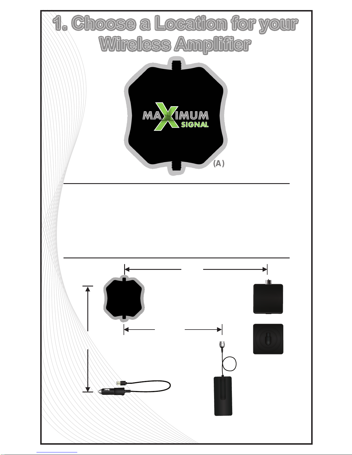
Select a suitable location for your Wireless Amplifier (A). There
are three cable lengths you should be aware of. The Wireless
Amplifier must be located within the cable lengths of the
supplied items.
1. Glass Antenna Cable- Exterior is 10ft long
2. The Front Patch Antenna Cable is 10ft long
3. The Power cable is 6ft long.
(A)
PAGE 5
6ft.
10ft.
(Max)
(Max)
10ft.
(Max)
1. Choose a Location for your
Wireless Amplifier
TM

PAGE 6
Remove the protective covering from the back of the Exterior
Glass Attachment and attach it to the outside of the rear
window.
NOTE: Make sure the antenna connector is facing up and the
Glass Mount Attachment is not placed over any defroster filaments. This
device utilizes antennas that requires a horizontal separation of a minimum
of Four (4ft.) feet and a minimum vertical separation of Four (4ft) feet. The
Exterior Glass Antenna MUST have a minimum of 180º degree line of sight.
with a minimum of Ten (10”) inches above any obstructions.The Exterior
Glass Antenna must be installed no further than Fifteen (15ft) feet of the
device. Extending the cable with a coupler and/or additional cable may
reduce the performance of the device. Exercise caution when attaching the
cable to the device or antenna making certain the center pin on the cable
does not bend.
Using the supplied Alcohol Glass cleaning pad, thoroughly,
wipe both the inside/outside of the Glass surface where the
antenna will be mounted.
Prior to attaching the Rear Glass Attachment - Interior, align
the interior attachment exactly the same as the previously
installed exterior window antenna attachment. Remove the
protective covering from the back of the Interior Glass Attachment and attach it to the window . *
NOTE: Make sure cable connector
is facing up and Glass Mount Attachment is not placed over any defroster
filaments.
Run the Rear Glass Antenna Cable to the device. Note: Never
use staples or any other fasteners to secure the cable, and exercise extreme
caution not to puncture the cable lining as it may cause the device to
cease
functioning properly.
Hand tighten the Exterior Glass Antenna Cable to the device at
the connector labeled EXT/ANT. *
Note: Over tightening the cable
connector to the device may damage the device thus voiding your warranty.
INSIDE THE WINDOW
OUTSIDE THE WINDOW
X
2. Installing the Rear Glass
Antenna
PAGE 7
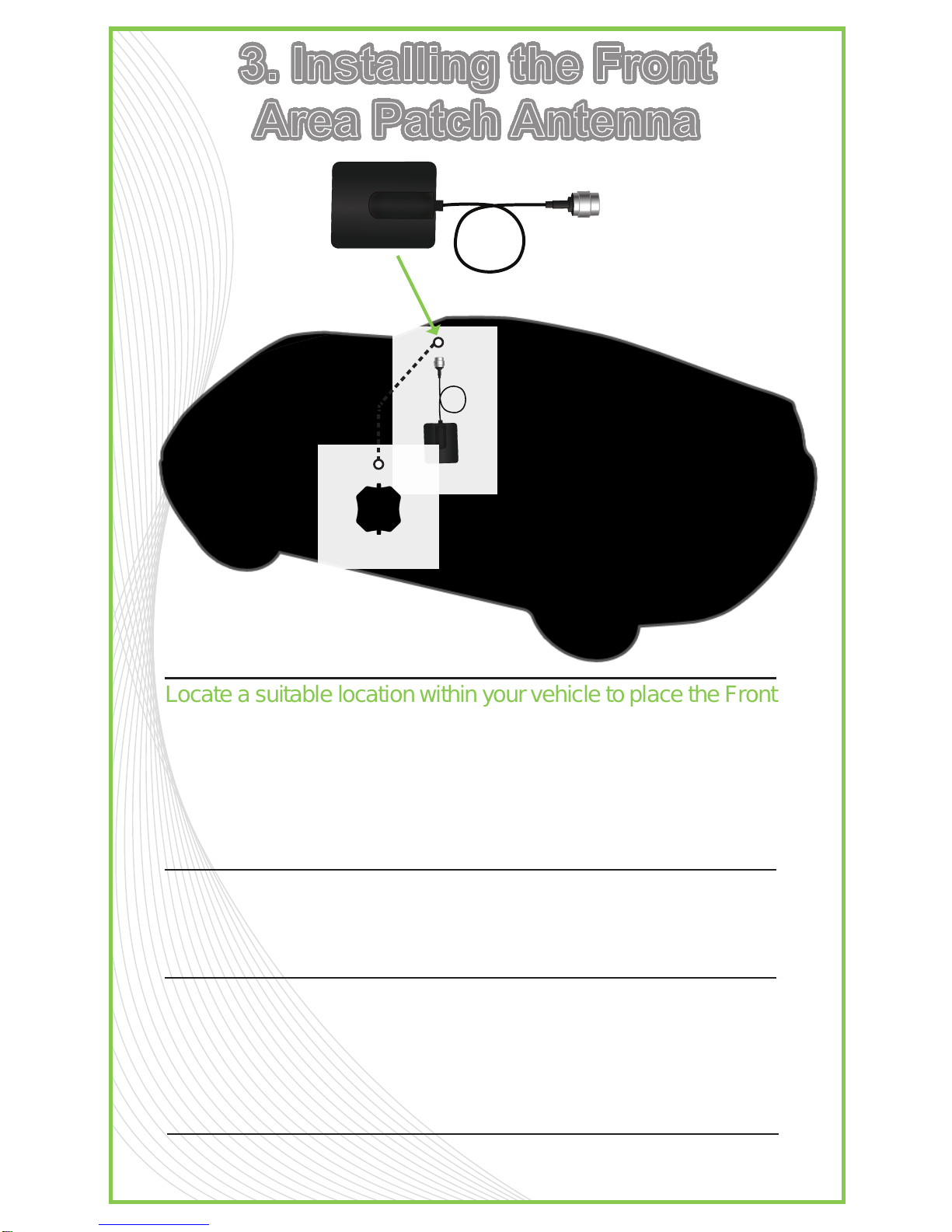
Locate a suitable location within your vehicle to place the Front
Area Patch Antenna.
Note: The outside plastic covering the Front Area
Patch Antenna MUST point towards the interior of your vehicle. This device
utilizes antennas that require a horizontal separation of a minimum of Four
(4ft.) feet and a minimum vertical separation of Four (4ft) feet. The Interior
Glass Antenna must be installed no further than Twelve (12ft) feet from the
device. Extending the cable with a coupler and/or additional cable may
reduce the performance of the device.
Run the Front Area Patch Antenna Cable to the device.
Note: Never use staples or any other fasteners to secure the cable. Exercise
extreme caution not to puncture the cable lining as it may cause the device
to cease functioning properly.
Hand tighten the Front Area Patch Antenna cable to the
device at the connector labeled DEVICE INT ANT. *
NOTE:
Over tightening the connector on the cable to the device may damage the
device thus voiding your warranty. Exercise caution when attaching the
cable to the device or antenna making certain the center pin on the cable
does not bend.
(C)
3. Installing the Front
Area Patch Antenna
PAGE 8
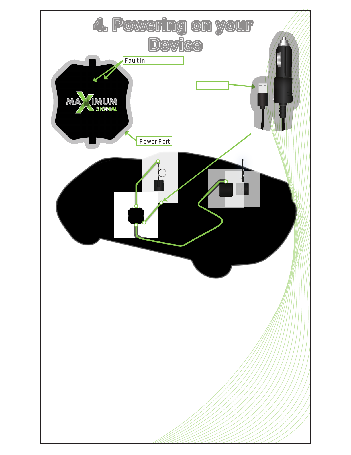
Plug the Micro USB connector power into the device labeled
“power”.
Plug the power supply cable into your vehicle power source.
The blue LED light indicates your Maximum Signal
™ Wire-
less Amplifier has power and is operational. If you have a RED
device fault indicator light illuminated on the top of your device,
your antennas are likely incorrectly placed. In the unlikely
situation that this error occurs, then unplug your power supply
cable immediately, and increase the separation between the
exterior and interior antennas. Then re-connect the power
supply cable into your vehicle power source. The blue LED
light indicates your Maximum Signal
™ Wireless Amplifier has
power and is operational.
Power Port
Fault Indicator Lights
Micro USB
BAND BAND POWER
4. Powering on your
Device
TM

PAGE 9
1-Year Warranty
Maximum Signal, Inc.™ warrants for a period of one (1) year this product is
free from any defects in material or workmanship. If a defect is found by
Maximum Signal, Inc.™, Maximum Signal, Inc.™ agrees to repair or
replace the product at its own discretion EXCLUDING ALL SHIPPING
CHARGES. This product must have been registered with Maximum Signal,
Inc.™ within 30-days of purchase and you are the original owner. To return
a product, an RMA number must be obtained by contacting customer
support. Maximum Signal, Inc.™ will not accept returns unless all parts,
packaging, and accessories along with dated proof of purchase with original
receipt (copies not permitted) from where you purchased your product must
be included with your return. Failure to return all product, parts, packaging,
and accessories will result in only the product returned being replaced. If the
product has been modified, abused or tampered with in any manner, Maxi-
mum Signal, Inc.™ will consider the warranty void. Any use of non Maxi-
mum Signal, Inc.™ antennas, cables or other accessories will void your
warranty.
Disclaimer: All information included in this document by Maximum Signal,
Inc.™ is believed to be complete and accurate. Maximum Signal, Inc.™
assumes no responsibility or liability for any business or personal losses
arising from its use, or for any infringements of patents or other rights of third
parties that may result from its use.
Copyright © 2010 Maximum Signal, Inc.™ All rights reserved.
For Additional Technical Support Visit
MaximumSignal.info
FCC ID:
XZZ-WB-198
IC
Model
Antenna connectors
Antenna impedance
Dimensions
Weight
Frequency
Passband Gain
Dual-Band Wireless
800/1900 MHz Specifications
9176A-SPTR
TNC Female
50 ohms
3.5 x 3.5 x 1 inch (8.8 x 8.8 x 2.5 cm)
0.3 lbs (0.14 kg)
824-894 MHz / 1850-1990 MHz
45 dB
In-Vehicle Wireless
Technical Specifications

Amplifiers
Antennas Accessories
Copyright © 2010 Maximum Signal, Inc. All rights reserved.
Visit www.MAXIMUMSIGNAL.info
 Loading...