


Maximum Signal 5K User Manual
1
MA IM
SIGN A L
UM

2
MA IM
SIGN A L
UM
Contents . . . . . . . . . . . . . . . . . . . . . . . . . . . . . . . . . . . . . . . . . . . . . . . . . . . . . . . . . . . . . . . . . . . . . . . . . . . . 2
warnings . . . . . . . . . . . . . . . . . . . . . . . . . . . . . . . . . . . . . . . . . . . . . . . . . . . . . . . . . . . . . . . . . . . . . . . . . . . . 3
warranty . . . . . . . . . . . . . . . . . . . . . . . . . . . . . . . . . . . . . . . . . . . . . . . . . . . . . . . . . . . . . . . . . . . . . . . . . . . . 9
technical specifications . . . . . . . . . . . . . . . . . . . . . . . . . . . . . . . . . . . . . . . . . . . . . . . . . . . . . . . . . . . . .10
installing the exterior antenna . . . . . . . . . . . . . . . . . . . . . . . . . . . . . . . . . . . . . . . . . . . . . . . . . . . . . . 6
installing the interior antenna . . . . . . . . . . . . . . . . . . . . . . . . . . . . . . . . . . . . . . . . . . . . . . . . . . . . . . . 7
Powering your MAX -AMP 5K 5 Band
Wireless 4G/LTE Cellular Amplifier . . . . . . . . . . . . . . . . . . . . . . . . . . . . . . . . . . . . . . . . . . . . . . . . . . . 8
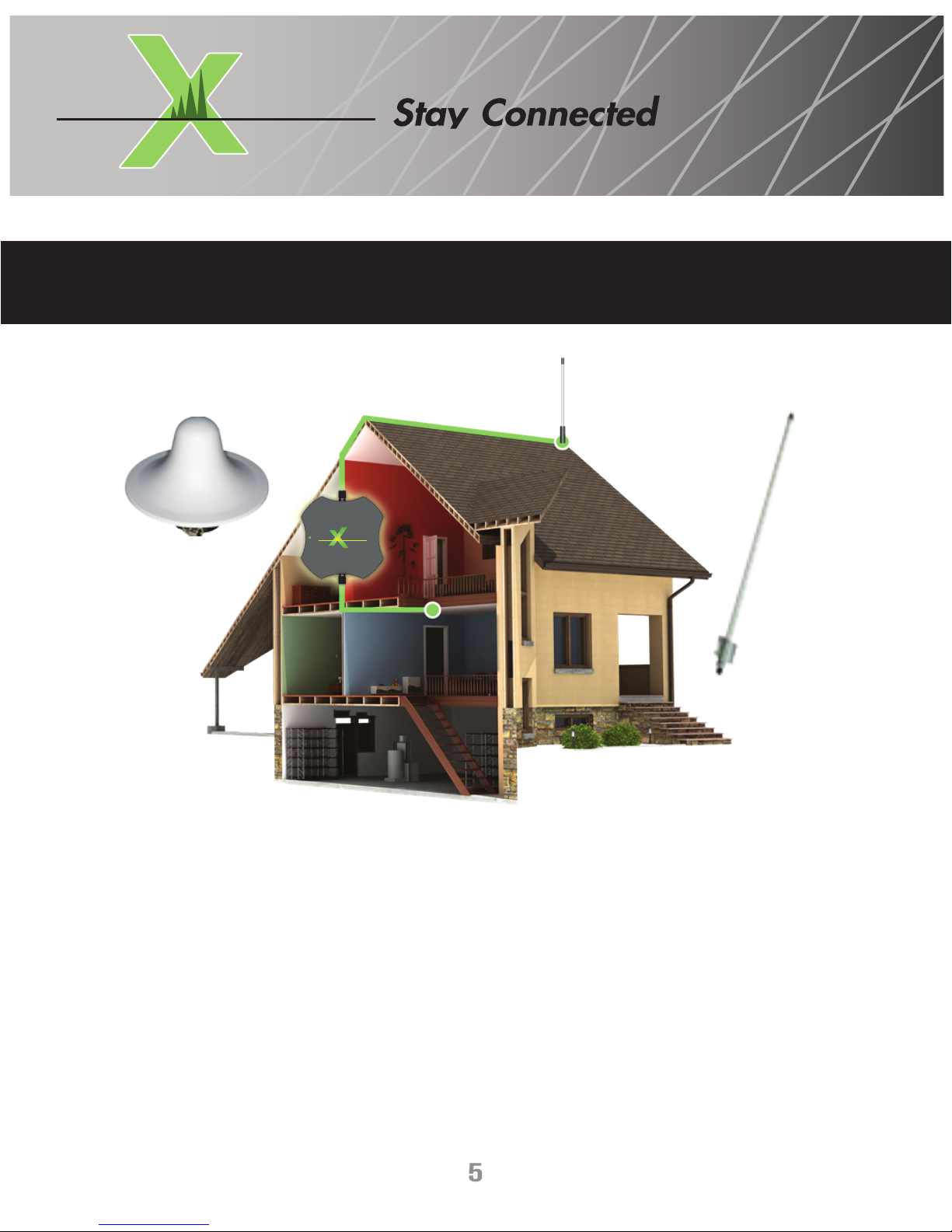
choosing a location for your device . . . . . . . . . . . . . . . . . . . . . . . . . . . . . . . . . . . . . . . . . . . . . . . . . . . 5
installation overview . . . . . . . . . . . . . . . . . . . . . . . . . . . . . . . . . . . . . . . . . . . . . . . . . . . . . . . . . . . . . . . 4
TABLE OF CONTENTS

WARNINGS
3
MA IM
SIGN A L
UM
BEFORE USE, you MUST REGISTER THIS DEVICE with your wireless provider and have your provider’s consent. Most wireless
providers consent to the use of signal boosters. Some providers may not consent to the use of this device on their
network. If you are unsure, contact your provider.
This device complies with Part 15 of the FCC Rules. Operation is subject to the following conditions:
1. This device may not cause harmful interference.
2. This device must accept any interference received, including interference that may cause undesired operation.
WARNING: E911 location information may not be provided or may be inaccurate for calls served by using this device.
You are cautioned that changes or modifications expressly approved by the FCC will void your authority to operate this
equipment.
You MUST operate this device with approved antennas and cables as specified by the manufacturer. No Antenna can be used
within eight inches (8”) of any person.
You MUST cease operating this device immediately if requested by the FCC or a licensed wireless service provider.
FCC regulations require that only antennas connected to this device during FCC testing used and cannot exceed a certaindBi
rating.
Any use of a higher dBi rated antenna is prohibited and will violate FCC regulations. The user must cease to the use of this
amplifier and may be subject to FCC penalties.
Do not unplug wireless amplifier into any power supply until all antennas are connected to the amplifier.
The use of any power supply other than the one supplied by Maximum Signal LLC may damage your amplifier and will void
your warranty.
this is a consumer device

INSTALLATION OVERVIEW
4
MA IM
SIGN A L
UM
Before starting the initial installation process, you need to read the entire instruction manual and follow the required installation
instructions. There are important safety and operating information guidelines to insure proper performance of your device. Failure to
do so could be hazardous to you and the network you are using. This will result in damage to your device, and void your warranty.
After reading the entire instruction manual and before actually installing, your Maximum Signal Max-Amp Wireless 5K 4G/LTE cellular
amplifier, we strongly recommend that you look where each component will be placed. This should avoid unnecessary problems with
your installation (i.e. reinstalling a component, re-wiring etc.), and will result in a pleasant and successful experience with this device.
All Maximum Signal LLC devices are manufactured to provide you with a pleasant experience. By following the simple instructions within
in this manual you will be assured not to cause adverse effects on any cellular network.
By following the simple instructions within this manual, you will be assured not to cause adverse effects on any cellular network.
typical installation example:
MA IM
SIGNA L
UM
MAX-AMP 5K
POWER
5
MA IM
SIGN A L
UM
MA IM
SIGNA L
UM
MAX-AMP 5K
POWER
materials needed : Amp, Power cord, and cables
Before installing, select a suitable location for your new MAX-AMP 5K 5 Band Wireless 4G/LTE cellular amplifier there are three cable
lengths you should be aware of. Select a location to install the amplifier making sure there is adequate ventilation and no moisture is
present.
The wireless amplifier must be located within the cable lengths of the supplied items.
1. (1) Omni directional internal ceiling antenna
2. (1) Omni directional external antenna
3. (2) 35ft cable is feet long
4. (1) The power cable is 4 feet long
CAUTION: Extending cable lengths with any other cable except the one supplied by Maximum Signal LLC or using a non Maximum Signal
LLC antennas will violate FCC regulations and will result in the voiding of your warranty.
choose a location
for your wireless amplifier

6
MA IM
SIGN A L
UM
MA IM
SIGNA L
UM
MAX-AMP 5K
POWER
installing
external omni directional antenna
The MAX-AMP 5K 5 Band Wireless 4G/LTE cellular amplifier utilizes antennas that require a horizontal separation of a minimum of Twenty (20ft.) feet and a minimum vertical
separation of six (6) feet.
The external Omni directional antenna must be installed no further than thirty-five (35ft) feet from the MAX-AMP 5K 5 Band Wireless 4G/LTE cellular amplifier.
Extending the cable with a coupler and/or additional cable may reduce the performance of the MAX-AMP 5K 5 Band Wireless 4G/LTE cellular amplifier.
The external Omni directional antenna MUST have a minimum of 180º degree line of sight with a minimum of Eighteen (18”) inches above any obstructions.
1. Select location on the top of your roof where the best signal is found to place the external Omni directional antenna for maximum performance.
2. Before final installation of the external Omni directional antenna make sure the external Omni directional antenna cable can reach your MAX-AMP 5K 5 Band Wireless 4G/LTE
cellular amplifier.
3. Attach the external Omni directional antenna securely to the roof in a vertical position using the supplied mounting bracket. Run the cable from the external Omni directional
antenna to the MAX-AMP 5K 5 Band Wireless 4G/LTE cellular amplifier.
4. Hand tighten the external Omni directional antenna cable to the MAX-AMP 5K 5 Band Wireless 4G/LTE cellular amplifier at the antenna connector labeled EXT/ANT. Over
tightening the cable connector to the amplifier may damage the MAX-AMP 5K 5 Band Wireless 4G/LTE cellular amplifier.
5. Never use staples or any other fasteners to secure the cable, and exercise extreme caution not to puncture the cable lining as it may cause the device to cease functioning
properly.

7
MA IM
SIGN A L
UM
MA IM
SIGNA L
UM
MAX-AMP 5K
POWER
installing
internal omni directional antenna
The MAX-AMP 5K 5 Band Wireless 4G/LTE cellular amplifier utilizes antennas that require a horizontal separation of a minimum of Twenty (20) feet and a minimum
vertical separation of six (6) feet.
The internal Omni directional ceiling antenna must be installed no further than thirty-five (35) feet from the MAX-AMP 5K 5 Band Wireless 4G/LTE cellular amplifier.
Extending the cable with a coupler and/or additional cable may reduce the performance of the MAX-AMP 5K 5 Band Wireless 4G/LTE cellular amplifier.
1 Select a central location on the ceiling of the structure to- wards the center of the structure for placement of the internal ceiling antenna. The antenna must
be facing downward. Doing so will result in maximum coverage of your structure.
2 Before final installation of the internal Omni directional ceiling antenna make sure the internal Omni directional ceiling antenna cable can reach your MAX-AMP
5K 5 Band Wireless 4G/LTE cellular amplifier.
3 Securely attach the antenna to the ceiling. Make sure to anchor the antenna securely to the ceiling, with the small end pointing down. Run the internal ceiling
Omni directional antenna cable to the MAX-AMP 5K 5 Band Wireless 4G/ LTE cellular amplifier. Never use staples or any other fasteners to secure the cable, and
exercise extreme caution not to puncture the cable lining as it may cause the MAX-AMP 5K 5 Band Wireless 4G/LTE cellular amplifier to cease functioning properly.
4 Hand tighten the internal ceiling Omni directional antenna cable to the MAX-AMP 5K 5 Band Wireless 4G/LTE cellular amplifier at the connector labeled INT-ANT.
Over tightening the cable connector to the amplifier may damage the MAX-AMP 5K 5 Band Wireless 4G/LTE cellular amplifier, thus voiding your warranty.

8
MA IM
SIGN A L
UM
powering
on your device
MA IM
SIGN A L
UM
MAX-AMP 5K
POWER
1 Plug the Mini USB power adapter into the MAX-AMP 5K Wireless 4G/LTE cellular amplifier at the spot labeled “PWR”.
2 Plug the power adapter into a proper power receptacle.
3 The green LED light indicates your MAX-AMP 5K 5 Band Wireless 4G/LTE cellular amplifier has power and is operational.
4 If you have a RED fault indicator light illuminated on your MAX-AMP 5K 5 Band Wireless 4G/LTE cellular amplifier, your antennas are
not located properly. If this occurs, then unplug your power supply cable to the MAX-AMP 5K Wireless 4G/LTE cellular amplifier
immediately, and increase the separation between the external and internal antennas.
5 Then reconnect the power supply cable into your vehicle power receptacle and switch on power switch. The green LED lights indicate
your MAX-AMP 5K 5 Band Wireless 4G/LTE cellular amplifier has power and is operational.
6 If a RED fault indicator light illuminated on your MAX-AMP 5K 5 Band Wireless 4G/LTE cellular amplifier again repeat increasing your
antennas until a green light appears constant.
power adapter
mini usb
power fault
light

WARranty
9
MA IM
SIGN A L
UM
Maximum Signal LLC warrants for a period of one (1) year this product is free from any defects in material or
workmanship. If Maximum Signal LLC finds a defect Maximum Signal LLC agrees to repair or replace the product
at its own discretion.
EXCLUDING ALL SHIPPING CHARGES. The original owner must have registered this product must have been registered
with Maximum Signal LLC within 30 days of purchase.
To return a product, an RMA number must be obtained by contacting customer support. Maximum Signal LLC will
not accept returns unless all parts, packaging, accessories and the original receipt (copies not accepted) from
where you purchased your product are included. Failure to comply with return procedures will result in the
return being rejected.
If the product has been modified, abused or tampered with, the warranty is voided. Any use of non Maximum
Signal LLC antennas, cables or other accessories will void your warranty.
Disclaimer: All information included in this document by Maximum Signal LLC is believed to be complete and
accurate. Maximum Signal LLC assumes no responsibility or liability for any business or personal losses arising
from its use.
Copyright © 2015 Maximum Signal LLC. All rights reserved.
For additional Technical Support visit MaximumSignal.info

technical specifications
10
MA IM
SIGN A L
UM
model: max amp mobile
antenna connectors:
antenna impedance:
dimensions:
idle current draw:
weight (amp only):
full power current draw:
ac power requirements:
dc power requirements:
frequencies:
pass-band gain:
rf input and output impedance:
rf input and output vswr:
rf output:
acp (adjacent channel power):
noise figure:
isolation:
bleed through rejection uplink downlink bands:
dynamic range linearity:
receiver sensitivity:
40db. rf selectivity bandwidth:
idle current draw:
tnc female
50 ohms
5” x 5” x 1”
750mw
1lbs
2.0 amperage
110 - 240 vac 50-60 hz
(+)12 vdc
700 mhz, 850 mhz, 1700/2100 mhz, 1900 mhz
48.7db. max
50 ohms
1.76 db
29.2dbm. max
(-41.1) dbm min.
3.36db. max
121 db min.
80 db min.
100 db min.
(-114) dbm max
61 mhz
12vdc. -250 ma.
 Loading...