

Maximum Controls Max Megatron 1400, Max Megatron 1400HP, Max Megatron FAST, Max Megatron 2200 Installation Manual
Page 1
www.max.us.com
SAFETY SENSORS REQUIRED FOR UL 325 2016
1400HP
CONFORMS TO UL STD 325
UL CLASS - I, II, III, IV
CERTIFIED TO CAN/CSA STD
C22.2 NO. 247
Version 10
1400/2200/FAST
Residential / Commercial
Brushless DC
Swing Gate Operators
4009963
Made in USA
MAX MEGATRON
1400 / 1400HP / 2200 / FAST
Bi-Parting Gates ONLYSingle or Bi-Parting GatesSingle or Bi-Parting Gates Single or Bi-Parting Gates
Installation and Owners Manual
Page 2

Page 3

Table of contents
MAX Megatron Specifications
Important Safety Information
UL 325 Model Classifications
UL 325 Required Entrapment Protection
UL 325 Compliant Installation Requirements
Intended Use of Swing Gate Operator
Installation
Gate Operator Position
Recommended Gate Operator Layout
Layout and Arm Height of 1400/2200/FAST or 1400HP
Dual Gate Operators
Arm Position Options
Arm Connection to Gate
Optional Remote Power Supply Kit - MAX Magic Box
Compact Installation ONLY
Solar Optional
Entrapment Protection
In-Ground Loops
Install Warning Signs
Wiring operator
Gate Operator System Overview
Entrapment Protection Wiring
Input AC Power
Optional Remote Power Supply Kit - MAX Magic Box
Solar Power Connection - Optional
Secondary Operator to Matrix 1
Turn ON / OFF Operator Power
matrix 1
Matrix 1 Overview
Wiring Overview
Primary Gate - Open Left / Open Right
Close Timer
Selectable Gate Speed Control
Battery Back-Up Mode
Anti-Tailgate
Single Pass Anti-Tailgate
Radio Receiver
Radio Safety Pause
Gate in Motion Alarms
OBD Port Black Box
Maglock
Loop Detectors
In-Ground Loop Connection
ID Plug
Gate Tamper
UL Entrapment LEDs
Emergency Vehicle / Max Open Inputs
Gate Disable
Partial Open
UL Alarm / Shut-Off Alarm
Gate Status Monitoring
OPEN / STOP / CLOSE Connection
External Alarm Reset Button (Shut-Off Alarm)
CLOSING Photocell Connection
Gate Operators Communication LEDs
24V Power for Matrix 1
Battery in Use LED
Motor Motion LEDs
External OPEN/CLOSE Key Switch - Optional
10
10
11
12
12
13
14
15
15-16
17-18
19
20
21
22
23
24
25
26
26
26
26
27
27
28
28
28
28
29
29
29
30
30
30
30
31
31
32
32
32
32
32
33
33
33
33
34
2
2
3
3
4
5
6
7
8
9
Adjustments
Open and Close Limits
Release Handle Clamp
Reverse Sensor (ERD)
Maintenance
Qualified gate operator technician
End user/Home owner
MAX Megatron Primary Wiring Schematics
MAX Megatron Secondary Wiring Schematics
Manual Release
Electronic Gate Open / Close - Optional
Audible Alarm
Replacement Parts List
Warranty
Megatron options / unique features
Gate Tamper Feature
Gate Disable Feature
Event History Download
© 2015 Maximum Controls LLC.
All rights reserved. No part of this manual may be reproduced in any
means: graphics, electronics or mechanical, including photocopying
without the expressed written permission of the publisher. Materials
components and specifications are subject to change without notice.
35
36
37
38
38
39
40
41
42
42
43
44
45
46
46
1
Page 4
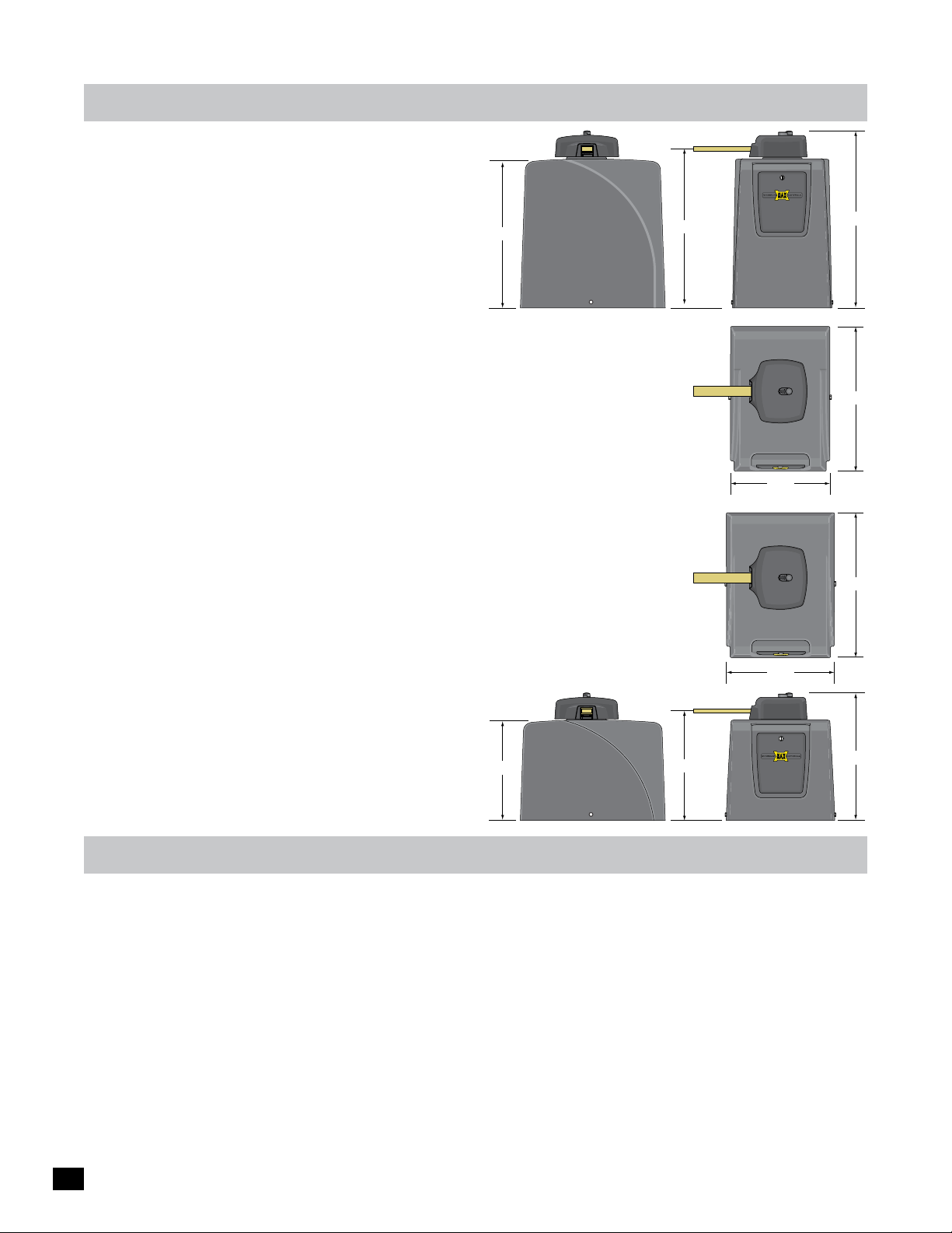
max megatron specifications
25.2”
UL 325 Class of Operation - Class I, II, III, IV
Gate Type - Vehicular Swing Gate
1400HP
(High Profile)
Max Gate Weight / Length:
- MAX Megatron 1400/1400HP - 1400lbs @ 15 ft or 1200 lbs @ 20 ft
- MAX Megatron 2200 - 2200lbs @ 15 ft or 1500 lbs @ 20 ft
- MAX Megatron FAST - 1600lbs @ 12 ft gate per operator
NOTE: The MAX Megatron FAST is ONLY available for installation on bi-parting gates (dual operators).
A single gate operator CANNOT be used.
90° Opening Time:
- MAX Megatron 1400/1400HP/2200 - 16 selectable speeds from approximately
11.5 sec to 20 sec depending on the weight and length of the gate.
- MAX Megatron FAST - 16 selectable speeds from approximately
6 sec to 14 sec depending on the weight and length of the dual gates.
Cycles per Hour AC Input Power - Continuous
Battery Back-Up Cycles (BC-7 Battery Module-7 Amp/Hr Batteries fully charged):
- Approximately 450 cycles
NOTE: The number of gate cycles using ONLY battery back-up power will vary depending on the
weight of the gate, the gate length, the operating condition of the gate hardware, temperature and
the amount of charge the batteries have at the beginning of the battery power only operation.
Input AC Power - Switchable: 115VAC or 230VAC single phase
Motor - 24VDC Brushless (equivalent to 1 HP AC motor)
Operating Temperature: -4°F to 158°F (-20°C to 70°C)
Entrapment Protection:
- UL 325 Type A Inherent (ERD sensor)
- Inputs for NORMALLY CLOSED (N.C.)
17”
UL 325 Type B1 (photo cell)
and Type B2 (sensing edge)
26.6”
18.5”
29.9”
1400HP
24.5”
1400HP
16.8”
24.5”
18.3”
21.3”
important safety information
WARNING – To reduce the risk of injury or death:
1. READ AND FOLLOW ALL INSTRUCTIONS.
2. Never let children operate or play with gate controls. Keep the remote control away from children.
3. Always keep people and objects away from the gate. NO ONE SHOULD CROSS THE PATH OF THE MOVING GATE.
4. Test the gate operator monthly. The gate MUST reverse on contact with a rigid object or stop when an object activates the
non-contact sensors. After adjusting the force or the limit of travel, retest the gate operator. Failure to adjust and retest the
gate operator properly can increase the risk of injury or death.
5. Use the emergency release only when the gate is not moving.
6. KEEP GATES PROPERLY MAINTAINED. Read the owner’s manual. Have a qualified service person make repairs to gate
hardware.
7. The entrance is for vehicles only. Pedestrians must use separate entrance.
8. SAVE THESE INSTRUCTIONS
2
Page 5
ul 325 model classifications
AUTHORIZED
PERSONNEL
ONLY
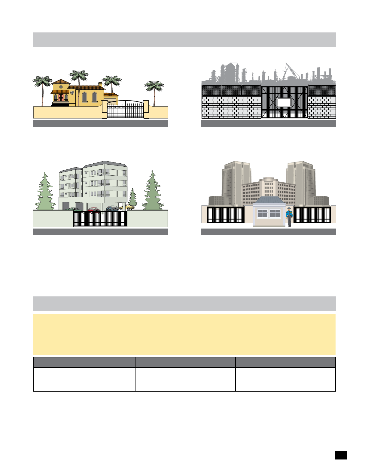
CLASS I
Residential Vehicular Gate Operator - A vehicular gate operator
(opener or system) intended for use in a home of one to four
single family dwellings, or a garage or parking area associated
therewith.
CLASS II
Commercial/General Access Vehicular Gate Operator - A
vehicular gate operator (opener or system) intended for use in
a commercial location or building such as a multi-family
housing unit (five or more single family units) hotel, garages,
retail store or other building servicing the general public.
CLASS III
Industrial/Limited Access Vehicular Gate Operator - A
vehicular gate operator (opener or system) intended for uses
in an industrial location, loading dock area or other location
not intended to service the general public.
SECURITY
CLASS IV
Restricted Access Vehicular Gate Operator - A vehicular gate
operator (opener or system) intended for use in a guarded
industrial location or buildings such as airport security area or
other restricted access locations not servicing the general
public, in which unauthorized access is prevented via
supervision by security personnel.
ul 325 required entrapment protection
This vehicular gate operator must be installed with at least two independent entrapment protection means as specified in the table and
definitions below.
The same type of device shall not be used for both entrapment protection means. Use of a single device to cover both the opening and
closing directions is in accordance with the requirement, however, a single device is not required to cover both directions. This operator
has been provided with type A entrapment protection. The installer is required to install additional entrapment protection devices in each
entrapment area.
Gate Type Class I & II
Swing Gate
Slide Gate
A - Inherent entrapment protection system.
B1 - Provision for connection of a non-contact sensor
(photoelectric sensor or the equivalent).
B2 - Provision for connection of a contact sensor
(edge device or the equivalent).
A, B1*, B2*, C, D
A, B1*, B2*, D
* B1 and B2 means of entrapment protection must be MONITORED.
C - Inherent adjustable clutch or pressure relief device.
D - Provision for connection of an actuating device
requiring continuous pressure to maintain opening
or closing motion of the gate.
E - An audio alarm.
Class III & IV
A, B1*, B2*, C, D, E
A, B1*, B2*, D, E
3
Page 6

ul 325 compliant
installation requirements
A Install the gate operator only when:
1 The operator is appropriate for the construction of the gate and the usage Class of the gate,
2 All openings of a horizontal slide gate are guarded or screened from the bottom of the gate to a minimum of 6 feet (1.83 m) above the
ground to prevent a 2-1/4 inch (57.2 mm) diameter sphere from passing through the openings anywhere in the gate, and in that
portion of the adjacent fence that the gate covers in the open position,
3 All exposed pinch points are eliminated or guarded, and
4 Guarding is supplied for exposed rollers.
B The operator is intended for installation only on gates used for vehicles. Pedestrians must be supplied with a separate access opening. The
pedestrian access opening shall be designed to promote pedestrian usage. Locate the gate such that persons will not come in contact with
the vehicular gate during the entire path of travel of the vehicular gate.
C The gate must be installed in a location so that enough clearance is supplied between the gate and adjacent structures when opening and
closing to reduce the risk of entrapment. Swinging gates shall not open into public access areas.
D The gate must be properly installed and work freely in both directions prior to the installation of the gate operator. Do not over-tighten the
operator clutch or pressure relief valve to compensate for a damaged gate.
E For gate operators utilizing Type D protection:
1 The gate operator controls must be placed so that the user has full view of the gate area when the gate is moving,
2 A gate operator shall additionally be provided with a placard that is marked in letters at least 1/4-in (6.4-mm) high with the word
“WARNING” and the following statement or the equivalent: “Moving Gate Has Potential of Inflicting Injury or Death - Do Not Start
Gate Unless Path is Clear”.
3 An automatic closing device (such as a timer, loop sensor, or similar device) shall not be employed, and
4 No other activation device shall be connected.
F Controls intended for user activation must be located at least six feet (6’) away from any moving part of the gate and where the user is
prevented from reaching over, under, around or through the gate to operate the controls. Outdoor or easily accessible controls shall have a
security feature to prevent unauthorized use.
The Stop and/or Reset button must be located in the line-of-sight of the gate. Activation of the reset control shall not cause the operator to start.
G
H A minimum of two (2) WARNING SIGNS shall be installed, one on each side of the gate where easily visible.
I For gate operators utilizing a non-contact sensor:
1 See instructions on the placement of non-contact sensors for each Type of application,
Care shall be exercised to reduce the risk of nuisance tripping, such as when a vehicle, trips the sensor while the gate is still moving, and
2
3 One or more non-contact sensors shall be located where the risk of entrapment or obstruction exists, such as the perimeter reachable
by a moving gate or barrier.
J For a gate operator utilizing a contact sensor:
1 One or more contact sensors shall be located where the risk of entrapment or obstruction exists, such as at the leading edge, trailing
edge, and post mounted both inside and outside of a vehicular horizontal slide gate.
2 One or more contact sensors shall be located at the bottom edge of a vehicular vertical lift gate.
3 One or more contact sensors shall be located at the pinch point of a vehicular vertical pivot gate.
4 A hardwired contact sensor shall be located and its wiring arranged so that the communication between the sensor and the gate
operator is not subjected to mechanical damage.
5 A wireless device such as one that transmits radio frequency (RF) signals to the gate operator for entrapment protection functions
shall be located where the transmission of the signals are not obstructed or impeded by building structures natural landscaping or
similar obstruction. A wireless device shall function under the intended end-use conditions.
6 One or more contact sensors shall be located on the inside and outside leading edge of a swing gate. Additionally, if the bottom edge
of a swing gate is greater than 6 inches (152 mm) above the ground at any point in its arc of travel, one or more contact sensors shall
be located on the bottom edge.
7 One or more contact sensors shall be located at the bottom edge of a vertical barrier (arm).
4
Page 7
intended use of
swing gate operator
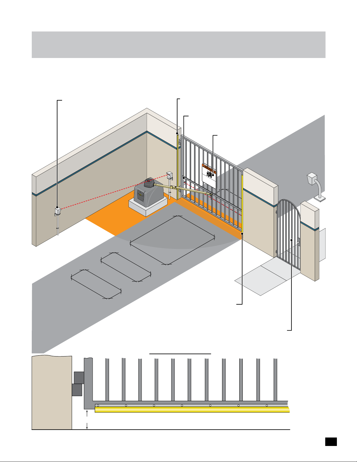
The operator is intended for use on a VEHICULAR slide gate ONLY. It is intended to be used WITH appropriate entrapment
protection safety devices and in-ground vehicle loop detection system. This operator has a inherent entrapment protection
system and requires additional external monitored entrapment protection devices (Non-contact Photocells or contact sensing
edges) for each entrapment area prior to gate operation.
Opening Direction Photocell: Helps
guard against the opening gate from
entrapment.
Area
Entrapment
Opening/Closing Direction 10K Sensing Edge: Helps
protect against entrapment in hinge area.
Closing Direction Photocell: Helps protect the gate
operator from accidentally closing on vehicles in the gate’s
closing path and entrapment.
Warning Signs: Should be installed
on both sides of gate area and
easily visible.
Moving Gate Can
Serious Inju
KEEP
w
it
C
hout
LE
Do not
AR!
prior
in
Ga
ry or Death
t
w
le
he gat
arning.
t
Caus
e ma
t
c
This
hildren operate
e area.
y
Pedes
entranc
m
ov
e
e at any
trians
e is
fo
t
he gat
m
time
r ve
us
t
hic
us
e or
e
les
s
play
eparate entranc
only.
e.
Entrapment Area
In-Ground Loops:
Help protect the gate
operator from accidentally
opening and/or closing on
vehicles in the gate’s path.
6” or More
Opening/Closing Direction 10K Sensing Edge: Helps
protect the gate operator from accidentally opening
and/or closing on vehicles in the gate’s path.
(Wireless Option)
Pedestrians MUST use a separate entrance.
The gate operator IS NOT intended to be
used on a PEDESTRIAN gate.
Bottom of Gate
NOTE: sensors
MUST be
MONITORED
and NORMALLY
CLOSED (N.C.)
OPENING/CLOSING direction Gate Protection 10K Sensing Edge on Bottom of Gate: If the bottom of
gate is 6 inches or higher above the ground, then a sensing edge should be installed for safety.
5
Page 8
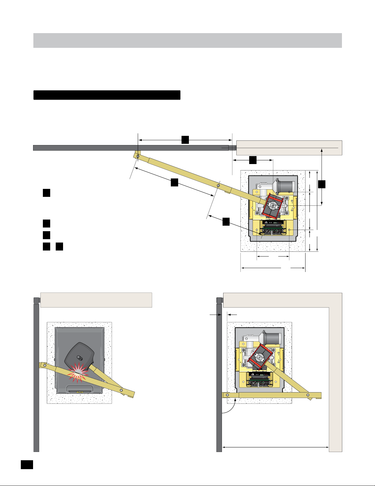
installation
Read and understand this entire manual before installation. Check with the local building department prior to installing this gate
operator to comply with local building code requirements. The gate must be installed in a location so that enough clearance is
supplied between the gate and adjacent structures when opening and closing to reduce the risk of entrapment. Swinging gates
should not open into public access areas.
Gate Operator position
The gate must be properly installed and work freely in both directions prior to installation of the gate operator.
Closed Position
Gate Bracket Pivot Point
A
Hinge Pivot Point
Illustrations not to scale
Measurement Guidelines
A Should be at least 1/4 the gate length.
NOTE: Uphill or heavy gates should be at least
1/3 gate length.
B 15” minimum for open gate clearance (2” thick gate).
C Distance “A” minus 17 inches (A - 17 = C).
D & E Arm should be 90° from gate when OPEN
and in the straight “locked” position when CLOSED.
Maximum arm length is 71 inches.
Open Position
Locked Position
Long Arm
D
Longer
than “E”
Arm
Pivot
Point
E
Shorter
than “D”
15” Min
Short Arm
2” Min
B
Concrete Pad
8”
C
Operator
LIMIT
LIMIT
CLOSED
OPEN
ERD
MC-200
JOG
Sensitivity
JOG
Motor Controller
Motor
GND
Cell
MATRIX
Photo
LEFT
RIGHT
Jog LT
Edge 1
Edge 2
ON-LINE
UL Entrap
Edge
OverLoad
Jog RT
5
4
1
3
POWER
MAX
2
ERD
12
16
LED ON
Edge
PhotoCell
Limit SW
13
15
14
POWER
POWER/SOLAR
IN
IN
TO MOTOR
CONTROLLER
BATTERY
BATTERY
BATTERY
MATRIX 1
PRIMARY
BACK-UP MODE
GATE
LEAVE
MAGLOCK
CLOSED
DELAY
OPEN
OPEN
PACK
IN
LEAVE
OPEN
MADE in USA
MAG
RIGHT
LEFT
OPEN
1 TIME
OFF
2Sec1.5Sec
LOCK
COM
NC
AUTOMATIC OPEN/CLOSE CONTROLS
Tamper NO
ANTI
GATE
SAFETYCENTEREXIT
TAILGATE
COM
TAMPER
GND
EXIT
OFFON
Tamper IN
CENTER
PHOTOCELL
UL
EDGE 1
SAFETY
MIN
MAX
OFF
ENTRAP
EDGE 2
CLOSE TIMER
ID PLUG
PARTIAL
MOTOR MOTION
ERROR
OPEN
ID
PLUG
UL ALARM 12V
ALARM RET
RESET
OPEN
STOPCLOSE
GND
POSITION
RECORDER
REVERSE SENSITIVITY
MAX
12VDC
GATE SPEED
MOTOR OVERLOAD
GND
OBD PORT
OPEN
BLACK BOX
GATE
MIN
NO LIMIT SWITCH /
COM
STATUS
CLAMP SLIPPING
24VDC
MAX
CLOSE
GND
LIMIT
BATTERY
SWITCH
ON-LINE
IN USE
MOTOR
ON-LINE
POWER
PRIMARY
SEC
GATE
GATE
24V
GND
PHOTOCELL
GND
STRIKE
GND
KEYPAD / RDR
GND
FIRE DEPT
GND
MAX OPEN
GND
RADIO SIG.
RADIO GND
OPEN
STOP
CLOSE
COM
GATE DISABLE
(+)
GND
(-)
(+)
GND
(-)
www.max.us.com
Made in USA
12”
24”
Outside Property
Inside Property
14”
8”
Pivot
Point
30”
Hood
LIMIT
LIMIT
CLOSED
2” Gate Frame
OPEN
ERD
MC-200
JOG
Sensitivity
JOG
Motor Controller
Motor
GND
Cell
MATRIX
Photo
LEFT
RIGHT
Jog LT
Edge 1
Edge 2
ON-LINE
UL Entrap
Edge
OverLoad
Jog RT
5
4
1
3
POWER
MAX
2
ERD
12
16
LED ON
Edge
PhotoCell
Limit SW
13
15
14
POWER
POWER/SOLAR
IN
IN
TO MOTOR
CONTROLLER
BATTERY
BATTERY
BATTERY
MATRIX 1
PRIMARY
BACK-UP MODE
GATE
LEAVE
MAGLOCK
CLOSED
DELAY
OPEN
OPEN
PACK
IN
LEAVE
OPEN
MADE in USA
MAG
RIGHT
LEFT
OPEN
1 TIME
OFF
2Sec1.5Sec
LOCK
COM
NC
AUTOMATIC OPEN/CLOSE CONTROLS
Tamper NO
ANTI
GATE
SAFETYCENTEREXIT
TAILGATE
COM
TAMPER
GND
EXIT
OFFON
Tamper IN
CENTER
PHOTOCELL
UL
EDGE 1
SAFETY
MIN
MAX
OFF
ENTRAP
EDGE 2
CLOSE TIMER
ID PLUG
PARTIAL
MOTOR MOTION
ERROR
OPEN
ID
PLUG
UL ALARM 12V
ALARM RET
RESET
STOPCLOSE
OPEN
GND
POSITION
RECORDER
REVERSE SENSITIVITY
MAX
12VDC
GATE SPEED
MOTOR OVERLOAD
GND
OBD PORT
OPEN
BLACK BOX
GATE
MIN
NO LIMIT SWITCH /
COM
STATUS
CLAMP SLIPPING
24VDC
MAX
CLOSE
GND
LIMIT
BATTERY
SWITCH
ON-LINE
IN USE
MOTOR
ON-LINE
POWER
PRIMARY
SEC
GATE
GATE
24V
GND
PHOTOCELL
GND
STRIKE
GND
KEYPAD / RDR
GND
FIRE DEPT
GND
MAX OPEN
GND
RADIO SIG.
RADIO GND
OPEN
STOP
CLOSE
COM
GATE DISABLE
(+)
GND
(-)
(+)
GND
(-)
www.max.us.com
Made in USA
Preferred arm position
is 90° from open gate.
DO NOT allow arm to touch
hood in gate’s OPEN position.
TOO MUCH STRESS is put on
the arm in this position during
gate operation.
See page 10 for arm
position options and
connection to gate.
NOTE: If dimension between OPEN gate
and wall is 20” to 32” then compact
installation is necessary, see page 12.
Wall
6
Page 9
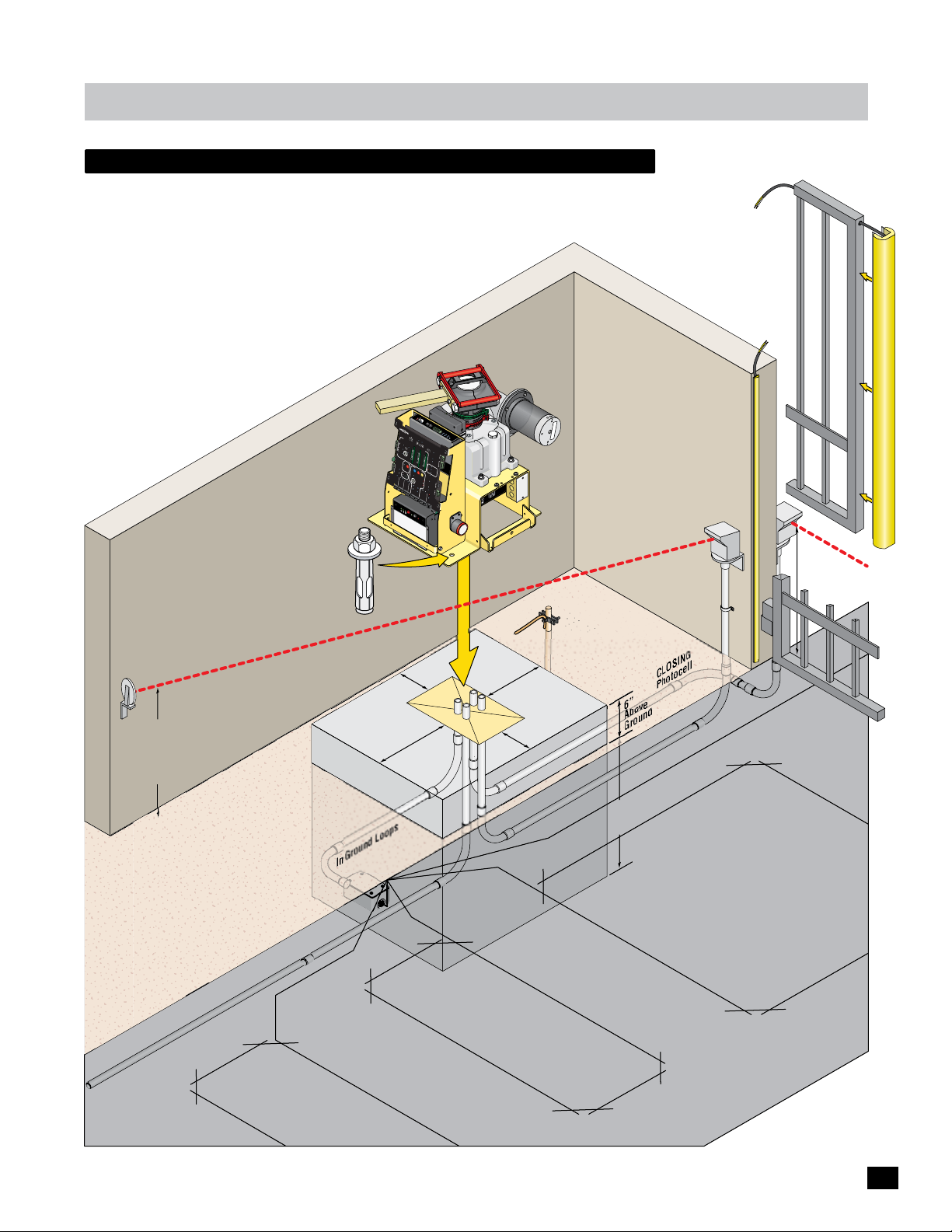
installation
recommended Gate Operator layout
Use for VEHICULAR traffic ONLY. Pedestrians MUST use a separate
entrance. Install appropriate entrapment protection safety devices
for the OPENING direction and CLOSING direction of gate cycling.
Install in-ground SAFETY and CENTER loops. Install a GROUNDING
ROD within 10 ft of operator. An “Optional” EXIT loop can be
installed if desired.
NOTE: ONE Entrapment protection
sensor MUST installed or operator
will NOT function. It MUST be
MONITORED and NORMALLY
CLOSED (N.C.)
O
M
verL
o
to
r
o
ad
E
S
E
RD
e
RD
n
s
i
t
i
v
i
t
y
5
1
2
4
1
3
3
1
4
1
1
5
6
JO
M
LE
G
AX
L
E
F
D
T
O
N
JO
R
G
IG
H
T
T
L
T
g
MA
o
R
J
og
1
T
J
GND
R
e
2
I
dg
e
X
o
E
dg
ot
1
E
h
l
l
P
e
C
MA
O
T
N
R
MA
-
I
LI
X
B
N
DE
E
A
BAC
TT
i
n
US
E
E
L
d
K-
i
R
mi
A
g
1
e
Y
t
U
S
W
P
M
U
2
L
M
o
E
n
to
MC
L
O
t
r
E
L
E
ap
d
E
DE
A
r
g
A
V
e
C
Co
V
E
L
E
-
OP
OS
P
2
POWE
h
ntr
o
E
E
t
0
D
o
C
o
0
e
l
PR
lle
l
r
I
R
M
OP
AR
E
N
G
1
Y
ATE
T
I
ME
O
P
E
N
L
E
F
IC
T
O
P
O
EN
R
PEN/CLO
I
G
H
T
M
AG
D
L
R
O
A
SE CO
DE
CK
O
X
I
EXIT
O
B
LA
R
F
F
T
Y
A
PWR 24V -
1
.
M
5
S
N
ec
T
RS-485 (-) -
ROL
2
RS-485 (+) -
S
ec
CENT
M
AG
GND -
S
E
LOCK
R
SAF
E
T
COM
Y
NC
GA
M
TE
R
A
T
L
A
A
M
Ta
PE
CH
m
T
I
W
R
pe
S
T
I
r
M
I
NO
L
K
C
A
P
Y
R
E
CO
T
T
A
B
M
S
T
U
G
P
Tam
N
ND
I
R
O
T
O
pe
M
r
IN
r In
e
w
Po
PH
MOT
U
OT
L
O
OCE
R
MO
L
R
L
T
O
I
ENTR
O
N
OT
EDG
A
M
P
E
1
OPE
N
E
MAX
DG
E
ST
2
OP
GA
ID PLUG
TE
CLOS
R
S
E
M
PEED
V
I
ERRO
N
E
R
E
S
E
S
MA
E
R
N
X
S
I
M
T
U
I
O
V
L
T
I
T
ALAR
OR
Y
OV
E
RL
ALAR
M
NO
O
12
A
L
D
I
MI
V
M
C
T
L
RE
A
S
MP
W
I
RE
T
T
S
C
L
H
I
S
P
/
P
E
I
T
NG
GN
LI
G
MIT
D
L
AT
S
W
L
E
ITCH
ST
ON
E
AT
-L
I
U
NE
S
OC
M
T
OTO
ON-LIN
OPE
P
R
RI
M
N
A
R
E
GA
Y
CO
T
E
GND
M
CLOS
D
S
(+)
N
E
C
G
E
)
GA
-
T
(
E
E
L
D
BA
+)
(
B
N
TT
N
G
A
E
-)
R
E
E
(
S
Y
I
N
OP
US
DI
OP
T
OS
E
S
L
E
C
OM
T
PO
C
W
GA
ER
V
D
4
2
GN
MA
F
F
Ba
X
R
t
t
B
epl
er
r
y
C
y
ac
M
-
B
e
o
7
a
d
t
u
ter
l
e
T
y
ES
T
Ba
t
t
Ba
e
r
y
t
te
r
y
IN
E
r
r
or
:
G
N
I
,
N
e
R
ir
f
t
a
s
WA
in
e
a
p
g
ty
a
e
m
a
s
SSEMENT
I
T
t
t
e
m
VER
o
c
r
A
p
’in
d
m
o
s
t
c
e
s
u
e
q
m
is
r
ê
.
s
m
e
l
e
a
d
n
i
m
o
n
p
Am
7
E
S
FU
n
O
ER
W
O
P
15
1
f
f
O
Illustration not to scale
Secure gate operator
to concrete pad with
six (6) 1/2” x 3” (min)
sleeve anchors.
N
AU
T
O
M
A
T
AN
E
X
T
T
I
T
AI
I
LG
AT
E
ON
O
F
C
F
E
NT
E
R
S
A
F
E
T
Y
MI
N
O
M
F
A
F
CLOSE TI
X
I
D
M
ER
PLUG
P
A
R
T
IAL
O
P
E
N
1
2
V
DC
GN
D
POSI
RE
T
IO
2
CO
4
V
N
DC
R
DE
G
ND
R
OB
D
B
POR
L
A
C
T
K
BO
X
G.
I
D
S
O
GN
T
DI
P
O
N
DI
E
RA
DE
R
RA
OP
RE
D
I
RD
X
F
E
/
A
GN
K
D
M
A
RI
GND
T
P
S
Y
E
GND
K
GND
HO
P
B
a
t
t
e
r
y
V
E
o
lt
a
g
1
e
/
2
F
O
N
/O
Batte
1/2
Run wiring to
GA
TE OPERATOR
10K Sensing Edge
Mount on end of gat
.
and hinge area.
Run wiring to
GA
TE OPER
e
ATOR.
Max Mini Edge
Support Bar
n
io
t
c
e
t
o
r
e
p
d
th
e
h
u
it
in
t
w
n
y
.
l
o
e
c
n
s
r
o
u
o
f
e
f
c
F
s
o
s
la
a
le
g
p
p
re
e
tin
re
t
a
n
r
n
r
le
o
u
d
c
ib
o
n
s
n
p
u
:
io
f
t
s
n
c
e
e
u
t
u
r
o
e
r
iq
t
p
is
ilis
t
r
la
u
é
t
e
,
c
r
ie
a
r
d
a
n
e
c
t
e
e
p
y
x
a
m
A
3
C
A
V
CLOSING
Photocell Beam
21” Hig
h
Gr
Rod
oun
d
Support Bar
OPENING Photocell Beam
Beam
Height
ust
J
Above
Gate
Operator
t AC Power (Required)
Inpu
24”x 30”
Pad
In-Ground Loops
Exit Loop
(Optional)
5.5
12”
10”
”
Conduit
12” x 8.5”
Area
5.5
”
NING Ph
OPE
oto
cell
6”
Abov
G
24”
Min
e
round
CLOSING
Photocel
l
om Safety Loop
r
F
Center Loop
Safety Loop
7
Page 10
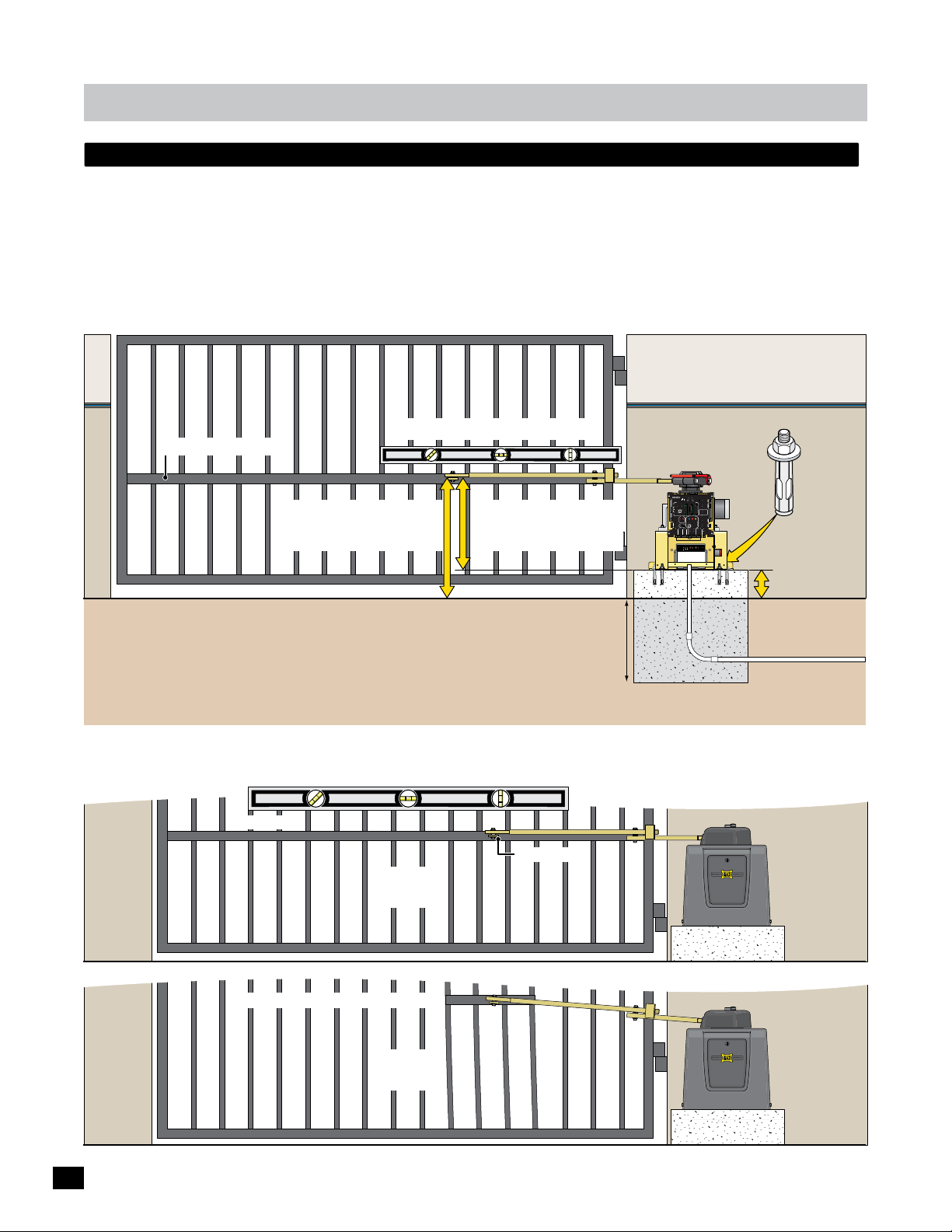
installation
YES
NO
layout and arm height of 1400/2200/FAST or 1400hp
The gate must be properly installed and work freely in both directions prior to the installation of the gate operator.
See “Gate Operator Position” on page 6 for operator position and “Arm Connection to Gate” on page 10.
Conduit Guidelines and Suggestions (See page 7)
• REQUIRED - AC input power wire.
• REQUIRED - Entrapment protection (photocell and/or sensing edge). See page 13.
• Normally open photocell. See page 13.
• In-ground loop wires. See page 14.
Illustration not to scale
Secure gate operator
Support Bar: See below
Arm MUST be installed level.
1400/2200/FAST = 25”
1400HP = 33.5”
19”=1400/2200/FAST
27.5”=1400HP
to concrete pad with
six (6) 1/2” x 3”
(min) sleeve anchors.
PRIMARY
BATTERY
MATRIX 1
GATE
BACK-UP MODE
LEAVE
MAGLOCK
CLOSED
DELAY
OPEN
OPEN
LEAVE
OPEN
MADE in USA
MAG
RIGHT
LEFT
OPEN
1 TIME
OFF
2Sec1.5Sec
LOCK
COM
NC
AUTOMATIC OPEN/CLOSE CONTROLS
Tamper NO
ANTI
GATE
SAFETYCENTEREXIT
TAILGATE
COM
TAMPER
GND
BOARD
EXIT
OFFON
Tamper IN
MATRIX
CENTER
RS-485 (+) -
PHOTOCELL
RS-485 (-) -
PWR 24V -
UL
EDGE 1
SAFETY
MIN
MAX
OFF
ENTRAP
EDGE 2
GND -
CLOSE TIMER
ID PLUG
PARTIAL
MOTOR MOTION
ERROR
OPEN
ID
INPUTS
PACK
SWITCH
Power In
MOTOR
MOTOR
PLUG
BATTERY
ALARM
LIMIT
UL ALARM 12V
ALARM RET
RESET
OPEN
STOP CLOSE
POSITION
GND
RECORDER
REVERSE SENSITIVITY
MAX
12VDC
GATE SPEED
MOTOR OVERLOAD
GND
OBD PORT
OPEN
BLACK BOX
GATE
MIN
NO LIMIT SWITCH /
COM
STATUS
24VDC
CLAMP SLIPPING
MAX
CLOSE
GND
LIMIT
BATTERY
SWITCH
ON-LINE
IN USE
MOTOR
ON-LINE
POWER
PRIMARY
SEC
GATE
GATE
24V
GND
PHOTOCELL
GND
STRIKE
GND
KEYPAD / RDR
GND
FIRE DEPT
GND
MAX OPEN
GND
RADIO SIG.
RADIO GND
OPEN
STOP
CLOSE
COM
GATE DISABLE
(+)
GND
(-)
(+)
GND
(-)
MAX BC-7
Battery Voltage
Battery Module
EF1/2
ON/OFF
Replace
TEST
Battery IN
Battery
Battery
Battery
Error
1/2
6” Above Ground
Ground Level
Check local building
codes in your area for
“Optional” Input Power Note:
24VDC low voltage power wires can be run
from a remote power supply (MAX Magic
Box) to power the gate operator if desired.
See page 11 for more information.
Concrete Depth Note: The heavier the gate, the deeper the concrete
pad should be. At least two feet recommended for heavier gate.
depth of concrete
before installation.
Concrete Pad
Conduit
Input Power
Support Bar
A support bar should be installed at the gate bracket height across the ENTIRE gate to keep the gate pickets from bending.
Support Bar
Gate Bracket
YES
Support Bar Too High & Not Long Enough
NO
8
Page 11
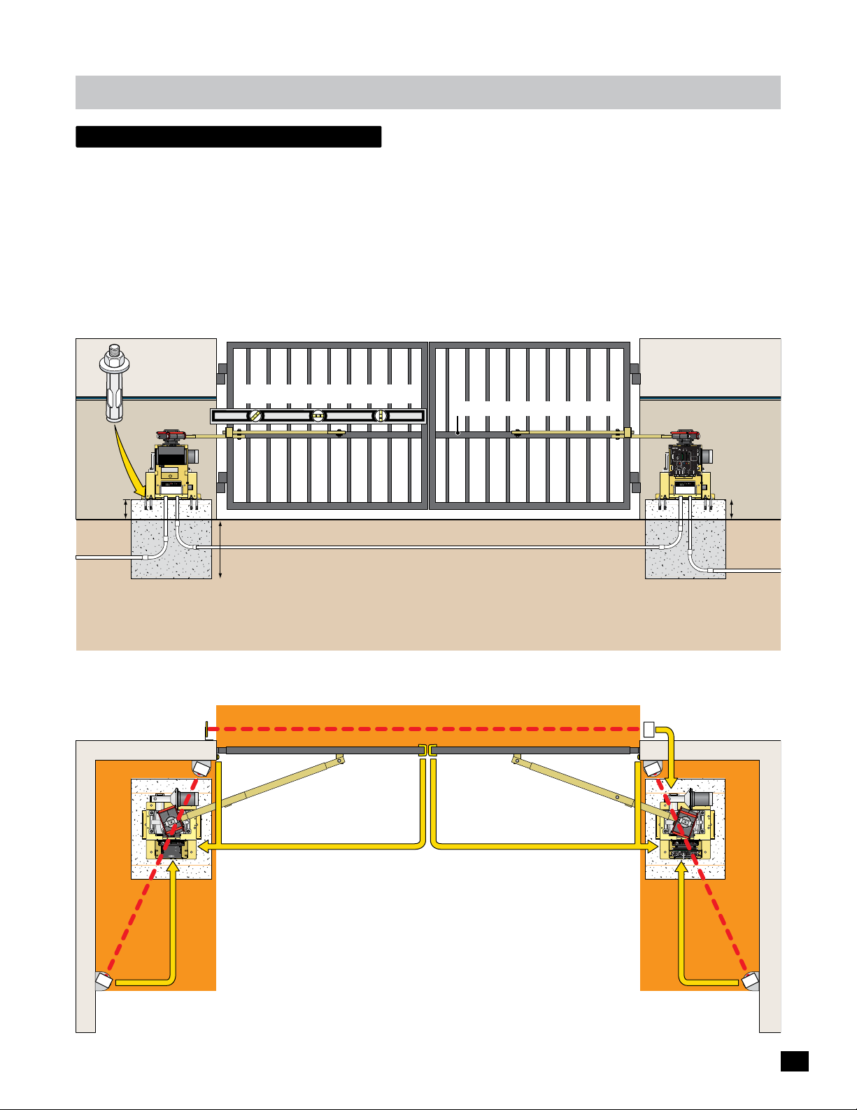
installation
dual Gate Operators
The gates must be properly installed and work freely in both directions prior to the installation of the dual gate operators.
See “Gate Operator Position” on page 6 for operator positions and previous page for arm height.
Conduit Guidelines and Suggestions
• REQUIRED - Run AC input power wire to EACH gate operator.
• REQUIRED - Entrapment protection (photocell and/or sensing edge) to EACH Corresponding
GATE OPERATOR. (see below & page 13)
Secure EACH gate
operator to concrete pad
with six (6) 1/2”x 3” (min)
sleeve anchors.
Secondary
Operator
1/2
NO Matrix 1
BOARD
MATRIX
RS-485 (+) -
RS-485 (-) -
PWR 24V -
GND -
INPUTS
PACK
SWITCH
MOTOR
BATTERY
ALARM
LIMIT
MAX BC-7
Battery Voltage
Battery Module
EF1/2
ON/OFF
Replace
TEST
Battery IN
Battery
Battery
Battery
Error
6” Above
Ground
Power In
MOTOR
• Normally open photocell to the PRIMARY OPERATOR. (page 13)
• In-ground loop wires to the PRIMARY OPERATOR. (page 14)
Arms MUST be installed level.
Support Bars: See bottom of page 8.
Illustration not to scale
Primary
Operator
Matrix 1
BATTERY
MATRIX 1
PRIMARY
BACK-UP MODE
GATE
LEAVE
MAGLOCK
CLOSED
DELAY
OPEN
OPEN
LEAVE
OPEN
MADE in USA
MAG
RIGHT
LEFT
OPEN
1 TIME
OFF
2Sec1.5Sec
LOCK
COM
NC
AUTOMATIC OPEN/CLOSE CONTROLS
Tamper NO
ANTI
GATE
SAFETYCENTEREXIT
TAILGATE
COM
TAMPER
GND
BOARD
EXIT
OFFON
Tamper IN
MATRIX
CENTER
RS-485 (+) -
PHOTOCELL
RS-485 (-) -
PWR 24V -
UL
EDGE 1
SAFETY
MAX
MIN
OFF
ENTRAP
EDGE 2
GND -
CLOSE TIMER
ID PLUG
PARTIAL
MOTOR MOTION
ERROR
OPEN
ID
INPUTS
PACK
SWITCH
Power In
MOTOR
MOTOR
PLUG
BATTERY
ALARM
LIMIT
UL ALARM 12V
ALARM RET
RESET
OPEN
STOPCLOSE
POSITION
GND
RECORDER
REVERSE SENSITIVITY
MAX
12VDC
GATE SPEED
MOTOR OVERLOAD
GND
OBD PORT
OPEN
BLACK BOX
GATE
MIN
NO LIMIT SWITCH /
COM
STATUS
CLAMP SLIPPING
24VDC
MAX
CLOSE
GND
LIMIT
BATTERY
SWITCH
ON-LINE
IN USE
MOTOR
ON-LINE
POWER
PRIMARY
SEC
GATE
GATE
24V
GND
PHOTOCELL
GND
STRIKE
GND
KEYPAD / RDR
GND
FIRE DEPT
GND
MAX OPEN
GND
RADIO SIG.
RADIO GND
OPEN
STOP
CLOSE
COM
GATE DISABLE
(+)
GND
(-)
(+)
GND
(-)
MAX BC-7
Battery Voltage
Battery Module
EF1/2
ON/OFF
Replace
TEST
Battery IN
Battery
Battery
Battery
Error
6” Above
Ground
Conduit
Input
Power
Concrete Depth Note: The heavier the gates, the deeper the concrete
pads should be. At least two feet recommended for heavier gates.
Check local building codes in your area for
depth of concrete before installation.
Conduit
Input
“Optional” Input Power Note:
Power
24VDC low voltage power wires can be run from a remote
power supply (MAX Magic Boxes) to power the gate
operators if desired. See page 11 for more information.
Each entrapment protection device MUST be connected to corresponding gate operator.
Dual Gates CLOSING direction Thru-Beam Photocell ONLY:
See separate wiring instruction sheet.
To Matrix 1 SEC GATE input Conduit
Reflector
Illustrations not to scale
LIMIT
LIMIT
CLOSED
OPEN
ERD
JOG
Sensitivity
JOG
GND
Cell
Motor Controller
Motor
MATRIX
Photo
Jog LT
Edge 1
Edge 2
LEFT
RIGHT
Jog RT
ON-LINE
Edge
UL Entrap
OverLoad
5
4
1
3
MAX
2
ERD
12
16
LED ON
Edge
PhotoCell
Limit SW
13
15
14
POWER
POWER/SOLAR
IN
IN
TO MOTOR
CONTROLLER
BATTERY
BATTERY
PACK
IN
www.max.us.com
Made in USA
Entrapment Area
Entrapment Area
OPENING/CLOSING direction Sensing Edges
OPENING/CLOSING
direction Mini
Sensing Edge
to Secondary Operator
MC-200
POWER
MC-200 Edge 2 or Photo Cell
Secondary Operator
NO Matrix 1
to Secondary Operator
MC-200 Edge 2 or Photo Cell
CLOSING direction Photocell
OPENING/CLOSING
direction Mini
Sensing Edge
to Primary Operator
MC-200 Edge 2 or Photo Cell
Primary Operator
Matrix 1
to Primary Operator
MC-200 Edge 2 or Photo Cell
To MC-200 EDGE 1 Input
Entrapment Area
LIMIT
LIMIT
CLOSED
OPEN
ERD
MC-200
JOG
Sensitivity
JOG
GND
Cell
Motor Controller
Motor
MATRIX
Photo
Jog LT
Edge 1
Edge 2
LEFT
RIGHT
Jog RT
ON-LINE
Edge
UL Entrap
OverLoad
5
4
1
3
POWER
MAX
2
ERD
12
16
LED ON
Edge
PhotoCell
Limit SW
13
15
14
POWER
POWER/SOLAR
IN
IN
TO MOTOR
CONTROLLER
BATTERY
BATTERY
BATTERY
MATRIX 1
PRIMARY
BACK-UP MODE
GATE
LEAVE
MAGLOCK
CLOSED
DELAY
OPEN
OPEN
PACK
IN
LEAVE
OPEN
MADE in USA
MAG
RIGHT
LEFT
OPEN
1 TIME
OFF
2Sec1.5Sec
LOCK
COM
NC
AUTOMATIC OPEN/CLOSE CONTROLS
Tamper NO
ANTI
GATE
SAFETYCENTEREXIT
TAILGATE
COM
TAMPER
GND
EXIT
OFFON
Tamper IN
CENTER
PHOTOCELL
UL
EDGE 1
SAFETY
MIN
MAX
OFF
ENTRAP
EDGE 2
CLOSE TIMER
ID PLUG
PARTIAL
MOTOR MOTION
ERROR
OPEN
ID
PLUG
UL ALARM 12V
ALARM RET
RESET
STOPCLOSE
OPEN
POSITION
GND
RECORDER
REVERSE SENSITIVITY
MAX
12VDC
GATE SPEED
MOTOR OVERLOAD
GND
OBD PORT
OPEN
BLACK BOX
GATE
MIN
NO LIMIT SWITCH /
COM
STATUS
CLAMP SLIPPING
24VDC
MAX
CLOSE
GND
LIMIT
BATTERY
SWITCH
ON-LINE
IN USE
MOTOR
ON-LINE
POWER
PRIMARY
SEC
GATE
GATE
24V
GND
PHOTOCELL
GND
STRIKE
GND
KEYPAD / RDR
GND
FIRE DEPT
GND
MAX OPEN
GND
RADIO SIG.
RADIO GND
OPEN
STOP
CLOSE
COM
GATE DISABLE
(+)
GND
(-)
(+)
GND
(-)
www.max.us.com
Made in USA
OPENING direction Photocell OPENING direction Photocell
See page 13 for installation instructions.
See pages 17-18 for wiring instructions.
9
Page 12

installation
arm position options
High Traffic Arm Option
Gates in Closed Position
Retro-Fit Arm Option
When replacing an existing gate operator, the arm may not be able
to conform to the preferred arm position (90° from gate in open
position). The positions illustrated below can be acceptable as long
as the gate operator cycles smoothly and there is NO gate hesitation
when gate starts cycling in either direction.
90°
Gate in Opened Position
90°
Gate in Opened Position
arm connection to gate
After you’re satisfied testing the arm in the FULL OPEN and FULL CLOSED positions, weld gate bracket and arm.
Illustrations not to scale
Full Closed
Arms are NOT installed in LOCKED position.
If a vehicle tries to push gates
open, arms will give when NOT
in the locked position and allow
gates to move without damaging
the gate operators.
The tamper relay will be
activated for a few seconds
which will trigger a camera or
alarm system if desired.
Locked Position
LIMIT
LIMIT
CLOSED
OPEN
MC-200
ERD
JOG
Sensitivity
JOG
GND
Motor Controller
Cell
Motor
MATRIX
Photo
Jog LT
Edge 1
LEFT
Edge 2
RIGHT
Jog RT
ON-LINE
Edge
UL Entrap
OverLoad
5
4
1
3
POWER
MAX
2
ERD
12
16
LED ON
PhotoCellEdge
Limit SW
13
15
14
POWER
POWER/SOLAR
IN
IN
TO MOTOR
CONTROLLER
BATTERY
BATTERY
PRIMARY
BATTERY
MATRIX 1
GATE
BACK-UP MODE
LEAVE
MAGLOCK
CLOSED
DELAY
OPEN
OPEN
PACK
IN
OPEN
LEAVE
MADE in USA
MAG
RIGHT
LEFT
1 TIME
OPEN
2Sec1.5Sec
OFF
LOCK
COM
NC
AUTOMATIC OPEN/CLOSE CONTROLS
Tamper NO
ANTI
GATE
SAFETYCENTEREXIT
TAILGATE
COM
TAMPER
GND
EXIT
OFFON
Tamper IN
CENTER
PHOTOCELL
UL
EDGE 1
SAFETY
MAX
MIN
OFF
ENTRAP
EDGE 2
CLOSE TIMER
ID PLUG
PARTIAL
MOTOR MOTION
ERROR
OPEN
ID
PLUG
UL ALARM 12V
ALARM RET
RESET
OPEN
STOPCLOSE
POSITION
GND
RECORDER
REVERSE SENSITIVITY
MAX
12VDC
GATE SPEED
MOTOR OVERLOAD
GND
OBD PORT
OPEN
BLACK BOX
GATE
MIN
NO LIMIT SWITCH /
COM
STATUS
24VDC
CLAMP SLIPPING
MAX
CLOSE
GND
LIMIT
BATTERY
SWITCH
ON-LINE
IN USE
MOTOR
POWER
ON-LINE
PRIMARY
SEC
GATE
GATE
24V
GND
PHOTOCELL
GND
STRIKE
GND
KEYPAD / RDR
GND
FIRE DEPT
GND
MAX OPEN
GND
RADIO SIG.
RADIO GND
OPEN
STOP
CLOSE
COM
GATE DISABLE
(+)
GND
(-)
(+)
GND
(-)
www.max.us.com
Made in USA
Full Open
Preferred arm position
is 90° from open gate.
Re-Attach Arm to Operator:
Limit pin MUST fit into slot in
bottom of release handle clamp
directly under the arm when
re-attaching arm to operator.
Release Handle Clamp
Arm
Limit Tabs
Slot
Limit Pin
weld completely around arm tubing and gate bracket.
Arm MUST be installed level.
Gate Bracket
Assembly
Arm Elbow
Assembly
ID
PLUG
12VDC
GND
24VDC
GND
MATRIX 1
MADE in USA
EXIT
CENTER
PWR 24V -
SAFETY
AUTOMATIC OPEN/CLOSE CONTROLS
ANTI
TAILGATE
RS-485 (-) -
MIN
GND -
CLOSE TIMER
FIRE DEPT
RADIO SIG.
RADIO GND
LIMIT
LIMIT
CLOSED
OPEN
MC-200
ERD
JOG
Sensitivity
JOG
GND
Motor Controller
Cell
Motor
MATRIX
Photo
Jog LT
Edge 1
LEFT
Edge 2
RIGHT
Jog RT
ON-LINE
Edge
UL Entrap
OverLoad
5
4
1
3
POWER
MAX
2
ERD
12
16
LED ON
PhotoCellEdge
Limit SW
13
15
14
POWER
POWER/SOLAR
IN
IN
TO MOTOR
CONTROLLER
BATTERY
BATTERY
PRIMARY
BATTERY
MATRIX 1
GATE
BACK-UP MODE
LEAVE
MAGLOCK
CLOSED
DELAY
OPEN
OPEN
PACK
IN
OPEN
LEAVE
MADE in USA
MAG
RIGHT
LEFT
1 TIME
OPEN
2Sec1.5Sec
OFF
LOCK
COM
NC
AUTOMATIC OPEN/CLOSE CONTROLS
Tamper NO
ANTI
GATE
SAFETYCENTEREXIT
TAILGATE
COM
TAMPER
GND
EXIT
OFFON
Tamper IN
CENTER
PHOTOCELL
UL
EDGE 1
SAFETY
MAX
MIN
OFF
ENTRAP
EDGE 2
CLOSE TIMER
ID PLUG
PARTIAL
MOTOR MOTION
ERROR
OPEN
ID
PLUG
UL ALARM 12V
ALARM RET
RESET
OPEN
STOPCLOSE
POSITION
GND
RECORDER
REVERSE SENSITIVITY
MAX
12VDC
GATE SPEED
MOTOR OVERLOAD
GND
OBD PORT
OPEN
BLACK BOX
GATE
MIN
NO LIMIT SWITCH /
COM
STATUS
24VDC
CLAMP SLIPPING
MAX
CLOSE
GND
LIMIT
BATTERY
SWITCH
ON-LINE
IN USE
MOTOR
POWER
ON-LINE
PRIMARY
SEC
GATE
GATE
24V
GND
PHOTOCELL
GND
STRIKE
GND
KEYPAD / RDR
GND
FIRE DEPT
GND
MAX OPEN
GND
RADIO SIG.
RADIO GND
OPEN
STOP
CLOSE
COM
GATE DISABLE
(+)
GND
(-)
(+)
GND
(-)
www.max.us.com
Made in USA
PRIMARY
BATTERY
GATE
BACK-UP MODE
LEAVE
MAGLOCK
CLOSED
DELAY
OPEN
OPEN
LEAVE
OPEN
MAG
RIGHT
LEFT
OPEN
1 TIME
OFF
2Sec1.5Sec
LOCK
COM
NC
Tamper NO
GATE
SAFETYCENTEREXIT
COM
TAMPER
GND
BOARD
OFFON
Tamper IN
MATRIX
RS-485 (+) -
PHOTOCELL
UL
EDGE 1
MAX
OFF
ENTRAP
EDGE 2
ID PLUG
PARTIAL
MOTOR MOTION
ERROR
OPEN
INPUTS
PACK
SWITCH
Power In
MOTOR
MOTOR
BATTERY
ALARM
LIMIT
UL ALARM 12V
ALARM RET
RESET
OPEN
STOP CLOSE
POSITION
GND
RECORDER
REVERSE SENSITIVITY
MAX
GATE SPEED
MOTOR OVERLOAD
OBD PORT
OPEN
BLACK BOX
GATE
MIN
NO LIMIT SWITCH /
COM
STATUS
CLAMP SLIPPING
MAX
CLOSE
LIMIT
BATTERY
SWITCH
ON-LINE
IN USE
MOTOR
ON-LINE
POWER
PRIMARY
SEC
GATE
GATE
24V
GND
PHOTOCELL
GND
STRIKE
GND
KEYPAD / RDR
GND
GND
MAX OPEN
GND
OPEN
STOP
CLOSE
COM
GATE DISABLE
(+)
GND
(-)
(+)
GND
(-)
MAX BC-7
Battery Voltage
Battery Module
EF1/2
ON/OFF
Replace
TEST
Battery IN
Battery
Battery
Battery
Error
10
Page 13
installation
W
A
R
N
I
N
G
H
I
G
H
V
O
L
T
A
G
E
W
A
R
N
I
N
G
H
IG
H
V
O
L
T
A
G
E
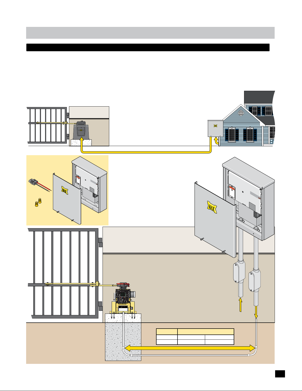
optional remote power supply kit - max magic box
A remote power supply is for installations where it is too costly or difficult to trench a 115/230 VAC power line to the operator
but instead run a low voltage power line to the operator. A MAX Magic Box Kit (sold separately) is required to remotely install a
Remote MAX Megatron Toroid box.
Install the MAX Magic Box near the 115 VAC or 230 VAC input AC power source, up to 1000 ft away from gate operator.
NOTE: A MAX Magic Box kit is required for EACH gate operator when using dual gate operators.
Operator
MAX Magic Box
Near Power Source
MAX Magic Box Kit
Sold Separately
Power/Solar In
Connector
Wire
Nuts
Cove
r
Cabinet
PLY
4
UP
S
-2
S
R
E
P
W
X
O
P
A
M
Remote Toroid
15 Amp Bo
WA
RNING
!
x
H
IGH
VO
LT
AG
d
i
s
c
po
o
E
n
w
ne
e
s
c
r
e
t
b
r
v
ef
ic
o
in
r
e
g
u
n
i
t
Distance - See table below
115/230 VAC Power Source
2-Wires, 24VDC Low Voltage Power
SA
U
in
e
d
a
M
MP
A
E
S
7
U
F
F
R
E
OF
W
O
N
P
O
N
I
C
A
S
elec
t Input V
1
15
VA
C
230V
or
ol
t
230VA
a
ge:
C
warranty
VOID
if la
ED
b
R
el is
E
MOVED
At MAX Magic Box
See page 20 for
MAX Magic Box
wiring instructions.
not suppl
At Gate
Operator
PRIMARY
BATTERY
MATRIX 1
GATE
BACK-UP MODE
LEAVE
MAGLOCK
CLOSED
DELAY
OPEN
OPEN
LEAVE
OPEN
MADE in USA
MAG
RIGHT
LEFT
OPEN
1 TIME
OFF
2Sec1.5Sec
LOCK
COM
NC
AUTOMATIC OPEN/CLOSE CONTROLS
Tamper NO
ANTI
GATE
SAFETYCENTEREXIT
TAILGATE
COM
TAMPER
GND
BOARD
EXIT
OFFON
Tamper IN
MATRIX
CENTER
RS-485 (+) -
PHOTOCELL
RS-485 (-) -
PWR 24V -
UL
EDGE 1
SAFETY
MIN
MAX
OFF
ENTRAP
EDGE 2
GND -
CLOSE TIMER
ID PLUG
PARTIAL
MOTOR MOTION
ERROR
OPEN
ID
INPUTS
PACK
SWITCH
Power In
MOTOR
MOTOR
PLUG
BATTERY
LIMIT
ALARM
UL ALARM 12V
ALARM RET
RESET
OPEN
STOP CLOSE
POSITION
GND
RECORDER
REVERSE SENSITIVITY
MAX
12VDC
GATE SPEED
MOTOR OVERLOAD
GND
OBD PORT
OPEN
BLACK BOX
GATE
MIN
NO LIMIT SWITCH /
COM
STATUS
24VDC
CLAMP SLIPPING
MAX
CLOSE
GND
LIMIT
BATTERY
SWITCH
ON-LINE
IN USE
MOTOR
ON-LINE
POWER
PRIMARY
SEC
GATE
GATE
24V
GND
PHOTOCELL
GND
STRIKE
GND
KEYPAD / RDR
GND
FIRE DEPT
GND
MAX OPEN
GND
RADIO SIG.
RADIO GND
OPEN
STOP
CLOSE
COM
GATE DISABLE
(+)
GND
(-)
(+)
GND
(-)
MAX BC-7
Battery Voltage
Battery Module
EF1/2
ON/OFF
Replace
TEST
Battery IN
Battery
Battery
Battery
Error
Conduit
ied
Inpu
Y
PPL
SU
R
WE
O
P
MAX PS-24
Remote T
15 Amp Bo
VO
oroid
W
A
R
NI
N
G
!
HI
GH
LT
A
di
s
G
co
p
E
o
n
w
n
e
e
se
ct
r
b
rv
e
i
f
c
o
in
r
e
g
unit
tage
l
High
Vo
Input Power
t AC
Power
SA
U
n
i
e
d
a
M
MP
A
E
S
7
U
F
R
FF
O
WE
N
PO
O
N
I
C
A
x
Se
lect
1
In
1
5
p
V
u
AC
t
V
230V
or 23
olt
a
ge:
0V
A
C
w
a
rr
V
anty
OIDED
if
la
be
RE
l
MO
i
s
V
ED
ator
r
tage
l
Low
Vo
Ope
4 VDC
2
To
24VDC
Lo
w
Vo
ltag
Power
e
Ground Level
Conduit
Concrete Pad
Gate Weight Max Wire Distance - Wire Gauge
1400 lbs
2200 lbs
500 ft - 12AWG
500 ft - 10AWG
1000 ft - 10AWG
1000 ft - 8AWG
24VDC Low Voltage Power
11
Page 14
installation
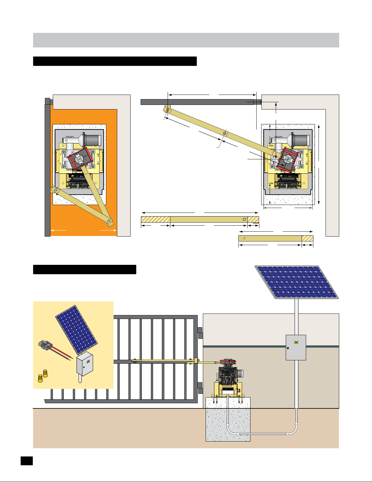
compact installation only
Use compact installation arm measurements when area between the OPEN gate and wall is 20”min to 32”.
DO NOT use these arm measurements for a standard installation. (For standard installation, see page 6)
Gate Bracket Pivot Point
33”
Open Position
Hinge Pivot Point
Closed Position
Illustrations not to scale
LIMIT
LIMIT
CLOSED
OPEN
ERD
MC-200
JOG
Sensitivity
JOG
Motor Controller
Motor
GND
Cell
MATRIX
Photo
LEFT
RIGHT
Jog LT
Edge 1
Edge 2
ON-LINE
UL Entrap
Edge
OverLoad
Jog RT
5
4
1
3
POWER
MAX
2
ERD
12
16
LED ON
Edge
PhotoCell
Limit SW
13
15
14
POWER
POWER/SOLAR
IN
IN
TO MOTOR
CONTROLLER
BATTERY
BATTERY
BATTERY
MATRIX 1
PRIMARY
BACK-UP MODE
GATE
LEAVE
MAGLOCK
CLOSED
DELAY
OPEN
OPEN
PACK
IN
LEAVE
OPEN
MADE in USA
MAG
RIGHT
LEFT
OPEN
1 TIME
OFF
2Sec1.5Sec
LOCK
COM
NC
AUTOMATIC OPEN/CLOSE CONTROLS
Tamper NO
ANTI
GATE
SAFETYCENTEREXIT
TAILGATE
COM
TAMPER
GND
EXIT
OFFON
Tamper IN
CENTER
PHOTOCELL
UL
EDGE 1
SAFETY
MIN
MAX
OFF
ENTRAP
EDGE 2
CLOSE TIMER
ID PLUG
PARTIAL
MOTOR MOTION
ERROR
OPEN
ID
PLUG
UL ALARM 12V
ALARM RET
RESET
OPEN
STOPCLOSE
GND
POSITION
RECORDER
REVERSE SENSITIVITY
MAX
12VDC
GATE SPEED
MOTOR OVERLOAD
GND
OBD PORT
OPEN
BLACK BOX
GATE
MIN
NO LIMIT SWITCH /
COM
STATUS
CLAMP SLIPPING
24VDC
MAX
CLOSE
GND
LIMIT
BATTERY
SWITCH
ON-LINE
IN USE
MOTOR
ON-LINE
POWER
PRIMARY
SEC
GATE
GATE
24V
GND
PHOTOCELL
GND
STRIKE
GND
KEYPAD / RDR
GND
FIRE DEPT
GND
MAX OPEN
GND
RADIO SIG.
RADIO GND
OPEN
STOP
CLOSE
COM
GATE DISABLE
(+)
GND
(-)
(+)
GND
(-)
www.max.us.com
Made in USA
Wall
Entrapment Area
20”min to 32”
It is necessary to protect against the entrapment
that could occur with this type of installation.
(See entrapment protection on page 13)
solar - Optional
Refer to Solar application guide.
MAX Solar Power Kit: MUST be used
when using solar power. Sold separately.
MAX
Solar Panel
24 Volt
Solar
Power
Kit
Long Arm
23”
Arm Elbow Pivot Point
25.5”
Operator Pivot Point
Cut the standard arms down to
meet the shorter measurements.
36”
Long ArmCut Cut
10” 22”
Solar Panel: must be mounted facing
south. It must get full sunlight throughout
the day, NO shadow obstructions.
Short Arm
26.5”
8”
8”
4”
Short Arm
20”
24”
Motor
OverLoad
ERD
12
MATRIX 1
MADE in USA
AUTOMATIC OPEN/CLOSE CONTROLS
EXIT
CENTER
SAFETY
ID
PLUG
12VDC
GND
24VDC
GND
RADIO SIG.
RADIO GND
ERD
JOG
Sensitivity
JOG
LEFT
RIGHT
5
4
3
MAX
16
LED ON
13
15
14
POWER/SOLAR
IN
BATTERY
BATTERY
BACK-UP MODE
LEAVE
CLOSED
IN
LEAVE
OPEN
OPEN
1 TIME
ANTI
TAILGATE
OFFON
MIN
MAX
OFF
CLOSE TIMER
PARTIAL
OPEN
POSITION
RECORDER
MAX
GATE SPEED
OBD PORT
BLACK BOX
MIN
MAX
PHOTOCELL
STRIKE
GND
KEYPAD / RDR
GND
FIRE DEPT
GND
MAX OPEN
GND
www.max.us.com
18.3”
LIMIT
LIMIT
CLOSED
OPEN
GND
Cell
MATRIX
Photo
Jog LT
Edge 1
Edge 2
ON-LINE
UL Entrap
Edge
Jog RT
1
2
Edge
PhotoCell
Limit SW
POWER
IN
TO MOTOR
CONTROLLER
BATTERY
PRIMARY
GATE
MAGLOCK
DELAY
OPEN
OPEN
PACK
MAG
RIGHT
LEFT
OFF
2Sec1.5Sec
LOCK
GATE
SAFETYCENTEREXIT
TAMPER
UL
ENTRAP
MOTOR MOTION
UL ALARM 12V
OPEN
STOPCLOSE
REVERSE SENSITIVITY
MOTOR OVERLOAD
GATE
NO LIMIT SWITCH /
STATUS
CLAMP SLIPPING
LIMIT
SWITCH
ON-LINE
MOTOR
ON-LINE
PRIMARY
SEC
GATE
GATE
GND
OPEN
STOP
CLOSE
COM
GATE DISABLE
(+)
GND
(-)
(+)
GND
(-)
Made in USA
MC-200
Motor Controller
POWER
COM
NC
Tamper NO
COM
GND
Tamper IN
PHOTOCELL
EDGE 1
EDGE 2
ID PLUG
ERROR
ALARM RET
RESET
GND
OPEN
COM
CLOSE
BATTERY
IN USE
POWER
24V
GND
Cut
MAX Solar Kit
30”
4”
12
Power/Solar
Connector
Wire
Nuts
In
PRIMARY
BATTERY
MATRIX 1
GATE
BACK-UP MODE
LEAVE
MAGLOCK
CLOSED
DELAY
OPEN
OPEN
LEAVE
OPEN
MADE in USA
MAG
RIGHT
LEFT
OPEN
1 TIME
OFF
2Sec1.5Sec
LOCK
COM
NC
AUTOMATIC OPEN/CLOSE CONTROLS
Tamper NO
ANTI
GATE
SAFETYCENTEREXIT
TAILGATE
COM
TAMPER
GND
BOARD
EXIT
OFFON
Tamper IN
MATRIX
CENTER
RS-485 (+) -
PHOTOCELL
RS-485 (-) -
PWR 24V -
UL
EDGE 1
SAFETY
MIN
MAX
OFF
ENTRAP
EDGE 2
GND -
CLOSE TIMER
ID PLUG
PARTIAL
MOTOR MOTION
ERROR
s
Solar Panel
Electronic
Box
OPEN
ID
INPUTS
PACK
SWITCH
Power In
MOTOR
MOTOR
PLUG
BATTERY
ALARM
LIMIT
UL ALARM 12V
ALARM RET
RESET
OPEN
STOP CLOSE
POSITION
GND
RECORDER
REVERSE SENSITIVITY
MAX
12VDC
GATE SPEED
MOTOR OVERLOAD
GND
OBD PORT
OPEN
BLACK BOX
GATE
MIN
NO LIMIT SWITCH /
COM
STATUS
24VDC
CLAMP SLIPPING
MAX
CLOSE
GND
LIMIT
BATTERY
SWITCH
ON-LINE
IN USE
MOTOR
ON-LINE
POWER
PRIMARY
SEC
GATE
GATE
24V
GND
PHOTOCELL
GND
STRIKE
GND
KEYPAD / RDR
GND
FIRE DEPT
GND
MAX OPEN
GND
RADIO SIG.
RADIO GND
OPEN
STOP
CLOSE
COM
GATE DISABLE
(+)
GND
(-)
(+)
GND
(-)
MAX BC-7
Battery Voltage
Battery Module
EF1/2
ON/OFF
Replace
TEST
Battery IN
Battery
Battery
Battery
Error
Solar Panel
Electronics
Box
Page 15
installation
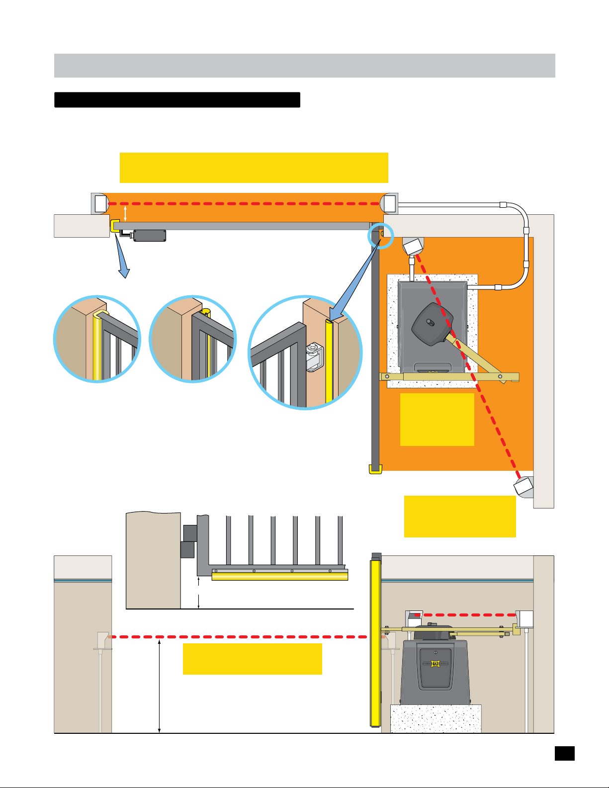
entrapment protection
Install photocells and/or sensing edges to help protect against entrapment during cycling of the gate (entrapment protection).
ONE entrapment protection sensor MUST be installed and connected to “Edge 1 CLOSING direction” on MC-200 motor
controller or operator will NOT function. Entrapment protection sensors MUST be MONITORED and NORMALLY CLOSED (N.C.).
IMPORTANT: Sensing edges MUST be Monitored 10K Normally
Closed Type and a GEM-104 module MUST be installed.
Top View
CLOSING direction photocell to
MC-200 EDGE 1 input, Monitored.
Normally CLOSED (N.C.)
Beam: 5” or LESS from CLOSED gate.
Wireless
WIRELESS NOTE: Refer to the instruction sheet that
Module
comes with the wireless module for wiring and
mounting instructions when using wireless option.
Cl
osed Gate
OPENING/CLOSING
Two Sided 10K Sensing Edge
to Edge 2 or Photo Cell input
MC-200 Edge 2 or Photo Cell input
CLOSING ONLY
10K Sensing Edge
MC-200 Edge 1 input
Closed Gate
One Sided
See pages 17-18 for wiring
instructions.
Dual Gate Operators NOTE: Run EACH entrapment
protection sensor to each corresponding GATE
OPERATOR’S MC-200 motor controller. See page 9.
Entrapment Area
Gate Closed
Hinge AreaEnd of Gate Options
Closed Gate
The hinge area may need protection
against entrapment. MAX 10K mini
sensing edge works well in this area.
(OPEN/CLOSE direction, MC-200
Edge 2 or Photo Cell input)
Bottom of Gate
Conduit
Gate Open
OPENING/CLOSING or
Closing ONLY 10K (N.C.)
Sensing Edge
Max 10K Mini Sensing Edge (N.C.)
Area
Entrapment
IMPORTANT:
Photocells MUST
be in alignment
or fault will occur.
Normally CLOSED (N.C.)
OPENING direction Photocell
IMPORTANT: Photocells
MUST be Monitored
Normally Closed Type.
Side View
6” or More
CLOSING direction Photocell
IMPORTANT: Photocells MUST
Beam Height:
21” Normal
27.5” Max.
be in alignment or fault will occur.
OPEN/CLOSE Sensing Edge on Bottom of Gate: If
the bottom of gate is 6” or higher above the ground,
then a 10K sensing edge should be installed.
Entrapment Protection
10K Sensing Edge,
Install along entire
edge of gate.
OPENING direction Photocell,
Install just above gate operator.
Gate Open
13
Page 16
in-ground loops
T
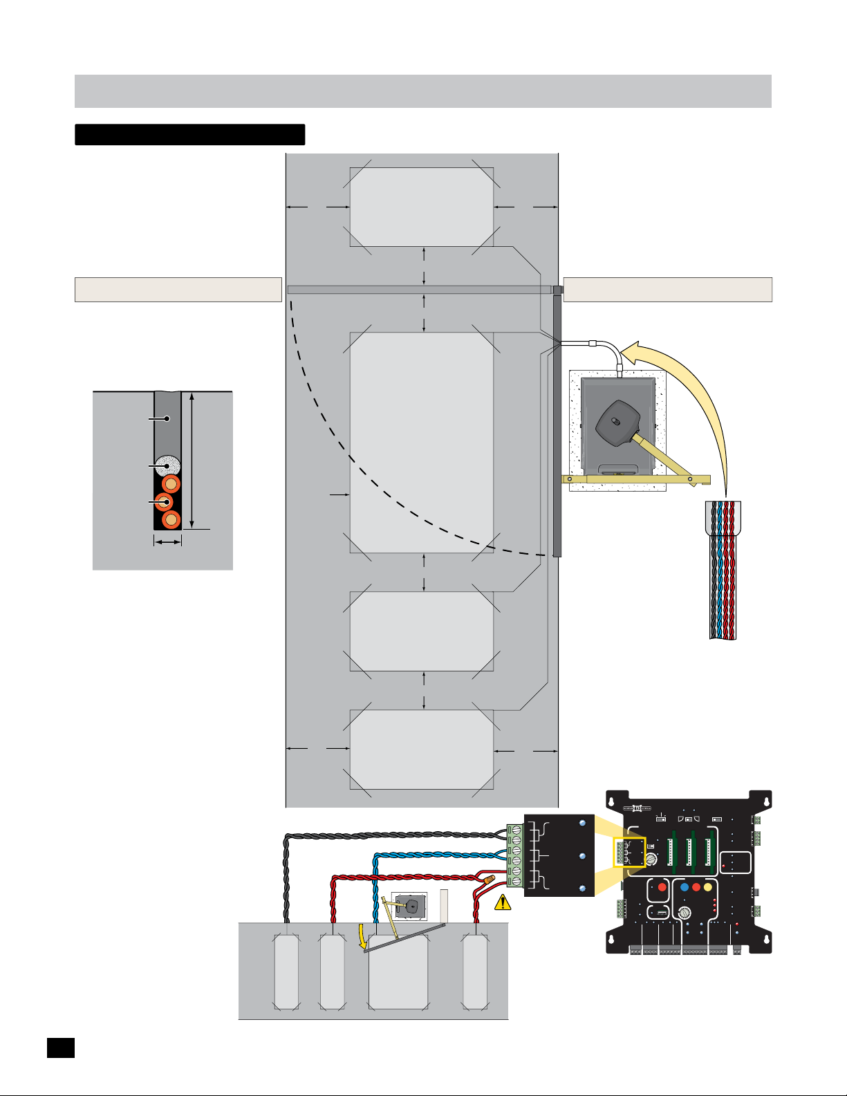
Install in-ground loops to help
protect vehicles from a moving
gate. See pages 25 & 29 for
wiring instructions.
Outside Property
Illustration not to scale
installation
4 ft
Safety
Loop
4 ft
4 ft
Refer to loop maunufacturer’s
instructions to determine specific
loop dimensions.
It is recommended that a
licenced installer perform
this work.
Inside Property
Side View of
Saw Cut
Sealant
Backer Rod
Loop Wire
1/4” Saw Cut
Pavement
Safety Loops
Are placed on each side of the gate to prevent
the gate from closing on a vehicle in it’s path.
They will stop or reverse the cycling of the
gate while a vehicle is in or near the gate’s
pathway.
Center Loop
Will ONLY HOLD the gate in the Full Open
Position when a vehicle is on the center loop.
However, it WILL NOT stop or reverse the
gate once it starts to close.
Exit Loop
Automatically opens the gate for exiting
vehicles without having to use a radio
transmitter (remote control). The exit loop
can be placed a minimum of 4 feet away from
the safety loop or far enough away from the
gate so it has opened by the time the vehicle
approaches it.
1 1/2”
Typical
Inside Property
Saw Cut
4 ft
EXIT LOOP
Lead Wires
SAFETY LOOP
4 ft
Center
Loop
4 ft
Safety
Loop
4 ft min.
Exit
Loop
CENTER LOOP
4 ft
Safety loops need
to be wired in series.
Outside Property
SAFETY LOOP
Lead Wires
Lead Wires
EXIT
CENTER
SAFETY
Conduit
Loop lead wires are
twisted 6 twists per
foot minimum inside
conduit.
Matrix 1 Wiring
BATTERY
MATRIX 1
MADE in USA
AUTOMATIC OPEN/CLOSE CONTROLS
EXIT
CENTER
SAFETY
ID
PLUG
12VDC
GND
24VDC
GND
RADIO SIG.
RADIO GND
ANTI
TAILGATE
MIN
CLOSE TIMER
FIRE DEPT
BACK-UP MODE
LEAVE
OPEN
OFFON
MAX
OFF
POSITION
RECORDER
OBD PORT
BLACK BOX
GND
MAX OPEN
PRIMARY
GATE
LEAVE
CLOSED
OPEN
OPEN
OPEN
RIGHT
LEFT
1 TIME
SAFETYCENTEREXIT
PARTIAL
MOTOR MOTION
OPEN
OPEN
STOP CLOSE
REVERSE SENSITIVITY
MAX
GATE SPEED
MOTOR OVERLOAD
MIN
NO LIMIT SWITCH /
CLAMP SLIPPING
MAX
LIMIT
SWITCH
ON-LINE
MOTOR
ON-LINE
PRIMARY
SEC
GATE
GATE
PHOTOCELL
GND
STRIKE
GND
KEYPAD / RDR
GND
GND
(+)
GND
(-)
(+)
GND
(-)
MAGLOCK
DELAY
MAG
OFF
2Sec1.5Sec
LOCK
COM
NC
Tamper NO
GATE
COM
TAMPER
GND
Tamper IN
PHOTOCELL
UL
EDGE 1
ENTRAP
EDGE 2
ID PLUG
ERROR
UL ALARM 12V
ALARM RET
RESET
GND
OPEN
GATE
COM
STATUS
CLOSE
BATTERY
IN USE
POWER
24V
GND
OPEN
STOP
CLOSE
COM
GATE DISABLE
14
Page 17
installation
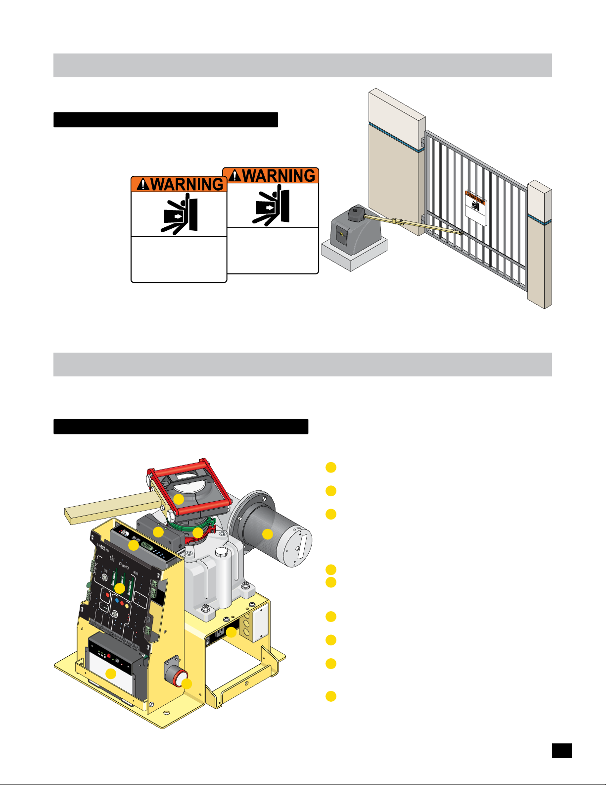
install warning signs
A minimum of two (2) WARNING SIGNS shall be installed,
one on each side of the gate where easily visible.
Moving Gate Can Cause
Moving Gate Can Cause
Serious Injury or Death
KEEP CLEAR! Gate may move at any time
without prior warning.
Do not let children operate the gate or play
in the gate area.
This entrance is for vehicles only.
Pedestrians must use separate entrance.
Serious Injury or Death
KEEP CLEAR! Gate may move at any time
without prior warning.
Do not let children operate the gate or play
in the gate area.
This entrance is for vehicles only.
Pedestrians must use separate entrance.
M
o
vi
Seri
ng G
KE
ous
EP
w
at
it
C
h
L
o
e Can Caus
EAR
u
I
D
t
nj
p
o
r
!
n
io
ury or De
in
o
r
G
t
le
w
t
at
h
a
e
e
t
r
c
n
g
T
m
h
in
a
h
ildr
a
t
g
is
e
y
.
Pe
e
a
e
m
n
r
n
o
e
d
t
r
o
v
a
e
e
a
e
p
.
s
n
at
e
t
a
c
r
r
ia
t
e
a
a
h
t
ns
is
e
n
y
t
f
h
m
o
t
e
r
im
us
v
g
e
e
t
ate
h
u
i
s
c
e
le
o
r
s
s
p
e
o
la
p
nly
a
y
r
a
.
te
e
n
t
r
a
n
c
e.
Wiring operator
Check with local building department prior to installing any permanent wiring on this gate operator. Make sure all wiring
complies with local code requirements.
Gate Operator Overview
1
MAX Megatron Toroid Box: AC power management for the
AC input power to the gate operator. See pages 19, 20 & 23.
2
2
O
Mo
v
er
t
or
L
oa
d
E
Sen
E
RD
RD
s
i
ti
v
it
y
5
1
2
4
1
3
3
1
4
1
1
5
6
MATR
I
X
1
M
A
B
DE
A
BAC
TT
in
USA
ER
K-
Y
U
P
MO
LE
LE
DE
A
A
V
C
V
E
L
E
OPE
OS
ED
N
P
RI
MA
OP
E
R
N
G
AUT
1 TI
ATE
M
E
OMA
O
P
E
N
L
T
E
F
IC
T
OPE
A
OP
N
EX
TA
T
R
I
T
I
IG
I
E
LG
N
A
/
T
CL
E
D
ON
OSE
R
IX
E
BOA
OF
X
R
C
I
F
CON
T
T
EN
PWR 24V -
TER
MA
T
RS-485 (-) -
ROL
RS-485 (+) -
E
N
GND -
T
E
R
SA
FE
T
Y
M
I
N
O
M
F
A
F
C
X
LO
S
E
T
ID
I
M
ER
P
LU
G
PA
R
TI
AL
O
PE
9
N
1
2
V
DC
GN
D
MOT
P
O
OS
R MO
I
R
T
EC
I
2
O
4
V
DC
GN
D
.
IG
S
IO
D
A
R
T
N
O
I
ON
R
DE
R
O
B
D
PO
BL
O
P
ACK BO
R
E
T
N
M
A
X
X
S
T
OP C
G
A
T
E SPEE
R
L
E
M
V
O
I
ER
N
S
D
E
S
M
EN
A
X
S
I
M
D
N
G
IO
D
A
R
TI
OTOR
V
I
O
V
T
ER
N
LO
P
O
LI
A
E
N
M
C
I
T
LA
E
SW
M
D
P
I
T
S
C
LI
H
OP
DR
P
P
I
IRE
NG
X
R
ND
F
L
E
IM
A
D
G
SW
IT
LL
D /
M
IT
O
CH
E
N
GN
L
IN
TRIK
PA
E
ND
S
D
MO
TOC
EY
G
TOR
K
O
O
P
N
RI
-
GN
D
LIN
H
M
A
R
E
P
GA
Y
TE
GN
)
D
S
(+
EC
GN
)
GA
TE
(-
)
D
(+
N
GN
)
E
(-
OP
TOP
S
Ba
tt
e
ry Vo
E
l
t
ag
1
e
/
2
F
ON/
MAX BC
O
F
Batte
F
B
at
R
tery
e
r
y
p
la
Mo
c
-
Ba
e
7
d
tte
u
le
r
T
y
E
S
T
B
a
tter
B
a
y
tte
r
y
I
N
Er
ro
r
6
8
J
OG
M
L
E
AX
LE
F
D
O
T
N
J
OG
RI
G
H
T
LT
g
o
RT
J
D
g
o
N
1
J
G
e
2
g
d
e
g
E
to
d
o
E
h
l
l
P
e
C
5
M
A
O
TR
N
-
I
LI
X
N
E
E
L
d
i
m
g
1
e
i
t
S
W
M
U
2
L
En
o
tr
E
a
d
p
g
e
Ph
P
o
t
O
o
C
W
e
l
Y
N
HT
S
S
AFETYC
M
R
LA
A
S
E
T
Y
D
/
S
E
LOS
C
OM
AT
C
G
l
M
A
GL
O
DELA
CK
OF
F
Y
1.5S
ec
2S
ec
M
A
G
LO
CK
C
OM
N
C
G
A
TE
TA
M
Tampe
H
PE
C
T
I
R
W
S
T
I
r
M
I
L
K
NO
C
PA
RY
E
C
T
T
OM
A
B
S
T
G
PU
T
N
N
I
a
R
D
m
O
T
p
MO
e
r
IN
In
wer
o
P
P
H
U
O
L
TO
C
ELL
OR
E
N
T
R
E
AP
MOT
D
G
E
1
E
D
G
E
2
ID P
LU
G
ER
R
O
R
U
L
A
LAR
A
M
LAR
12
V
M
R
E
RE
T
SET
G
N
GA
D
T
E
T
A
T
U
S
OP
E
N
C
O
M
C
LO
S
E
E
L
B
A
B
T
TER
A
S
Y
I
N
U
DI
SE
E
P
OW
ER
V
ND
24
G
7
t
MC-
or
C
ont
200
roll
e
ER
r
n
io
t
c
e
t
o
r
p
e
h
d
t
e
h
u
t
in
t
wi
n
.
o
ly
c
n
se
r
o
u
o
f
F
f
ce
s
:
o
s
la
a
le
g
p
p
e
NG
in
e
r
e
t
r
t
,
n
a
r
n
e
r
l
o
ire
u
d
f
b
c
ARNI
i
o
n
s
n
p
a
st
W
u
f
io
in
e
s
a
n
ct
NT:
yp
e
g
u
e
t
t
E
u
a
r
o
e
q
e
r
i
M
t
p
m
lis
i
t
ris
a
SE
l
sa
u
é
S
I
e
,
ct
r
T
t
ie
a
t
r
d
e
ER
ca
m
V
t
cen
ro
A
e
’in
e
d
mp
yp
s
t
co
e
s
u
q
me
is
r
ê
s.
m
le
e
a
d
n
i
m
o
n
Amp
7
E
1
x
S
FU
n
O
R
3A ma
E
AC
OW
V
P
115
f
f
O
4
3
Release Handle Clamp: Manually move the gate when
handle is raised. See page 41.
3
Audible Alarm: Sounds when there is a problem with cycling
the gate. Push the STOP button on the Matrix 1 or an
externally mounted Alarm Reset button to shut-off alarm.
Alarm can sound every time operator is cycled using ONLY
battery back-up power when turned ON, See page 32.
4
24VDC Brushless Motor (6 million cycles)
5
MAX MC-200 Motor Controller: Manages UL entrapment
protection devices and operator motor reversing ERD
sensitivity adjustment. See pages 19, 20, 22, 25 & 34.
6
MAX BC-7 Battery Module: Battery Back-Up and DC power
management for the gate operator. See next page.
7
Limit Tabs: Adjusts the OPEN and CLOSE gate positions.
See page 35.
8
Limit Switch Box: Contains the limit switches. Gate operator
will NOT function when limit switch box is not connected.
See page 35.
9
Matrix 1: Manages control panel operations. Manages
inputs/outputs, loops and reports problems with gate
operator. See Matrix 1 Section starting on page 24.
15
Page 18
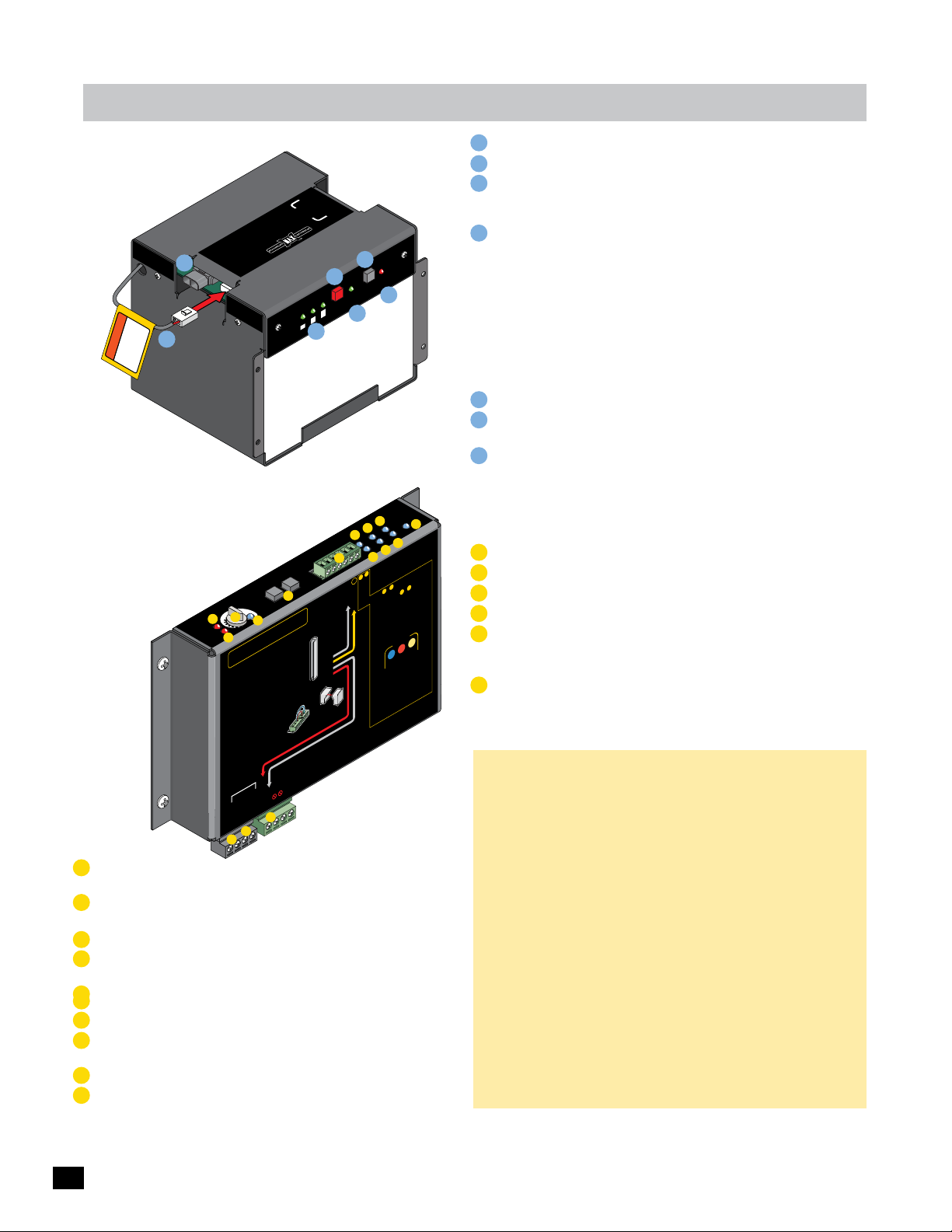
Wiring operator
MAX BC-7 Battery Module
OWER
P
IN
R
O
ry
T
R
E
k
c
MO
LL
Batte
O
Pa
TO
ONTR
C
Max.US.com
w.
ww
Moto
OverLoa
r
WER/SOLA
PO
A
d
ERD
ERD
Sensitivity
MC-200 Swing
R
IN
Y
R
ATTE
IN
B
BATTERY
IN
JOG
RIGHT
JOG
LEFT
E
N
O
MAX
4
3
5
LED
C
16
D
15
14
13
12
B
See installation instructions
ir la notice d’installation.
Vo
N:
AUTION:
C
TTENTIO
A
A sensor
•
operator
Wire NORMAL
•
MONI
operato
are used
Reversing Edge and/or Photo Cell can
•
be wired to
MC-200 PWR 12V
•
power
UNUSED
•
JUMPERED
MA
PWR 24V -
O
EDGE 1
Entrapment Protection
be wired to
(N.C.)
function.
Sensor Guideline
T
MUST
ONLY, to each
WILL NO
LY CLOSED
D sensors
RE
TO
MC-200 when dual operators
r’s
3 Inputs
.
of the
ANY
MUST be used to
sensors.
RED
MUST remain
MONITO
inputs
or fault will occur.
MC-200
ONLY power entrapment protection
PWR 12V
sensors with MC-200 PWR 12
RS-485 (+) -
TRIX 1
GND
RS-485 (-) -
-
-
-
-
GND -
P
N
s
.
PWR 12
ALARM
2
Battery Voltage
1/
E
3
Jog LT
.
or
Monitored
Photo
Cell
3
2
1
GND
MUST
V
LIMIT
SWITCH
F
2
e 1
GND
Jog RT
Monitored
Reversin
Edge
OR
be used
BATTER
ACK
P
4
ON/OF
Batt
o
ot
Edge
Edg
V
Y
Replac
F
Battery
ery
5
G
X
MATRI
Cell
ON-LINE
Ph
F
1
-
-
-
GND
Jog RT
Jog LT
g
R
TO
MO
INPUTS
MAX BC-7
6
Battery Module
N
I
Battery
Error
TEST
e
Battery
7
ntroller
MC-20
L
Motor Co
POWER
I
UL Entrap
e
g
Ed
PhotoCell
1
ge
2
Ed
J
SW
it
Lim
H
MUST jumper
Entrapment Protectio
3
Inputs:
2
unused inputs
3
2
R sensors
TO
Edge 2
Inputs &
Photo Cell
to MONI
Edge 1
o LEARN inputs & :
T
MONITORED
1.
Any un
wired to inputs BEFORE they can be
learned.
jumpered.
Reversing Edge and/or Ph
2.
be wired to either input 2 or 3.
Press and HOLD th
3.
buttons at the same time on
ntil beep is heard, learn mo
u
OPEN STOP
.
Learn mode lasts for 5 min. indicated
LL be
WI
by beeping
LEDs
MC-200s when dual
4.
TH
ensor on MC-200. LEDs
s
BO
button again within 5 min.
for
STOP
operators are used.
ress
P
5.
to learn sensors and end learn mode,
beeping stops.
Inputs are now
Power In
0
M
K
.
MUST be “LEARNED”
3
be
2
Sensors MUST
uts MUST
p
to Cell ca
used in
o
Matrix
OPEN & ST
e
de begins
ON
MOTOR MOTI
E
CLOS
ach detected
e
WILL
for
ON
.
MONITORED
R
TO
MO
POWER/SOLAR
IN
2
connect to
before use
“BATTERY IN”
1
IMPORTANT
MAX MC-200 Motor Controller
Continued on next 2 pages.
Matrix On Line LED: Gate operator is successfully communicating with
G
Matrix 1 when lit.
H
Limit SW On Line LED: Limit Switch Sensors are successfully
communicating with MC-200 Motor Controller when lit.
Edge 1 LED: Edge 1 sensor has been activated when lit.
I
Edge 2 LED: Edge 2 sensor has been activated when lit. LED will light up
J
during “LEARNING” mode when sensor is connected, see page 18.
Photocell LED: Photocell sensor has been activated when lit. LED will light
K
L
up during “LEARNING” mode when sensor is connected, see page 18.
M
UL Entrap LED: Edge1/Edge2/Photocell inputs have been activated when lit.
N
Power LED: Low voltage power is connected when lit.
RS-485 Input:
O
Wire to Matrix 1 “SEC GATE” for Secondary operator ONLY.
P
24V Power Input: 24V Power for Matrix 1 ONLY.
12V Entrapment Protection Sensor Power Out: 12V Power that ALL
Entrapment protection sensors MUST use PWR 12V power.
Factory wired for Primary operator.
1
BATTERY Plug: MUST be plugged into BATTERY IN port Before use.
POWER/SOLAR IN Port: MAX Megatron Toroid box connection.
2
3
Battery Voltage LEDs: Show amount of battery power available.
LEDs are always ON when using AC power. Test battery button must be
pressed to show battery power when using battery power ONLY.
4
ON/OFF Battery Button:
IMPORTANT: Battery power automatically turns ON when MAX Megatron
Toroid Box AC POWER Switch is turned ON.
To turn OFF ALL POWER to operator:
1. Turn OFF AC POWER Switch on MAX Megatron Toroid Box.
Battery power remains ON.
2. WAIT for 15 seconds.
3. Press and HOLD (approx. 5 seconds) the RED ON/OFF BATTERY
button until MAX BC-7 LEDs turn ON, then release button.
LEDs will turn OFF.
5
Replace Battery LED: Replace battery when lit.
6
TEST Battery Button: Press to show amount of battery power available when
using battery power ONLY (Battery voltage LEDs will light respectively).
Battery IN Error LED: Lights when there is a battery connection problem.
7
Make sure battery plug #1 is plugged into BATTERY IN port or there is no
damaged or loose wires.
n
be
n
OP
1
.
ON
be
A
MOTOR OVERLOAD LED: Excessive current being drawn by motor when lit.
B
ERD LED: ERD sensor has been activated when lit.
C
ERD Sensitivity Knob: 16 selectable sensitivity settings of ERD sensor.
D
ERD Sensitivity LED: MAX sensitivity reached when lit.
E
Jog LEFT/RIGHT Buttons:
Push and HOLD buttons accordingly to move the gate (release the button to
stop gate). WARNING: Avoid moving gate while using Jog buttons.
INPUTS:
F
Jog LT/RT inputs: Can connect to an External Open/Close Key switch.
Connect a single key switch to control dual gate operators, See page 34.
GND input: Low Voltage Common connection.
Edge 1-MONITORED CLOSING direction ONLY input: Connects to a
NORMALLY CLOSED (N.C.) Sensing Edge or Photocell.
Closing direction activation: gate will reverse to full open position and
reset close timer.
Opening direction activation: gate will NOT be monitored during
opening cycle.
Edge 2-LEARNED MONITORED OPENING/CLOSING direction input:
Connects to a NORMALLY CLOSED (N.C.) Sensing Edge or Photocell.
Input MUST be “LEARNED” before it can MONITOR a connected sensor
(see page 18).
Closing direction activation: gate will REVERSE to full open position but
will NOT reset close timer. Another command is required for gate to
resume operation.
Opening direction activation: gate will REVERSE 2 inches and STOP.
Another command is required for gate to resume operation.
Photo Cell-LEARNED MONITORED OPENING/CLOSING direction input:
Connects to a NORMALLY CLOSED (N.C.) Sensing Edge or Photocell.
Input MUST be “LEARNED” before it can MONITOR a connected sensor
(see page 18).
Closing direction activation: gate will STOP. Another command is
required for gate to resume operation.
Entrapment Protection Sensor Inputs
Opening direction activation: gate will STOP. Another command is
required for gate to resume operation.
DUAL GATE OPERATORS NOTE: Connect EACH photocell/sensing
edge to the corresponding gate operator’s MC-200. See page 9.
16
Page 19
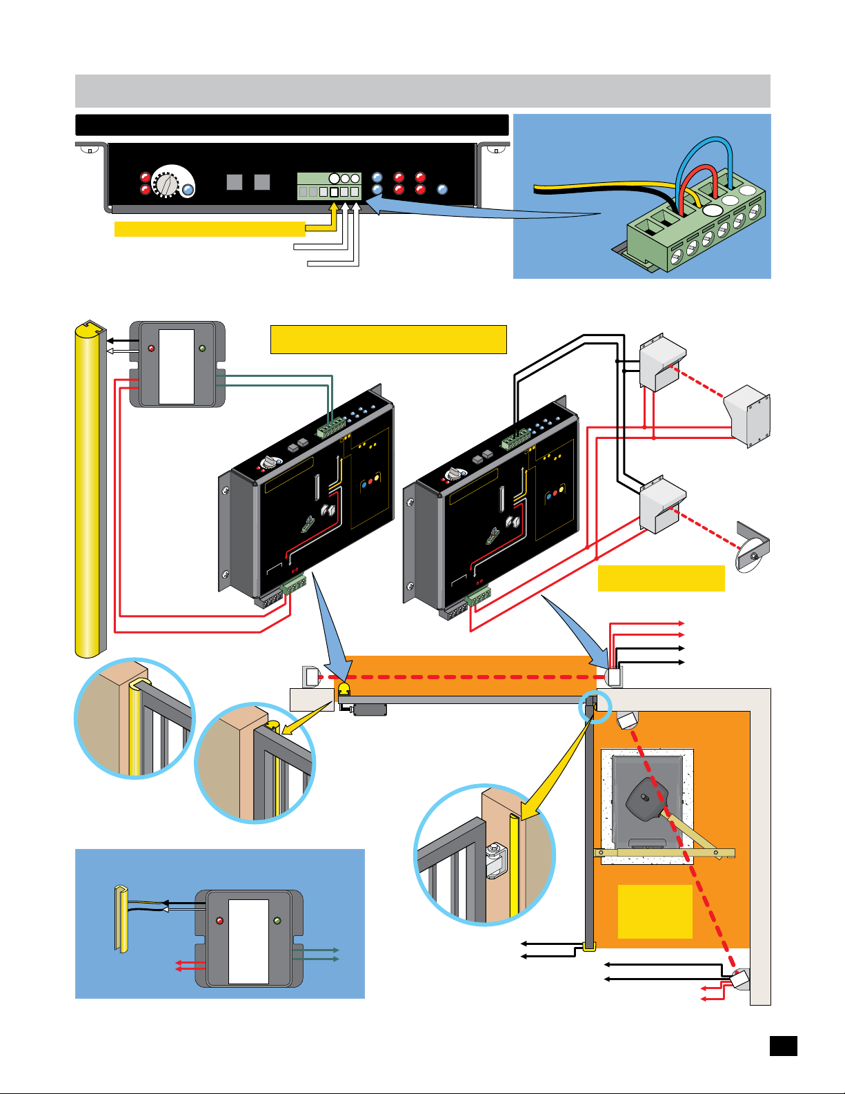
Wiring operator
entrapment protection wiring
Motor
OverLoad
ERD
ERD
Sensitivity
12
13
14
JOG
JOG
LEFT
5
4
3
MAX
16
LED ON
15
RIGHT
GND
MATRIX
Cell
Jog LT
Photo
Edge 1
Edge 2
ON-LINE
3
Limit SW
Edge
1
2
Edge
Jog RT
2
1
MC-200
Motor Controller
UL Entrap
POWER
PhotoCell
Jumper UNUSED Entrapment Protection Inputs
or a fault will occur.
Normally Closed (N.C.)
Sensor Wire
GN
D
EDGE 1: MONITORED CLOSE ONLY
Edge 2: LEARNED MONITORED OPEN/CLOSE
Photo Cell: LEARNED MONITORED OPEN/CLOSE
Example: Inputs 2 & 3
are NOT used and MUST
be jumpered to GND.
Typical Wiring For:
a 10K Normally Closed (N.C.) Sensing Edge ...... AND/OR ........ a Normally Closed (N.C.) Photo Cell
10K Edge
Normally
Closed
GEM - 104
ON = Obstruction
BLINKING = Fault
MON.
PWR
SAFETY
INPUT
GEM-104
EDGE 1 (N.C.)
CLOSING
Direction
ONLY
One Sided Edge
PWR 12V
Polarity does NOT matter
GND
End of Gate
Closed Gate
OPENING/CLOSING
Two Sided 10K Sensing Edge
to Edge 2 or Photo Cell input
(to wireless module when
using Wireless Option).
To
Normally Closed
10K Sensing Edge
To MC-200 Power
(Polarity does NOT matter)
DUAL GATE OPERATORS NOTE: Connect EACH photocell/sensing edge to the corresponding gate operator. See page 9.
Options
Gate Edge Module (GEM-104)
MUST be used with EACH Normally Closed
10K type Sensing Edge.
10K Edge
Normally
Closed
GEM - 104
IMPORTANT Sensing devices MUST be powered by
MC-200 or they will NOT be MONITORED.
GND (C)
r
le
MC-200
Control
R
r
E
W
Moto
PO
Entrap
UL
e
ell
Edg
hotoC
NE
I
l
P
1
l
L
MATRIX
e
o
N-
Ce
2
O
ot
2
Edg
e
Ph
1
W
S
e
D
Motor
verLoad
O
ON = Obstruction
BLINKING = Fault
MON.
PWR
SAFETY
INPUT
vity
i
ERD
4
3
5
Sensit
3
2
1
1
ERD
AUTION:
C
TTENTION:
A
Entrapment Prot
MC-200 Swing
A sensor
•
operator
NORMALLY
re
Wi
•
MONITO
operator
are used.
Rever
red to
•
be wi
C-200 PWR 12V
M
er
•
w
o
p
SED
U
N
U
P
•
M
U
J
TRIX
MA
PWR 24V -
GND -
Closed Gate
T
OG
F
J
E
L
MAX
LED ON
6
1
15
14
nstallation instructions
notice d’
See i
ir la
Vo
be wired to
function.
Sensor Guidelines
T
UST
M
NO
CLOSED
WILL
sensors
when dual operators
D
00
RE
MC-2
’s
of the
ng Edge and/or Photo
ANY
MUST
si
sensors.
D
RE
TO
MUST
s
MONI
ut
p
ault will occu
in
or f
RED
E
O
PWR 12V
se
1
RS-485 (+) -
GND
RS-485 (-) -
-
-
Edg
Edg
GN
RT
og
J
g LT
Jo
G
O
J
GHT
RI
-
-
Jog RT
Jog LT
.
.
nstallation
i
n
ctio
e
Monitored
or
Reversing
EDGE 1
Edge
)
C.
.
OR
(N
d
to each
,
LY
ON
Monitore
Photo
Cell can
Cell
Inputs.
3
3
2
be used to
1
GN
D
be used
ST
r.
U
remain
M
V
n
12
o
ti
tec
0 PWR
0
pro
V
t
-2
n
12
C
M
WR
apme
P
MO
tr
00
P
-2
IN
Y
C
R
M
wer en
TE
o
th
p
i
BAT
CK
w
LY
PA
N
ors
LIMIT
H
ns
C
IT
W
S
M
R
A
L
A
-
-
CLOSING ONLY
One Sided
10K Sensing Edge
to EDGE 1 input
(to wireless module
when using Wireless
Option).
To MC-200
GND
To MC-200
Edge 1, Edge 2,
or Photo Cell
er
Limit
mp
”
MUST ju
D
Entrapment Protection
inputs
3
Inputs:
2
unused
1
-
MUST be “LEARNE
ors.
3
3
be
T
& :
2
2
can be
R sens
be
s MUS
ST
Edge 2
puts &
puts
they
In
MU
Photo Cell
MONITO
GND
Sensor
D
to
ARN in
EFORE
Edge 1
Cell can
o LE
TORE
T
NI
o inputs B
MO
OP
ny unused inputs
1.
A
x 1
and/or Photo
wired t
N & ST
ns.
E
ed.
input 2 or 3.
earned.
Matri
OP
l
on
umper
the
j
versing Edge
d to either
Re
2.
ON
s and HOLD
I
be wire
OT
M
heard, learn mode begi
R
Pres
TO
3.
O
M
buttons at the same time
CLOSE
until beep is
in. indicated
m
ted
N
for 5
OPEN STOP
be O
L
L
r each detec
WI
fo
ON
LEDs
be
Learn mode lasts
5 min.
when dual
WILL
s
by beeping.
-200s
D
LE
MC
4.
on again within
OTH
sensor on MC-200.
B
s are used.
.
butt
D
and end learn mode,
for
OP
ST
s
operator
.
Pres
MONITORE
5.
to learn sensors
e now
beeping stops
nputs ar
I
MOTOR
Power In
TOR
TS
U
Wireless
Module
Wireless Option: See separate wiring instruction sheet.
NOTE: see next page
for sensor model #s
and Learning Edge 2
and Photo Cell inputs.
2
1
ge
D
T
GN
g R
Jo
og LT
J
T
H
JOG
IG
R
OG
J
LEFT
y
t
X
N
A
ERD
M
D O
nsitivi
E
4
e
3
5
L
S
r
d
o
oa
Mot
verL
O
D
ER
MC-200 Swing
AUTIO
C
AT
A
•
o
Wire
•
MO
ope
are
Re
•
be wi
MC
•
p
U
•
J
MA
PWR 24V -
1
12
ENT
T
sensor
er
p
NI
v
-
w
o
U
N
M
U
GND -
16
15
14
3
S
:
N
N:
O
I
Entrapm
nsor Guidelines
Se
MU
WI
ator
RMAL
NO
ORED
T
MC
’s
ator
r
d.
e
s
u
E
ng
i
s
er
to
ed
r
WR
P
NI
200
MO
er
n
i
SED
ED
R
E
P
1
RS-485 (+) -
TRIX
RS-485 (-) -
ee
Vo
S
L NO
L
dg
ANY
T
uts
p
or
nstalla
i
a
r l
i
ent Prot
wi
be
T
T
CLO
LY
or
ens
s
wh
0
20
-
e and/
of the
MU
12V
D
RE
O
MU
lt wi
fau
PWR 12V
GND
-
-
ns.
o
ucti
tr
on.
i
s
at
in
l
l
n
o
ti
nsta
i
’
d
ce
i
ot
n
ion
t
c
oni
e
M
or
1
Reve
DGE
g
E
o
t
Ed
ed
r
)
on.
ti
c
n
OR
N.C.
s
fu
D (
o each
tor
t
E
S
opera
onitor
ONLY,
s
M
o
n dual
e
can
l
Phot
l
Ce
o
Cell
.
hot
P
r
o
Inputs
ed to
3
3
us
2
be
T
.
1
S
s
GN
D
nsor
e
e u
n
i
s
b
T
S
ema
r
ur.
T
c
MU
S
l oc
l
R 12V
PW
o
0
0
pr
2
t
-
1
C
en
R
M
m
W
p
P
ra
t
n
e
200
-
C
M
T
ower
h
p
BAT
wit
LY
PAC
N
T
rs
I
O
M
so
LI
H
n
C
e
IT
s
W
S
M
R
LA
A
-
-
ND
G
PWR 12V
Entrapment Area
Gate Closed
OPENING/CLOSING
10K MAX Mini Sensing Edge
to Edge 2 or Photo Cell input
d Gate
e
Clos
OPENING/CLOSING or
Closing ONLY 10K (N.C.)
ND (C)
G
EDGE 1 (N.C.)
r
le
l
ntro
CLOSING Direction
MC-200
ER
or Co
W
ot
trap
M
PO
En
UL
e
l
l
g
e
Ed
IX
toC
E
ho
TR
N
P
1
-LI
ONL
MA
e
o
g
t
Cell
ON
Pho
ge
Ed
Ed
-
-
-
Jog RT
Jog LT
ored
t
ng
rsi
e
ed
ed
s
n
io
t
ec
t
V
2
TOR
TS
MO
U
P
IN
Y
R
E
K
larity does
Po
Limi
2
1
Edge 2
GND
Edge 1
Po
2
Ed
SW
t
US
M
:
u
s
t
Entrapment Protecti
p
in
3
Inpu
nused
u
MU
3
&
sensors.
2
ITOR
N
nput
Inputs
i
Photo Cell
N
MO
Sensor
R
to
A
ED
s
o LE
TOR
T
I
N
input
unus
y
MO
1.
An
ired to
w
earned.
l
her input
ing Edge
eit
s
jumpered.
er
ev
OL
ed to
R
H
2.
and
be wir
he s
t
at
ess
heard,
Pr
is
ons
3.
OTOR
M
butt
until beep
OPEN
st
mode la
be
Learn
L
beeping.
-200.
C
WIL
M
s
by
-200s w
D
on
LE
MC
4.
used.
OTH
are
sensor
B
s
but
or
for
OP
or
ST
s
operat
es
Pr
ops.
t
5.
s
now
to learn sens
are
beeping
Inputs
er In
w
s
t
s
EF
B
and/or
D
ame
ST
s
ON
on
t
and
s
MO
mper
T ju
ST be
&
2
s
ORE
input
ed
he OPEN
t
time
arn mode
le
N
O
I
T
O
M
P
O
5 min
or
f
eac
or
f
D
LE
hen
again w
end
TOR
I
N
MOTO
NOT
3
MU
Phot
2 or
CLOSE
s
“
t
on
learn mode,
R
A
LE
:
be
ST
can be
hey
MU
s
C
o
3.
&
Matr
indi
.
det
h
L
WIL
dual
hin 5
it
ED.
R
on
”
D
E
N
be
ST
an
c
ell
OP
T
S
x 1
i
gins.
be
cated
ed
t
ec
ON
be
in.
m
matter
Gate Open
To GEM-104
To GEM-104
Sensing Edge
(Hardwired)
Re
cr
Thru-Beam
Y
Power
See next page for a specific
photocell’s N.C.- N.O. input.
Reflective
Beam
IMPORTANT: Photocells MUST
be in alignment or fault will occur.
Polarity does NOT matter
To MC-200 Power
To GND
To Edge 1
NORMALLY CLOSED
CLOSING direction Photocell
Max 10K Mini Sensing Edge (N.C.)
OPENING direction Photocell
Normally CLOSED (N.C.)
IMPORTANT:
Photocells MUST
be in alignment
or fault will occur.
To MC-200 Edge 2 or Photo Cell
To GND
To MC-200 Power
(Polarity does NOT matter)
2
1
Trans
Power
Area
Entrapment
3
Reflector
17
Page 20
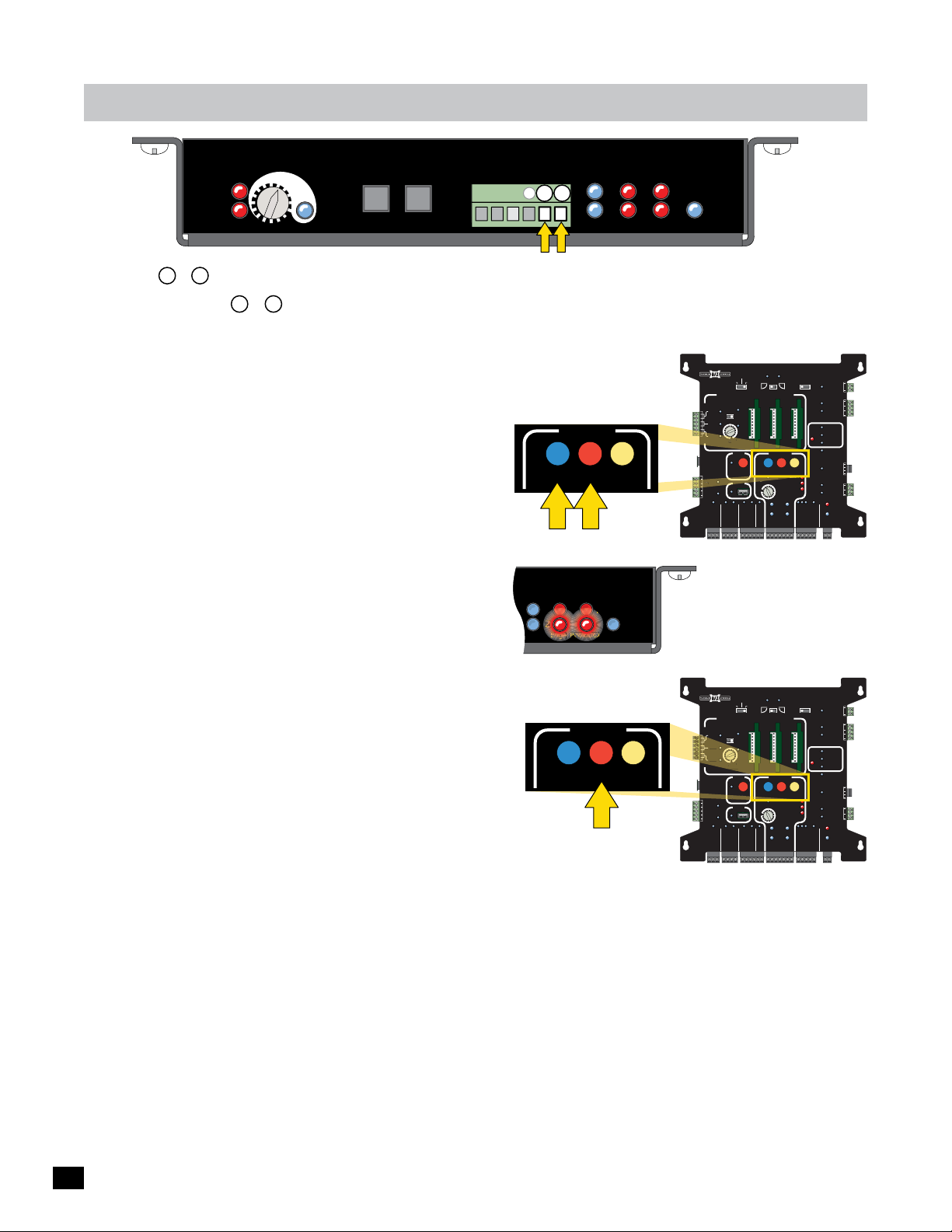
Wiring operator
P
Edge2Edge
2
Edge
2
Edge
P
P
hotoCellPhotoCel
CLOSE TIMER
MAX
MIN
OFF
S
Y
MAX
RECORDER
REVERSE SENSITIVITY
12VDC
GND
C
R
MAXM
F
S
Y
P
Motor
OverLoad
ERD
ERD
Sensitivity
12
13
14
JOG
JOG
LEFT
5
4
3
MAX
16
LED ON
15
RIGHT
GND
Jog LT
Jog RT
1
Edge 1
Edge 2
2 3
MATRIX
Cell
Photo
ON-LINE
Limit SW
1
2
Edge
Edge
MC-200
Motor Controller
UL Entrap
POWER
PhotoCell
EDGE 1 Note: CLOSING direction ONLY.
Inputs & MUST be “LEARNED” to MONITOR OPENING/CLOSING direction sensors.
To LEARN inputs & :
2 3
2 3
1. MONITORED Sensors MUST be wired to inputs BEFORE they can be learned.
Any unused inputs MUST be jumpered, see previous page.
2. A Sensing Edge or Photo Cell can be wired to either input 2 or 3.
3. Press and HOLD the STOP button & then the OPEN button
together on Matrix 1 until beep is heard, learn mode begins.
NOTE: DO NOT press the OPEN button before the
STOP button or learn mode will NOT function.
4. LEDs WILL be ON for each detected sensor on MC-200.
LEDs WILL be ON for BOTH MC-200s when dual operators
Motor
OverLoad
are used. If an LED is not on and it should be, wiring to
sensor is bad, photocells are out of alignment, photocells
ERD
are wired wrong - N.C. or N.O. depending on which
ERD
Sensitivity
12
13
14
JOG
JOG
LEFT
5
4
3
MAX
16
LED ON
15
RIGHT
GND
MATRIX
Cell
Edge 1
1
Edge 2
2 3
Photo
ON-LINE
Jog LT
Jog RT
Limit SW
MOTOR MOTION
OPEN STOP
Motor Controller
UL Entrap
Edge
1
2
Edge
PhotoCell
CLOSE
MC-200
POWER
MATRIX 1
MADE in USA
EXIT
CENTER
SAFETY
AFET
ID
PLUG
12VDC
GND
24VDC
GND
RADIO SIG.
Example shows that sensors
are DETECTED on inputs
Edge 2 and Photo Cell.
photocells are used (see below) or sensor is bad etc. and
must be corrected. When all LEDs are ON that should be ON, proceed to next step.
MOTOR MOTION
5. Press STOP button again within 5 min. to learn sensors and
end learn mode, beeping stops.
OPEN
STOP
CLOSE
Wired Inputs are now MONITORED.
If STOP button is not pressed within 5 min. learn mode terminates.
If no sensors are detected then factory default setting (Edge 2 and
ID
PLUG
12VDC
GND
24VDC
GND
MATRIX 1
MADE in USA
EXIT
CENTER
ENTE
SAFETY
AFET
RADIO SIG.
BATTERY
PRIMARY
BACK-UP MODE
GATE
LEAVE
CLOSED
OPEN
OPEN
LEAVE
LEFT
1 TIME
OPEN
AUTOMATIC OPEN/CLOSE CONTROLS
ANTI
TAILGATE
OFFON
MIN
MAX
OFF
CLOSE TIMER
PARTIAL
MOTOR MOTION
OPEN
OPEN
POSITION
RECORDER
MAX
GATE SPEED
OBD PORT
BLACK BOX
MIN
MAX
PRIMARY
GATE
PHOTOCELL
GND
STRIKE
GND
KEYPAD / RDR
GND
FIRE DEPT
GND
MAX OPEN
GND
RADIO GND
AUTOMATIC OPEN/CLOSE CONTROLS
CLOSE TIMER
RADIO GND
TAILGATE
MIN
FIRE DEPT
ANTI
IN
BACK-UP MODE
LEAVE
OPEN
OFFON
MAX
OFF
OF
POSITION
RECORDER
OBD PORT
BLACK BOX
GND
MAX OPEN
(+)
BATTERY
PRIMARY
GATE
LEAVE
CLOSED
OPEN
OPEN
LEFT
1 TIME
PARTIAL
MOTOR MOTION
OPEN
OPEN
OSITION
MAX
GATE SPEED
MIN
MAX
PRIMARY
GATE
PHOTOCELL
GND
STRIKE
GND
KEYPAD / RDR
GND
GND
(+)
OPEN
RIGHT
LIMIT
SWITCH
ON-LINE
MOTOR
ON-LINE
GND
(-)
OPEN
RIGHT
LIMIT
SWITCH
ON-LINE
MOTOR
ON-LINE
GND
(-)
SAFETYCENTEREXIT
STOP CLOSE
REVERSE SENSITIVITY
MOTOR OVERLOAD
NO LIMIT SWITCH /
CLAMP SLIPPING
SEC
GATE
(+)
SAFETYCENTEREXIT
STOP CLOSE
REVERSE SENSITIVITY
MOTOR OVERLOAD
NO LIMIT SWITCH /
CLAMP SLIPPING
SEC
GATE
(+)
MAGLOCK
DELAY
MAG
OFF
2Sec1.5Sec
LOCK
COM
NC
Tamper NO
GATE
COM
TAMPER
GND
Tamper IN
PHOTOCELL
UL
EDGE 1
ENTRAP
EDGE 2
ID PLUG
ERROR
UL ALARM 12V
ALARM RET
RESET
GND
OPEN
GATE
COM
STATUS
CLOSE
BATTERY
IN USE
POWER
24V
GND
OPEN
STOP
CLOSE
COM
GATE DISABLE
GND
(-)
MAGLOCK
DELAY
MAG
OFF
2Sec1.5Sec
LOCK
COM
NC
Tamper NO
GATE
COM
TAMPER
GND
Tamper IN
PHOTOCELL
UL
EDGE 1
ENTRAP
EDGE 2
ID PLUG
ERROR
UL ALARM 12V
ALARM RET
RESET
GND
OPEN
GATE
COM
STATUS
CLOSE
BATTERY
IN USE
POWER
24V
GND
OPEN
STOP
CLOSE
COM
GATE DISABLE
GND
(-)
UL 325 2016 Compliant MONITORED Normally Closed Entrapment Protection Devices:
Normally Closed Definition: When Power is off, relay contacts are OPEN. When Power is on, relay contacts are CLOSED.
Photo Cells:
Model RG Miller Edge Reflecti-GUARD Reflective-Beam Type (Normally Closed)
Model PG Miller Edge Prime-GUARD Thru-Beam Type with battery operated transmitter (Normally Closed)
Model EMX-IRB-MON EMX Thru-Beam Type (Normally Closed)
Model EMX-IRB-RET EMX Reflective-Beam Type (MUST be wired to Normally Open)
Model E3K-R10K4-NR OMRON Photo Electric Sensor Reflective-Beam Type (MUST be wired to Normally Open) will work with 12V
Model 60-2728-1 Allen Bradley Reflective-Beam Type (MUST be wired to Normally Open)
Direct-wired 10K Sensing Edge:
Model 10K Sensing Edge with GEM-104 Module Miller Edge (Normally Closed)
MAX 10K Mini Edge Maximum Controls (Normally Closed) Requires a Miller Edge GEM-104 module
MAX 10K Edge 1 Maximum Controls (Normally Closed) Requires a Miller Edge GEM-104 module
Sensing Edge Wireless Transmitter/Receiver:
Model MGL-K20 Miller Edge Monitored Gate Link Transmitter and Receiver
18
Page 21
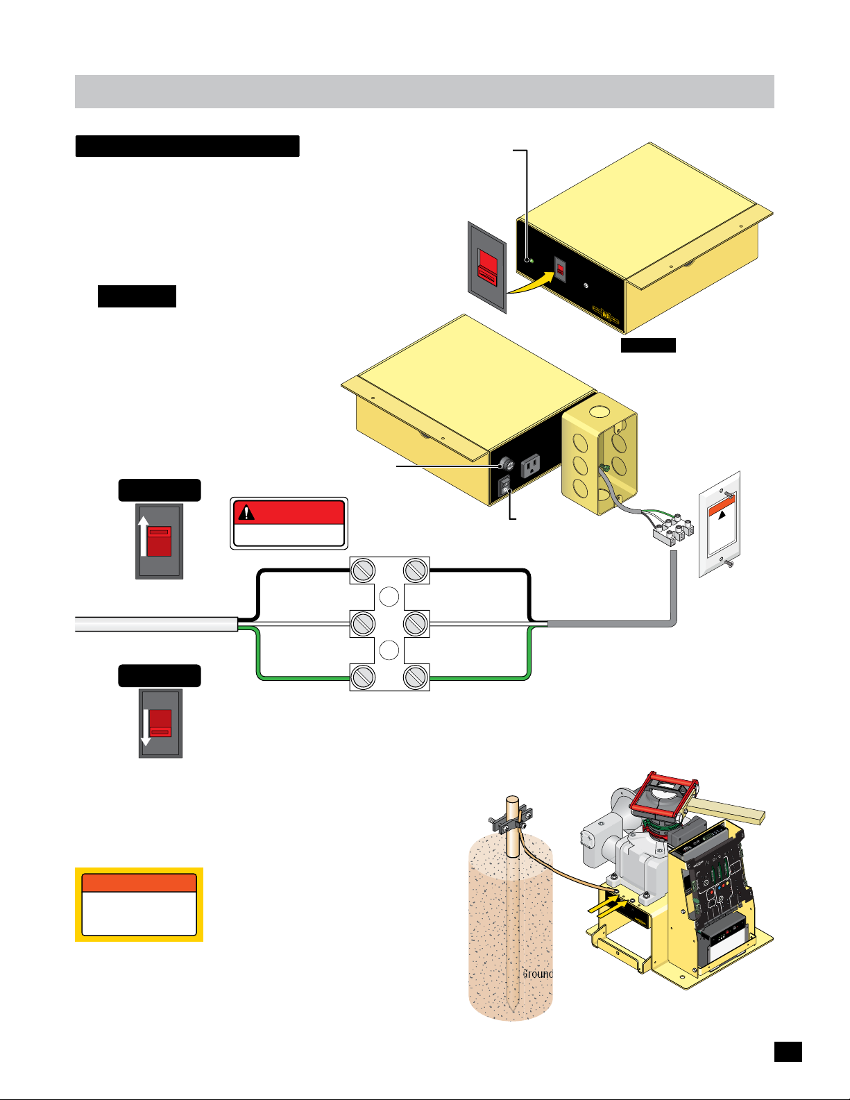
Wiring operator
WARNING
W
ARNI
NG
HI
G
H
V
O
L
T
AG
E
input ac power
AC IN Power LED
Wire input AC power wire to the MAX Megatron Toroid box as shown.
Choose either 115V or 230V setting on input AC power selector switch.
NOTE: AC power wire is required for EACH gate operator
when using dual gate operators.
Input AC Power
Selector Switch
CAUTION: Make sure circuit
breaker is OFF from incoming
AC input wire BEFORE wiring!
MAX
Megatron
Toroid Box
Input AC Power Options
Single Phase 115VAC Only
115VAC
Set to 115V
115V
115 OR 230VAC
Power Wire
DANGER
HIGH VOLTAGE!
Line (Black)
Neutral (White)
7 Amp Fuse
Power Terminal
Line (Black)
Neutral (White)
A
230V
C
IN
5
1
1
Se
Vo
115V
2
MAX
Me
ga
tron
ion
ct
ote
e
pr
h
d
t
h
it
inue
nt
.
ly w
co
se
r
on
u
o
f
F
f
ce
s
o
s
a
a
G:
pl
p
le
e
N
ing
e
I
r
e
t
r
t
n
a
N
r
n
e,
e
l
R
r
i
ur
d
b
A
o
n
si
a
st f
W
p
on co
fu
i
in
e
T:
s
n
ct
N
yp
e
u
e
t
E
u
aga
r
e
q
i
m
lise
i
t
a prot
sa
l
u
érist
ISSEM
e
,
ct
T
e
tr
t
ra
R
di
E
n
me
ca
V
o
ce
r
A
et
p
e
d’in
m
co
es
s typ
u
me
risq
s.
mê
e
l
de
na
i
nom
p
7 Am
E
S
ax
m
FU
A
On
3
ER
C
W
VA
PO
15
1
f
Of
DO NOT TURN POWER
ON AT THIS TIME.
Back of MAX
Megatron
Toroid Box
lect In
l
tage
p
u
t
AC
3
0V
o
r
AC
To
www
ro
id
.
Max.
U
S
.
com
CAUTION: If power selector
switch is set for 115V but
input power is actually 230 V,
7 Amp Fuse will blow.
AC Power
Gang Box
Power
Terminal
WARN
VO
power
ser
HIGH
disconnec
v
T
L
icing unit
ING
!
E
AG
t
ore
f
be
Single Phase 230VAC Only
Set to 230V
Operator MUST be Properly GROUNDED
Any of the Chassis Grounds can be used. They are located next to
the gear reducer. DO NOT remove any existing green ground wires.
to a ground point within 10 feet of the gate operator. The ground
point must be at an electrical panel, a metallic cold water pipe that
runs in the earth, or a grounding rod.
230VAC
230V
WARNING
connect chassis
to ground rod for
lightning protection
NOTE: Consult city codes for AC line wiring.
Beware of existing underground services.
Chassis (Green)
IMPORTANT NOTE: Make sure there are NO exposed
bare wires at the power terminal connection.
Proper grounding of this gate operator is a
requirement for LIGHTNING PROTECTION
in lightning prone areas. To be effective,
ground connections should be made with a
minimum 12 AWG, 600 volt insulated wire
Chassis (Green)
Ground
within 10 ft
of operator.
Chassis
Ground
Grounding Rod
0
0
-2
oller
r
ont
MC
C
R
r
to
p
WE
o
a
tr
O
M
n
P
E
L
U
e
l
l
g
d
Ce
E
X
I
to
o
R
h
T
NE
I
l
P
1
A
L
-
M
el
e
o
g
C
d
2
ON
2
E
hot
P
1
W
dge
t S
i
D
E
dge
m
i
N
L
E
T
G
R
LT
Jog
g
Jo
G
T
H
JO
IG
R
G
T
O
F
J
E
L
y
D
it
v
N
R
AX
ti
i
O
E
M
D
ns
4
e
3
5
LE
S
6
1
r
d
5
1
to
o
4
oa
1
L
3
M
r
2
1
1
ve
O
D
R
E
B
O
AR
M
D
AT
R
IX
RS-485 (+) -
RS-485 (-) -
PWR 24V -
AC
I
5
N
11
S
el
ect
V
Input
ol
tage
1
15
VA
230V
C
or
AC
M
A
X
M
e
ga
t
ro
n
Toro
w
ww.M
id
a
x.
U
S.co
m
GND -
M
O
G
C
A
K
M
C
C
K
N
O
C
L
O
G
L
A
Y
A
c
M
L
Se
E
2
Y
D
R
c
A
Se
5
.
IM
1
R
F
P
TE
F
O
O
A
N
G
r
e
p
N
M
m
E
a
O
P
T
C
T
O
H
IG
D
R
N
Y
N
G
E
ER
P
DE
T
O
N
T
O
I
F
E
r
AT
M
L
e
B
p
TE
m
A
-UP
G
K
Ta
R
C
VE
N
A
A
OLS
E
PE
PE
B
L
E
O
M
SED
M
I
O
TR
T
TA
CL
1
IX 1
ON
R
Y
C
T
A
VE
E
ELL
A
FET
E
M
S
L
N
OC
SA
T
PE
O
O
LO
H
P
1
SA
N/C
U
E
MO
n
i
G
ER
D
T
E
ADE
TO
N
OPE
M
E
C
C
R
2
GE
D
E
T
Power
UL
EXI
UTOMATI
UG
A
In
P
PL
A
TI
R
N
ID
A
NT
I
E
NPU
ATE
G
ERROR
L
I
TS
M
A
O
T
TO
F
F
R
O
PA
V
C
2
N
K
B
1
O
AT
S
M
T
T
WI
E
E
R
RY
T
R
C
LA
H
T
M
A
L
I
T
E
MI
R
L
XI
E
AL
AR
M
CE
P
S
A
T
U
L
RE
A
GND
N
O
I
T
MO
R
E
R
T
N
E
SAF
D
I
G
LU
1
G
N
E
MOTO
P
O
X
A
M
OM
E
C
S
F
O
F
MIN
O
L
SE
C
Y
T
ER
LO
C
M
I
TY
P
T
VI
I
TE
T
E
L
A
TO
SI
S
S
G
IA
N
S
T
LO
SE
R
Y
A
TU
C
AD
N
P
SE
A
O
E
R
N
L
P
TER
E
ST
VE
O
ER
T
P
V
RE
A
O
O
SE
B
R
U
/
O
T
N
I
O
CH
M
NG
T SWIT
PPI
I
I
D
M
SL
X
LI
P
A
O
PEE
WER
N
M
S
AM
CL
PO
N
ATE
O
G
TI
LE
I
R
S
E
B
O
D
P
R
A
N
D
CO
MI
S
E
I
R
N
V
D
T
RT
I
X
G
O
A
M
M
P
I
H
X
L
24
E
C
O
D
T
B
B
E
T
E
O
WI
K
N
I
S
C
A
L
M
A
S
L
B
ON-
G
O
C
LO
N
OR
C
T
E
C
TOP
E
VD
N
2
MO
I
P
S
C
L
E
S
O
E
ON-
T
D
A
N
G
)
D
(
N
L
ARY
)
R
G
L
M
+
E
(
D
C
PRI
E
T
A
VD
G
4
)
R
C
D
2
(
/
N
)
D
G
D
TO
N
+
G
D
(
N
O
A
G
D
H
E
P
N
K
EN
D
I
EYP
G
P
N
K
O
TR
G
PT
D
D
E
S
N
X
N
.
D
A
G
D
G
G
I
E
N
M
O
S
I
R
G
I
D
F
O
I
A
D
R
A
R
7
C
B
odule
y M
MAX
atter
B
IN
ry
te
t
a
B
rror
E
T
ES
T
y
r
ge
a
atte
ce
B
a
l
p
Re
F
ry
ry Volt
e
t
t
F
B
a
tte
B
OF
AT
/
/2
Ba
1
ON
ry
T
e
ER
tt
a
E
B
Y
I
N
19
Page 22
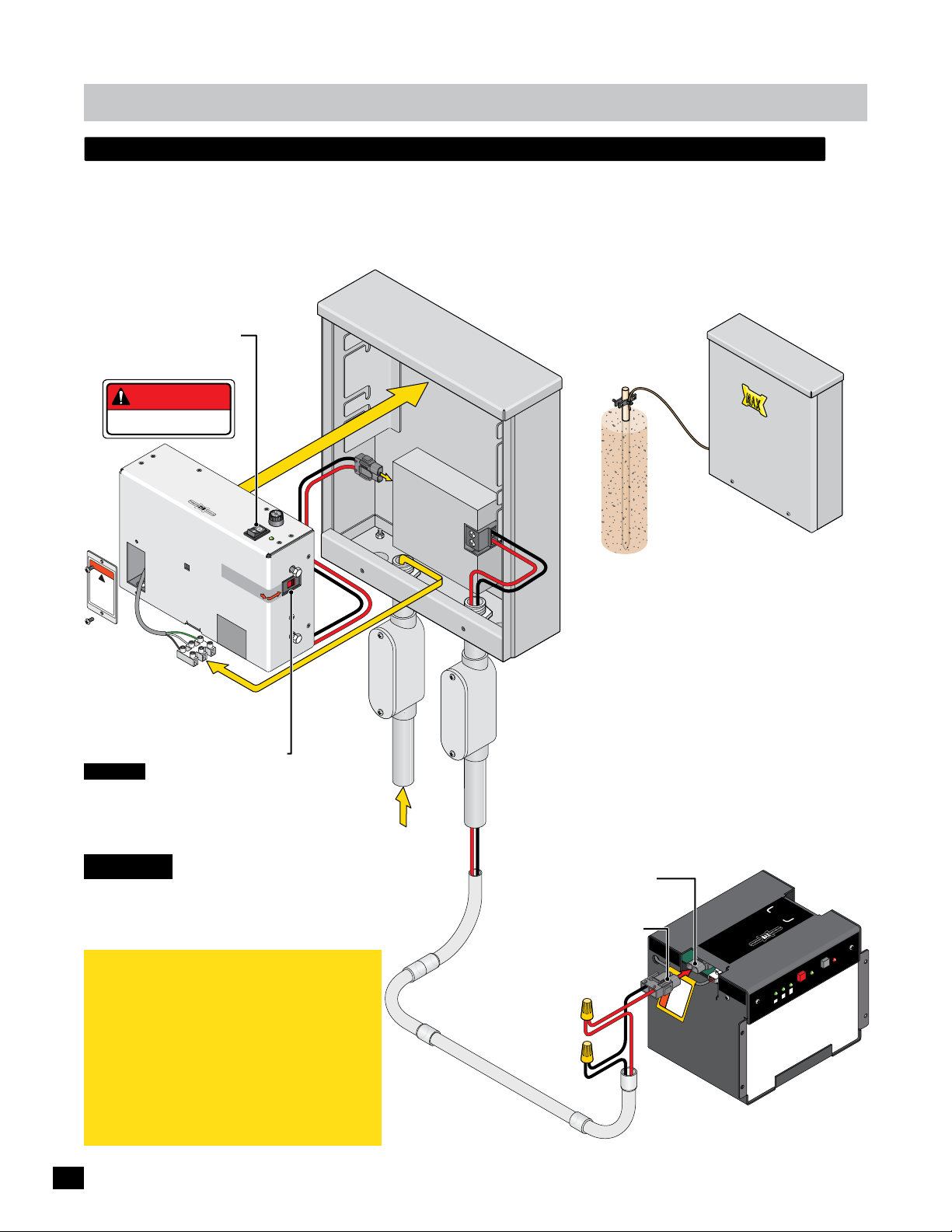
W
AR
N
I
NG
HI
G
H
VO
LT
AG
E
Wiring operator
r
X
g
low voltage remote power supply kit - optional
A MAX Magic Box Kit (sold separately) is required to remotely install a Remote Toroid 15 Amp box at the AC power source.
Plug in Remote Toroid 15 Amp connector to Power In at MAX Magic Box. Wire input AC power to the Toroid 15 Amp box.
Choose either 115V or 230V setting on input AC power selector switch. Run 24V low voltage wires (not included) from the
MAX Magic Box connection to the gate operator and wire to POWER/SOLAR IN connector (Polarity Matters!).
Remove the Remote Toroid 15 Amp connector from the BC-7 battery module POWER/SOLAR IN port. Plug the Magic Box
POWER/SOLAR IN connector into the POWER/SOLAR IN port.
At MAX Magic Box
DO NOT TURN POWER
ON AT THIS TIME.
DANGER
HIGH VOLTAGE!
Y
L
P
P
SU
R
OWE
P
MAX PS-24
Remote Toroid 15 Amp Box
WARNING
!
HI
G
VOLTAG
H
dis
conn
p
E
owe
ect
s
r
e
b
r
vi
ef
c
o
in
re
g
uni
t
Power Terminal
Wires
Line (Black)
n USA
i
e
Mad
REMOV
Sel
ec
115VAC or 230V
warran
VOIDED
i
f
l
a
MP
A
7
USE
F
F
R
F
E
O
OW
N
P
O
IN
AC
t
I
nput
V
230V
ol
ta
ge
:
AC
t
y
bel
i
s
ED
Input AC Powe
Neutral (White)
Chassis (Green)
Input AC Power Selector Switch
CAUTION: If power selector switch is
set for 115V but input power is actually
230 V, 7 Amp Fuse will blow.
NOTE: Consult city codes for AC line wiring.
Remote
Toroid 15 Amp
Connector
Gr
oun
d
r
Input Power
115 VAC or
230 VAC
Input AC Power
Power In
NOTE: A MAX Magic Box kit is required for EACH gate operator
when using dual gate operators.
Ground
within 10 ft
of Box
GND
Grounding Rod
Pos +
24V
Wires
10 AWG
Minim
MAX Magic Box MUST be
um
Properly GROUNDED
IMPORTANT: MAX Magic Box and Gate Operato
MUST EACH be Properly GROUNDED. Proper
grounding is a requirement for LIGHTNING
High Voltage
PROTECTION in lightning prone areas. To be
effective, ground connections should be made
24 VDC
Low Voltage
To Operator
with a minimum 12 AWG, 600 volt insulated
wire to a ground point within 10 feet of the MA
Magic Box and gate operator. The ground point
must be at an electrical panel, a metallic cold
water pipe that runs in the earth, or a groundin
rod.
NOTE: Beware of existing underground services.
CAUTION: MAKE SURE CIRCUIT
BREAKER IS OFF AT POWER
SOURCE BEFORE WIRING
IMPORTANT NOTE: Maximum Control’s remote
power supply technology does NOT utilize the
battery power from the MAX BC-7 Battery
Module during NORMAL gate operation.
Battery power is reserved for back-up power
ONLY when an AC power failure occurs. As a
result, battery life is NOT shortened.
This low voltage system can CONTINUOUSLY
cycle the gate during NORMAL gate operation,
perfect for high traffic gate applications.
20
POWER/SOLAR IN
POWER/SOLAR IN
(Included in kit).
Pos +
Polarity Matters!
24V Low Voltage Wire
in Conduit to Gate Operator
GND
Connector
Port
OW
P
OT
O M
O
m
T
o
R
c
NT
S.
U
CO
.
Max
www.
AR
L
O
P
OWE
R
/SOLAR
IN
TAN
POR
M
I
S
/
R
N
I
WE
O
P
RY
E
T
N
I
BAT
T
”
B
ATTE
IN
e
ct to
nne
TERY
co
AT
efore
B
b
“
I
N
us
ry
e
t
t
a
B
E
R
Y
MAX BC-7
Battery Module
At Gate Operator
R
E
IN
R
y
O
R
er
t
E
L
L
Bat
ack
P
7
le
u
od
AX BC-
M
M
ery
t
t
Ba
y IN
r
atte
r
B
o
r
Er
EST
T
e
g
ttery
a
a
ce
B
a
pl
Volt
e
y
R
F1
r
F
atte
B
/OF
/2
N
y
O
r
tte
Ba
Page 23
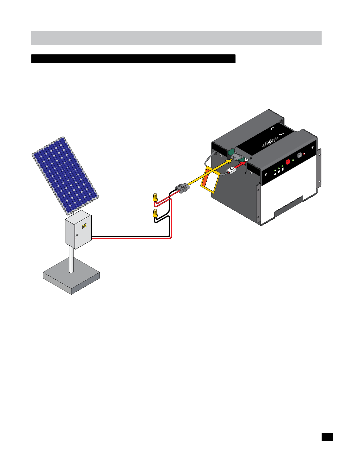
Wiring operator
solar power connection - optional
Refer to Solar application guide.
POWER/SOLAR
IMPORTANT
connect to
before use
“BATTERY IN”
IN
NOTE: Cover solar panel from
sunlight BEFORE wiring plug to
solar panel to prevent a shock
from occurring.
Pos + Red
Polarity Matters!
Connect to
POWER/SOLAR
IN
PO
WER/SOLA
IN
ww
R
ATTERY
B
BATTERY
IN
w.Max.US.com
IN
OWER
P
OT
M
O
TO
R
CONT
Battery Voltage
E
IN
R
O
ry
e
ER
ck
LL
Batt
Pa
MAX BC-7
Battery Module
IN
r
Battery
Erro
TEST
Battery
Replace
F
F
Battery
1/2
ON/OF
ery
Batt
Max Solar
Power Kit
(Sold separately)
GND Black
MAX BC-7 Battery Module
(Approximately 450 cycles using only battery power)
21
Page 24
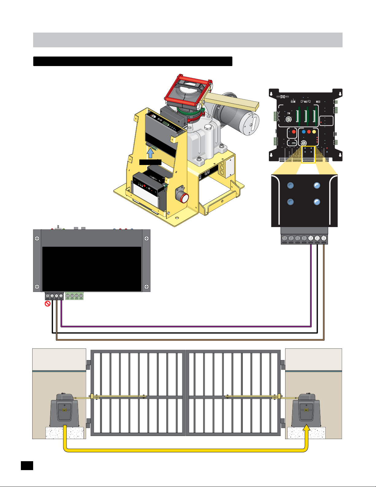
Wiring operator
secondary operator to matrix 1
Unplug 4-Pin plug from the bottom of the
MAX MC-200 motor controller and connect
RS-485 wires as shown below.
Ov
M
o
e
tor
rL
o
a
d
ER
S
E
e
R
n
D
s
i
D
t
i
vi
ty
5
1
2
4
1
3
3
1
4
1
1
5
6
JO
MA
LE
G
L
E
F
X
D
T
O
N
JO
R
G
I
GH
T
LT
T
g
o
R
J
D
g
o
N
1
J
G
e
g
d
ge 2
E
Ed
hoto
ll
P
Ce
M
AT
O
N
R
-
I
L
X
IN
NOTE: The Alarm Shut-Off is
located on the Primary gate
operator ONLY. There is NO
alarm shut-off button on the
secondary gate operator.
Secondary
Gate Operator
(NO Matrix 1)
MAX MC-200
D
IX
BOAR
TR
PWR 24V -
MA
RS-485 (-) -
RS-485 (+) -
GND -
4-Pin Plug
P
O
W
E
R/
S
O
I
N
BAT
TER
I
N
Y
Battery
V
E
oltage
1/
2
F
O
N/OFF
MAX
B
B
a
tte
at
Re
t
ry
e
plac
B
e
a
tte
ry
TE
S
T
B
a
ttery
B
a
ttery
E
PWR 12V -
L
AR
BC-
ry
Modu
7
l
e
IN
r
ro
r
E
Ed
L
i
m
g
1
e
i
t
SW
Mo
U
2
L
E
n
to
MC
t
E
r
a
d
r
p
g
e
C
-
o
Ph
20
P
n
o
tr
t
OW
o
Ce
o
0
l
l
l
le
ER
r
not used -
not used -
GND -
RM
A
AL
H
C
IT
W
S
IT
M
I
L
CK
A
P
Y
R
E
T
AT
S
B
NPUT
I
R
O
T
MO
In
r
Powe
OTOR
M
www
.Max
.U
S
.c
om
CO
T
O
NT
M
P
O
O
ROL
TO
W
E
R
I
L
R
N
E
R
N
I
o MC
T
Batte
Pack
r
OWER
y
P
k
To MC
ry Pac
Batte
n
o
i
t
ec
t
o
r
p
e
h
ed
h t
u
t
i
n
i
y w
cont
nl
r
o
use.
f
Fo
ce
of
a
as
es
l
pl
ng
e
NG:
i
e
r
e p
t
,
n
a
NI
ntr
e
e
r
l
r
i
d r
f
b
ou
n
t
si
n co
p
a
WAR
u
o
f
i
e
s
ains
ct
NT:
yp
un
t
E
ue
ag
r
ote
e
q
r
i
M
se
p
m
i
st
l
i
i
a
SE
l
sa
ut
ér
S
t
I
e
r
T
e,
t
i
ac
t
r
d
e
ER
ca
m
V
o
A
et
ncen
pr
i
’
e
d
m
p
y
s
t
co
s
ue
e
sq
i
r
êm
.
m
es
al
de
n
i
nom
p
Am
7
E
x
S
ma
FU
A
On
R
3
E
W
PO
5VAC
11
f
Of
Primary
Gate Operator
Matrix 1
BATTERY
MATRIX 1
MADE in USA
AUTOMATIC OPEN/CLOSE CONTROLS
EXIT
CENTER
SAFETY
CLOSE TIMER
ID
PLUG
12VDC
GND
24VDC
GND
RADIO SIG.
RADIO GND
PRIMARY
ANTI
TAILGATE
MIN
FIRE DEPT
GATE
(+)
BACK-UP MODE
LEAVE
OPEN
OFFON
MAX
OFF
POSITION
RECORDER
OBD PORT
BLACK BOX
GND
PARTIAL
OPEN
LEAVE
CLOSED
GND
PRIMARY
GATE
OPEN
OPEN
LEFT
1 TIME
MOTOR MOTION
OPEN
MAX
GATE SPEED
MIN
MAX
PRIMARY
GATE
(+)
LIMIT
SWITCH
ON-LINE
MOTOR
ON-LINE
(-)
OPEN
RIGHT
MOTOR
ON-LINE
GND
(-)
SAFETYCENTEREXIT
STOP CLOSE
REVERSE SENSITIVITY
MOTOR OVERLOAD
NO LIMIT SWITCH /
CLAMP SLIPPING
SEC
GATE
(+)
GND
(-)
GATE
(+)
OFF
SEC
MAGLOCK
DELAY
2Sec1.5Sec
GATE
TAMPER
UL
ENTRAP
GATE
STATUS
GND
MAG
LOCK
UL ALARM 12V
(-)
Tamper NO
Tamper IN
PHOTOCELL
ALARM RET
24V
COM
NC
COM
GND
EDGE 1
EDGE 2
ID PLUG
ERROR
RESET
GND
OPEN
COM
CLOSE
BATTERY
IN USE
POWER
GND
4-Pin Plug
NO 24V
Matrix 1
MATRIX
BOARD
RS-485 (+) -
RS-485 (-) -
PWR 24V -
GND -
to
Secondary
Operator
MAX MC-200
PWR 12V -
not used -
not used -
GND -
3 Wires to Matrix 1
ALARM
LIMIT
SWITCH
Connect (3) three RS-485 wires from the
SECONDARY operator’s MAX MC-200 motor
controller to the Matrix 1 - SEC GATE.
• Pos (+) to Pos (+)
INPUTS
PACK
BATTERY
Power In
MOTOR
MOTOR
• Neg (-) to Neg (-)
• Gnd to Gnd
• DO NOT connect PWR 24V.
22 AWG Min. 3-conductor
twisted pair, shielded cable
PrimarySecondary
22
3 Wires to Matrix 1
Page 25
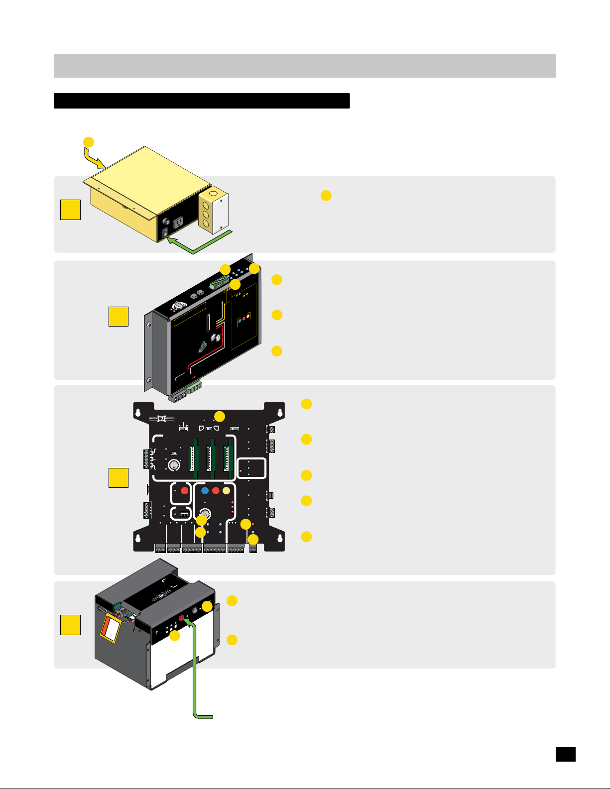
Wiring operator
turn on/off operator power
Operator should have Input AC power wired to Toroid Box, 24V & RS-485 wired between Matrix 1 and MC-200.
TURN POWER ON. Certain LEDs should normally turn ON accordingly:
Located on back of box.
4
A
MAX Megatron Toroid Box
protection
e.
s
For continued
G:
g of fu
N
ne pas
r
ratin
RNI
ble
i
s
WA
: pou
nst fire, replace only with the
fu
NT
es
type and
E
agai
e
qu
ser un
m
EM
protection contre les
li
ti
a
S
sa
S
I
RT
ettre l
E
m
V
ro
1
A
p
incendie, u
d’
m
co
es
es type et caractéristi
qu
ris
êm
.
m
de
nominales
Amp
7
FUSE
On
R
WE
PO
115VAC 3A max
f
Of
Turn AC Power
Switch ON
Battery power automatically turns ON.
0
er
roll
MC-20
R
ap
tr
OWE
Motor Cont
n
P
E
UL
B
l
l
MAX MC-200 Motor Controller
toCe
Pho
e “LEARNED”
b
MUST
:
3
be
T
&
2
US
s
be
M
T
ey can be
th
MUS
ORE
Sensors
D
EF
B
Cell can
ed inputs
unus
y
OP
2 or 3.
and/or Photo
.
rix 1
OPEN & ST
time on Mat
OLD the
earn mode begins
same
e
d, l
hear
OTOR MOTION
M
ted
LOSE
C
indica
OP
ted
5 min.
NST
ON
for
detec
s
each
WILL be
Ds
ON for
dual
LE
5 min.
when
e,
C-200.
thin
od
wi
m
sed.
learn
on again
t
.
but
ED
R
TO
MONI
MOTORPower In
POWER LED:
B
Normal - Turns ON.
Error - Not ON. Check POWER IN plug on bottom of MC-200.
C
Matrix On-Line LED:
Normal - Turns ON.
Error - Not ON. Check RS-485 wiring to Matrix 1.
D
Limit SW On-Line LED:
Normal - Turns ON.
Error - Not ON. Check LIMIT SWITCH plug.
2
C
Edge
X
I
R
T
1
MA
N-LINE
Cell
2
O
2
Edge
Photo
t SW
Edge
mi
Li
Edge 1
T
GND
R
LT
Jog
og
J
T
JOG
GH
RI
JOG
LEFT
ty
X
N
O
ERD
MA
D
4
3
5
LE
Sensitivi
r
Moto
erLoad
Ov
RD
E
4
1
3
2
1
1
AUTION:
C
ATTENTIO
Entrapment Protection
MC-200 Swing
Sensor Guidelines
WILL NOT
ensor MUS
s
or
t
A
•
opera
NORMALLY
ORED sen
T
Wire
•
’s
ONI
or
t
M
.
opera
g Ed
are used
in
Revers
•
PW
be wired to
MONITORED
MC-200
•
power
UNUSED
•
JUMPERED
TRIX 1
MA
RS-485 (-) -
PWR 24V -
GND -
6
1
5
1
struct
n
i
st
n
lation
l
a
st
See in
ir la notice d’i
Vo
N:
EDGE
d to
be wire
(N.C.
function.
T
, to
CLOSED
ONLY
sors
0 when dual operators
oto Cell c
MC-20
Inputs
3
and/or Ph
e
e
g
be used to
of th
.
s
ANY
MUST
n
sensor
mai
R 12V
.
T re
MUS
inputs
0
or fault will occur
MC-2
ONLY power entrapment protection
PWR 12V
sensors with MC-200 PWR 12
RS-485 (+) -
GND
ALARM
-
-
-
-
ns.
io
llation.
a
or
1
)
ach
e
Monitored
an
h
P
Cell
.
3
2
1
GND
MUST be
12V
PWR
0
T
MI
I
L
SWITCH
Monitored
Reversing
Edge
oto
BA
MUST jumper
D
Entrapment Protection
3
Inputs:
2
unused inputs
1
-
-
3
&
-
2
R sensors.
TO
puts
Edge 2
In
Photo Cell
GND
o MONI
t
Edge 1
RE
Jog RT
o LEARN input
TO
T
Jog LT
inputs
MONI
1.
An
wired to
earned.
ered.
p
l
g Edge
jum
to either input
Reversin
ired
H
2.
w
th
be
Press and
ns at
3.
beep is
butto
until
PE
O
ode last
m
OR
eping.
Learn
WILL be
M
by be
LEDs
or on
MC-200s
4.
H
ens
s
BOT
ors are u
P
for
TO
S
operat
Press
5.
stops.
to learn sensors and end
e now
ar
s
beeping
Input
sed
u
V
R
TS
MOTO
INPU
TERY
T
PACK
A
Matrix 1
POWER LED:
MATRIX 1
BACK-UP MODE
LEAVE
MADE in USA
OPEN
AUTOMATIC OPEN/CLOSE CONTROLS
ANTI
TAILGATE
EXIT
OFFON
CENTER
SAFETY
MIN
OFF
3
LAR
SOLAR
N
IMPO
RTANT
connect to
“BATTE
SO
N
I
WER/
PO
”
Y IN
R
re use
fo
e
b
PO
W
E
R/
I
CLOSE TIMER
ID
PLUG
POSITION
RECORDER
12VDC
GND
BLACK BOX
24VDC
GND
FIRE DEPT
GND
RADIO SIG.
RADIO GND
WER
N
PO
I
R
O
T
R
O
M
LLE
O
m
T
NTRO
S.co
U
CO
.
x
Ma
.
ww
w
TERY
IN
BAT
age
t
Vol
y
F1/
er
t
BAT
t
2
Ba
T
ER
E
Y
I
N
J
CLOSED
MAX
PARTIAL
OPEN
OBD PORT
MAX OPEN
GND
t
t
Ba
ON/
Bat
GATE
LEAVE
STRIKE
y
r
e
k
c
Pa
Rep
F
Bat
OF
ery
t
H
MAGLOCK
DELAY
OPEN
OPEN
OPEN
RIGHT
LEFT
1 TIME
MOTOR MOTION
OPEN
STOP CLOSE
REVERSE SENSITIVITY
MAX
GATE SPEED
MOTOR OVERLOAD
MIN
NO LIMIT SWITCH /
MAX
G
LIMIT
SWITCH
ON-LINE
MOTOR
ON-LINE
F
PRIMARY
GATE
PHOTOCELL
GND
GND
KEYPAD / RDR
GND
(+)
GND
(-)
SAFETYCENTEREXIT
CLAMP SLIPPING
SEC
GATE
(+)
GND
MAG
2Sec1.5Sec
OFF
LOCK
COM
NC
Tamper NO
GATE
COM
TAMPER
GND
Tamper IN
PHOTOCELL
UL
EDGE 1
ENTRAP
EDGE 2
ID PLUG
ERROR
UL ALARM 12V
ALARM RET
RESET
GND
OPEN
GATE
COM
STATUS
CLOSE
BATTERY
I
IN USE
POWER
24V
GND
OPEN
STOP
CLOSE
COM
GATE DISABLE
E
(-)
MAX BC-7 Battery Module
7
e
l
BC-
J
odu
M
MAX
Battery
K
N
I
tery
Bat
Error
ST
E
T
tery
e
Bat
lac
ery
t
BATTERY VOLTAGE LEDs:
Normal - 3 LEDs turn ON - Fully charged batteries.
Batteries need charging - LEDs will turn on in sequence until batteries are
fully charged. Batteries are NOT necessary when AC power is available.
K
BATTERY IN ERROR LED:
PRIMARY
BATTERY
Normal - Not ON.
Error - Turns ON. Battery not plugged in to BATTERY IN port.
E
Normal - Turns ON.
Error - Not ON. Check 24V wiring from MC-200 Primary.
F
Motor On-Line PRIMARY LED:
Normal - Turns ON.
Error - Not ON. Check RS-485 wiring to Primary MC-200.
G
Limit SW On-Line PRIMARY LED:
Normal - Turns ON.
H
PRIMARY GATE OPEN RIGHT OPEN LEFT LED:
Normal - Turns ON either LED according to switch setting.
Error - Not ON. Check LIMIT SWITCH plug on bottom of MC-200.
I
BATTERY IN USE LED:
Normal - Not ON.
Error - Flashes on and off. Battery not plugged in to BATTERY IN port on
BC-7 Battery Module.
DO NOT CYCLE GATE OPERATOR
AT THIS TIME
AC IN LED:
Normal - Turns ON.
Error - Not ON. Check AC power.
7 Amp Fuse blown. Replace fuse.
Input AC selector switch MUST be set to CORRECT input AC power.
To turn OFF ALL POWER:
1. Turn OFF AC POWER Switch on MAX Megatron Toroid Box. Battery power remains ON.
2. WAIT for 15 seconds.
3. Press and HOLD (approx. 5 seconds) the RED ON/OFF BATTERY button
until MAX BC-7 LEDs turn ON, then release button. LEDs will turn OFF.
23
Page 26
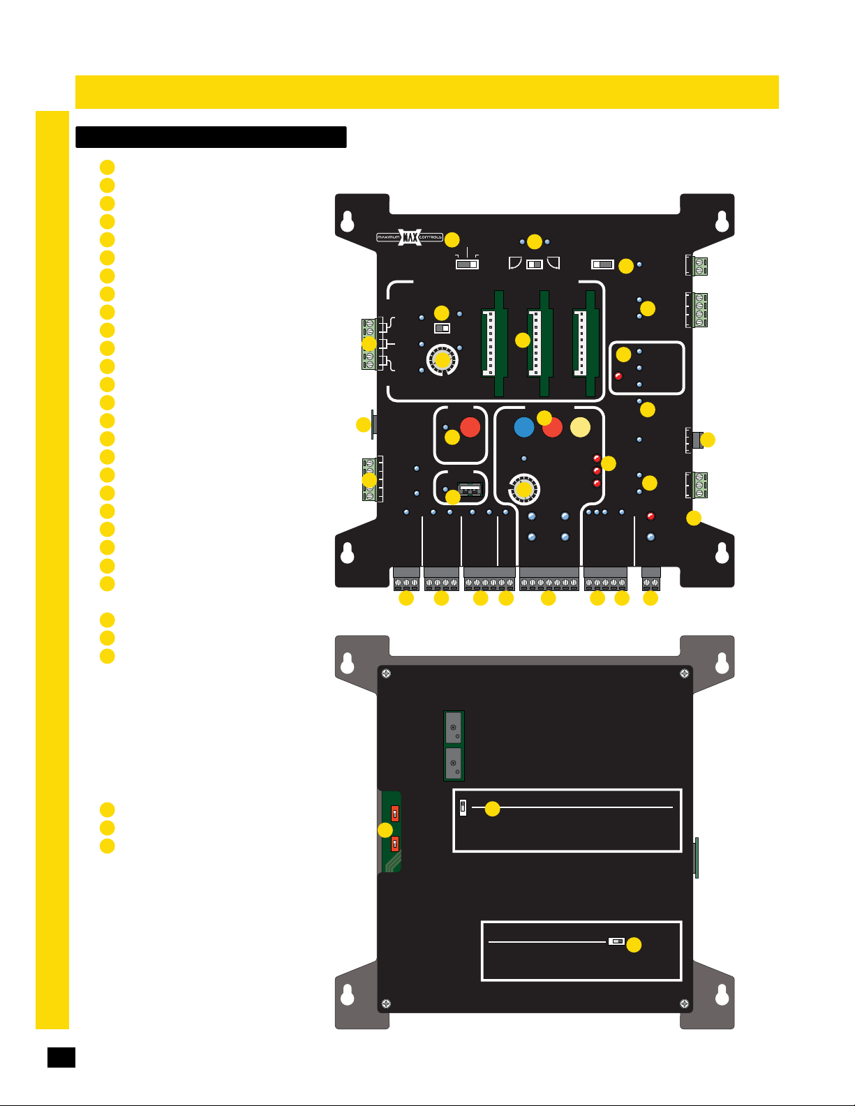
matrix 1 Overview
Battery Back-Up Mode - Page 26
1
Primary Gate - Page 26
2
Maglock - Page 29
3
Gate Tamper - Page 30
4
In-Ground Loop Connection - Page 29
5
Anti Tailgate - Page 27
6
Loop Detectors - Page 29
7
UL Entrapment LEDs - Page 30
8
Close Timer - Page 26
9
ID Plug & ID Plug Error LED - Page 30
10
UL Alarm / Alarm Reset Input - Page 30, 32 & 42
11
Radio Power - Page 28
12
Partial Open - Page 31
13
Stop Button (Alarm Shut-Off) - Page 30, 32 & 42
14
OBD Port Black Box - Page 28
15
16
Selectable Gate Speed Control - Page 26
17
ERD & Motor Overload LEDs - Page 33
18
Gate Status - Page 32
19
Radio Relay - Page 28
20
Emergency Vehicle/Max Open Inputs - Page 30
21
Normal Opening Devices - Page 25
22
Close direction Photocell (N.O.) - Page 25 & 32
Operators Communication LEDs - Page 22 & 33
23
24
OPEN/STOP/CLOSE Connection - Page 32
External Alarm Reset Connection - Page 32
25
Gate Disable - Page 31
26
Matrix 1 Power - Page 33
27
matrix 1
Battery in Use - Page 33
matrix 1
MATRIX 1
MATRIX 1
MADE in USA
EXIT
CENTER
5
SAFETY
ID
10
PLUG
12VDC
GND
12
24VDC
GND
RADIO SIG.
19
BATTERY
BACK-UP MODE
LEAVE
1
CLOSED
LEAVE
OPEN
OPEN
1 TIME
AUTOMATIC OPEN/CLOSE CONTROLS
ANTI
TAILGATE
6
OFFON
9
MIN
MAX
OFF
CLOSE TIMER
PARTIAL
OPEN
13
POSITION
FIRE DEPT
RADIO GND
RECORDER
OBD PORT
BLACK BOX
15
GND
MAX OPEN
GND
STRIKE
GND
MAX
MIN
MAX
KEYPAD / RDR
GND
GATE SPEED
PHOTOCELL
MATRIX 1 Back
PRIMARY
GATE
OPEN
LEFT
7
MOTOR MOTION
OPEN
16
PRIMARY
GATE
GND
(+)
2
OPEN
RIGHT
14
STOP CLOSE
REVERSE SENSITIVITY
MOTOR OVERLOAD
NO LIMIT SWITCH /
LIMIT
SWITCH
ON-LINE
MOTOR
ON-LINE
GND
(-)
2321 2220
SAFETYCENTEREXIT
CLAMP SLIPPING
SEC
GATE
(+)
GND
(-)
MAGLOCK
DELAY
OFF
OPEN
17
STOP
TAMPER
CLOSE
MAG
2Sec1.5Sec
LOCK
3
GATE
8
UL
ENTRAP
GATE
STATUS
COM
GATE DISABLE
2524 26
COM
Tamper NO
COM
4
GND
Tamper IN
PHOTOCELL
EDGE 1
EDGE 2
ID PLUG
ERROR
10
UL ALARM 12V
ALARM RET
RESET
GND
OPEN
18
CLOSE
BATTERY
IN USE
POWER
24V
GND
NC
11
COM
27
24
Gate in Motion Alarms - Page 28
A
Single Pass Anti-Tailgate - Page 27
B
Radio Safety Pause - Page 29
C
ON
Mode 0
OFF
A
ON
Mode 1
OFF
Gate in Motion Alarms
OFF
B
When turned “ON”; After a vehicle clears the Safety Loop, a closing
ON
gate will PAUSE if a second vehicle attempts to tailgate. The second
vehicle must then back off the safety loop for the gate to continue
closing. A new radio signal will open the gate.
ON
Motion Alarm sounds before gate moves and continues until gate stops
Mode 0
OFF
Motion Alarms OFF
Beeper Alert sounds in Battery Back-Up Mode while gate is in motion
ON
Mode 1
Beeper Alert OFF
OFF
Radio Safety Pause
When turned "ON" a moving gate will pause if a radio input signal is
received. The next radio signal causes the gate to continue in the
original direction.
Single Pass Anti-Tailgate
OFF ON
C
MADE IN USAWWW.Max.US.com
Page 27
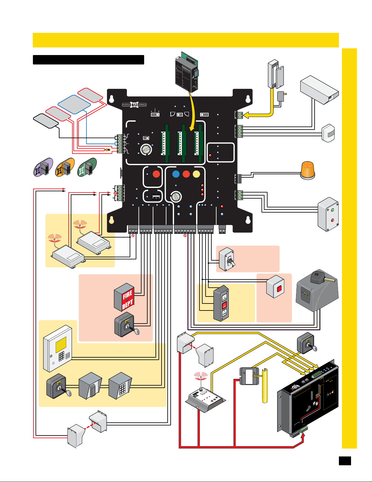
wiring Overview
Safety
In-Ground Loops
See page 29.
Safety
Loop
Exit
Loop
Safety Loops
Wired in series
1400
MAX
MEGATRON
1400 2200FAST
Normal
Opening
Device
4-Wir
Key Switch
12 VDC OR 24 VDC
Photocell
Power
Radi
Loo
p
Center
Loop
N
RO
X
FAST
AT
MA
MEG
N
2200
ATRO
MAX
MEG
ID Plug:
See page 30
PLUG
250 mA Max.
12 VDC
OR 24 VDC
Radio Power
3-Wire
Radio
e
o
See page 28.
Emergency/Security Devices
Emergency OPEN
(Overrides gate
disable switch)
See page 30.
MAX OPEN
(Overrides gate
disable switch)
Normal Opening Devices
Dry Contact (N.O.)
Telephone Entry
Card Reader
Keypad
Photocell (N.O.)
Normally Open Closing Photocell ONLY.
See page 32 (Typically Retro-fit).
NOT UL 325 entrapment protection.
MATRIX 1
ID
12VDC
GND
24VDC
GND
matrix 1
ED
Tel: 480.968.6407
I
ON
DE
F
LECTOMETER
5 =
O
=
ptimum Sens
Inc
1
= Decrea
r
ease Sens.
2
3
SW1
.
4
L
s
ED
e S
ON
S
W
I
P
e
N
ns.
OWER
2
ON
DICA
O
N
Frequen
OFF
O
=
N
O
TO
=
FF
Low
OFF= N
MAX
KEYPAD / RDR
GND
OPEN
LEFT
OPEN
MAX
GATE SPEED
MIN
PHOTOCELL
GND
R
N
S
or
mal Powe
DETEC
o Po
O
N = D
w
T
er
r
O
FF= N
etect
2
Hz
o
D
F
L
la
etec
o
s
op Fault
h
=
t
D
1 Fl
e
l
a
ash
y
T
2
im
F
la
= Open Loop
in
she
g
3 Fl
s=
a
sh
Sho
e
s=
rted Loop
2
Bo
5%
t
h
ch
of In
L
E
a
D’
Cu
ng
d
s
r
e
u
re
Fl
PWR
cta
n
a
t
s
n
h
L
c
L
in
oo
e
E
g
Pr
p
D
=
F
e
F
a
v
lash
ul
ious
t
in
Loop
g=
Fa
u
lt
PRIMARY
GATE
OPEN
RIGHT
MOTOR MOTION
LIMIT
SWITCH
ON-LINE
MOTOR
ON-LINE
PRIMARY
GATE
(+)
GND
ON
O
= Medium
FF
= Medi
SW
O
FF
3
O
= Hi
N
O
= Fail
FF
= Fa
SW4
Se
il
O
Sa
SW5
N
O
O
N
N
O
O
=
O
FF
FF
Pu
O
O
= B sam
FF
N
= Pu
SW
OFF
6
O
= Loop
N
O
= 2
FF
= No D
Secon
SW
7
O
N
elay
O
= N
FF
or
= I
SW
mal
nfini
8
ON
te Presence
O
= Sensitivit
FF
=
N
o Sensi
STOP CLOSE
REVERSE SENSITIVITY
MOTOR OVERLOAD
NO LIMIT SWITCH /
(-)
UL 325
Type B1
Loop Detectors
See page 29.
BATTERY
BACK-UP MODE
LEAVE
CLOSED
LEAVE
MADE in USA
OPEN
OPEN
1 TIME
AUTOMATIC OPEN/CLOSE CONTROLS
ANTI
TAILGATE
EXIT
OFFON
CENTER
SAFETY
MAX
MIN
OFF
CLOSE TIMER
PARTIAL
OPEN
POSITION
RECORDER
OBD PORT
BLACK BOX
STRIKE
GND
FIRE DEPT
GND
MAX OPEN
RADIO GND
GND
RADIO SIG.
(N.O.)
(N.O.)
Dry Contact
(N.O.)
Separate power
for Devices.
O
N
1
2
OPTIONS
3
4
5
6
7
8
0
5
LMA180
6
S
7
8
SEN
c
y
-Low
um-High
gh
c
ure
f
e
ETER
M
ut
p
ut B
LECTO
F
l
s
e on Entr
DE
S
e a
l
y
s
SEN
e on Exit
s
A
Fault
R
E
d
D
elay
POW
T
I
TEC
Pres
E
D
ED
e
nc
e
y
Boost
ti
T
v
i
ty Boos
ESE
R
t
MAGLOCK
DELAY
MAG
2Sec1.5Sec
OFF
SAFETYCENTEREXIT
GATE
TAMPER
LOCK
Tamper NO
Tamper IN
PHOTOCELL
UL
ENTRAP
ID PLUG
UL ALARM 12V
ALARM RET
GATE
CLAMP SLIPPING
GATE
(+)
STATUS
SEC
OPEN
GND
(-)
STOP
CLOSE
COM
GATE DISABLE
24V
GND
24V Power for Matrix 1 from
Primary operator ONLY. See page 33.
Normally Closed Photocell
See page 13 &17.
2
H
ER
W
O
P
1C
H
K
C.
C
.
10
N
/
P
M
O
C
.
C
.
10K
N
/
P
M
O
2
C
T
H
C
C
UT
ELE
TP
S
U
O
1
H
C
S
P
TU
nk
A
R
i
T
S
L
e
ER
W
at
O
G
P
ed
r
N
o
t
AR
20
ni
LE
R
L-
Mo
MG
Wireless
Sensing Edge
Radio Receiver
Refer to wireless
manual for more
information.
Maglock Connection:
Must be specifically
wired,
See page 29.
COM
NC
COM
GND
UL LED Indicators ONLY.
See page 30.
EDGE 1
EDGE 2
ID Plug Error LED. See page 30.
ERROR
RESET
GND
OPEN
COM
CLOSE
BATTERY
IN USE
POWER
Security Device
Gate Disable
N
O
Switch or Timer
F
F
O
See page 31.
Stop
3-Button
Station
See page 32.
Normal
Opening
Device
Security Device
10K Edge
GEM - 104
ON = Obstruction
BLINKING = Fault
MON.
PWR
SAFETY
INPUT
External Alarm
Reset Button
See page 32.
Type B2
GEM-104
Normally
Closed
10K Sensing Edge
wiring, See
page 13 &17.
Power
PRE
to RESET
UL 325
Power
Gate Tamper:
See page 30.
Gate Status:
See page 32.
S
S
y
t
vi
i
RD
t
E
si
n
4
5
Se
d
or
t
a
o
L
Mo
r
2
1
ve
O
D
ER
U
A
C
TE
AT
MC-200 Swing
A se
•
per
o
r
Wi
•
ON
M
per
o
e u
r
a
ever
R
•
e
b
CM
•
ow
p
N
U
•
M
U
J
AT
M
PWR 24V -
Security
Camera
Motion
Sensor
Strobe Light
12VDC
250mA Max
See page 32.
G
GA
Secondary Operator
Connect to MC-200
See pages 22 & 33.
RS-485
External
Open/Close
Key Switch
with Dual
Gates
See page 34.
200
-
C
n
M
Co
r
o
t
ap
tr
Mo
n
P
E
L
U
e
g
d
E
IX
E
ho
TR
N
I
P
1
L
MA
o
N-
t
Cell
dge
2
O
o
E
2
h
e
P
1
g
W
e
d
t S
g
D
E
mi
N
Li
Ed
G
RT
g
LT
Jo
apmen
Jog
MU
ntr
ts:
E
put
u
n
i
p
3
3
3
1
TI
e N
w
U
GND -
14
ON
TI
N
En
so
n
or
t
a
T
I
or’
t
a
sed.
si
e
ir
200
r
e
SED
PER
RI
RS-485 (-) -
1
5
1
O
tr
enso
S
M
r
W
OR
OR
s
ng
d
PW
ON
M
X
JOG
6
Se
:
:
N
apme
UST
ILL
A
M
ED
C
M
Ed
o A
t
R
IT
pu
n
i
o
ED
1
RS-485 (+) -
L
M
LE
ns
i
e
Voi
r Gu
N
LL
se
2
-
ge
Y
N
2V
1
OR
s
t
f
r
PWR 12V
-
G
JO
GHT
I
R
T
EF
X
N
A
O
D
tr
ns
i
on
i
at
inst
l
’
l
d
a
t
ce
i
ot
n
la
r
tection
ro
P
t
n
elines
ED
id
o
t
ed
r
i
on.
i
w
be
N
unct
(
f
t
OT
,
OSED
L
C
l ope
ONLY
Y
ua
s
d
en
nsor
h
w
C
00
o
ot
s.
Ph
r
o
nput
I
nd/
3
a
u
e
h
e
t
b
of
ST
U
M
nsors.
in
se
ED
ema
.
r
r
cu
ST
U
M
t will oc
l
u
a
00
2
-
C
M
powe
LY
s
r
o
ON
ns
se
GND
AL
-
-
-
.
ions
t
uc
ion.
at
l
l
a
or
Moni
ever
GE 1
R
Ed
)
.
C
.
O
ach
s
e
r
o
o
t
a
r
ored
t
Moni
o
n
a
c
l
Phot
el
l
el
C
o
t
d
se
3
2
1
G
N
D
be
ST
MU
V
12
R
PW
ro
p
12
R
PW
entrapment
200
-
r
C
M
h
TT
t
BA
wi
P
IMIT
L
CH
T
I
SW
ARM
MC-200
In
2
nused
u
1
-
-
3
&
-
s
2
s
OR
IT
Edge 2
N
Input
input
Photo Cell
N
GND
R
to MO
A
ED
Edge 1
Jog RT
t
OR
o LE
T
IT
pu
Jog LT
N
n
i
O
o
y
M
n
.
d t
1
A
re
.
i
d
w
e
.
rn
d
a
re
e
l
e
Ed
p
g
m
n
u
j
si
ei
r
o
ve
d t
e
O
R
re
i
.
H
2
w
d
e
e
an
b
h
t
t
ss
a
e
h
s
s
Pr
i
.
ed
3
r
ep
utton
M
to
b
be
l
ti
ng
n
u
si
e
g
PEN
O
e l
R
d
o
.
n m
g
r
n
a
pi
b
e
Le
e
b
LL
y
C
b
WI
M
s
C
ED
r on
L
M
so
4.
H
n
e
T
r
se
O
a
rs
r B
b
o
o
t
f
P
ra
O
T
pe
S
so
o
n
ss
se
e
ps.
rn
Pr
o
.
a
5
st
e
l
g
o
n
t
no
i
p
e
r
e
a
e
b
s
t
pu
d
n
I
e
s
u
n
o
n
i
t
I
c
e
t
wer
V
Po
OR
T
S
MO
NPUT
I
Y
ER
CK
A
Motor
Controller
page 17 &18
matrix 1
ATE OPEN
ED
TE CLOS
r
e
l
ol
r
t
R
WE
O
Cell
o
t
n
tectio
o
er
Pr
p
t
um
j
ST
”
s
D
NE
R
A
E
“L
T be
S
.
MU
:
3
be
nsors
be
e
&
n
ST
2
U
ca
be
s
M
y
rs
ST
the
U
so
E
n
M
R
n
ts
Se
O
u
ca
p
EF
l
n
i
B
el
d
s
C
se
o
t
u
o
n
h
u
.
3
r P
OP
r
o
T
/
o
S
d
1
2
n
&
x
t
a
i
u
r
e
N
s.
p
g
n
n
i
PE
g
Mat
e
O
n
b
o
ther i
e
he
e
t
od
m
i
D
t
m
L
e
rn
m
a
e
sa
l
,
d
N
O
ar
TI
e
O
M
R
O
T
O
E
d
e
t
CLOS
ca
i
d
n
i
.
OP
n
T
i
d
S
e
ct
N
r 5 m
e
t
o
f
e O
s
de
b
st
ch
a
LL
r ea
WI
o
f
l
s
a
N
u
ED
.
O
d
L
n
i
e
.
en
m
0
h
0
5
2
w
,
n
i
e
s
h
d
0
t
i
o
m
-20
.
n w
d
rn
ai
a
e
use
l
ag
d
n
n
o
t
t
u
d e
.
D
an
E
rs
R
O
T
I
MON
w
OTOR
M
25
Page 28
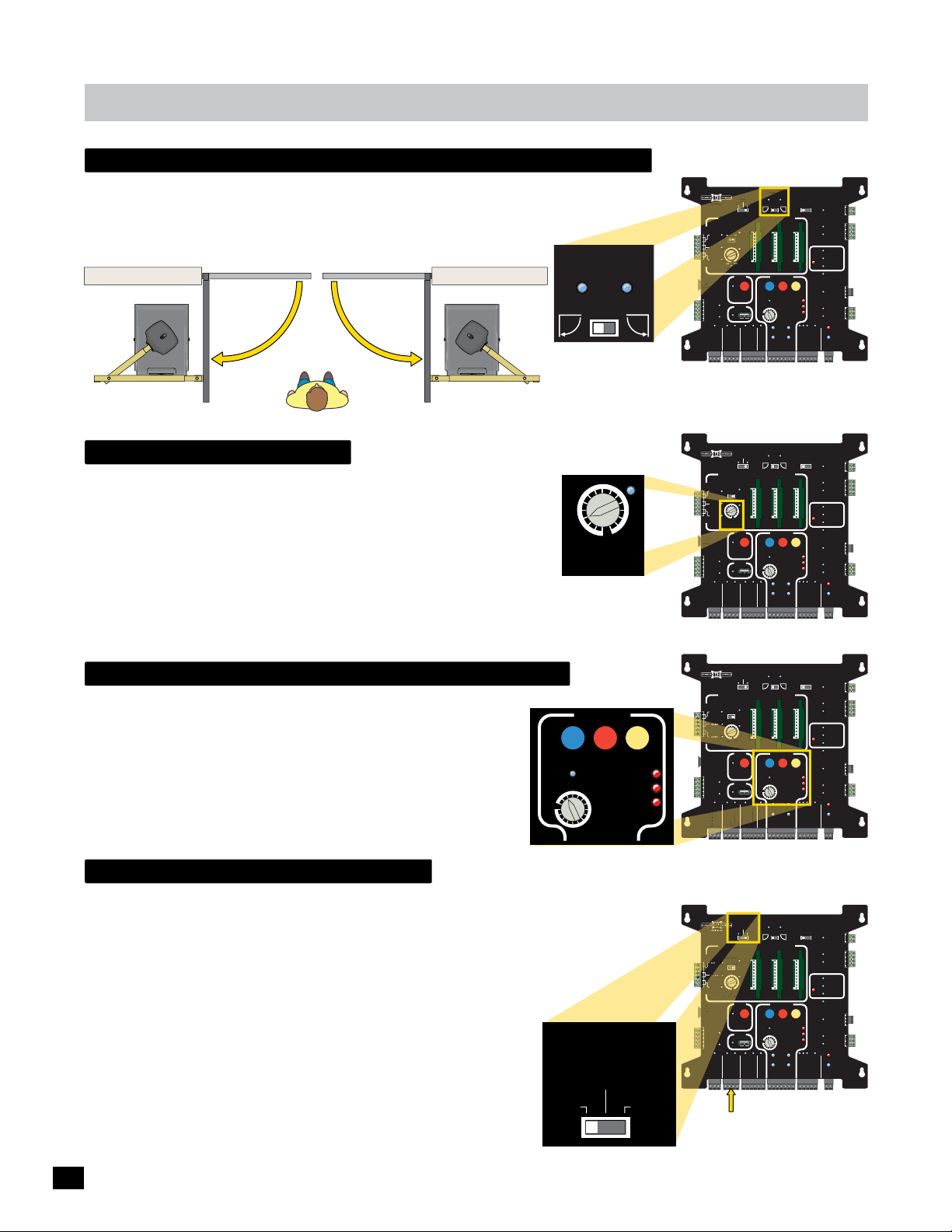
matrix 1
CENTER
EXIT
CLOSE
ID
PLUG
C
R
S
PRIMARY
N
F
D
O
N
O
G
UG
ANTI
UG
N
C
D
C
D
F
N
TIME
primary gate - open left / open right
Set the Primary gate operator with Primary Gate setting. Secondary operator will
automatically be set to the opposite opening direction as the primary gate operator
when using dual gates.
OUTSIDE Property
PRIMARY SECONDARY
INSIDE Property
OPEN RIGHTOPEN LEFT
gate close timer
The Close Timer has 16 selectable settings for automatic gate close time.
Knob at OFF position: close timer OFF.
1st click clockwise - Knob at MIN position: 1/2 sec...
2nd click clockwise: 1 sec...
3rd click: 4 sec...
4th click: 8 sec...
5th click: 12 sec (4 sec increments for each successive click up to 60 sec MAX)
NOTE: 1/2 sec MIN position is recommended for High Traffic areas.
PRIMARY
GATE
OPEN
LEFT
LED turns ON for
MAX setting ONLY
OFF
CLOSE TIMER
OPEN
RIGHT
MAXMIN
BATTERY
MATRIX 1
BACK-UP MODE
LEAVE
LOSED
CLOSED
LEAVE
LEAVE
MADE in USA
OPE
OPEN
AUTOMATIC OPEN/CLOSE CONTROLS
ANTI
TAILGATE
EXIT
CENTER
ENTE
SAFETY
AFETY
CLOSE TIMER
PARTIAL
OPEN
ID
PLUG
POSITION
RECORDER
12VDC
GND
OBD PORT
BLACK BOX
24VDC
GND
FIRE DEPT
GND
MAX OPEN
GND
RADIO SIG.
RADIO GND
BATTERY
MATRIX 1
BACK-UP MODE
LEAVE
CLOSED
LEAVE
MADE in USA
OPEN
AUTOMATIC OPEN/CLOSE CONTROLS
ANTI
TAILGATE
EXIT
OFFON
CENTER
SAFETY
MIN
MAX
OFF
CLOSE TIMER
PARTIAL
OPEN
ID
PLUG
L
POSITION
RECORDER
12VDC
GND
OBD PORT
BLACK BOX
24VDC
GND
FIRE DEPT
GND
MAX OPEN
GND
RADIO SIG.
RADIO GND
PRIMARY
GATE
MAGLOCK
DELAY
OPEN
OPEN
OPEN
LEFT
1 TIME
MOTOR MOTION
OPEN
MAX
GATE SPEED
MIN
MAX
PRIMARY
GATE
PHOTOCELL
GND
STRIKE
GND
KEYPAD / RDR
GND
(+)
PRIMARY
GATE
OPEN
OPEN
LEFT
1 TIME
MOTOR MOTION
OPEN
MAX
GATE SPEED
MIN
MAX
PRIMARY
GATE
PHOTOCELL
GND
STRIKE
GND
KEYPAD / RDR
GND
(+)
RIGHT
STOP CLOSE
REVERSE SENSITIVITY
LIMIT
SWITCH
ON-LINE
MOTOR
ON-LINE
GND
(-)
OPEN
RIGHT
STOP CLOSE
REVERSE SENSITIVITY
LIMIT
SWITCH
ON-LINE
MOTOR
ON-LINE
GND
(-)
SAFETYCENTEREXIT
MOTOR OVERLOAD
NO LIMIT SWITCH /
CLAMP SLIPPING
SEC
GATE
(+)
SAFETYCENTEREXIT
MOTOR OVERLOAD
NO LIMIT SWITCH /
CLAMP SLIPPING
SEC
GATE
(+)
MAG
OFF
2Sec1.5Sec
LOCK
COM
NC
Tamper NO
GATE
COM
TAMPER
GND
Tamper IN
PHOTOCELL
UL
EDGE 1
ENTRAP
EDGE 2
ID PLUG
ERROR
UL ALARM 12V
ALARM RET
RESET
GND
OPEN
GATE
COM
STATUS
CLOSE
BATTERY
IN USE
POWER
24V
GND
OPEN
STOP
CLOSE
COM
GATE DISABLE
GND
(-)
MAGLOCK
DELAY
MAG
OFF
2Sec1.5Sec
LOCK
COM
NC
Tamper NO
GATE
COM
TAMPER
GND
Tamper IN
PHOTOCELL
UL
EDGE 1
ENTRAP
EDGE 2
ID PLUG
ERROR
UL ALARM 12V
ALARM RET
RESET
GND
OPEN
GATE
COM
STATUS
CLOSE
BATTERY
IN USE
POWER
24V
GND
OPEN
STOP
CLOSE
COM
GATE DISABLE
GND
(-)
selectable gate speed control
The Gate Speed knob has 16 selectable settings to choose from.
MAX Megatron 1400/2200 speed varies approx. 11.5 sec to 20 sec.
MOTOR MOTION
MAX Megatron FAST speed of dual gates varies approx. 6 sec to 14 sec.
OPEN
The speed will vary depending on the weight and length of the specific
gate(s). Make sure gate speed is appropriate for the size and length of
the gate(s).
NOTE: The Auto Gate Sync feature provides synchronous opening and
MAX
GATE SPEED
MIN
MAX
STOP CLOSE
REVERSE SENSITIVITY
MOTOR OVERLOAD
NO LIMIT SWITCH /
CLAMP SLIPPING
closing between bi-parting gates (dual gate operators).
LED turns ON for
battery back-up mode
MAX setting ONLY
The Battery Back-Up Mode setting will determine how the gate operator will function during
an AC power failure. Gate operator with a full battery charge should cycle a 2000 lbs gate
(battery power ONLY) approximately 450 times.
LEAVE OPEN - The gate operator will continue to cycle the gate normally until the
battery power can no longer cycle the gate. When this happens, the gate will open
to OPEN position until power is restored, then gate will automatically close.
LEAVE CLOSED - The gate operator will continue to cycle the gate normally until
the battery power can no longer cycle the gate. When this happens, the gate will
close if not already in the CLOSE position, where it will remain until power is
restored. Enough battery power is retained for a LIMITED time to operate
emergency vehicle entry (Using opening devices connected to FIRE DEPT and/or
MAX OPEN inputs to FULLY open gate).
OPEN 1 TIME - The gate operator automatically OPENS gate and REMAINS in the
OPEN position. A open/close command or loop event is needed to close gate.
BATTERY
BACK-UP MODE
LEAVE
CLOSED
LEAVE
OPEN
OPEN
1 TIME
MATRIX 1
MADE in USA
AUTOMATIC OPEN/CLOSE CONTROLS
TAILGATE
EXIT
CLOSE TIMER
ID
PLUG
12VDC
GND
24VDC
GND
ND
ADI
RADIO SIG.
RADIO GND
MATRIX 1
AUTOMATIC OPEN/CLOSE CONTROLS
TAILGATE
SAFETY
AFETY
CLOSE TIMER
ID
D
PLUG
L
12VDC
12VD
GND
N
24VDC
24VD
GND
N
RADIO SIG.
RADIO GND
ANTI
MIN
IN
IRE DEPT
FIRE DEPT
ANTI
MIN
IN
FIRE DEPT
OFF
OFF
BACK-UP MODE
LEAVE
OPEN
OFFON
MAX
AX
F
PARTIAL
OPEN
POSITION
RECORDER
OBD PORT
BLACK BOX
PE
N
GND
MAX OPEN
MAX
BATTERY
BACK-UP MODE
LEAVE
OPEN
OFFON
OFFO
MAX
AX
F
PARTIAL
OPEN
POSITION
RECORDER
OBD PORT
BLACK BOX
GND
MAX OPEN
GATE
LEAVE
CLOSED
OPEN
1 TIME
STRIKE
GND
KEYPAD / RDR
GND
LEAVE
CLOSED
OPE
OPEN
1 TIME
STRIKE
GND
KEYPAD / RDR
GND
MAGLOCK
DELAY
OPEN
OPEN
LEFT
MOTOR MOTION
OPEN
MAX
GATE SPEED
MIN
MAX
PRIMARY
GATE
PHOTOCELL
GND
GND
(+)
PRIMARY
GATE
OPEN
LEFT
MOTOR MOTION
OPEN
MAX
GATE SPEED
MIN
MAX
PRIMARY
GATE
PHOTOCELL
GND
GND
(+)
RIGHT
STOP CLOSE
REVERSE SENSITIVITY
LIMIT
SWITCH
N-LINE
ON-LINE
MOTOR
ON-LINE
GND
(-)
OPEN
RIGHT
STOP CLOSE
REVERSE SENSITIVITY
LIMIT
SWITCH
ON-LINE
MOTOR
ON-LINE
GND
(-)
SAFETYCENTEREXIT
MOTOR OVERLOAD
NO LIMIT SWITCH /
CLAMP SLIPPING
SEC
GATE
(+)
SAFETYCENTEREXIT
MOTOR OVERLOAD
NO LIMIT SWITCH /
CLAMP SLIPPING
SEC
GATE
(+)
MAG
2Sec1.5Sec
OFF
LOCK
COM
NC
Tamper NO
GATE
COM
TAMPER
GND
Tamper IN
PHOTOCELL
UL
EDGE 1
ENTRAP
EDGE 2
ID PLUG
ERROR
UL ALARM 12V
ALARM RET
RESET
GND
OPEN
GATE
COM
STATUS
CLOSE
BATTERY
IN USE
POWER
24V
GND
OPEN
STOP
CLOSE
COM
GATE DISABLE
GND
(-)
MAGLOCK
DELAY
MAG
OFF
2Sec1.5Sec
LOCK
COM
NC
Tamper NO
GATE
COM
TAMPER
GND
Tamper IN
PHOTOCELL
UL
EDGE 1
ENTRAP
EDGE 2
ID PLUG
ERROR
UL ALARM 12V
ALARM RET
RESET
GND
OPEN
GATE
COM
STATUS
CLOSE
BATTERY
IN USE
POWER
24V
GND
OPEN
STOP
CLOSE
COM
GATE DISABLE
GND
(-)
PRIMARY
BATTERY
FIRE DEPT/MAX OPEN Inputs
26
Page 29
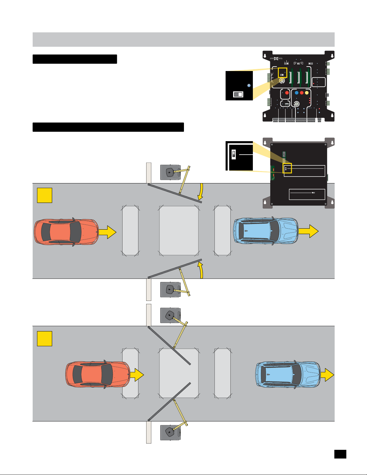
matrix 1
Y
- Gate Pauses -
anti tailgate
Turned OFF - Close timer will close the gate. If an in-ground safety or exit loop
gets activated during the close cycle, gate will REVERSE to the open position.
Turned ON - (In-ground loops required) Gate will close after all the in-ground
loops have been cleared no matter how long the close timer is set for. If an
in-ground safety loop gets activated during the close cycle, gate will REVERSE
to the open position.
Single pass anti-tailgate
Turned ON - (In-ground loops required) Gate will close after all the in-ground
loops have been cleared no matter how long the close timer is set for. When an
in-ground safety loop gets activated during the close cycle, gate will PAUSE and
NOT reopen. When loop is cleared, gate will continue to close preventing
UNAUTHORIZED entry.
1
ANTI
TAILGATE
OFFON
LED stays ON
when Anti Tailgate
is ON
OFF
ON
BATTERY
MATRIX 1
BACK-UP MODE
LEAVE
CLOSED
LEAVE
MADE in USA
OPEN
AUTOMATIC OPEN/CLOSE CONTROLS
ANTI
TAILGATE
EXIT
OFFON
CENTER
SAFETY
SAFET
MIN
MAX
OFF
CLOSE TIMER
PARTIAL
OPEN
ID
PLUG
POSITION
RECORDER
12VDC
GND
OBD PORT
BLACK BOX
24VDC
GND
STRIKE
FIRE DEPT
GND
MAX OPEN
GND
RADIO SIG.
RADIO GND
MATRIX 1 Back
OFF
ON
Mode 0
ON
OFF
ON
Mode 1
OFF
Gate in Motion Alarms
ON
Motion Alarm sounds before gate moves and continues until gate stops
Mode 0
OFF
Motion Alarms OFF
ON
Beeper Alert sounds in Battery Back-Up Mode while gate is in motion
Mode 1
OFF
Beeper Alert OFF
PRIMARY
GATE
MAGLOCK
DELAY
OPEN
OPEN
OPEN
RIGHT
LEFT
1 TIME
GND
OFF
2Sec1.5Sec
SAFETYCENTEREXIT
TAMPER
MOTOR MOTION
OPEN
STOP CLOSE
REVERSE SENSITIVITY
MAX
GATE SPEED
MOTOR OVERLOAD
MIN
NO LIMIT SWITCH /
STATUS
CLAMP SLIPPING
MAX
LIMIT
SWITCH
ON-LINE
MOTOR
ON-LINE
PRIMARY
SEC
GATE
GATE
PHOTOCELL
GND
KEYPAD / RDR
GND
OPEN
STOP
CLOSE
(+)
GND
(-)
(+)
GND
(-)
Single Pass Anti-Tailgate
When turned “ON”; After a vehicle clears the Safety Loop, a closing
gate will PAUSE if a second vehicle attempts to tailgate. The second
vehicle must then back off the safety loop for the gate to continue
closing. A new radio signal will open the gate.
Radio Safety Pause
When turned "ON" a moving gate will pause if a radio input signal is
received. The next radio signal causes the gate to continue in the
original direction.
OFF ON
MAG
LOCK
COM
NC
Tamper NO
GATE
COM
GND
Tamper IN
PHOTOCELL
UL
EDGE 1
ENTRAP
EDGE 2
ID PLUG
ERROR
UL ALARM 12V
ALARM RET
RESET
GND
OPEN
GATE
COM
CLOSE
BATTERY
IN USE
POWER
24V
GND
COM
GATE DISABLE
MADE IN USAWWW.Max.US.com
UNAUTHORIZED Vehicle Approaches
NO VALID open command is given.
Vehicle is attempting to activate safety loop
before the gate’s close cycle is complete,
expecting gate to reopen.
Property
2
SAFETY LOOP
OUTSIDE
SAFETY LOOP
CENTER LOOP
Property
INSIDE
CENTER LOOP
- Gate Pauses -
SAFETY LOOP
AUTHORIZED Vehicle
VALID open command was given.
When last Safety Loop is cleared, gate will close.
NOTE: If a VALID open command is received at this
point, gate will stop and reopen.
SAFETY LOOP
UNAUTHORIZED Vehicle
NO VALID open command.
Safety Loop gets activated and PAUSES the closing gate.
Gate will NOT reopen. Vehicle MUST back up for loop to
clear, then gate continues to close. NO unauthorized entry.
27
Page 30
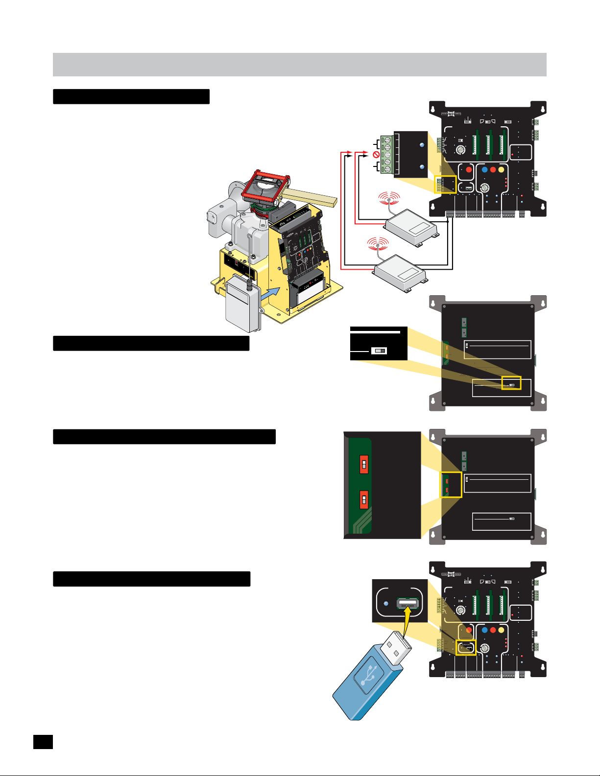
matrix 1
Motion Alarms
1
UG
D
R
CND
C
radio receiver
Connect a 3-wire or 4-wire radio receiver to Matrix 1.
Choose 12V or 24V, 250 ma max. power.
CLOSE TIMER ON - Each time the remote button is pressed
during the Close Timer countdown (gate is open) causes the
timer to reset and begin again. When close timer countdown
is complete, gate will close.
CLOSE TIMER OFF - Sequence when
pressing remote button:
Press One Time - gate OPENS . . .
Press Again - gate STOPS . . .
Press Again - gate CLOSES . . .
Press Again - gate STOPS . . .
Sequence repeats when button is
pressed again.
AC
I
5
N
11
S
el
ect
V
I
oltage
nput
11
5
VA
230V
C
or
A
C
M
A
X
M
e
ga
t
r
o
n
Tor
w
w
oid
w
.M
ax
.U
S.com
ty
i
v
i
RD
it
E
s
4
en
3
5
S
r
d
to
o
oa
L
3
M
r
2
1
1
ve
O
D
R
E
A
RD
AT
RIX
RS-485 (-) -
PWR 24V -
GND -
BATTERY
MATRIX 1
Removable
Choose 12 VDC
OR 24 VDC
(250 mA Max.)
0
0
2
-
oller
r
t
n
o
MC
C
R
r
to
p
WE
o
a
tr
M
n
PO
E
L
U
e
l
l
g
e
d
C
E
X
o
I
t
o
E
R
h
T
N
I
l
P
1
A
L
-
M
el
e
o
g
t
C
d
2
ON
2
E
ho
P
1
ge
W
d
t S
i
D
E
dge
m
i
N
L
E
T
G
R
T
L
Jog
g
o
J
G
T
JO
RIGH
G
T
O
F
J
E
L
N
AX
O
M
D
E
L
6
1
5
1
4
1
MA
BO
M
RS-485 (+) -
M
O
G
C
A
M
C
CK
K
N
O
C
L
G
LO
A
Y
A
c
M
L
Se
E
2
Y
D
R
c
A
Se
5
.
IM
1
R
F
P
TE
F
O
A
NO
G
r
e
p
N
M
m
E
O
P
Ta
C
T
O
H
G
I
D
R
N
GN
RY
E
P
DE
TE
O
N
O
I
T
FT
E
r
A
M
L
e
B
P
p
m
ATE
-U
a
G
T
LS
R
CK
VE
N
A
A
O
E
PE
D
PE
B
L
E
O
SE
M
O
AM
TR
1
TI
T
CL
1
N
IX
O
R
Y
C
T
AD
M
L
VE
E
EL
A
FET
E
A
L
N
OC
S
T
PE
O
HO
P
A
1
S
U
E
MO
n
i
G
E
ER
D
T
E
TO
N
OPEN/CLOS
CE
C
R
2
TI
GE
MA
ED
T
P
UL
XI
o
TO
E
wer In
UG
AU
P
PL
TI
A
R
R
N
E
ID
A
NT
I
E
RO
NPU
AT
G
ER
L
TS
M
AI
O
T
TO
F
F
R
O
PA
V
CK
2
N
B
1
O
ATT
S
M
T
WI
E
E
R
RY
T
A
R
C
H
T
M
AL
LI
T
E
MI
R
L
XI
A
T
E
U
ES
R
AL
D
GN
A
L
N
AR
O
I
M
T
MO
R
E
T
N
TOR
CE
ET
SAF
D
I
G
LU
P
2
1
G
N
E
MO
P
O
X
MA
OM
E
C
S
F
O
F
MIN
O
L
SE
C
Y
ER
LO
C
Y
M
T
P
TI
VI
I
TE
T
E
L
A
TO
SI
S
A
S
G
I
N
S
T
E
LO
S
R
Y
TU
A
C
E
AD
N
S
P
E
N
P
E
STA
VER
O
E
P
E
R
ATTER
O
OVERLO
S
B
R
U
/
O
T
N
I
O
CH
T
M
G
N
SWI
T
PPI
I
I
D
L
M
I
S
X
EE
P
A
O L
WER
N
M
SP
AM
CL
PO
N
ATE
O
G
I
LE
IT
S
ER
B
O
P
RD
A
IN
D
CO
M
S
E
I
R
N
V
D
T
RT
I
X
G
O
M
MA
P
I
H
X
L
24
C
O
D
T
B
B
I
E
TE
E
O
W
K
N
I
S
C
A
L
M
A
S
L
B
ON-
G
O
C
LO
N
OR
C
T
E
C
TOP
E
O
VD
N
M
I
P
S
C
L
E
S
O
E
ON-
T
D
A
N
G
)
D
(
N
ARY
R
G
LL
M
I
E
(+)
D
C
PR
E
T
A
VD
G
)
R
C
D
24
(
/
N
)
D
G
D
TO
N
+
G
D
(
N
O
A
G
D
H
E
P
N
K
EN
D
I
EYP
G
P
N
K
O
TR
G
PT
D
D
E
S
N
X
N
.
D
A
G
D
G
G
I
E
N
M
O
S
I
R
G
D
FI
O
I
A
D
R
A
R
7
C-
le
odu
AX B
y M
r
M
atte
B
N
I
ry
e
tt
Ba
rror
E
EST
T
ry
ge
tte
a
t
ce
Ba
a
ol
l
p
V
Re
F
ry
ry
e
t
t
F
BA
tte
Ba
OF
/
/2
Ba
1
T
ON
ry
T
e
t
E
R
E
Bat
Y
I
N
Terminal
12VDC
GND
24VDC
GND
3-Wire
4-Wire
Radio
dio
a
R
MADE in USA
AUTOMATIC OPEN/CLOSE CONTROLS
EXIT
CENTER
SAFETY
CLOSE TIMER
ID
L
PLUG
12VDC
GND
24VDC
GND
N
RADIO SIG.
RADIO GND
PRIMARY
BACK-UP MODE
GATE
LEAVE
CLOSED
OPEN
OPEN
LEAVE
OPEN
RIGHT
LEFT
OPEN
1 TIME
ANTI
TAILGATE
OFFON
MAX
MIN
OFF
PARTIAL
MOTOR MOTION
OPEN
OPEN
STOP CLOSE
POSITION
RECORDER
REVERSE SENSITIVITY
MAX
GATE SPEED
OBD PORT
BLACK BOX
MIN
MAX
LIMIT
SWITCH
ON-LINE
MOTOR
ON-LINE
PRIMARY
GATE
PHOTOCELL
GND
STRIKE
GND
KEYPAD / RDR
GND
FIRE DEPT
GND
MAX OPEN
GND
(+)
GND
(-)
Receiver Input
SAFETYCENTEREXIT
MOTOR OVERLOAD
NO LIMIT SWITCH /
CLAMP SLIPPING
SEC
GATE
(+)
MAGLOCK
DELAY
MAG
OFF
2Sec1.5Sec
LOCK
COM
NC
Tamper NO
GATE
COM
TAMPER
GND
Tamper IN
PHOTOCELL
UL
EDGE 1
ENTRAP
EDGE 2
ID PLUG
ERROR
UL ALARM 12V
ALARM RET
RESET
GND
OPEN
GATE
COM
STATUS
CLOSE
BATTERY
IN USE
POWER
24V
GND
OPEN
STOP
CLOSE
COM
GATE DISABLE
GND
(-)
Existing holes are for Multi-Code radio receiver
Radio Receiver Mounting Position
or mount using velcro adhesive tape.
Radio safety pause
Turned ON - The radio transmitter (remote control) can PAUSE a MOVING
gate by pressing the remote button. Pressing the remote button again will
cause the gate to CONTINUE in the SAME direction. This process can be
repeated as many times as desired.
gate in motion alarms
MODE 0 - Turned ON - Alarm will sound BEFORE and DURING gate cycle
to alert surrounding area.
NOTE: A strobe light can be connected to UL ALARM connection that will
flash ON and OFF when the alarm is sounding. See page 32.
MODE 1 - Turned ON - Alarm will beep when using ONLY battery power
DURING gate cycling. This brings to attention that only battery power is
being used and NOT normal AC power.
obd port black box
On Board Diagnostics (OBD) port will download a simple .txt file to troubleshoot gate operator errors and to view normal transaction logs.
Plug a USB flash drive into port. LED will flash while file is downloading.
When LED stops flashing, remove flash drive and plug it into any computer
with an available USB port and simple text reader software (typical).
The operator’s event history is stored as a simple .txt file. Contained in
the file is a log of the most recent 1000 events. Quickly identify and
diagnose a complex or intermittent problem. The file can even be
e-mailed to the factory for on site diagnosis if necessary. The files will
be stored as an ongoing event history of the transactions that occur at
the gate operator.
OFF
ON
ON
Mode 0
OFF
ON
Mode 1
OFF
OBD PORT
BLACK BOX
USB Flash Drive
MATRIX 1 Back
OFF
ON
Mode 0
ON
OFF
FF
ON
Mode 1
Mode
OFF
Gate in Motion Alarms
ON
Motion Alarm sounds before gate moves and continues until gate stops
Mode 0
OFF
Motion Alarms OFF
ON
Beeper Alert sounds in Battery Back-Up Mode while gate is in motion
Mode 1
FF
OFF
Beeper Alert OFF
Single Pass Anti-Tailgate
When turned “ON”; After a vehicle clears the Safety Loop, a closing
gate will PAUSE if a second vehicle attempts to tailgate. The second
vehicle must then back off the safety loop for the gate to continue
closing. A new radio signal will open the gate.
Radio Safety Pause
When turned "ON" a moving gate will pause if a radio input signal is
received. The next radio signal causes the gate to continue in the
original direction.
OFF ON
MADE IN USAWWW.Max.US.com
MATRIX 1 Back
ON
Mode 0
OFF
ON
Mode 1
OFF
Gate in Motion Alarms
Mode 0
Mode 1
BATTERY
MATRIX 1
BACK-UP MODE
LEAVE
MADE in USA
OPEN
AUTOMATIC OPEN/CLOSE CONTROLS
ANTI
TAILGATE
EXIT
OFFON
CENTER
SAFETY
AFETY
MIN
MAX
OFF
CLOSE TIMER
PARTIAL
OPEN
ID
PLUG
POSITION
RECORDER
ECORDE
12VDC
12VD
GND
OBD PORT
24VDC
24VD
GND
FIRE DEPT
GND
MAX OPEN
RADIO SIG.
RADIO GND
OFF
ON
ON
Motion Alarm sounds before gate moves and continues until gate stops
OFF
Motion Alarms OFF
Beeper Alert sounds in Battery Back-Up Mode while gate is in motion
ON
Beeper Alert OFF
OFF
LEAVE
CLOSED
ITION
STRIKE
GND
Single Pass Anti-Tailgate
When turned “ON”; After a vehicle clears the Safety Loop, a closing
gate will PAUSE if a second vehicle attempts to tailgate. The second
vehicle must then back off the safety loop for the gate to continue
closing. A new radio signal will open the gate.
Radio Safety Pause
When turned "ON" a moving gate will pause if a radio input signal is
received. The next radio signal causes the gate to continue in the
original direction.
OFF ON
MADE IN USAWWW.Max.US.com
PRIMARY
GATE
MAGLOCK
DELAY
OPEN
OPEN
OPEN
RIGHT
LEFT
1 TIME
GND
OFF
2Sec1.5Sec
SAFETYCENTEREXIT
TAMPER
UL
ENTRAP
MOTOR MOTION
OPEN
STOP CLOSE
REVERSE SENSITIVITY
MAX
GATE SPEED
MOTOR OVERLOAD
MIN
NO LIMIT SWITCH /
STATUS
CLAMP SLIPPING
MAX
LIMIT
SWITCH
ON-LINE
MOTOR
ON-LINE
PRIMARY
SEC
GATE
GATE
PHOTOCELL
GND
KEYPAD / RDR
GND
OPEN
STOP
CLOSE
(+)
GND
(-)
(+)
GND
(-)
NOTE: See page 46 for
more information about
this unique feature.
MAG
LOCK
COM
NC
Tamper NO
GATE
COM
GND
Tamper IN
PHOTOCELL
EDGE 1
EDGE 2
ID PLUG
ERROR
UL ALARM 12V
ALARM RET
RESET
GND
OPEN
GATE
COM
CLOSE
BATTERY
IN USE
POWER
24V
GND
COM
GATE DISABLE
28
Page 31
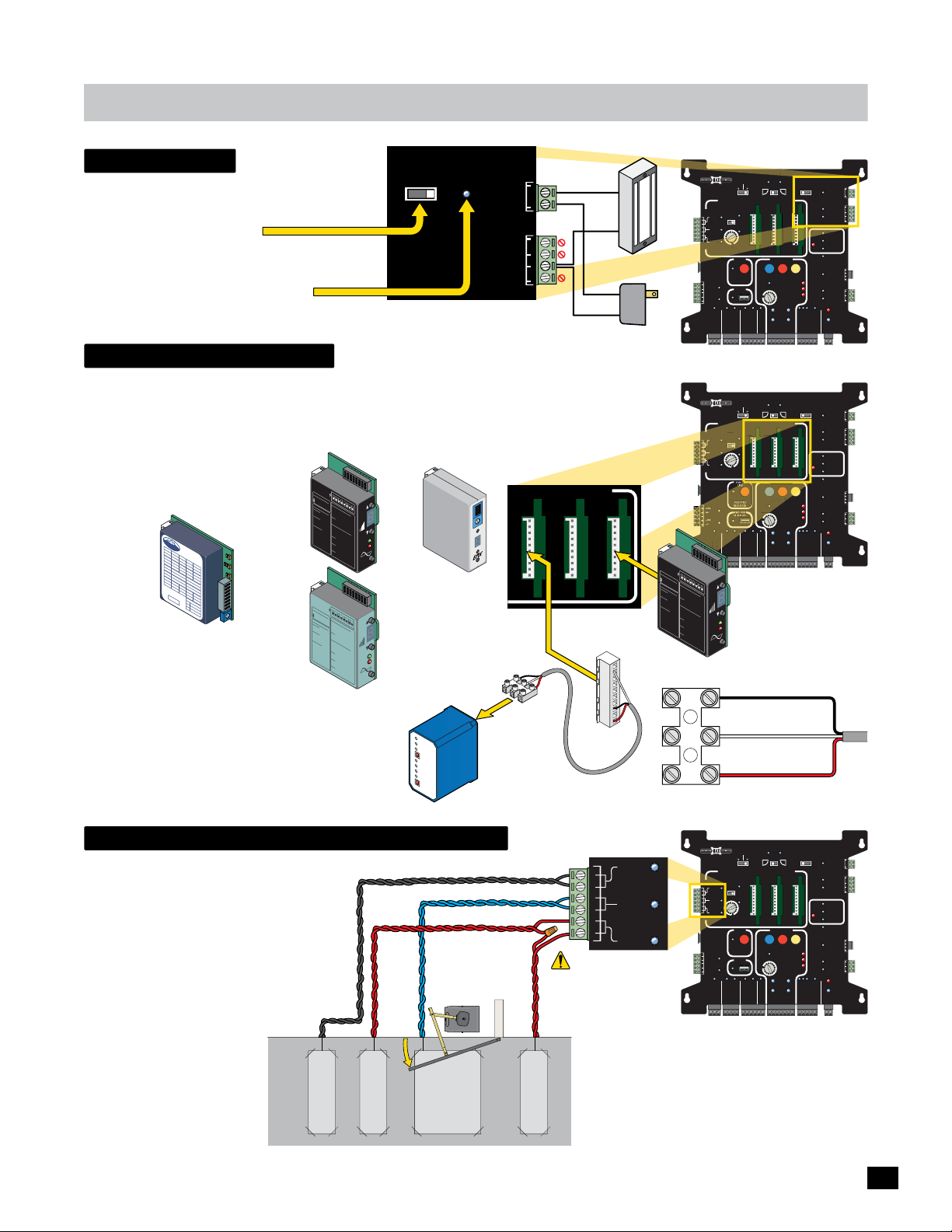
Y
matrix 1
N
MOTION
A
F
R
REN
O
maglock
Maglock MUST be connected as shown.
MAGLOCK DELAY: You MUST select a time
delay when using a maglock.
Maglock power disengages 1.5 sec or
2 sec before gate starts opening.
MAGLOCK LED (Monitors Maglock):
ON - Locked OFF - Unlocked
Flashing - Problem with Maglock Power.
Loop Detectors
MAGLOCK
DELAY
OFF 2Sec1.5Sec
MAG
LOCK
COM
Tamper NO
COM
GND
Tamper IN
NC
Dual Gate Operators: Primary gate
opens FIRST. Install maglock
accordingly to account for this.
Matrix 1 will accept third party loop detectors in the 3 ports. Each loop detector has a
corresponding in-ground loop that must be connected for the loop system to operate
(see below). Power down Matrix 1 BEFORE connecting loop detectors. Refer to your
chosen loop detector’s instruction sheet for specific information about loop detector.
O
N
1
2
OPTIONS
3
4
5
6
7
Plug-In Loop Detectors
Reno
Loop Detector
(Plug-In)
LED always
blinks steadily
operation
during
RENO
A&
E
EX
T
=
SW
0
8
SW 7
DLY=
SW
0
6
SW 5
BO
O
ST
SW 4
M
O
DE
SW 3
F
FREQ
=
SW
LO
2
SW
1
MODEL H2
VE
H
I
CL
E DETECTOR
8-
30 VD
S
EC
O
2
FF
S
E
OF
C5
OFF
F
SE
S
EC
ON
C10 SE
O
O
2
N
F
F
S
OFF
E
OFF
C5
C
ON
OF
F
SE
ON
ON
C10 SE
O
ON
N
OFF
AIL
C
O
N
S
ECUR
ON
OF
EFAIL SAF
F
WNO
OF
O
FON
N
R
ON
M
ON
O
M
E
F
E
FON
OFF
D
O
FF
HI
GH
O
N
OF
F
SE
O
N
F
SITI
C
F
0
V
IT
3
L
Y
O
W
NO
7
RM
H
IG
H
Loop Detector
(Plug-In)
P
OWE
R
DE
T
E
CT
FAIL
12345678
ON
Loop Detector
Low Current
(Plug-In)
EDI
EDI
Draw
EDI
Te
l: 480.968.6407
DEFLECTOME
5 =
Opti
=
Incr
=
Decrea
LED IN
PO
WER
ON
=
OFF= No
DETECT
ON
=
OFF= No
2
Hz Fl
L
oop Faul
1 Flash =
2
F
lashes= Sh
3
Flas
Both LED’s Flashing=
Cu
r
PWR
Pr
evious Lo
EDI
T
el: 480
DEFLECTO
5 = Optim
=
Incr
=
Dec
LE
D IN
POWE
ON
=
OFF=
DETEC
N
ON
=
OFF=
2 Hz Fl
Loop Fau
1 Fl
a
sh = Open L
2
F
lashes
3 Flashe
B
oth
LE
C
urrent
P
WR
L
P
re
v
8
ON
m
T
u
ER
m
e
S
ase Sens
ens.
se Sens
DICA
TORS
Normal
Power
Po
w
Detect
Detect
ash=Delay
Tim
t
Open Lo
hes
or
=2
ted Lo
5% chang
of In
d
u
re
ct
nt Loop Fault
L
ED
Flashing
=
op
F
aul
.968.640
ME
TER
um
e
Se
ase Sens
ns.
r
ease Sens.
DICA
R
TORS
Nor
mal Power
o
Power
T
Detec
N
t
o
Detect
a
s
h=
D
elay
lt
Ti
ming
= Sho
oo
s=
rted
2
5%
L
c
of
hange
In
D’
du
s
Flashin
c
t
anc
Lo
op
ED
g=
Fa
Fl
as
ult
ious
hing=
Loop
F
ault
0
1
2
3
S
W1
4
ON
5
.
SW2 Frequenc
LMA180
6
ON
ON
.
7
=
OFF
8
OF
SENS
Low
F =
OFF
ON
y
Me
=
S
diu
OFF =
W3
Med
m
ON
er
-L
ium-H
Hi
ow
OFF
g
= Fai
h
igh
= Fa
l Secu
S
W4
il Saf
ON
re
SW5 Output
ER
T
e
ON
ON
=
TOME
OFF
ing
OFF =
P
LEC
ulse
F
OFF
B
ON
DE
B
on
=
sa
o
S
p
OFF =
W6
Ent
me as
Puls
ry
ON
op
SENS
e
Loo
on
A
OFF
= 2 Secon
e
p Fault
Exit
ance
= No
S
W7
R
d De
ON
De
l
ay
lay
OFF
POWE
= No
r
=
S
mal
W8
Infi
Pre
ON
t
nite
DETECT
EDI
s
enc
P
OFF
=
r
es
S
e
e
enc
ns
= No
it
e
iv
it
S
y
e
Bo
ns
it
os
iv
t
ity
B
ESET
o
ost
R
O
N
1
2
OPTIONS
3
4
56
7
8
O
N
7
1
2
3
SW1
4
ON
5
.
SW2
LMA1800-LP
6
ON
ON = Low
7
Frequency
OFF
8
OFF = Medium-Lo
SENS
OFF
ON
SW
=
OFF
Me
3
ON
di
=
um-High
High
w
OFF
=
Fail Secure
=
SW4
Fai
ON
l Sa
S
ER
W5
f
e
ON
ON = Pulse
Output
OFF
OFF = B
LECTOMET
OF
B
ON
DEF
F
o
n E
sa
SW
S
=
p
O
m
F
P
ntry
6
F
u
e
oo
l
ON
as
se
=
SEN
p
L
A
o
o
n
OFF
o
=
p
Exi
2
Fau
Sec
t
=
S
W
lt
e
N
on
7
o
d
O
Dela
D
N
WER
e
la
OFF
y
PO
=
y
N
o
T
r
=
S
m
W8
a
In
I
l
fi
P
ON
n
r
i
e
DETEC
te
ED
s
e
P
OFF
=
nce
r
esenc
S
e
nsitiv
=
N
e
o
it
S
y
e
B
nsiti
o
o
s
vi
t
t
y
Bo
o
s
RESET
t
External Loop Detectors
Third party external loop detectors can be used if
desired with the MAX External Loop Detector Cable
Adapter. (1) One is included with the operator but
more can be purchased if needed.
EMX
Loop Detector
(Plug-In)
MAX Part number:
MAX D-TEK
External
Loop
Detector
Connect desired loop detector
to appropriate loop port
OPEN/CLOSE CONTROLS
1234
ON DIP
T
C
E
T
DE
R
E
T
ME
A
TR
UL
ER
W
O
P
T
COUN
Q
RE
F
l
Power
na
mi
r
Te
Wire to
back of
detector
MAX External Loop
Detector Cable Adapter
Pos
Neg
Pos
Neg
SAFETYCENTEREXIT
+
-
Maglock
+
-
Maglock
Power
MATRIX 1
MADE in USA
EXIT
CENTER
SAFETY
SAFET
ID
PLUG
12VDC
GND
24VDC
GND
RADIO SIG.
MATRIX 1
MADE in USA
EXIT
CENTER
ENTE
SAFETY
ID
PLUG
ON
RADIO SIG.
1
2
3
4
5
6
E
T
el:
4
80.968.6407
DEFLEC
5
=
Optim
=
I
n
c
=
re
D
ec
LED
I
PO
NDI
WE
ON
R
=
OF
No
F
=
DETEC
No
ON
T
=
OF
De
F= No
2
H
z
Fl
Loop
a
s
Faul
1
F
l
ash
2
F
l
a
sh
3
Fl
e
a
s
he
B
ot
h
LED’s
C
ur
r
P
e
WR
n
L
ED
P
re
v
i
o
7
8
DI
O
N
TOMETER
1
u
m
2
S
a
ens.
s
e
r
e
a
s
C
rm
P
o
t
ec
Det
h
=Dela
t
=
O
s
=
S
h
s
=25%
o
f
F
l
t
L
oop
Fl
a
us
Lo
1
3
SW1 SW2 Frequ
S
A
e
4
n
s
e
ON
M
5
.
Se
L
6
ns
ON
ON
.
7
AT
OF
= L
8
OF
O
SENS
F
RS
enc
F
o
OF
w
ON
=
y
F
M
al
e
SW3
=
di
OF
P
M
u
ow
F
m
w
e
ON
d
e
er
-L
=
i
r
u
H
ow
m
i
OF
g
=
-Hi
h
F
F
ai
g
=
t
h
l
SW4
F
S
ecure
a
i
e
ON
l
c
SW5 Output
S
t
a
f
e
ON
y
ON
T
i
m
T
OFF
i
C
=
n
OF
E
g
Pu
L
p
F
e
OFF
B
l
n
s
ON
=
DEF
e
L
B s
oop
o
o
n
r
SW6
S
t
=
a
OF
e
E
m
d
Pu
n
F
L
e
t
EN
ry
oo
l
ON
c
s
a
=
S
e
p
s
h
L
o
a
A
Induc
o
nge
n
OF
op
=
E
2
xi
F
Fau
ta
Sec
a
=
t
s
nce
SW7
h
No
in
l
R
t
on
g=
E
d
ON =
Dela
F
De
a
ul
OW
s
t
h
la
OFF
P
y
i
n
y
g=
No
op Fa
r
=
SW8
m
a
I
n
ul
l
TECT
fin
P
ON
t
re
i
DE
t
ED
e
s
ence
Prese
OF
=
S
F
e
=
n
nc
s
No
i
ti
e
v
ity
Se
B
n
oo
s
i
t
s
i
v
t
i
t
y
B
o
o
R
st
Power Terminal
BATTERY
PRIMARY
BACK-UP MODE
GATE
LEAVE
CLOSED
LEAVE
OPEN
OPEN
1 TIME
AUTOMATIC OPEN/CLOSE CONTROLS
ANTI
TAILGATE
OFFON
MAX
MIN
FF
OFF
CLOSE TIMER
PARTIAL
OPEN
POSITION
RECORDER
OBD PORT
BLACK BOX
STRIKE
GND
FIRE DEPT
GND
MAX OPEN
GND
RADIO GND
BATTERY
BACK-UP MODE
LEAVE
CLOSED
LEAVE
OPEN
OPEN
1 TIME
AUTOMATIC OPEN/CLOSE CONTROLS
ANTI
NTI
XIT
TAILGATE
TAILGATE
OFFON
F
MAX
MIN
OFF
CLOSE TIMER
STRIKE
GND
FIRE DEPT
GND
MAX OPEN
GND
RADIO GND
OPTIONS
MAGLOCK
DELAY
OPEN
OPEN
RIGHT
LEFT
OFF
SAFETYCENTEREXIT
MOTOR MOTION
OPEN
STOP CLOSE
REVERSE SENSITIVITY
MAX
GATE SPEED
MOTOR OVERLOAD
MIN
NO LIMIT SWITCH /
CLAMP SLIPPING
MAX
LIMIT
SWITCH
ON-LINE
MOTOR
ON-LINE
PRIMARY
SEC
GATE
GATE
PHOTOCELL
GND
KEYPAD / RDR
GND
OPEN
(+)
GND
(-)
(+)
GND
(-)
PRIMARY
GATE
MAGLOCK
DELAY
OPEN
OPEN
RIGHT
LEFT
OFF
SAFETYCENTEREXIT
MOTOR MOTION
OPEN
STOP CLOSE
PE
REVERSE SENSITIVITY
MAX
MAX
GATE SPEED
MOTOR OVERLOAD
MIN
NO LIMIT SWITCH /
CLAMP SLIPPING
MAX
LIMIT
SWITCH
ON-LINE
MOTOR
ON-LINE
PRIMARY
SEC
GATE
GATE
PHOTOCELL
GND
KEYPAD / RDR
GND
OPEN
(+)
GND
(-)
(+)
GND
(-)
800
R
E
T
E
OM
Plug-In Loop Detector
I
T
SE
E
Com, Gnd (Black)
Loop Detect
Output (White)
Power 15 VDC (Red)
MAG
2Sec1.5Sec
LOCK
COM
NC
Tamper NO
GATE
COM
TAMPER
GND
Tamper IN
PHOTOCELL
UL
EDGE 1
ENTRAP
EDGE 2
ID PLUG
ERROR
UL ALARM 12V
ALARM RET
RESET
GND
OPEN
GATE
COM
STATUS
CLOSE
BATTERY
IN USE
POWER
24V
GND
STOP
CLOSE
COM
GATE DISABLE
MAG
2Sec1.5Sec
LOCK
COM
NC
Tamper NO
GATE
COM
TAMPER
GND
Tamper IN
PHOTOCELL
UL
EDGE 1
ENTRAP
EDGE 2
ID PLUG
ERROR
UL ALARM 12V
ALARM RET
RESET
GND
OPEN
GATE
COM
STATUS
CLOSE
BATTERY
IN USE
POWER
24V
GND
STOP
CLOSE
COM
GATE DISABLE
In-ground loop connection
Connect each in-ground loop wires to the appropriate input. Lead wires
should be twisted together 6 twists per foot
minimum.
See page 14 for in-ground loop installation.
Safety loop wires must be wired in series.
Each LED will light when the corresponding
loop detector get activated by a vehicle
passing over its in-ground loop.
LEDs will flash when
there is an error with the
corresponding loop
Inside Property
EXIT LOOP
SAFETY LOOP
CENTER LOOP
Removable Terminal
EXIT
CENTER
SAFETY
Safety loops need
to be wired in series.
Lead
Wires
Outside Property
SAFETY LOOP
BATTERY
MATRIX 1
BACK-UP MODE
LEAVE
MADE in USA
OPEN
AUTOMATIC OPEN/CLOSE CONTROLS
ANTI
TAILGATE
EXIT
OFFON
CENTER
SAFETY
MIN
MAX
OFF
CLOSE TIMER
PARTIAL
OPEN
ID
PLUG
POSITION
RECORDER
12VDC
GND
OBD PORT
BLACK BOX
24VDC
GND
FIRE DEPT
GND
MAX OPEN
RADIO SIG.
RADIO GND
PRIMARY
GATE
LEAVE
CLOSED
OPEN
1 TIME
STRIKE
GND
GND
MAGLOCK
DELAY
OPEN
OPEN
LEFT
MOTOR MOTION
OPEN
MAX
GATE SPEED
MIN
MAX
PRIMARY
GATE
PHOTOCELL
GND
KEYPAD / RDR
GND
(+)
RIGHT
STOP CLOSE
REVERSE SENSITIVITY
LIMIT
SWITCH
ON-LINE
MOTOR
ON-LINE
GND
(-)
SAFETYCENTEREXIT
MOTOR OVERLOAD
NO LIMIT SWITCH /
CLAMP SLIPPING
SEC
GATE
(+)
MAG
OFF
2Sec1.5Sec
LOCK
COM
NC
Tamper NO
GATE
COM
TAMPER
GND
Tamper IN
PHOTOCELL
UL
EDGE 1
ENTRAP
EDGE 2
ID PLUG
ERROR
UL ALARM 12V
ALARM RET
RESET
GND
OPEN
GATE
COM
STATUS
CLOSE
BATTERY
IN USE
POWER
24V
GND
OPEN
STOP
CLOSE
COM
GATE DISABLE
GND
(-)
detector.
NOTE: Reno H2 detector
always blinks steadily
during normal operation.
29
Page 32
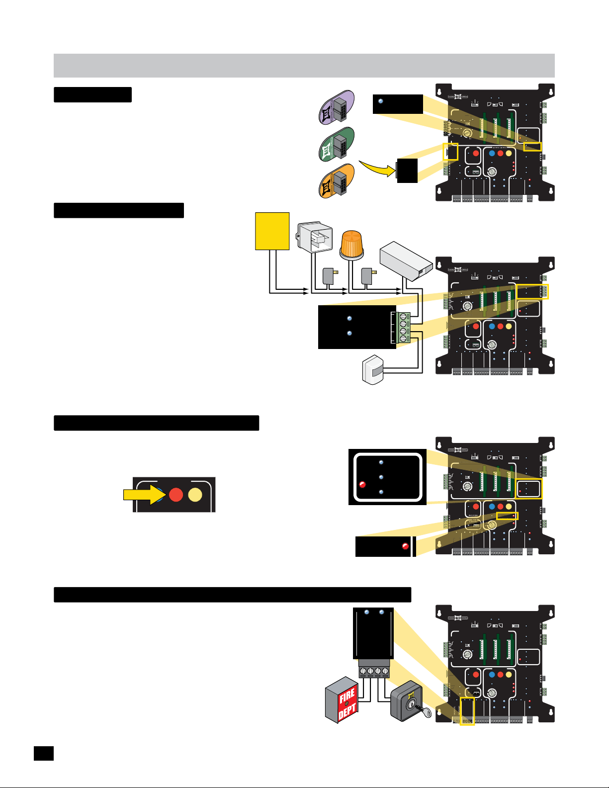
ANTI
matrix 1
ANTI
ND
C
OVERLOAD
CGND
UG
F
id plug
AN ID Plug comes standard on Matrix 1. It identifies the model of
gate operator and MUST be plugged in or the Matrix 1 WILL NOT
function.
Purple is for the MAX Megatron 1400.
Green is for the MAX Megatron 2200.
Orange is for the MAX Megatron FAST.
ID PLUG ERROR LED: Will light when ID PLUG is missing.
RON
T
X
A
M
EGA
M
1400
TRON
X
A
A
G
M
E
M
2200
TRON
X
A
A
G
M
E
M
FAST
MATRIX 1
BATTERY
PRIMARY
BACK-UP MODE
0
40
1
0
20
2
T
S
FA
ID PLUG
ERROR
ID
PLUG
MADE in USA
AUTOMATIC OPEN/CLOSE CONTROLS
TAILGATE
TAILGATE
SAFETY
CLOSE TIMER
ID
PLUG
12VDC
GND
24VDC
GND
RADIO SIG.
RADIO GND
GATE
LEAVE
CLOSED
LEAVE
OPEN
OPEN
1 TIME
ANTI
MIN
OFF
PARTIAL
OPEN
POSITION
RECORDER
OBD PORT
BLACK BOX
STRIKE
GND
FIRE DEPT
GND
MAX OPEN
GND
MAGLOCK
DELAY
OPEN
OPEN
LEFT
OPEN
MAX
GATE SPEED
MIN
MAX
PRIMARY
GATE
PHOTOCELL
GND
KEYPAD / RDR
GND
(+)
RIGHT
LIMIT
SWITCH
ON-LINE
MOTOR
ON-LINE
GND
(-)
SAFETYCENTEREXIT
STOP CLOSE
REVERSE SENSITIVITY
MOTOR OVERLOAD
NO LIMIT SWITCH /
CLAMP SLIPPING
SEC
GATE
(+)
MAG
OFF
2Sec1.5Sec
LOCK
COM
NC
Tamper NO
GATE
COM
TAMPER
GND
Tamper IN
PHOTOCELL
EDGE 1
ENTRAP
EDGE 2
ID PLUG
ERROR
UL ALARM 12V
ALARM RET
RESET
GND
OPEN
GATE
COM
STATUS
CLOSE
BATTERY
IN USE
POWER
24V
GND
OPEN
STOP
CLOSE
COM
GATE DISABLE
GND
(-)
Gate Tamper
The GATE TAMPER can be used for various
functions such as turning a warning light, siren or
camera on when the gate is tampered with
Existing
Building
Alarm
System
(Vandalized Gate). The gate operator defines a
“Vandalized Gate” as UNAUTHORIZED movement
of the gate. This can occur if the red release
handle clamp is lifted and gate is manually moved
from the closed position or the gate is forced
open from the closed position without authorization.
TAMPER NO/Com Relay: Connect a warning light, siren, camera
or an existing alarm system to relay.
TAMPER IN/GND Input: Connect a sensor device to input. When
Tamper In/GND gets triggered, device that is wired to Tamper
relay (NO/Com) will activate.
UL entrapment LEDs
UL ENTRAPMENT LEDs will indicate when a OPENING DIRECTION
Photocell and/or Sensing Edge(s) have been activated. If alarm gets
triggered, press STOP button on Matrix 1 to turn alarm off.
MOTOR MOTION
OPEN STOP CLOSE
NOTE: UL safety approved devices are wired to the MC-200 motor
controllers ONLY. DO NOT wire them to the Matrix 1.
Siren
Power
GATE
TAMPER
Warning
Light
Power
Tamper NO
COM
GND
Tamper IN
Motion
Sensor
PHOTOCELL
UL
ENTRAP
REVERSE SENSITIVITY
Security
EDGE 1
EDGE 2
Camera
BATTERY
MATRIX 1
MADE in USA
AUTOMATIC OPEN/CLOSE CONTROLS
EXIT
CENTER
SAFETY
CLOSE TIMER
D
ID
PL
PLUG
12VDC
GND
24VDC
GND
RADIO SIG.
RADIO GND
TAILGATE
MIN
LOSE TIMER
ANTI
FIRE DEPT
OFF
OF
GND
BACK-UP MODE
LEAVE
OPEN
OFFON
FF
MAX
AX
PARTIAL
OPEN
POSITION
RECORDER
OBD PORT
BLACK BOX
MAX OPEN
PRIMARY
GATE
LEAVE
CLOSED
OPEN
1 TIME
STRIKE
GND
GND
MAGLOCK
DELAY
OPEN
OPEN
LEFT
ENTER
MOTOR MOTION
OPEN
MAX
GATE SPEED
MIN
MAX
PRIMARY
GATE
PHOTOCELL
GND
KEYPAD / RDR
GND
(+)
RIGHT
LIMIT
SWITCH
ON-LINE
MOTOR
ON-LINE
GND
(-)
SAFETYCENTEREXIT
STOP CLOSE
REVERSE SENSITIVITY
MOTOR OVERLOAD
NO LIMIT SWITCH /
CLAMP SLIPPING
SEC
GATE
(+)
MAG
OFF
2Sec1.5Sec
LOCK
GATE
TAMPER
UL
ENTRAP
GATE
STATUS
OPEN
STOP
CLOSE
COM
GATE DISABLE
GND
(-)
NOTE: See page 45 for
more information about
this unique feature.
PRIMARY
BATTERY
MATRIX 1
MADE in USA
AUTOMATIC OPEN/CLOSE CONTROLS
TAILGATE
EXIT
CENTER
SAFETY
CLOSE TIMER
ID
PLUG
12VDC
GND
24VDC
24VD
GND
RADIO SIG.
RADIO GND
MIN
ANTI
FIRE DEPT
OFF
GND
BACK-UP MODE
LEAVE
OPEN
OFFON
MAX
PARTIAL
OPEN
POSITION
MAX OPEN
GATE
LEAVE
CLOSED
OPEN
1 TIME
STRIKE
GND
GND
MAGLOCK
DELAY
OPEN
OPEN
LEFT
ENTER
MOTOR MOTION
OPEN
MAX
GATE SPEED
PRIMARY
GATE
PHOTOCELL
GND
KEYPAD / RDR
GND
(+)
RIGHT
LIMIT
SWITCH
ON-LINE
MOTOR
ON-LINE
GND
(-)
SAFETYCENTEREXIT
STOP CLOSE
REVERSE SENSITIVITY
MOTOR OVERLOAD
NO LIMIT SWITCH /
CLAMP SLIPPING
SEC
GATE
(+)
MAG
OFF
2Sec1.5Sec
LOCK
GATE
TAMPER
UL
ENTRAP
GATE
STATUS
OPEN
STOP
CLOSE
COM
GATE DISABLE
GND
(-)
Tamper NO
Tamper IN
PHOTOCELL
UL ALARM 12V
ALARM RET
24V
Tamper NO
Tamper IN
PHOTOCELL
UL ALARM 12V
ALARM RET
24V
COM
NC
COM
GND
EDGE 1
EDGE 2
ID PLUG
ERROR
RESET
GND
OPEN
COM
CLOSE
BATTERY
IN USE
POWER
GND
COM
NC
COM
GND
EDGE 1
EDGE 2
ID PLUG
ERROR
RESET
GND
OPEN
COM
CLOSE
BATTERY
IN USE
POWER
GND
REVERSE SENSITIVITY LED: Will light when the gate encounters an
obstruction triggering the ERD sensor.
emergency vehicle/max open inputs
PRIMARY
BATTERY
FIRE DEPT lnput: Should be connected to a knox box device to allow
the proper authorities to gain emergency access when necessary. The
input will override the GATE DISABLE input and allow EMERGENCY
personnel FULL 24/7 access. Gate fully opens.
MAX OPEN Input: Can be connected to a key switch and used as an
ADDITIONAL input from the FIRE DEPT input. The input will override
the GATE DISABLE input and allow SECURITY personnel FULL 24/7
access. Gate fully opens.
Knox
Box
FIRE DEPT
GND
MAX OPEN
GND
Key
Switch
MATRIX 1
MADE in USA
AUTOMATIC OPEN/CLOSE CONTROLS
TAILGATE
EXIT
CENTER
SAFETY
CLOSE TIMER
ID
PLUG
12VDC
12VD
GND
24VDC
GND
MIN
ANTI
FIRE DEPT
OFF
GND
BACK-UP MODE
LEAVE
OPEN
OFFON
MAX
PARTIAL
OPEN
POSITION
RECORDER
OBD PORT
BLACK BOX
MAX OPEN
GATE
LEAVE
CLOSED
OPEN
1 TIME
STRIKE
GND
GND
MAGLOCK
DELAY
OPEN
OPEN
LEFT
MOTOR MOTION
OPEN
MAX
GATE SPEED
MIN
MAX
PRIMARY
GATE
PHOTOCELL
GND
KEYPAD / RDR
GND
(+)
RIGHT
LIMIT
SWITCH
ON-LINE
MOTOR
ON-LINE
GND
(-)
SAFETYCENTEREXIT
STOP CLOSE
REVERSE SENSITIVITY
MOTOR OVERLOAD
NO LIMIT SWITCH /
CLAMP SLIPPING
SEC
GATE
(+)
MAG
OFF
2Sec1.5Sec
LOCK
COM
NC
Tamper NO
GATE
COM
TAMPER
GND
Tamper IN
PHOTOCELL
UL
EDGE 1
ENTRAP
EDGE 2
ID PLUG
ERROR
UL ALARM 12V
ALARM RET
RESET
GND
OPEN
GATE
COM
STATUS
CLOSE
BATTERY
IN USE
POWER
24V
GND
OPEN
STOP
CLOSE
COM
GATE DISABLE
GND
(-)
30
Page 33
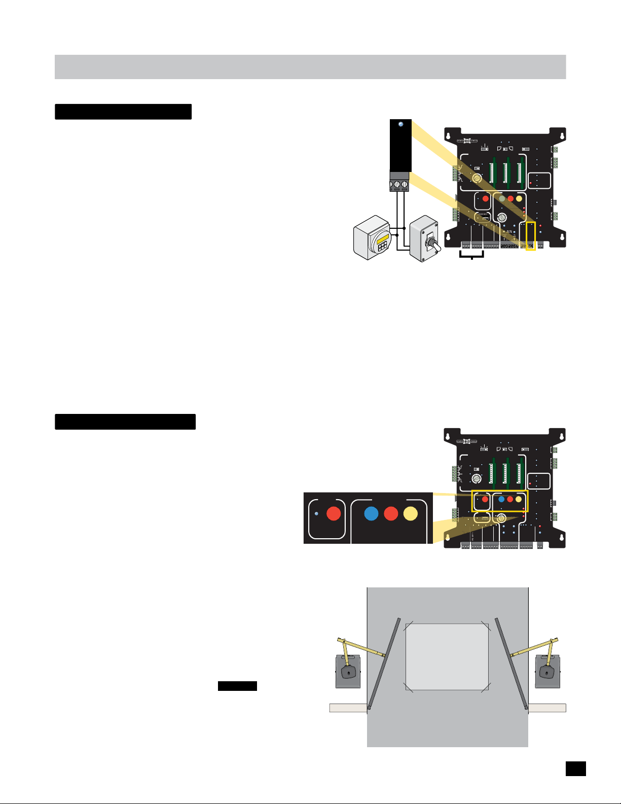
matrix 1
ER
R
WITCH /
C
D
gate disable
PRIMARY
BATTERY
An ON/OFF switch or 7-Day timer devices can be connected to the GATE DISABLE
input. When these devices are turned ON, they will DISABLE normal opening
devices such as keypad, exit loop etc. The FIRE DEPT/ MAX OPEN and RADIO
inputs will remain enabled when GATE DISABLE has been turned ON. This is
useful when the gated area needs to be secured from ALL but emergency or
authorized vehicle entry. Some examples are: Residential home vacation period or
during closed hours of a business when no one can monitor the property.
When GATE DISABLE is turned ON: The operator will beep for 3 minutes
BEFORE arming itself. This allows time to turn ON GATE DISABLE and
leave the property before it is armed.
7-Day
Timer
GND
GATE DISABLE
ON/OFF
Switch
ON
FF
O
MATRIX 1
MADE in USA
AUTOMATIC OPEN/CLOSE CONTROLS
TAILGATE
EXIT
CENTER
ENTE
SAFETY
CLOSE TIMER
ID
PLUG
12VDC
12VD
GND
24VDC
GND
RADIO SIG.
RADIO GND
Enabled inputs when
GATE DISABLE is turned ON.
When FIRE DEPT/MAX OPEN gets activated: Gate opens and GATE TAMPER
relay will activate immediately.
When RADIO Input gets activated: Gate opens and GATE TAMPER relay will activate after 3 min. This allows time to turn OFF
GATE DISABLE or disarm an existing building alarm system if connected.
GATE
BACK-UP MODE
ANTI
MIN
FIRE DEPT
LEAVE
CLOSED
OPEN
LEAVE
1 TIME
OPEN
OFFON
MAX
AX
OFF
PARTIAL
OPEN
POSITION
RECORDER
OBD PORT
STRIKE
GND
KEYPAD / RDR
GND
MAX OPEN
GND
MAGLOCK
DELAY
OPEN
OPEN
LEFT
MOTOR MOTION
OPEN
MAX
GATE SPEED
MIN
MAX
PHOTOCELL
GND
GND
(+)
RIGHT
STOP CLOSE
REVERSE SENSITIVITY
MOTOR OVERLOAD
NO LIMIT SWITCH /
LIMIT
SWITCH
ON-LINE
SAFETYCENTEREXIT
CLAMP SLIPPING
MAG
OFF
2Sec1.5Sec
LOCK
COM
NC
Tamper NO
GATE
COM
TAMPER
GND
Tamper IN
PHOTOCELL
UL
EDGE 1
ENTRAP
EDGE 2
ID PLUG
ERROR
UL ALARM 12V
ALARM RET
RESET
GND
OPEN
GATE
COM
STATUS
CLOSE
BATTERY
IN USE
POWER
24V
GND
OPEN
STOP
CLOSE
COM
GATE DISABLE
NOTE: See page 46 for
more information about
this unique feature.
IMPORTANT: It is NOT recommended activating the GATE DISABLE device while persons are present inside the property.
partial open
PRIMARY
BATTERY
A gate can set to partially open by recording the PARTIAL OPEN gate cycle. LED will stay lit
when PARTIAL OPEN is ON.
IMPORTANT: Limit switches MUST be learned BEFORE Partial Open can be recorded.
PARTIAL
To RECORD PARTIAL OPEN:
OPEN
1. With gate in CLOSED position, press and release PARTIAL OPEN
button to START recording. Blue LED starts flashing.
POSITION
RECORDER
2. Press 3-button station OPEN button to start gate’s open cycle.
3. Press 3-button station STOP button when gate is in desired partial open position (Beyond center loop).
4.
Press PARTIAL OPEN button AGAIN to STOP recording. Blue LED stops flashing,
open position has been recorded. LED remains ON.
To ERASE PARTIAL OPEN recording:
Press and HOLD PARTIAL OPEN button for 5 sec. LED turns OFF.
MOTOR MOTION
OPEN STOP CLOSE
CENTER LOOP
MATRIX 1
MADE in USA
AUTOMATIC OPEN/CLOSE CONTROLS
TAILGATE
EXIT
CENTER
SAFETY
CLOSE TIMER
ID
PLUG
12VDC
GND
24VDC
GND
N
RADIO SIG.
RADIO GND
MIN
ANTI
OFF
GND
BACK-UP MODE
LEAVE
OPEN
OFFON
MAX
PARTIAL
OPEN
POSITION
RECORDER
OBD PORT
BLACK BOX
MAX OPEN
GND
GATE
LEAVE
CLOSED
OPEN
1 TIME
STRIKE
GND
KEYPAD / RDR
MAGLOCK
DELAY
OPEN
OPEN
RIGHT
LEFT
OFF
2Sec1.5Sec
SAFETYCENTEREXIT
TAMPER
UL
ENTRAP
MOTOR MOTION
OPEN
STOP CLOSE
REVERSE SENSITIVITY
MAX
GATE SPEED
MOTOR OVERLOAD
NO LIMIT SWITCH /
STATUS
CLAMP SLIPPING
LIMIT
SWITCH
ON-LINE
MOTOR
ON-LINE
PRIMARY
SEC
GATE
GATE
PHOTOCELL
GND
GND
OPEN
STOP
CLOSE
(+)
GND
(-)
(+)
GND
(-)
MAG
LOCK
COM
NC
Tamper NO
GATE
COM
GND
Tamper IN
PHOTOCELL
EDGE 1
EDGE 2
ID PLUG
ERROR
UL ALARM 12V
ALARM RET
RESET
GND
OPEN
GATE
COM
CLOSE
BATTERY
IN USE
POWER
24V
GND
COM
GATE DISABLE
CAUTION: Gates partial OPEN
position MUST be outside the
NOTE: The FIRE DEPT and/or MAX
OPEN connected devices will always
Center Loop when in-ground
loops have been installed.
FULLY open gates even when the
partial open is being used.
31
Page 34
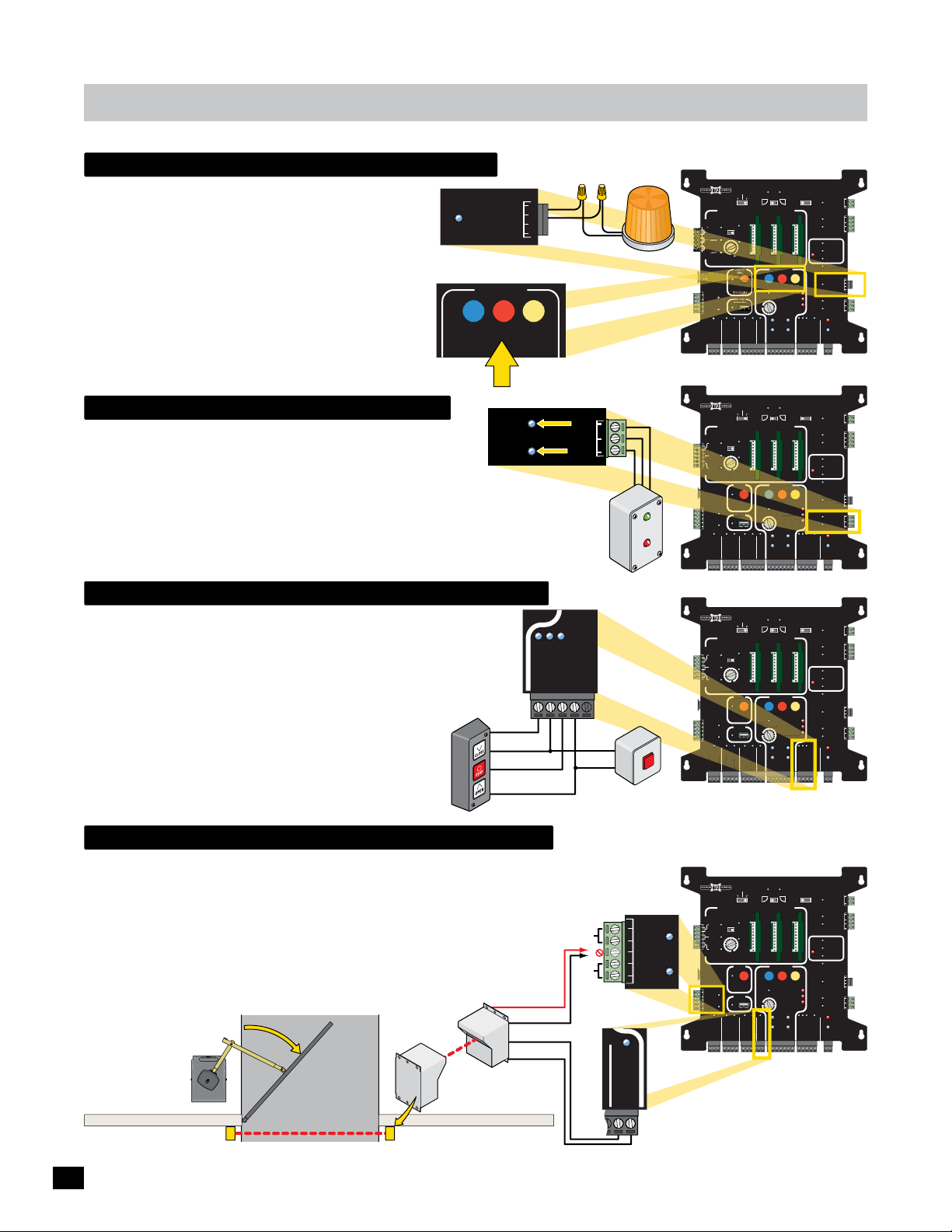
matrix 1
ORPENTO
C
D
ALAR
DLOS
R
F
Y
D
R
G
T
/
G
/
G
N
E
D
E DEPT
D
UL alarm / Alarm shut-off
A UL ALARM (strobe light) can be connected. It will turn
ON when the GATE IN MOTION - Mode 0 and/or Mode 1
are turned ON (see page 28).
Press STOP BUTTON to Shut-OFF activated strobe light.
Press STOP BUTTON to Shut-OFF an activated alarm.
STROBE LIGHT NOTE: 12VDC - 250 mA max.
UL ALARM 12V
ALARM RET
RESET
GND
MOTOR MOTION
OPEN
STOP
gate status monitoring
GATE STATUS LEDs will turn ON when gate is in the OPEN or
GATE
STATUS
CLOSED position.
Connect a gate monitoring device to GATE STATUS relays to show
if gate is in the OPEN or CLOSED position.
OPEN/COM Relay: Activates when gate gets to the OPEN position.
CLOSE/COM Relay: Activates when gate gets to the CLOSED
position.
in Remote Location
open / stop / close Connection
The OPEN/STOP/CLOSE inputs will allow a standard 4-wire 3-Button
Station and a External Alarm RESET Button to be connected.
Corresponding LEDs will light when each button is activated.
External Alarm Reset Button
An external Alarm Reset button needs to be installed in
a secure place and connected as shown to quickly
SHUT-OFF a sounding alarm. Otherwise alarm can only
be shut-off by the STOP BUTTON on the Matrix 1 (see
Alarm Shut-Off above).
3-Button
Station
OPEN
STOP
CLOSE
Com
CLOSE
OPEN
COM
CLOSE
Remote Gate
Monitoring Device
OPEN
STOP
CLOSE
COM
GATE DISABLE
STOP
Com
Strobe
Light
TE OPEN
A
G
D
TE CLOSE
GA
S
PRES
to RESET
External Alarm
Reset Button
BATTERY
MATRIX 1
BACK-UP MODE
LEAVE
MADE in USA
OPEN
AUTOMATIC OPEN/CLOSE CONTROLS
ANTI
TAILGATE
EXIT
OFFON
MIN
OFF
CLOSE TIMER
POSITION
12VDC
GND
24VDC
24VD
GND
N
FIRE DEPT
GND
MAX OPEN
RADIO SIG.
RADIO GND
BATTERY
MATRIX 1
BACK-UP MODE
LEAVE
MADE in USA
OPEN
AUTOMATIC OPEN/CLOSE CONTROLS
ANTI
TAILGATE
EXIT
OFFON
CENTER
ENTE
SAFETY
SAFET
MAX
MIN
OFF
F
CLOSE TIMER
LOSE TIMER
PARTIAL
OPEN
ID
PLUG
PLU
POSITION
RECORDER
ECORDE
12VDC
GND
BD POR
OBD PORT
BLACK BOX
24VDC
GND
FIRE DEPT
GND
MAX OPEN
RADIO SIG.
RADIO GND
BATTERY
MATRIX 1
BACK-UP MODE
LEAVE
MADE in USA
OPEN
AUTOMATIC OPEN/CLOSE CONTROLS
ANTI
TAILGATE
EXIT
OFFON
CENTER
SAFETY
MAX
MIN
OFF
CLOSE TIMER
PARTIAL
OPEN
ID
PLUG
POSITION
RECORDER
12VDC
GND
OBD PORT
BLACK BOX
24VDC
GND
FIRE DEPT
GND
MAX OPEN
RADIO SIG.
RADIO GND
PRIMARY
GATE
LEAVE
CLOSED
OPEN
1 TIME
STRIKE
GND
GND
LEAVE
CLOSED
OPEN
1 TIME
ITION
STRIKE
GND
GND
LEAVE
CLOSED
OPEN
1 TIME
PE
NDN
TRIK
STRIKE
GND
GND
MAGLOCK
DELAY
OPEN
OPEN
LEFT
MOTOR MOTION
OPEN
MAX
GATE SPEED
MIN
MAX
PRIMARY
GATE
PHOTOCELL
GND
KEYPAD / RDR
GND
(+)
PRIMARY
GATE
OPEN
LEFT
MOTOR MOTION
MOTOR MOTION
OPEN
MAX
MAX
GATE SPEED
ATE SPEE
MIN
IN
MAX
PRIMARY
GATE
PHOTOCELL
GND
KEYPAD / RDR
GND
(+)
PRIMARY
GATE
OPEN
LEFT
MOTOR MOTION
OPEN
MAX
GATE SPEED
MIN
MAX
PRIMARY
GATE
PHOTOCELL
GND
KEYPAD / RDR
GND
(+)
RIGHT
LIMIT
SWITCH
ON-LINE
MOTOR
ON-LINE
GND
(-)
OPEN
RIGHT
LIMIT
SWITCH
ON-LINE
MOTOR
ON-LINE
GND
(-)
OPEN
RIGHT
LIMIT
SWITCH
ON-LINE
MOTOR
ON-LINE
GND
(-)
SAFETYCENTEREXIT
STOP CLOSE
P
REVERSE SENSITIVITY
MOTOR OVERLOAD
NO LIMIT SWITCH /
CLAMP SLIPPING
SEC
GATE
(+)
SAFETYCENTEREXIT
STOP CLOSE
REVERSE SENSITIVITY
MOTOR OVERLOAD
NO LIMIT SWITCH /
O LIMIT SWITCH
CLAMP SLIPPING
LAMP SLIPPIN
SEC
GATE
(+)
SAFETYCENTEREXIT
STOP CLOSE
REVERSE SENSITIVITY
MOTOR OVERLOAD
NO LIMIT SWITCH /
O LIMIT SWITCH
CLAMP SLIPPING
LAMP SLIPPIN
SEC
GATE
(+)
MAG
2Sec1.5Sec
OFF
LOCK
COM
NC
Tamper NO
GATE
COM
TAMPER
GND
Tamper IN
PHOTOCELL
UL
EDGE 1
ENTRAP
EDGE 2
ID PLUG
RR
ERROR
UL ALARM 12V
ALARM RET
RESET
GND
OPEN
GATE
COM
STATUS
CLOSE
BATTERY
IN USE
POWER
24V
GND
OPEN
STOP
CLOSE
COM
GATE DISABLE
GND
(-)
MAGLOCK
DELAY
MAG
OFF
2Sec1.5Sec
LOCK
COM
NC
Tamper NO
GATE
COM
TAMPER
GND
Tamper IN
PHOTOCELL
UL
EDGE 1
ENTRAP
EDGE 2
ID PLUG
ERROR
UL ALARM 12V
ALARM RET
RESET
E
GND
N
OPEN
GATE
COM
STATUS
CLOSE
BATTERY
IN USE
POWER
24V
GND
OPEN
STOP
CLOSE
COM
GATE DISABLE
GND
(-)
MAGLOCK
DELAY
MAG
OFF
2Sec1.5Sec
LOCK
COM
NC
Tamper NO
GATE
COM
TAMPER
GND
Tamper IN
PHOTOCELL
UL
EDGE 1
ENTRAP
EDGE 2
ID PLUG
ERROR
UL ALARM 12V
ALARM RET
RESET
GND
OPEN
GATE
COM
STATUS
CLOSE
BATTERY
IN USE
POWER
24V
GND
OPEN
STOP
CLOSE
COM
GATE DISABLE
GND
(-)
closing photocell connection
The Normally OPEN PHOTOCELL input will allow a CLOSING DIRECTION
Normally OPEN PHOTOCELL to be connected. 12V or 24V power can be
supplied for the photocells.
IMPORTANT: This input is NOT UL 325 entrapment protection.
NOTE: This input is typically used when an existing normally open
photocell needs to be retro-fitted to this operator when this
operator is replacing an obsolete operator.
INSIDE Property
CLOSING
GATE
DIRECTION
OUTSIDE Property
12V or 24V
Photocells
Choose 12 VDC OR 24 VDC
(250 mA Max.)
Power
GND
N.O.
GND
PHOTOCELL
12VDC
GND
24VDC
GND
GND
BATTERY
MATRIX 1
MADE in USA
AUTOMATIC OPEN/CLOSE CONTROLS
EXIT
CENTER
SAFETY
CLOSE TIMER
ID
D
PLUG
PLUG
12VDC
GND
24VDC
GND
N
RADIO SIG.
RADIO GND
TAILGATE
MIN
ANTI
FIRE DEPT
OFF
GND
BACK-UP MODE
LEAVE
OPEN
OFFON
MAX
PARTIAL
OPEN
POSITION
RECORDER
OBD PORT
BLACK BOX
MAX OPEN
PRIMARY
GATE
LEAVE
CLOSED
OPEN
1 TIME
STRIKE
GND
GND
MAGLOCK
DELAY
OPEN
OPEN
LEFT
MOTOR MOTION
OPEN
MAX
GATE SPEED
MIN
MAX
PRIMARY
GATE
PHOTOCELL
GND
KEYPAD / RDR
GND
(+)
RIGHT
LIMIT
SWITCH
ON-LINE
MOTOR
ON-LINE
GND
(-)
SAFETYCENTEREXIT
STOP CLOSE
REVERSE SENSITIVITY
MOTOR OVERLOAD
NO LIMIT SWITCH /
CLAMP SLIPPING
SEC
GATE
(+)
MAG
OFF
2Sec1.5Sec
LOCK
GATE
TAMPER
UL
ENTRAP
UL ALARM 12V
GATE
STATUS
OPEN
STOP
CLOSE
COM
GATE DISABLE
GND
(-)
Additional CLOSING Cycle
Photocells can be connected.
Tamper NO
Tamper IN
PHOTOCELL
ALARM RET
24V
COM
NC
COM
GND
EDGE 1
EDGE 2
ID PLUG
ERROR
RESET
GND
OPEN
COM
CLOSE
BATTERY
IN USE
POWER
GND
32
Page 35
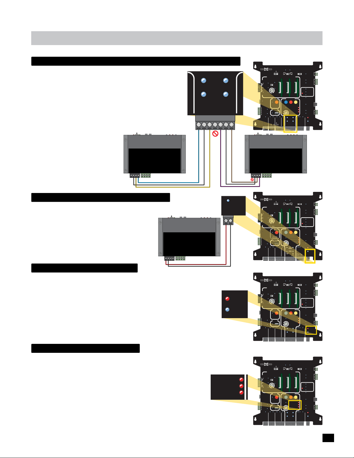
matrix 1
D
R
G
G
USPENTO
R
IT SWITCH /
F
US
CND
F
CND
gate operators communication leds
PRIMARY operator’s MC-200 has been wired to the
PRIMARY GATE (Factory Wired).
SECONDARY operator’s MC-200 gets connected to the
SEC GATE (+, GND, -). See page 22.
LIMIT SWITCH ON-LINE LEDs: will light for each gate
PRIMARY
GATE
(+)
GND
LIMIT
SWITCH
ON-LINE
MOTOR
ON-LINE
(-)
SEC
GATE
(+)
operator’s limit switch that the Matrix 1 is successfully
communicating with.
MOTOR ON-LINE LEDs: will light for
each gate operator’s MC-200 Motor
Controller that the Matrix 1 is
successfully communicating with.
RS-485 (-) -
PWR 24V -
GND -
BOARD
MATRIX
RS-485 (+) -
PWR 12V -
Primary
MAX MC-200
not used -
not used -
GND -
INPUTS
PACK
SWITCH
MOTOR
BATTERY
ALARM
LIMIT
Factory Wired
Power In
MOTOR
24V power for matrix 1
24VDC POWER from PRIMARY operator ONLY.
POWER LED: Will light when 24V low voltage power is
connected.
NOTE: DO NOT power any external devices using this
connection. This power is reserved for Matrix 1 ONLY.
battery in use led
RS-485 (+) -
RS-485 (-) -
PWR 24V -
GND -
BOARD
MATRIX
Primary
MAX MC-200
PWR 12V -
not used -
not used -
GND -
PACK
SWITCH
BATTERY
LIMIT
ALARM
Factory Wired
INPUTS
Power In
MOTOR
MOTOR
24V
BATTERY IN USE LED will light when operator is using ONLY battery
back-up power. The GATE IN MOTION Alarm can be set up to sound alarm
when operator is using ONLY battery power DURING gate cycling. This
brings to attention that only battery power is being used and NOT normal
AC power. See page 28.
LED Flashing NOTE: BATTERY IN USE and POWER LEDs flash together
when the battery is not plugged into the BATTERY IN port of the MAX BC-7
Battery Module. Make sure battery plug is correctly installed and there is no
damaged or loose wires.
GND
24V
(-)
RS-485RS-485
POWER
GND
BATTERY
IN USE
POWER
RS-485 (+) -
RS-485 (-) -
PWR 24V -
GND -
MATRIX 1
LU
PLUG
12VDC
GND
24VDC
GND
BOARD
MATRIX
PWR 12V -
MATRIX 1
ID
D
PLUG
LU
12VDC
GND
24VDC
GND
MATRIX 1
ID
PLUG
12VDC
GND
24VDC
24VD
GND
BATTERY
PRIMARY
BACK-UP MODE
GATE
LEAVE
CLOSED
OPEN
OPEN
LEAVE
MADE in USA
AUTOMATIC OPEN/CLOSE CONTROLS
EXIT
CENTER
SAFETY
AFETY
RADIO SIG.
TAILGATE
CLOSE TIMER
RADIO GND
LEFT
1 TIME
OPEN
ANTI
OFFON
MAX
MIN
OFF
PARTIAL
MOTOR MOTION
PEN
OPEN
OPEN
ITION
POSITION
ECORDE
RECORDER
MAX
ATE SPEE
GATE SPEED
OBD PORT
BLACK BOX
MIN
IN
MAX
PRIMARY
GATE
PHOTOCELL
GND
KEYPAD / RDR
GND
FIRE DEPT
MAX OPEN
(+)
GND
Secondary
MAX MC-200
not used -
not used -
GND -
MADE in USA
AUTOMATIC OPEN/CLOSE CONTROLS
TAILGATE
EXIT
CENTER
ENTE
SAFETY
AFETY
RADIO SIG.
RADIO GND
MADE in USA
AUTOMATIC OPEN/CLOSE CONTROLS
TAILGATE
EXIT
CENTER
SAFETY
AFETY
MIN
CLOSE TIMER
LOSE TIMER
RADIO SIG.
RADIO GND
ANTI
FIRE DEPT
ANTI
IN
FIRE DEPT
GND
OFF
GND
BATTERY
BACK-UP MODE
LEAVE
OPEN
OFFON
MAX OPEN
BATTERY
BACK-UP MODE
LEAVE
OPEN
OFFON
MAX
AX
F
PARTIAL
OPEN
POSITION
RECORDER
OBD PORT
BLACK BOX
MAX OPEN
INPUTS
PACK
SWITCH
MOTOR
BATTERY
ALARM
LIMIT
PRIMARY
GATE
LEAVE
CLOSED
OPEN
OPEN
LEFT
1 TIME
MOTOR MOTION
OPEN
MAX
GATE SPEED
MAX
PHOTOCELL
GND
STRIKE
GND
KEYPAD / RDR
GND
GND
(+)
GND
PRIMARY
GATE
LEAVE
CLOSED
OPEN
OPEN
LEFT
1 TIME
MOTOR MOTION
PEN
OPEN
PENTOP
MAX
GATE SPEED
MIN
MAX
PRIMARY
GATE
PHOTOCELL
GND
STRIKE
GND
KEYPAD / RDR
GND
GND
(+)
GND
OPEN
RIGHT
STOP CLOSE
REVERSE SENSITIVITY
LIMIT
SWITCH
ON-LINE
MOTOR
ON-LINE
(-)
OPEN
RIGHT
STOP CLOSE
REVERSE SENSITIVITY
EVERSE SENSITIVITY
(-)
OPEN
RIGHT
STOP CLOSE
REVERSE SENSITIVITY
EVERSE SENSITIVITY
LIMIT
SWITCH
N-LINE
ON-LINE
MOTOR
ON-LINE
(-)
SAFETYCENTEREXIT
MOTOR OVERLOAD
NO LIMIT SWITCH /
CLAMP SLIPPING
SEC
GATE
(+)
SAFETYCENTEREXIT
P
MOTOR OVERLOAD
NO LIMIT SWITCH /
CLAMP SLIPPING
SAFETYCENTEREXIT
MOTOR OVERLOAD
NO LIMIT SWITCH /
CLAMP SLIPPING
SEC
GATE
(+)
MAGLOCK
DELAY
MAG
OFF
2Sec1.5Sec
LOCK
COM
NC
Tamper NO
GATE
COM
TAMPER
GND
Tamper IN
PHOTOCELL
UL
EDGE 1
ENTRAP
EDGE 2
ID PLUG
ERROR
UL ALARM 12V
ALARM RET
RESET
GND
OPEN
GATE
COM
STATUS
CLOSE
BATTERY
IN USE
POWER
24V
GND
OPEN
STOP
CLOSE
COM
GATE DISABLE
GND
(-)
Power In
MOTOR
MAGLOCK
DELAY
MAG
OFF
2Sec1.5Sec
LOCK
COM
NC
Tamper NO
GATE
COM
TAMPER
GND
Tamper IN
PHOTOCELL
UL
EDGE 1
ENTRAP
EDGE 2
ID PLUG
ERROR
UL ALARM 12V
ALARM RET
RESET
GND
OPEN
GATE
COM
STATUS
TAT
CLOSE
BATTERY
IN USE
POWER
24V
GND
GATE DISABLE
MAGLOCK
DELAY
MAG
OFF
2Sec1.5Sec
LOCK
COM
NC
Tamper NO
GATE
COM
TAMPER
GND
Tamper IN
PHOTOCELL
UL
EDGE 1
ENTRAP
EDGE 2
ID PLUG
ERROR
UL ALARM 12V
ALARM RET
RESET
GND
OPEN
GATE
ATE
COM
STATUS
TAT
CLOSE
BATTERY
IN USE
POWER
24V
GND
OPEN
STOP
CLOSE
COM
GATE DISABLE
GND
(-)
motor motion leds
REVERSE SENSITIVITY LED: Will light when the gate encounters an obstruction triggering
the ERD sensor.
MOTOR OVERLOAD LED: Will light when excessive current is being drawn
by motor caused by damaged gate hardware or gate is too heavy.
NO LIMIT SWITCH/CLAMP SLIPPING LED: Will light when either limit switch
REVERSE SENSITIVITY
MOTOR OVERLOAD
NO LIMIT SWITCH /
CLAMP SLIPPING
does NOT activate from it’s learned positions.
NO LIMIT SWITCH/CLAMP SLIPPING LED: Will light when the release handle clamp is
slipping on the output shaft. The learned gate OPEN and CLOSE positions will NOT be correct
when the limit tabs keep changing position.
MATRIX 1
MADE in USA
AUTOMATIC OPEN/CLOSE CONTROLS
EXIT
CENTER
SAFETY
SAFETY
CLOSE TIMER
ID
PLUG
12VDC
12VD
GND
24VDC
GND
RADIO SIG.
RADIO GND
TAILGATE
MIN
LOSE TIMER
ANTI
FIRE DEPT
OFF
GND
BATTERY
BACK-UP MODE
LEAVE
OPEN
OFFON
MAX
F
PARTIAL
OPEN
POSITION
RECORDER
OBD PORT
LACK BOX
BLACK BOX
MAX OPEN
PRIMARY
GATE
LEAVE
CLOSED
OPEN
1 TIME
PEN
STRIKE
GND
GND
MAGLOCK
DELAY
OPEN
OPEN
LEFT
MOTOR MOTION
OPEN
MAX
GATE SPEED
MIN
IN
MAX
PRIMARY
GATE
PHOTOCELL
GND
KEYPAD / RDR
GND
(+)
RIGHT
LIMIT
SWITCH
ON-LINE
MOTOR
ON-LINE
GND
(-)
SAFETYCENTEREXIT
STOP CLOSE
REVERSE SENSITIVITY
MOTOR OVERLOAD
NO LIMIT SWITCH /
CLAMP SLIPPING
SEC
GATE
(+)
MAG
OFF
2Sec1.5Sec
LOCK
COM
NC
Tamper NO
GATE
COM
TAMPER
GND
Tamper IN
PHOTOCELL
UL
EDGE 1
ENTRAP
EDGE 2
ID PLUG
ERROR
UL ALARM 12V
ALARM RET
RESET
GND
OPEN
GATE
COM
STATUS
CLOSE
BATTERY
IN USE
POWER
24V
GND
OPEN
STOP
CLOSE
COM
GATE DISABLE
GND
(-)
33
Page 36
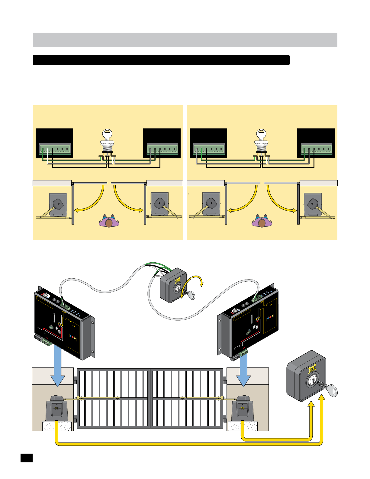
matrix 1
external Open/Close key switch - optional
An Optional External Open/Close Key Switch can be connected that allows dual gate operators to be electronically moved
open or closed at the same time by wiring both operators to the external key switch.
Connect (3) three wires from each MAX MC-200 Motor Controllers to an External Open/Close Key Switch depending on your
specific installation, see below.
Primary
MAX MC-200
Motor Controller
GND
Cell
Jog RT
Edge 1
Edge 2
Photo
Jog LT
PRIMARY
OPEN LEFT
Ov
Mo
er
tor
L
oad
ERD
Sens
ER
D
it
iv
i
t
5
y
1
4
2
13
3
1
4
1
1
C
5
6
AUTI
A
TTE
MC-200 Swing
•
A
o
p
•
Wi
M
o
p
a
re u
•
R
e
b
e
•
M
p
o
•
U
N
J
U
M
PWR 24V -
JOG
MA
LE
L
O
E
D
N
F
X
T
O
:
S
N
e
:
m
s
U
ST
I
L
A
C
A
IT
e
i
Vo
e
o
r
L
N
L
LY
sen
2
g
e
N
Y
1
O
u
t
s
o
r
PWR 12V
-
J
O
RIGHT
G
n
st
a
ll
a
tio
i
r
n
la
i
n
n
st
o
t
ice
d
’
i
n
t
P
r
Gu
ot
ec
id
t
el
b
e
ine
w
i
r
OT
e
d
to
f
u
E
n
ct
i
o
C
n
LOSED
.
so
r
s
0
(
0
ON
w
LY,
h
e
n
d
u
a
a
n
d
/
o
r
o
Ph
f
t
h
o
e
t
o
3
2
V
In
M
p
u
U
R
ST
ED
b
se
e
n
M
so
U
r
s.
ST
fa
u
r
l
e
t
main
w
i
l
l
occ
u
MC
2
ON
LY
s
GND
e
p
nsor
-
-
-
LT
g
ruct
n
st
a
ion
s
D
GE
N
.
C
t
o
e
l
o
p
e
C
e
t
s.
u
se
d
r
.
0
0
P
owe
s
with
AL
AR
RT
Jo
g
ion
Jo
GND
s.
ll
a
.
)
a
ra
l
l
ca
to
W
r
Edge
t
i
o
1
o
ch
to
n
G
ND
R
e
nt
M
M
Edge
n
.
-
-
L
-
i
m
1
i
t
S
W
2
3
r
Jog LT
E
n
Jog RT
tr
In
ap
GND
p
m
uts
u
e
nus
:
Edge 2
MUST
Edge 1
ed
Mo
i
np
r
ni
s
Photo Cell
t
R
o
eversi
Inpu
r
ed
ts
E
to MON
dge
&
2
n
g
T
3
o
ITOR
LE
O
A
1
R
Mo
.
M
R
N
O
in
n
w
N
I
i
T
t
Phot
i
o
O
re
l
R
r
d
ed
E
t
e
o
a
o
Cell
rn
i
j
n
p
e
u
u
d
m
.
A
p
2
n
e
.
y
Reve
re
3
2
1
d.
b
rsi
e
ng
w
3. P
Ed
i
re
d
re
to e
b
ss
a
u
nd
t
t
u
on
H
s
n
t
at t
i
l
1
b
h
e
2
e
V
p
i
M
s
U
ST
b
e
u
se
d
rap
L
O
me
C
e
P
a
-2
b
rn
EN
nt
0
mo
y
0
p
b
PW
d
4
e
ro
e
.
e
L
p
te
E
i
n
R
D
se
c
g
s
.
t
1
i
WI
o
2
n
V
n
f
L
so
L
r
o
r
o
n MC
B
L
o
IM
O
TH
p
IT
SW
e
ra
5
M
.
IT
t
P
o
BA
CH
rs
re
TT
to
ss
a
r
E
S
RY
T
PA
l
ea
b
O
C
r
P
n
e
K
e
se
In
p
MO
i
n
n
s
g st
pu
T
O
I
t
NP
o
s are
R
p
U
T
n
S
o
Power
I
n
NTI
O
N
E
n
tr
ap
Sen
sen
so
e
r
ra
M
t
o
r
W
r
e
N
O
ON
R
M
I
TO
e
R
ra
ED
t
o
r
’
s
se
M
d
.
ve
r
si
n
w
g
ired
Ed
t
C
o
-2
0
0
w
PWR
e
r
M
ON
U
SED
M
inp
P
ER
E
D
A
TR
I
X 1
RS-485 (-) -
RS-485 (+) -
GND -
Key Switch
Open
Terminal
Close
Terminal
Gnd Gnd
OUTSIDE Property
INSIDE Property
Primary Open LEFT
22 AWG Min.
3-conductor twisted
pair, shielded cable
1
2
o
l
Phot
Cel
MA
O
TRI
N
LIN
X
E
E
d
1
g
e
M
U
2
L
otor
E
MC
n
E
t
d
r
a
Co
g
p
e
-200
P
P
ntr
h
o
OW
t
o
oll
Ce
er
E
l
l
R
nt
P
r
ot
ectio
j
um
u
t
s
per
n
MU
ST be
s
e
ns
“L
o
puts
r
s
E
.
A
R
2
N
D
&
S
ED
e
3
n
”
t
:
so
s
B
rs
E
MU
FO
u
n
u
ST
R
se
E
t
d
be
h
i
ey
n
p
u
ca
g
t
s
e
n
M
a
b
n
U
i
e
t
d
h
ST
/or P
e
r
be
i
n
O
p
h
L
u
o
D
t
to
t
2
e
h
C
sa
o
e
e
r
l
O
3
l
m
.
ca
P
he
e ti
EN
n
a
m
r
d
&
e
,
MO
l
o
STO
e
n
T
a
O
M
rn
R
P
m
M
a
O
tr
TI
o
i
O
x
d
N
e
1
b
e
gi
n
s.
S
T
OP
l
a
st
C
L
s for 5 m
O
SE
b
i
e O
n
.
i
n
N
d
i
f
ca
or
2
0
t
e
0
e
C
a
.
d
-
ch
L
2
E
00
D
d
e
s
e
s
u
t
w
e
WI
se
h
ct
e
d
LL
e
n
.
b
d
u
d
b
t
u
t
e
o
a
n
O
l
ors a
N
a
g
a
n
s.
i
n
d
w
e
n
i
t
h
d l
w
i
n
M
ea
5
O
rn
m
N
i
m
n
I
T
o
O
d
R
e
,
E
D
.
M
OT
O
R
.
Secondary
MAX MC-200
Motor Controller
Secondary
MAX MC-200
Motor Controller
GND
Cell
Edge 1
Edge 2
Key Switch
Photo
OPEN
Jog LT
Jog RT
SECONDARY
OPEN RIGHT
MAX External Open/Close
Secondary
MAX MC-200
Motor Controller
GND
Jog LT
Edge 1
Edge 2
Jog RT
SECONDARY
OPEN LEFT
IMPORTANT:
The External Open/Close Key Switch WILL override
GATE DISABLE switch/timer device when turned
ON but the GATE TAMPER relay WILL be activated.
CLOSE
Primary
MAX MC-200
Motor Controller
Cell
Photo
Open
Terminal
Key Switch
Close
Terminal
OUTSIDE Property
INSIDE Property
Primary Open RIGHT
r
e
l
l
-200
ro
t
C
n
M
Co
r
to
p
WER
a
r
O
Mo
nt
P
E
L
U
ge
ell
d
C
E
o
IX
t
o
E
TR
N
I
Ph
1
L
MA
n
ge
N-
to
Cell
d
2
O
o
2
E
h
e
P
1
e
g
D
N
G
RT
g
LT
Jo
g
Jo
G
JO
IGHT
R
G
T
JO
EF
L
D
X
N
ivity
R
A
t
O
E
si
M
n
4
3
5
LED
Se
ns.
o
i
6
ct
1
.
u
d
r
on
15
tor
a
o
L
Mo
r
ve
O
i
st
t
4
n
a
i
1
ll
3
n
a
1
12
o
i
st
in
lat
’
l
d
D
a
st
ce
n
ER
i
ti
o
e
n
la
n
Se
:
r
i
tio
Vo
:
ec
TION
r
N
o
Mo
U
ot
s
O
1
e
A
Pr
TI
n
C
ATTE
MC-200 Swing
A
•
o
Wir
•
MON
o
a
R
•
b
MC-
•
p
U
•
J
M
PWR 24V -
ev
i
t
N
GE
R
n
el
id
ED
me
to
Edge
Gu
.
ap
ed
r
n
r
i
tr
)
o
.
io
n
w
C
ct
.
e
E
n
ch
O
b
a
(N
fu
e
Sens
ST
ors
o
t
t
OT
U
a
,
r
N
M
or
e
t
LY
p
LOSED
or
LL
o
ni
I
s
C
l
n
W
e
ua
s ON
Mo
r
o
LY
s
r
d
o
L
t
n
n
so
a
r
hot
ca
MA
he
P
sen
pe
R
w
ell
l
O
0
C
el
N
ED
20
to
C
R
e
o
.
s
TO
t
MC-
I
Ph
u
r
s
to
p
’
o
r
/
n
d
I
o
t
nd
a
se
3
a
3
.
u
e
d
h
e
per
t
2
ge
b
f
o
use
1
Ed
e
ST
Y
s.
r
G
N
D
U
N
ng
sor
A
M
si
r
n
o
V
t
ve
2
se
b
d
e
ain
1
e
m
ED
e
wir
r.
R
r
u
e
PWR
MUST
TO
ST
cc
0
I
V
o
U
0
l
2
il
M
12
w
s
MON
R
t
t
l
r
u
pu
e
PW
n
fa
w
i
r
0
o
o
0
pr
2
t
-
SED
n
C
ED
U
M
N
pme
PER
PWR
ra
M
t
0
n
U
0
e
2
-
r
C
M
h
it
BA
Y powe
w
s
PACK
r
IT
o
ONL
IM
s
L
PWR 12V
n
CH
e
IT
s
1
W
S
X
I
RS-485 (+) -
GND
M
ATR
AR
RS-485 (-) -
AL
-
-
-
-
GND -
ectio
g
W
S
d
ot
r
r
E
P
Limit
Ed
mpe
nt
u
e
j
m
ST
U
ap
”
r
M
s
:
t
ED
N
ts
Ent
pu
u
n
AR
i
p
3
E
In
ed
“L
2
us
un
1
ST be
-
.
s
r
MU
:
o
-
e
3
s
b
3
e
n
b
e
&
-
n
ST
s
2
&
e
2
U
ca
b
s
M
y
ts
OR
rs
IT
ST
the
put
Edge 2
U
so
Inpu
E
n
M
R
Photo Cell
s
n
t
Se
O
GND
u
ca
p
to MON
ARN in
EF
l
n
l
ED
i
B
e
Edge 1
d
LE
s
C
Jog RT
t
OR
o
u
se
o
t
T
IT
p
u
Jog LT
N
n
i
ho
un
O
P
o
t
y
M
r
OP
n
.
r 3.
d
o
T
1
/
A
o
e
d
r
.
i
S
2
n
d
w
&
t
a
e
u
rix 1
e
s.
rn
t
d.
p
g
n
a
EN
n
i
i
re
e
P
l
Ma
r
Ed
eg
O
e
pe
n
b
g
h
o
e
t
m
n
i
i
h
u
e
e
j
t
de
rs
o
m
o
i
D
t
t
m
ve
L
d
e
e
n
O
R
re
m
i
.
ar
H
2
e
w
d
sa
n
e
e
a
d, l
b
N
h
r
s
IO
t
a
t
s
e
OT
a
e
h
M
s
s
Pr
R
n
.
ed
i
O
o
T
3
r
t
t
O
ep
o
u
M
e
t
b
b
l
i
ni
ersing
R
ed
e
ec
t
o
2V
1
ERY
TT
E
t
d
S
n
e
t
LO
u
C
ca
di
n
i
OP
n.
T
i
d
S
m
e
5
N
r
o
PEN
etect
d
s f
O
be O
st
ch
a
l
LL
e
ea
r
d
WI
o
fo
l
s
m
.
N
D
ua
g
.
O
rn
d
n
n
i
i
LE
e
.
p
ea
b
en
0
e
L
h
e
L
20
w
b
,
n 5 m
e
s
y
C
hi
d
0
b
WIL
t
i
M
o
s
w
20
m
n
-
.
o
n
d
i
C
ED
r
a
L
arn
.
se
g
M
so
e
4
u
l
a
n
e
TH
d
n
r
se
o
O
a
t
t
en
B
s
u
r
d
r
b
.
n
o
f
D
E
s a
OP
r
erato
R
T
p
O
S
so
o
n
T
s
I
.
N
es
se
s
O
rn
Pr
.
M
a
5
stop
e
l
g
ow
o
n
t
n
i
re
ep
a
e
b
s
t
u
p
R
d
n
I
use
OTO
M
on
n
i
t
I
Power
R
TO
TS
MO
NPU
I
Primary
MAX MC-200
Motor Controller
GND
Edge 1
Edge 2
Photo
Jog LT
Jog RT
PRIMARY
OPEN RIGHT
Cell
34
Secondary
3 Wires to Key Switch
Primary
MAX External
Open/Close
Key Switch In a
Secure Place
3 Wires to Key Switch
Page 37
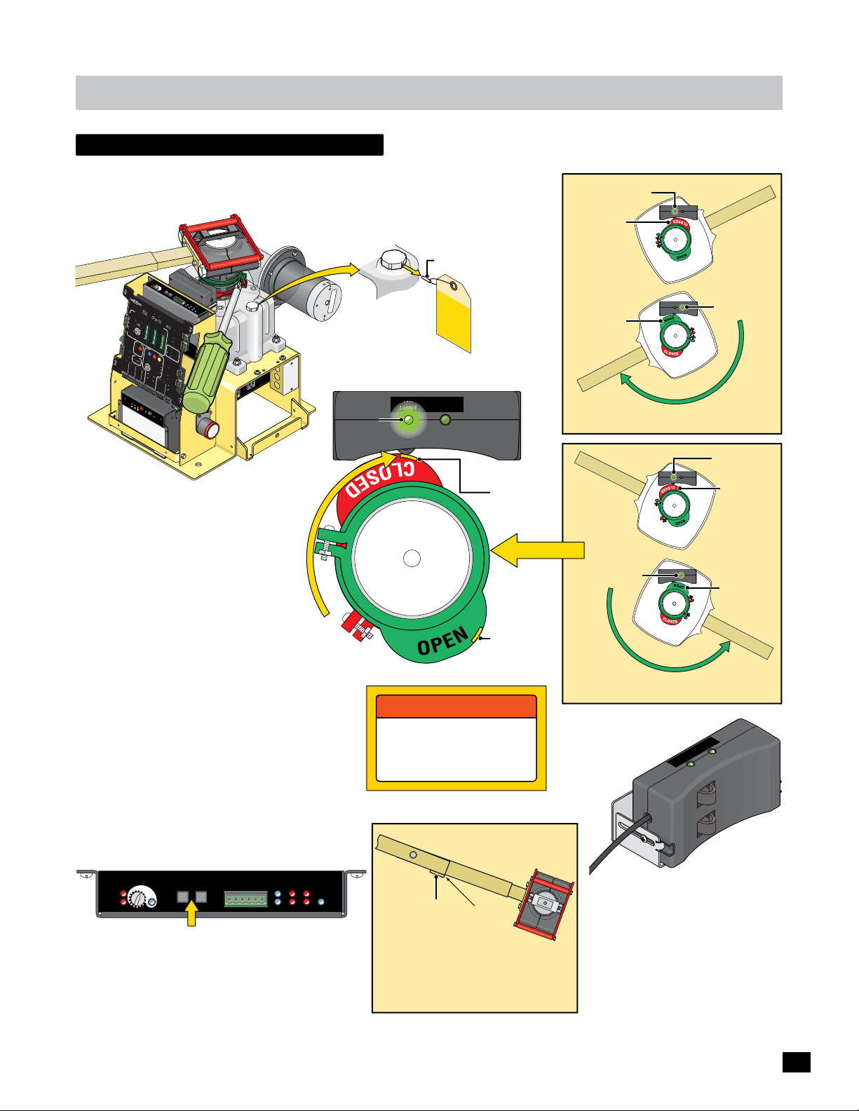
Adjustments
CAUTION
open and close limits
The limit tabs need to be set BEFORE the gate can be cycled or DAMAGE could occur.
IMPORTANT: Manually Release arm and move the
gate to the desired OPEN and CLOSED positions to
adjust the limit tabs. Make sure power is ON.
Breather Pin
Ov
Mo
er
t
or
L
o
ad
E
Se
ER
R
n
D
s
i
D
t
i
v
i
t
y
5
1
2
4
1
3
3
1
4
1
1
5
6
J
O
M
LEFT
G
AX
L
ED
O
N
J
OG
R
I
G
H
T
T
L
MA
TRIX
1
MADE
i
n
US
A
AU
TO
MAT
ANTI
E
X
T
I
T
AI
L
G
AT
O
CE
NT
E
R
SA
FE
T
Y
M
IN
O
M
F
A
F
CL
X
O
S
E
T
ID
IM
E
PLU
R
G
P
A
R
TI
AL
O
P
EN
12
V
DC
G
ND
POS
I
R
T
E
IO
24
CO
VD
N
R
C
D
GN
ER
D
O
B
D
B
P
LA
O
RT
C
K
B
O
X
IG.
T
RADIO S
DEP
RADIO GND
OPEN
D
RD
X
FIRE
E
/
GN
K
MA
GND
STRI
EYPAD
GND
K
B
a
t
te
ry
Vo
E
l
t
a
g
e
2
F1/
ADJUST LIMITS:
Manually Release Arm
1. Move gate to OPEN position.
2. Loosen open limit tab screw.
3. Rotate open limit tab until open
LED lights.
4. TIGHTEN open limit tab screw.
T
og
R
J
D
og
1
J
GN
e
2
e
o
Edg
Edg
l
l
Phot
e
C
M
A
O
T
N
RI
L
X
B
A
BACK-
T
T
U
P
L
L
E
E
A
A
V
CLOS
V
E
O
P
E
N
I
C
OP
E
E
XIT
F
FON
PWR 24V -
M
AX
G
MI
N
M
A
X
R
D
PR
GN
PHOTOCELL
GND
(+
O
N/
O
FF
Ba
tt
Re
e
r
y
p
B
a
t
t
I
NE
E
RY
MO
D
E
E
E
D
O
P
E
N
1
T
I
ME
EN/CL
D
R
A
IX
RS-485 (-) -
GND -
O
PE
A
T
E
SP
M
ON
I
MA
R
G
Y
A
T
E
)
D
GN
)
(-
la
c
e
e
r
TEST
y
Ba
E
L
d
i
m
g
1
e
it
S
W
Mot
U
2
L
E
n
MC
t
or
E
ra
d
p
g
e
C
-2
o
P
PO
h
nt
o
t
0
o
r
Ce
oll
0
W
ll
PR
IM
AR
G
Y
A
T
E
OP
E
N
L
E
F
T
OPE
RI
N
GHT
O
S
E
BO
C
O
MATR
N
TR
RS-485 (+) -
CEN
O
T
E
R
SAFETY
M
M
OT
OR MO
T
IO
N
N
ST
O
P
CL
R
E
VE
O
E
SE
RS
ED
E
S
E
NS
I
MO
T
I
VI
T
T
O
Y
R OV
E
RL
NO
OA
L
D
I
MI
CL
T
A
S
MP
W
I
T
S
C
L
H
I
P
/
P
I
NG
L
IM
SW
IT
IT
ON-
C
H
L
INE
OT
OR
-LINE
SEC
G
A
T
E
)
D
(+
GN
)
E
(-
OPEN
STOP
CLOS
MAX
Ba
t
BC-
te
r
y
M
7
odu
l
e
t
t
Ba
e
r
y
t
t
e
r
y
IN
Er
r
o
r
e
ER
r
M
AG
L
O
D
CK
ELA
O
F
F
Y
1
.
5
S
e
c
2
S
ec
M
LS
AG
L
O
CK
CO
M
N
C
G
A
T
R
E
A
TA
L
A
M
T
H
PER
am
C
IT
p
SW
er
MIT
I
L
K
N
O
AC
P
Y
R
E
CO
T
T
BA
M
S
T
U
G
P
T
N
N
I
am
R
D
O
per
OT
M
IN
n
I
Power
PH
UL
O
T
O
CE
L
R
L
E
TO
NT
R
E
A
MO
D
P
G
E
1
E
D
G
E
2
ID
PL
U
G
ER
R
O
R
U
L
AL
AR
ALAR
M
1
2
V
M
R
E
R
T
ESE
T
G
N
G
D
A
T
E
ST
A
T
U
S
O
PE
N
CO
M
CLOSE
LE
BA
B
T
T
E
RY
IN
U
DISA
SE
M
TE
PO
CO
WER
GA
24V
GND
n
o
i
ct
te
ro
p
e
d
th
e
u
n
i
t
with
n
y
.
l
e
co
n
s
r
o
u
o
f
f
ce
F
s
:
o
s
la
a
g
p
p
le
NG
I
re
e
tin
re
t
,
n
n
r
ra
le
re
u
d
fi
b
co
ARN
o
n
si
n
st
W
p
a
u
:
in
e
f
s
a
n
ctio
yp
e
g
t
te
u
a
r u
o
q
e
r
i
MENT
me
st
p
lis
i
t
ri
SE
sa
la
u
S
té
I
,
c
re
T
e
i
tt
ra
d
ER
n
ca
me
V
t
ce
ro
A
e
in
’
e
d
mp
yp
s
t
co
e
s
u
sq
me
ri
s.
mê
e
l
e
a
d
n
mi
o
n
p
m
A
7
FUSE
max
A
On
3
WER
VAC
PO
5
11
f
Of
s
t
h
g
i
l
D
E
L
l
i
t
n
u
b
a
T
t
i
m
i
L
e
t
a
t
o
R
CLOSED
LIMIT
LED
lights
Arm in CLOSED
position
Operator
Opens RIGHT
CAUTI
REMOVE
BEFORE
OPERA
OPEN
LIMIT
ON
TION
IMPORTANT:
Remove breather
pin from gear
reducer BEFORE
cycling operator.
CLOSED Limit
switch contact
point.
EXAMPLE:
5. Move gate to CLOSED position.
6. Loosen closed limit tab screw.
7. Rotate closed limit tab until closed
Limit
Tab Screw
OPEN Limit
switch contact
point.
LED lights.
8. TIGHTEN closed limit tab screw.
CAUTION
IMPORTANT: Manually Secure Arm (see page 36)
Cycle the gate OPEN and CLOSED after the limit
tabs have been set AND the arm is SECURE.
Operator will cycle slowly to LEARN the open and
closed gate positions. After the operator learns
the gate positions, it will cycle at the GATE SPEED
selected for normal operation.
“Fine Tune” Limits Adjustment
Motor
OverLoad
ERD
Sensitivity
12
13
ERD
14
5
4
3
16
15
MAX
LED ON
JOG
LEFT
JOG
RIGHT
GND
MATRIX
Cell
Photo
Jog LT
Edge 1
ON-LINE
Edge 2
Jog RT
Limit SW
Push and HOLD the JOG LEFT or JOG RIGHT buttons
accordingly on the MAX MC-200 motor controller to
move the gate (release the button to stop gate). This
allows gate to be moved back and fourth without leaving
the operator to “fine tune” the open and close gate
positions if desired.
WARNING: Avoid the moving arm while “Fine Tune” adjusting.
Edge
1
2
Edge
MC-200
Motor Controller
UL Entrap
POWER
PhotoCell
Make sure OPEN/CLOSE
limit rings are tightened
after adjustment or
slippage could occur.
Arm in Closed Position
Short Arm
Positive Stop
on Long Arm
1/4” gap
IMPORTANT: DO NOT allow
positive stop on long arm to
touch short arm in closed
position. Leave about a 1/4” gap.
Approximate OPEN and CLOSED
limit tab positions.
CLOSED LED
CLOSED Tab
Arm Closed Position
Activated
Position
OPEN LED
OPEN Tab
Activated
Position
Arm Open Position
A
r
m
O
p
e
n
o
i
t
c
e
r
i
D
n
g
i
n
Open LEFT
Arm Closed Position
OPEN LED
A
r
m
O
p
e
n
i
D
g
i
n
CLOSED LED
CLOSED Tab
Activated
Position
OPEN Tab
Activated
Position
Arm Open Position
n
o
i
t
c
e
r
Open RIGHT
LED Indicators
OPEN
IMIT
L
D
E
IMIT
CLOS
L
Open Limit Switch
Closed Limit Switch
Limit
Switch Box
IMPORTANT: LEDs MUST light up
when gate reaches OPEN and
CLOSE positions or operator WILL
NOT learn gate positions. If gate
positions are not learned, gate
cycling speed will remain slow
during normal operation.
35
Page 38
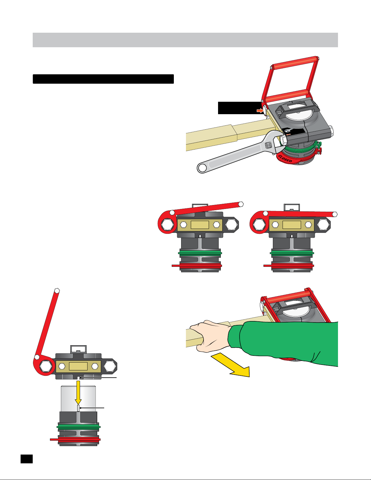
Adjustments
release handle clamp
Adjustment:
Tighten the Adjustment bolt until desired result is achieved.
The release handle clamp has been factory adjusted and
SHOULD NOT need any adjustment.
IMPORTANT: The red handle MUST BE FIRMLY secure in the
HORIZONTAL position.
IMPORTANT: The arm MUST NOT slip
when the gate is cycling or the gate OPEN
and CLOSE limit positions will NOT be
LEARNED. Gate speed will remain slow if
gate positions are NOT learned.
NO
factory set bolt
DO NOT adjust
Release Handle Clamp MUST be
HORIZONTAL when FIRMLY secured.
Adjustment
Bolt
lt
bo
t
ip
r
us
j
g
ad
irm
f
for
Release Handle Clamp
36
Re-Attach to Operator:
Limit pin MUST fit into slot in bottom of
release handle clamp directly under the
arm when reattaching arm to operator.
Arm
Slot
Limit Pin
Limit Tabs
After Release Handle Clamp is in the SECURE HORIZONTAL
position:
Pull the arm. NO slippage should occur.
If it does, readjust.
NOTE: When limit tabs are already set and the release handle is put
back in the secure position but the gate is NOT in the full open or close
position, the operator will automatically re-align the gate’s open and
close tabs. No readjustment is necessary.
Page 39
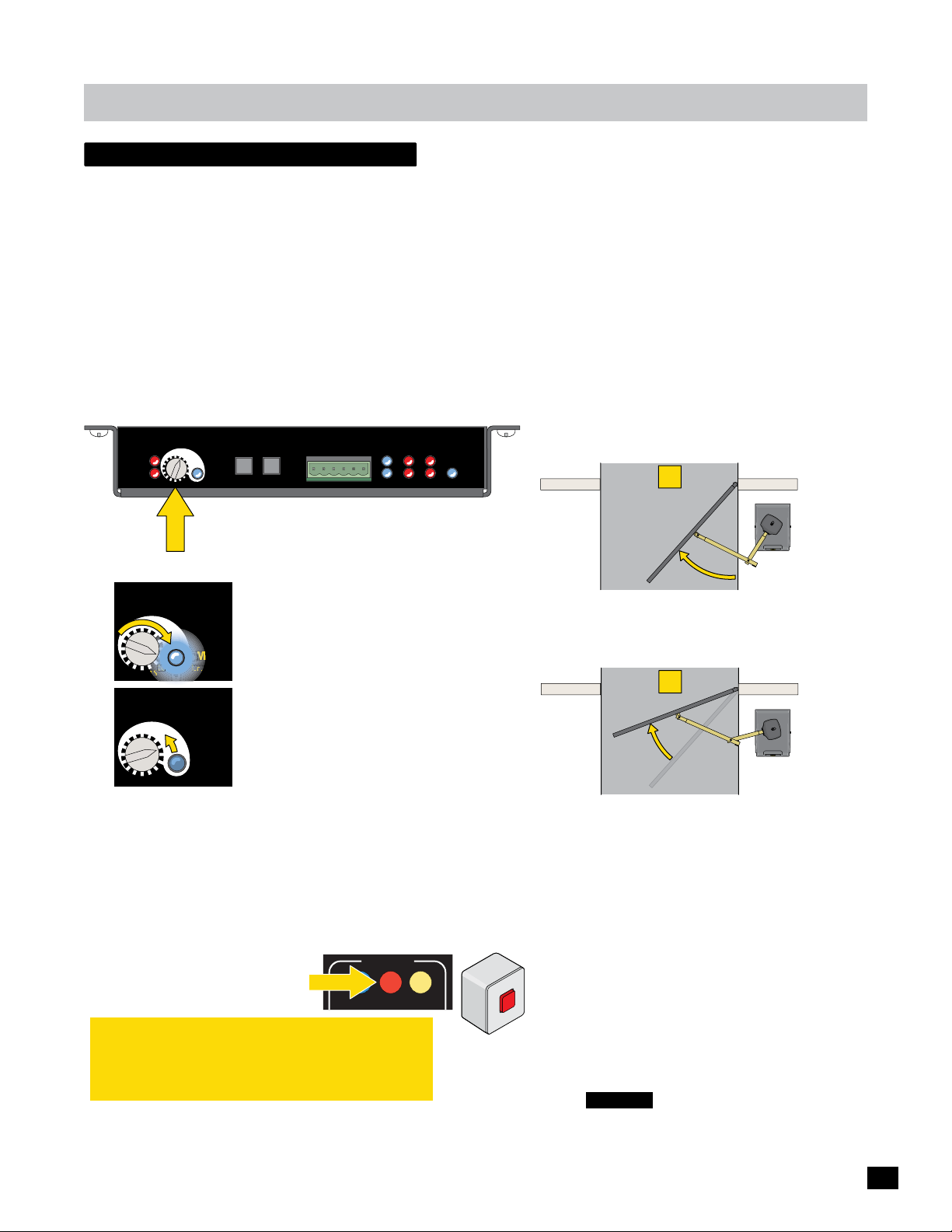
Adjustments
STOP Gate
Half-way
CLOSE Gate
E
6
reverse sensor (erd)
This operator is equipped with an ERD Sensor - Electronic Reversing Device (Type A) that functions as entrapment protection
according to UL 325 standards. The gate will reverse direction after encountering an obstruction in either the OPEN or
CLOSE gate cycle.
When the gate encounters an obstruction during the CLOSE cycle, it will reverse to the open position and PAUSE the gate. An
input command (press remote button or exit loop) is needed BEFORE the gate will reset and close again.
When the gate encounters an obstruction during the OPEN cycle, it will reverse approximately 6 inches and PAUSE the gate. An
input command (press remote button or exit loop) is needed BEFORE the gate will reset and open again.
For the ERD Sensitivity to function correctly:
• THE RELEASE HANDLE CLAMP MUST NOT SLIP when the gate encounters an obstruction.
• Limit switches must be learned BEFORE adjusting the ERD Sensitivity.
Motor
OverLoad
ERD
Sensitivity
12
13
ERD
14
JOG
JOG
LEFT
5
4
3
MAX
16
LED ON
15
RIGHT
GND
MATRIX
Cell
Jog LT
Photo
Edge 1
ON-LINE
Edge 2
Jog RT
Limit SW
1
2
Edge
Edge
UL Entrap
PhotoCell
MC-200
Motor Controller
POWER
16 sensitivity setting positions.
NO mechanical hard stop for knob.
Adjusting ERD Sensitivity
ERD
Sensitivity
12
13
14
ERD
Sensitivity
12
13
14
5
4
3
16
LED ON
15
5
4
3
16
LED ON
15
A. Turn knob until blue LED lights up.
Max sensitivity reached, Position 1.
“1” - Maximum sensitivity setting.
Too sensitive for most gates. (LED lights)
MAX
“16” - Minimum sensitivity setting.
Not sensitive enough for most gates. (LED is off)
B. Turn knob counter-clockwise to reduce
sensitivity during ERD testing as needed.
(LED remains OFF for all but position 1)
MAX
Testing ERD Sensitivity
Allow the gate to strike an immobile object while OPENING and
CLOSING. The gate MUST reverse direction after striking the object.
Increase or decrease the ERD Sensitivity as needed. Repeat this
process until the correct sensitivity is achieved. If alarm sounds
while preforming this procedure,
press STOP BUTTON on Matrix 1
Matrix 1
MOTOR MOTION
or externally mounted Alarm
Reset button to shut-off alarm.
OPEN STOP CLOSE
IMPORTANT: When satisfied with ERD adjustment,
cycle the gate 3 or 4 times to make sure that the ERD
sensor does not falsely trigger during normal gate
operation. Readjust if this happens.
External Alarm
Reset Button
SS
PRE
to RESE
TIP: While Adjusting ERD. . . . .
1
STOP Gate
Half-way
Position gate half-way open and STOP gate.
This gate position will put the most amount of
resistance on the ERD sensor when gate cycles.
2
CLOSE Gate
CLOSE gate. If ERD sensor triggers, reduce
sensitivity. If sensor does NOT trigger,
sensitivity is set correctly.
“Min” ERD Position 16 Setting
When solid gates are installed in:
• Unusually high wind areas
T
• Uphill opening gate
• Heavy gate
ERD sensor can be set to Min (position 16)
to keep the gate cycling normally in such
extreme conditions.
CAUTION: Minimum sensitivity setting
(position 16) results in gate exerting
MAXIMUM force before reversing direction.
37
Page 40

maintenance
qualified gate operator technician
Maintenance and repair of the gate operator must be preformed by a qualified professional gate operator technician.
The following services need to be periodically performed:
• Check and adjust the gate operator’s force, speed, and sensitivity.
• Make sure all power (AC/DC) connections are corrosion free.
• Check all batteries for proper voltage.
• Check the incoming line voltage and confirm it is within 10% of its rating (115 or 230 volts).
• Verify battery backup functionality by turning off the power source (115 VAC and 230 VAC). Restore power after testing.
• Cycle gate system and lubricate with heavy-duty, high-performance lubricant where needed.
• Test all contact and non-contact sensors, in-ground vehicle loop detectors, keypad, telephone entry system or any other access
control devices that are used to control the gate operator.
• Test the manual release feature.
MAKE SURE END USER/HOME OWNER KNOWS HOW TO PROPERLY REMOVE GATE OPERATOR FROM SERVICE AND WHO TO
CONTACT FOR PROFESSIONAL ASSISTANCE.
Date Installed:
Installer/Company Name:
Operator
Phone Number:
end user / homeowner
Any repairs and modifications must be preformed by a qualified professional gate operator technician. If the gate or gate
operator ever malfunctions, end user/home owner needs to immediately remove the gate operator from service (manually
position gate (see manual release) in a desired prolonged position and turn ALL power OFF to the gate operator). End
user/home owner must call a qualified professional gate operator technician for any repairs and modifications.
The gate operator is virtually maintenance free to an end user/home owner, minimal maintenance is recommended to ensure
reliable operation.
End user/home owner:
• Scheduled maintenance should be performed approximately every six months by a qualified professional gate operator
technician, or when unusual noises are heard from the gate hinges and/or gate operator arm.
• DO NOT remove the operator cover to perform any normal maintenance.
• Lubricate gate hinges and gate operator arm periodically with heavy-duty, high-performance lubricant and clean up all excess
lubricant.
• Make sure there are no vehicles or pedestrians in the path of the gate while performing maintenance.
• Make sure the person performing maintenance is the only person in control of all control devices in order to avoid possible
involuntary activation of the gate operator. Gate operator MUST be removed from service while maintenance is performed.
• Keep any water from landscape watering hoses or sprinkler systems away from the gate and gate operator area.
• Keep the area around the gate and gate operator as clean as possible.
• Keep any debris away from the gate’s swinging path.
• Test periodically (use caution) all safety sensors, in-ground vehicle loop detectors, keypad, telephone entry system or any
other access control devices that are used to control the gate operator. Make sure everything is working properly.
• Solar panel must be cleaned periodically if solar power is being used.
Serial Number:
38
Page 41
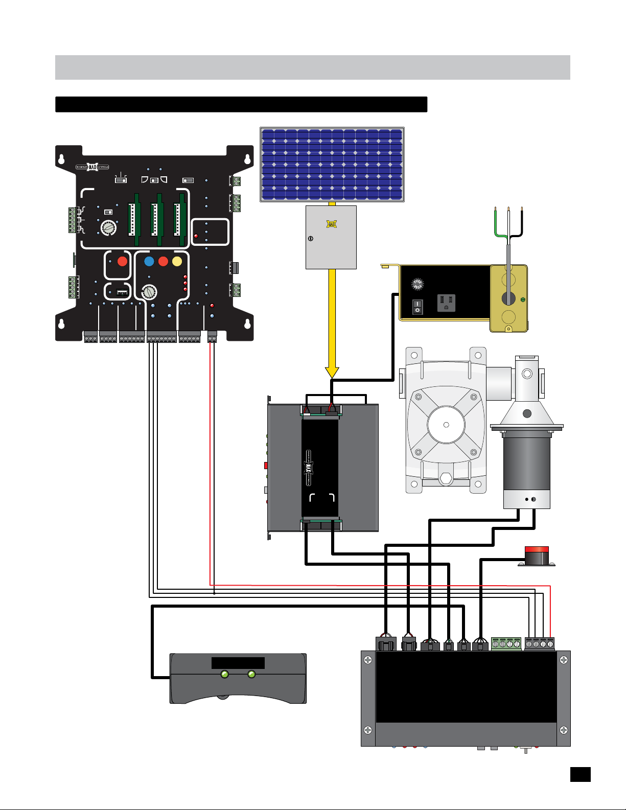
Maintenance
megatron primary wiring schematic
Matrix 1
MATRIX 1
ID
PLUG
12VDC
GND
24VDC
GND
BATTERY
BACK-UP MODE
LEAVE
MADE in USA
OPEN
AUTOMATIC OPEN/CLOSE CONTROLS
ANTI
TAILGATE
EXIT
OFFON
CENTER
SAFETY
MIN
MAX
OFF
CLOSE TIMER
PARTIAL
OPEN
POSITION
RECORDER
OBD PORT
BLACK BOX
FIRE DEPT
GND
MAX OPEN
GND
RADIO SIG.
RADIO GND
PRIMARY
STRIKE
OPEN
1 TIME
GND
KEYPAD / RDR
GND
MAX
GATE SPEED
MIN
MAX
PHOTOCELL
OPEN
LEFT
OPEN
PRIMARY
GND
GATE
OPEN
RIGHT
MOTOR MOTION
STOP CLOSE
REVERSE SENSITIVITY
LIMIT
SWITCH
ON-LINE
MOTOR
ON-LINE
GATE
(+)
GND
(-)
SAFETYCENTEREXIT
MOTOR OVERLOAD
NO LIMIT SWITCH /
CLAMP SLIPPING
SEC
GATE
(+)
GND
(-)
MAGLOCK
OFF
OPEN
DELAY
MAG
2Sec1.5Sec
LOCK
COM
NC
Tamper NO
GATE
COM
TAMPER
GND
Tamper IN
PHOTOCELL
UL
EDGE 1
ENTRAP
EDGE 2
ID PLUG
ERROR
UL ALARM 12V
ALARM RET
RESET
GND
OPEN
GATE
COM
STATUS
CLOSE
BATTERY
IN USE
POWER
24V
GND
STOP
CLOSE
COM
GATE DISABLE
LEAVE
CLOSED
Solar Panel 24V
Solar
Panel
Electronics
Box
to POWER/SOLAR IN
“Optional”
MAX Solar
Power Kit
7 Amp
WARNING: For continued protection
against fire, replace only with the
same type and rating of fuse.
AVERTISSEMENT: pour ne pas
compromettre la protection contre les
risques d’incendie, utiliser un fusible
de mêmes type et caractéristiques
nominales.
FUSE
On
POWER
Off
115VAC 3A max
Input AC Power
115VAC or 230VAC
Green
White
Black
MAX
Megatron
Junction Box
Toroid
Box
CLOSED
OPEN
LIMIT
LIMIT
Limit Switch Box
IN
Pack
BATTERY
Battery
POWER/SOLAR
IN
CONTROLLER
TO MOTOR
IN
www.Max.US.com
POWER
Battery Module
MAX BC-7
MOTOR
3-Pin
Power In
2-Pin
6-Pin
3-Pin
LIMIT
BATTERY
MOTOR
INPUTS
PACK
SWITCH
MAX MC-200
Motor Controller
4-Pin
ALARM
5-Pin
Motor
GND -
not used -
not used -
Alarm
PWR 12V -
RS-485 (-) -
RS-485 (+) -
MATRIX 1
GND -
PWR 24V -
39
Page 42
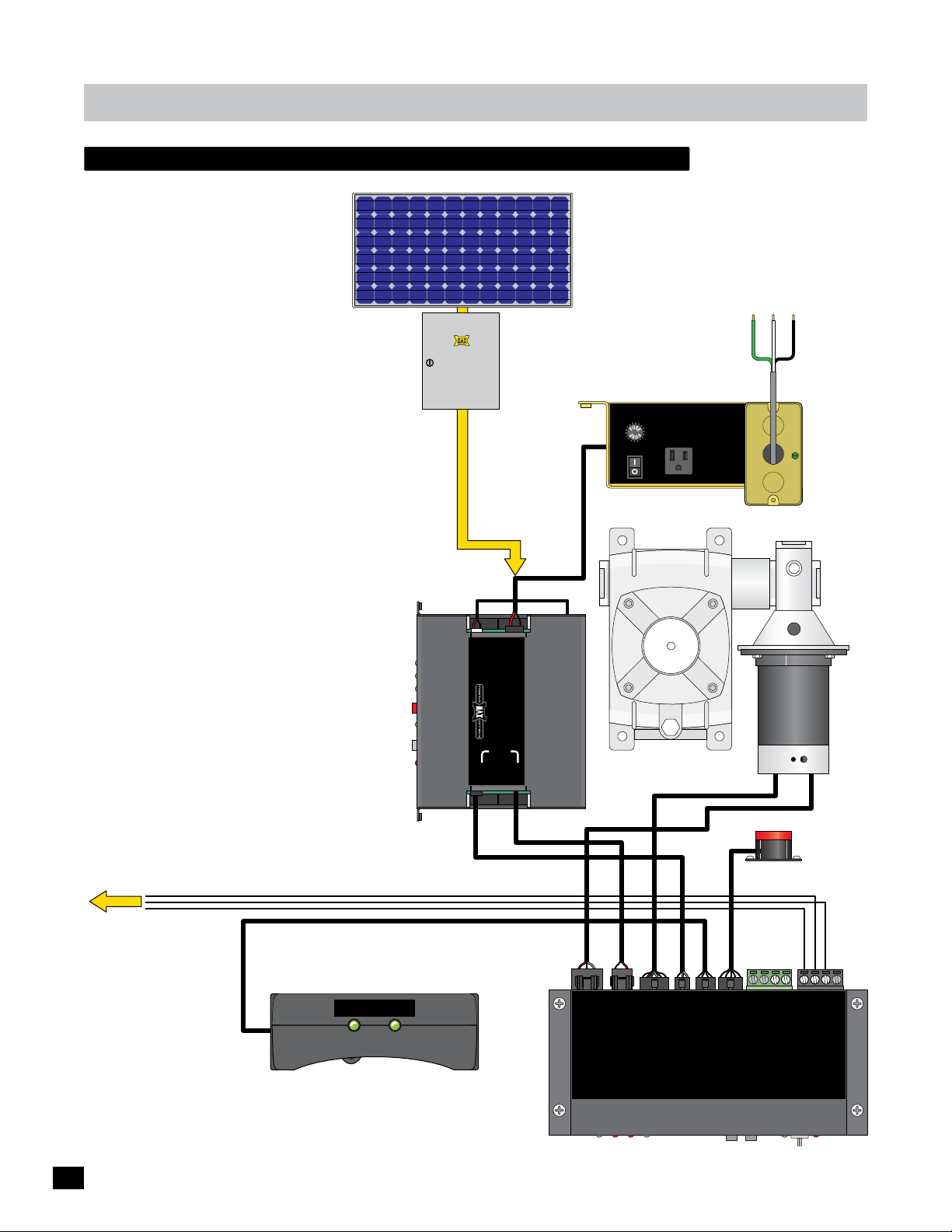
Maintenance
megatron secondary wiring schematic
Solar Panel 24V
“Optional”
Solar
Panel
Electronics
Box
MAX Solar
Power Kit
to POWER/SOLAR IN
WARNING: For continued protection
against fire, replace only with the
same type and rating of fuse.
AVERTISSEMENT: pour ne pas
compromettre la protection contre les
risques d’incendie, utiliser un fusible
de mêmes type et caractéristiques
nominales.
7 Amp
FUSE
On
POWER
Off
115VAC 3A max
Input AC Power
115VAC or 230VAC
Green
White
Black
MAX
Megatron
Junction Box
Toroid
Box
To “SEC GATE” input
on Matrix 1
CLOSED
OPEN
LIMIT
LIMIT
Limit Switch Box
IN
Pack
BATTERY
Battery
POWER/SOLAR
IN
CONTROLLER
TO MOTOR
IN
www.Max.US.com
POWER
Battery Module
MAX BC-7
MOTOR
3-Pin
Power In
2-Pin
6-Pin
3-Pin
LIMIT
BATTERY
MOTOR
INPUTS
PACK
SWITCH
MAX MC-200
Motor Controller
4-Pin
ALARM
5-Pin
Motor
Alarm
GND -
not used -
not used -
PWR 12V -
RS-485 (-) -
RS-485 (+) -
MATRIX 1
GND -
PWR 24V -
40
Page 43
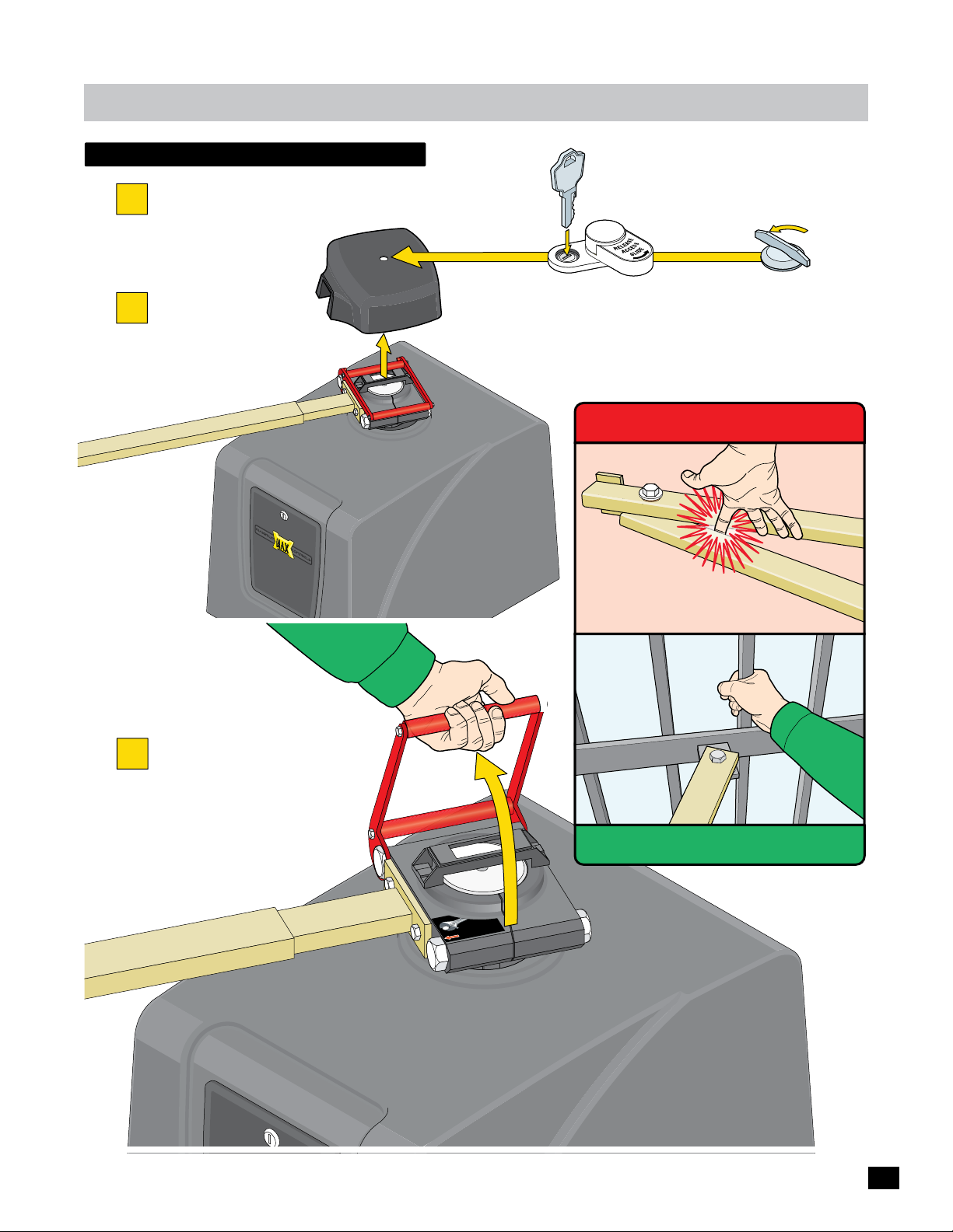
maintenance
WARNING
manual gate release
Make sure ALL power is OFF to operator.
1
Hood
Unlock or unlatch
2
hood and remove it.
Removable Key
Factory Installed Lock
OR
WARNING
Pinch Point
NEVER grasp the
arm to move gate!
Optional Non-Lockable Latch
Arm
Pull red handle up
3
and move gate.
DO NOT Lift Arm
OFF of Operator
Arm
djus
a
for firm grip
ALWAYS grasp gate to move it.
bolt
t
41
Page 44
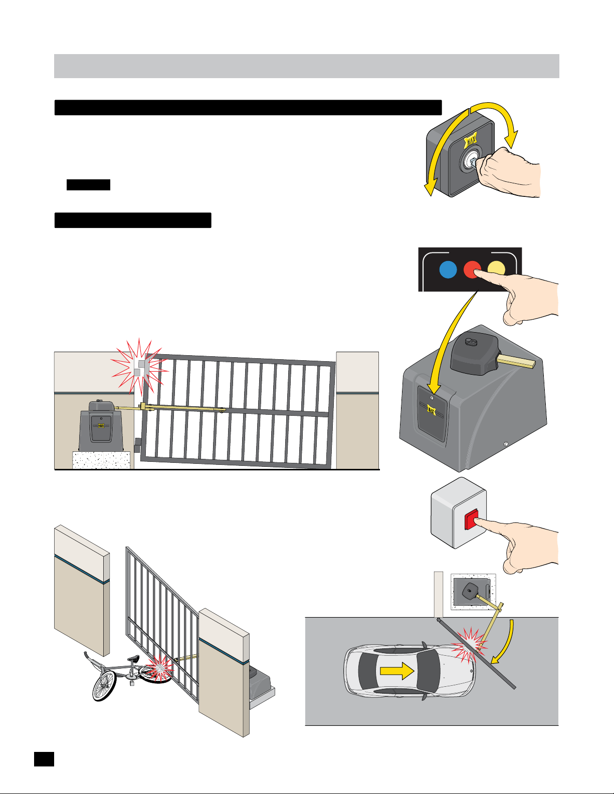
maintenance
electronic gate open / close - Optional
The OPTIONAL external key switch device (sold separately) can open or close the
gate electronically if the switch has been wired to the MC-200 motor controller.
Insert key on control box, turn and HOLD (in either direction) to MOVE gate.
CAUTION: Keep pedestrians and vehicles clear of the gate while it is moving.
audible alarm
If the Alarm Sounds During Normal Gate Operation: When the gate encounters
TWO consecutive obstructions before completing a gate cycle, the alarm will sound and
the gate will PAUSE in the position where the second obstruction occurred. CHECK THE
GATE AREA FOR ANY PROBLEMS BEFORE pressing the STOP button on the Matrix 1
or the externally mounted Alarm Reset button to shut off the alarm and reset the gate.
NOTE: Alarm will automatically shut-off after five minutes but will not allow gate to
operate until the STOP button is pressed.
Some reasons why the alarm sounds:
CLOSE
OPEN
Alarm Shut-OFF
MOTOR MOTION
OPEN STOP CLOSE
Matrix 1
STOP Button
• HINGES are TOO TIGHT or BROKEN, gate CANNOT move freely.
• Gate is STUCK or BENT in an awkward position.
A FOREIGN OBJECT is on the gate frame while the gate is moving.
•
The gate is TOO HEAVY.
•
• The gate operator tries to close the
gate but gate gets CAUGHT on an
object and cannot move.
42
Externally Mounted
Alarm Reset Button
shuts-off alarm.
PRESS
to RESET
OUTSIDE Property
Moving Vehicle is Entering
INSIDE Property
Gate is Closing
• The moving gate gets PUSHED by a moving VEHICLE.
Page 45
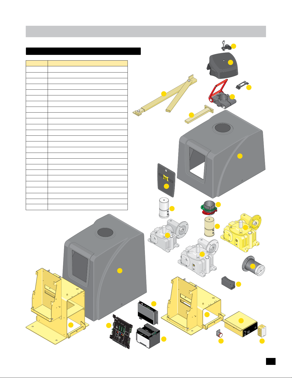
maintenance
replacement parts list
1
Item
1
2
3
4
5
6
7
8
9
10
11
12
13
14
15
16
17
18
19
20
21
22
23
24
25
Description
Camlock Assembly with cover and key
Plastic Hood
Hood Latch Bracket
Output Clamp Assembly
Swing arm T-Bar
Operator cover - MAX Megatron 1400/2200/FAST
Door for cover
Output collar and rings
Output Shaft for MAX Megatron 1400 & HP
Output Shaft for MAX Megatron 2200/FAST
Double Gear Box MAX Megatron 2200 (Silver)
Double Gear Box MAX Megatron FAST (Yellow)
Double Gear Box MAX Megatron 1400 & HP (Gray)
DC Brushless Motor
Swing Arm Assembly
Limit Switch Box
Chassis MAX Megatron 1400/2200/FAST
MAX Megatron Toroid Box Power Supply
Alarm
MC-200 Motor Controller (Megatron)
Matrix 1 Control Board Assembly
BC-7 Battery Module (7Ahr)
Single Gang Box
Operator cover - MAX Megatron 1400HP
Chassis MAX Megatron 1400HP
2
3
15
4
5
6
7
8
9
10
12
13
11
14
24
16
Ove
M
o
t
o
r
L
r
o
a
d
ER
S
ER
ens
D
i
D
t
i
vit
y
5
1
2
4
13
3
14
15
16
J
OG
M
L
EF
A
LE
X
D
20
T
O
N
J
O
R
G
I
G
HT
T
L
T
g
o
R
J
D
g
o
1
J
GN
e
2
g
e
o
g
Ed
t
o
Ed
l
l
Ph
e
C
MA
O
T
N-
R
IX
L
I
N
E
E
L
d
i
m
g
1
e
i
t
S
W
M
U
2
L
o
E
n
t
MC
t
o
E
r
a
d
r
p
g
e
C
-
o
P
2
P
h
n
o
t
t
0
O
o
r
C
o
0
WE
e
l
l
l
l
e
r
RD
X
RI
PWR 24V -
M
A
T
RI
X 1
M
A
B
DE
A
B
T
i
A
n
T
US
C
E
K
RY
A
U
P
M
L
O
L
E
EAV
D
A
VE
C
E
L
E
OP
OS
E
E
N
D
P
R
I
M
OP
A
EN
RY
G
A
1
A
T
U
I
T
M
E
E
TO
M
O
P
E
ATI
N
L
E
F
T
C
O
A
P
O
N
E
E
XIT
T
R
T
N
P
A
I
I
G
I
E
H
L
T
GA
N
/
T
M
C
E
L
ON
O
S
E
E
OF
OF
X
F
C
I
F
C
T
E
NTER
O
N
T
R
O
EN
L
T
25
21
S
ER
S
A
F
E
T
Y
S
A
F
E
T
YC
M
IN
O
M
F
A
F
C
X
LO
S
E
T
I
I
D
M
E
P
R
L
U
G
P
A
RT
IA
O
L
P
E
N
1
2V
DC
GN
D
M
OT
P
OR M
O
S
I
RE
T
OT
I
2
O
CO
4V
N
I
E
DC
ON
NT
R
D
GN
E
R
D
O
B
D
B
O
P
L
O
P
A
R
E
C
T
N
K
M
B
O
A
X
X
S
T
O
P
G
A
T
E
C
RE
S
L
M
P
V
O
I
E
N
E
S
RS
E
.
E
D
E
S
M
E
A
NS
X
I
M
T
SIG
I
O
V
T
I
T
ND
OR
Y
O
O
G
I
V
T
E
RL
NO
P
OA
O
L
I
D
AD
I
E
N
M
C
I
T
L
E
R
D
AM
SW
AD
P
P
I
R
T
SL
C
H
R
O
I
D
P
/
P
I
IRE
NG
R
ND
F
L
I
G
M
L
G
A
S
I
T
T
W
IKE
L
D /
E
ND
MAX
I
S
T
O
CH
T
N-
A
A
G
L
T
CE
I
TR
P
U
N
E
S
ND
S
O
M
T
EY
G
O
T
ND
K
O
O
P
N-
R
R
G
I
L
HO
M
I
N
A
R
E
ND
P
GA
Y
T
E
G
D
+)
S
(
E
C
GN
)
GA
-
T
(
E
+)
(
N
GND
)
ABLE
-
E
(
S
PE
OP
O
T
OS
S
L
E DI
C
OM
T
A
C
G
GND -
A
G
L
O
DE
CK
L
A
Y
1
.
5
Se
c
2
S
e
c
M
AG
L
O
C
K
C
O
M
N
C
G
A
T
E
TA
M
T
P
a
m
ER
p
e
r
N
O
CO
M
G
T
N
a
D
m
p
e
r
I
N
P
H
U
O
L
T
O
C
E
L
L
R
E
AP
D
G
E
1
E
D
G
E
2
I
D
P
L
U
G
E
RR
O
R
U
L
A
L
A
R
A
M
L
A
12
RM
V
R
E
R
T
E
S
E
T
G
N
D
OP
E
N
C
O
M
C
L
O
S
E
BA
T
T
E
RY
I
N
U
S
E
P
O
W
E
R
V
4
ND
2
G
R
A
BO
T
MA
RS-485 (-) -
RS-485 (+) -
M
R
A
L
A
H
C
T
I
W
S
T
I
M
I
L
K
C
A
P
Y
R
E
T
T
A
B
S
T
U
P
N
I
R
O
T
O
M
n
I
r
Powe
OR
OT
M
P
O
WE
R/
S
O
I
N
L
AR
BA
T
w
TER
w
I
N
w
Y
.
M
a
x.
U
S.
co
m
CO
TO
NT
M
P
O
O
R
T
WE
O
O
L
R
I
L
R
C
N
E
M
R
B
a
t
t
e
r
y
V
E
o
l
t
a
g
1
e
/
2
F
O
N
/
O
F
B
F
a
t
R
t
e
e
r
y
p
B
a
t
t
N
I
o
T
R
Bat
t
WE
e
P
r
a
O
y
c
P
k
M
AX
B
a
BC-7
t
t
e
r
y
la
MC
M
c
e
o
o
ack
d
u
T
e
l
e
r
T
y
E
S
T
ery P
B
t
a
t
t
t
B
e
a
r
y
t
Ba
t
e
r
y
I
N
E
r
r
o
r
22
17
18
n
io
t
c
e
t
o
r
p
e
h
d
t
e
h
u
t
n
i
t
wi
n
.
o
ly
e
c
n
s
r
o
u
o
f
e
F
f
c
s
:
o
s
la
a
le
g
p
p
e
NG
in
e
r
e
t
r
t
,
n
ra
n
e
e
r
l
o
ir
u
d
f
b
c
ARNI
i
o
n
t
s
n
p
a
s
W
u
o
f
:
n
i
i
e
t
s
a
p
n
c
NT
y
e
g
u
e
t
t
E
u
a
r
o
e
q
e
r
i
M
t
s
p
m
E
s
li
i
i
a
t
r
a
S
l
s
u
é
S
t
I
,
c
re
e
t
i
a
t
r
RT
d
e
a
n
c
m
e
VE
t
c
ro
A
e
p
in
’
e
d
m
p
o
s
ty
c
e
s
u
e
q
m
ris
ê
.
s
m
e
l
e
a
d
n
i
m
o
n
p
m
A
7
E
x
S
a
m
FU
n
A
O
R
3
E
C
W
A
V
PO
5
1
1
f
f
O
19
23
43
Page 46

max megatron warranty
Maximum Controls LLC (“Manufacture”) warrants the original purchaser of this
product, for the purpose to which this product is originally installed, that the product is
free from defect in materials and/or workmanship for a period of 8 years for the
Brushless DC Motor and cover, 5 years for everything else with the exception of the
batteries which are limited to a 1 year warranty. The performance of this product is
dependent on compliance to the instructions, maintenance, operation, and testing
clearly outlined in the user manual. Failure to comply completely with those instructions
will void this warranty in its entirety. This warranty does not cover damage to the
product caused by vandalism, water damage, direct hit lightning strike, or installation
errors. This warranty does not include any labor charges that might be needed to
troubleshoot, replace, or repair a problem.
If, during the limited warranty period, one of the components exhibits a defect in
material and/or workmanship, please call 949-699-0220 before dismantling the product.
Shipping instructions and an RMA (Return Material Authorization) Number will be
issued by the factory service center when contacted. Do not send any product in for
service without an RMA number. Shipping charges to and from the factory service
center for warranty repairs are the responsibility of the customer. Repair or replacement
of any warranty items is made at the sole discretion of the Manufacturer.
ALL IMPLIED WARRANTIES FOR THE PRODUCT, INCLUDING BUT NOT LIMITED TO
ANY WARRANTIES OF MERCHANTABILITY AND SUITABILITY FOR A PARTICULAR
PURPOSE, ARE LIMITED TO 8 YEARS FOR THE BRUSHLESS MOTOR DC AND COVER,
5 YEARS FOR EVERYTHING ELSE WITH THE EXCEPTION OF THE BATTERIES WHICH
ARE 1 YEAR. NO IMPLIED WARRANTIES WILL EXTEND BEYOND THE WARRANTIES
LISTED ABOVE. Some states do not allow limitations on how long an implied warranty
last so this limitation might not apply to you.
This Limited warranty does not cover any problems with or relating to, the gate, the gate
hardware, including but not limited to hinges, rollers, brackets, entry devices etc. Any
service call that determines the cause of a problem to be external to the product could
result in a fee. Under no circumstances shall the manufacture be liable for
consequential, incidental or special damages arising in connection with the use, or
inability to use, this product. Under no circumstances will the Manufacture’s liability for
breach of warranty, breach of contract, negligence or strict liability exceed the cost of
the product covered other liability in connection with the sale of this product.
44
Page 47
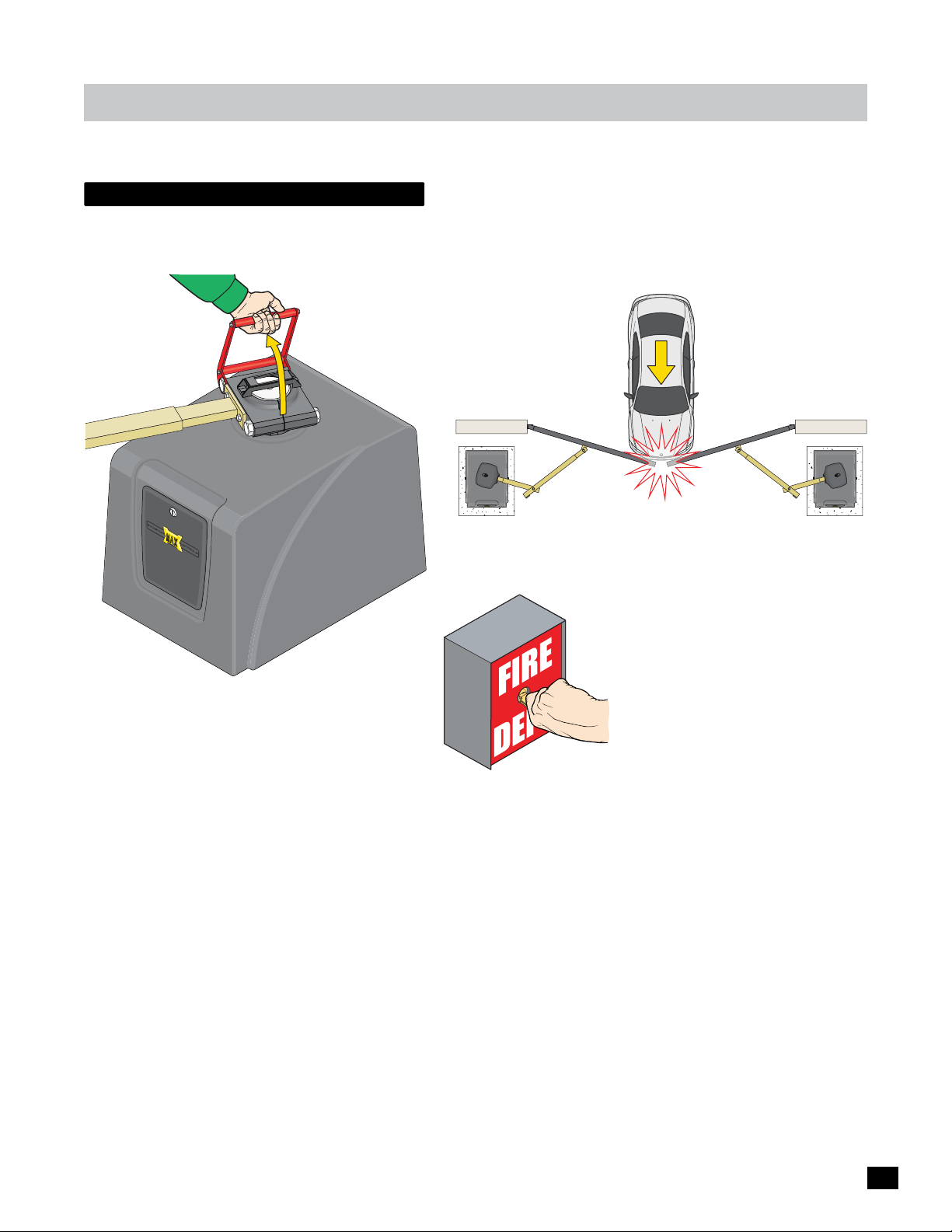
megatron options / unique Features
“Like NO other Gate Operator in the World”
gate tamper feature
The GATE TAMPER feature will activate the relay when a number of security circumstances occur, making illegal entry almost
impossible when the gate operator is connected to a existing building/home alarm system. The GATE TAMPER relay will activate
when:
The gate is PHYSICALLY moved from the
closed position with EXTREME force.
The red release handle clamp is lifted and
the gate is pushed open from the closed
position without authorization.
The FIRE switch is turned ONLY if
the GATE DISABLE has been turned ON.
45
Page 48
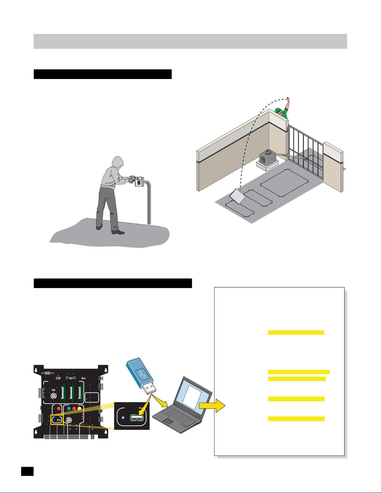
ALARM RET
megatron options / unique Features
“Like NO other Gate Operator in the World”
Gate disable feature
This unique GATE DISABLE feature is useful when the gated area needs to be secured from ALL but emergency and/or authorized vehicle entry. Some examples are:
• Residential home vacation period.
• During closed hours of a business.
The GATE DISABLE feature will allow the FIRE DEPT/MAX and
RADIO inputs to operate but nothing else. It helps with some
major security problems that can occur when no one is
available to monitor the property.
GATE DISABLE
prevents breaking into
a keypad box and
trying to trigger the
wires to get the gate
to open.
l
Meta
ate
Pl
EXIT LOOP
GATE DISABLE prevents trying to trigger
the exit loop to get the gate to open.
IMPORTANT: It is NOT recommended activating GATE DISABLE while persons are present inside the property.
event history download
This unique EVENT HISTORY feature has an On Board Diagnostics (OBD)
port to download a simple .txt file to troubleshoot gate operator errors
and to view normal transaction logs. This file will log intermittent
problems with the gate operator that can be difficult to solve. This file
can even be e-mailed to the factory from out in the field at the job site for
additional technical support if necessary.
The event history can store up to 1000 transactions.
USB Flash Drive
PRIMARY
BATTERY
MATRIX 1
MADE in USA
AUTOMATIC OPEN/CLOSE CONTROLS
EXIT
CENTER
SAFETY
CLOSE TIMER
ID
PLUG
12VDC
GND
24VDC
GND
RADIO SIG.
RADIO GND
TAILGATE
ANTI
MIN
FIRE DEPT
BACK-UP MODE
LEAVE
OPEN
OFFON
OFF
POSITION
RECORDER
BLACK BOX
GND
MAX
OBD PORT
MAX OPEN
GATE
LEAVE
CLOSED
OPEN
1 TIME
PARTIAL
OPEN
STRIKE
GND
GND
MAGLOCK
DELAY
OPEN
OPEN
LEFT
MOTOR MOTION
OPEN
MAX
GATE SPEED
MIN
MAX
PRIMARY
GATE
PHOTOCELL
GND
KEYPAD / RDR
GND
(+)
RIGHT
STOP CLOSE
REVERSE SENSITIVITY
LIMIT
SWITCH
ON-LINE
MOTOR
ON-LINE
GND
(-)
SAFETYCENTEREXIT
TOPLOSE
MOTOR OVERLOAD
NO LIMIT SWITCH /
CLAMP SLIPPING
SEC
GATE
(+)
MAG
OFF
2Sec1.5Sec
LOCK
COM
NC
Tamper NO
GATE
COM
TAMPER
GND
Tamper IN
PHOTOCELL
UL
EDGE 1
ENTRAP
EDGE 2
ID PLUG
ERROR
UL ALARM 12V
L ALARM 12V
ALARM RET
RESET
GND
OPEN
GATE
COM
STATUS
CLOSE
BATTERY
IN USE
POWER
24V
GND
OPEN
STOP
CLOSE
COM
GATE DISABLE
GND
(-)
OBD PORT
BLACK BOX
Event History Text Document Sample
Event type clarificaon:
INFO: informaonal message only
WARNING: unusual event but doesn't cause system malfuncon
ERROR: abnormal event, could cause system malfuncon
ENTRAP: entrapment detecon event
Event Report:
Fri 07/11/2014 10:59:41 INFO : Cycle Counter
Fri 07/11/2014 10:59:41 ENTRAP : SEC_MC: First ERD Detected
Fri 07/11/2014 10:59:37 INFO : Radio Input Deacvated
Fri 07/11/2014 10:59:36 INFO : Radio Input Acvated
Fri 07/11/2014 10:58:54 INFO : PRI_MC: Fully Open Posion Learned
Fri 07/11/2014 10:58:53 INFO : SEC_MC: Fully Open Posion Learned
Fri 07/11/2014 10:57:40 INFO : PRI_CIO: Communicaon Established
Fri 07/11/2014 10:57:38 ENTRAP : PRI_MC: Photo Cell Deacvated
Fri 07/11/2014 10:57:34 ENTRAP : PRI_MC: Photo Cell Acvated
Fri 07/11/2014 10:57:21 INFO : Radio Input Deacvated
Fri 07/11/2014 10:57:21 INFO : Radio Input Acvated
Fri 07/11/2014 10:56:46 WARNING: PRI_MC: Tamper Reported
Fri 07/11/2014 10:56:36 INFO : SEC_MC: Fully Open Posion Unknown
Fri 07/11/2014 10:56:36 INFO : PRI_MC: Fully Open Posion Unknown
Fri 07/11/2014 10:56:36 WARNING: PRI_MC: Tamper Reported
Fri 07/11/2014 10:56:33 ENTRAP : PRI_MC: Photo Cell Deacvated
Fri 07/11/2014 10:56:33 ENTRAP : PRI_MC: Photo Cell Acvated
Fri 07/11/2014 10:56:33 ENTRAP : PRI_MC: Photo Cell Deacvated
Fri 07/11/2014 10:56:33 ENTRAP : PRI_MC: Photo Cell Acvated
46
Page 49

474849
Page 50

Page 51

Page 52
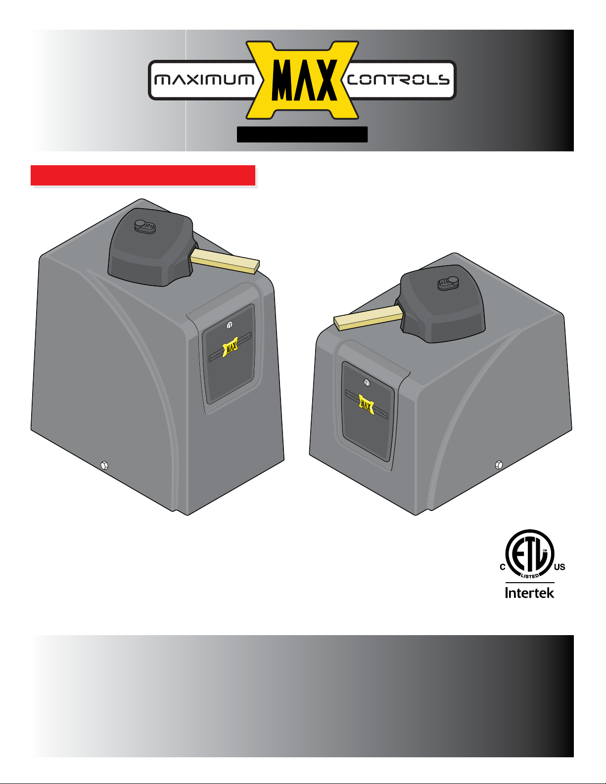
www.max.us.com
SAFETY SENSORS REQUIRED
1400HP
CONFORMS TO UL STD 325
UL CLASS - I, II, III, IV
CERTIFIED TO CAN/CSA STD
C22.2 NO. 247
Max Megatron Version 10.3.16
1400/2200/FAST
Residential / Commercial
Brushless DC
Swing Gate Operators
4009963
Made in USA
Maximum Controls LLC.
27211 Burbank
Foothill Ranch, Ca 92610
Tel: (949) 699-0220
 Loading...