

Maximum Controls Max Megatron 1400, Max Megatron 1400HP, Max Megatron FAST, Max Megatron 2200 Installation Manual
www.max.us.com
SAFETY SENSORS REQUIRED FOR UL 325 2016
1400HP
CONFORMS TO UL STD 325
UL CLASS - I, II, III, IV
CERTIFIED TO CAN/CSA STD
C22.2 NO. 247
Version 10
1400/2200/FAST
Residential / Commercial
Brushless DC
Swing Gate Operators
4009963
Made in USA
MAX MEGATRON
1400 / 1400HP / 2200 / FAST
Bi-Parting Gates ONLYSingle or Bi-Parting GatesSingle or Bi-Parting Gates Single or Bi-Parting Gates
Installation and Owners Manual


Table of contents
MAX Megatron Specifications
Important Safety Information
UL 325 Model Classifications
UL 325 Required Entrapment Protection
UL 325 Compliant Installation Requirements
Intended Use of Swing Gate Operator
Installation
Gate Operator Position
Recommended Gate Operator Layout
Layout and Arm Height of 1400/2200/FAST or 1400HP
Dual Gate Operators
Arm Position Options
Arm Connection to Gate
Optional Remote Power Supply Kit - MAX Magic Box
Compact Installation ONLY
Solar Optional
Entrapment Protection
In-Ground Loops
Install Warning Signs
Wiring operator
Gate Operator System Overview
Entrapment Protection Wiring
Input AC Power
Optional Remote Power Supply Kit - MAX Magic Box
Solar Power Connection - Optional
Secondary Operator to Matrix 1
Turn ON / OFF Operator Power
matrix 1
Matrix 1 Overview
Wiring Overview
Primary Gate - Open Left / Open Right
Close Timer
Selectable Gate Speed Control
Battery Back-Up Mode
Anti-Tailgate
Single Pass Anti-Tailgate
Radio Receiver
Radio Safety Pause
Gate in Motion Alarms
OBD Port Black Box
Maglock
Loop Detectors
In-Ground Loop Connection
ID Plug
Gate Tamper
UL Entrapment LEDs
Emergency Vehicle / Max Open Inputs
Gate Disable
Partial Open
UL Alarm / Shut-Off Alarm
Gate Status Monitoring
OPEN / STOP / CLOSE Connection
External Alarm Reset Button (Shut-Off Alarm)
CLOSING Photocell Connection
Gate Operators Communication LEDs
24V Power for Matrix 1
Battery in Use LED
Motor Motion LEDs
External OPEN/CLOSE Key Switch - Optional
10
10
11
12
12
13
14
15
15-16
17-18
19
20
21
22
23
24
25
26
26
26
26
27
27
28
28
28
28
29
29
29
30
30
30
30
31
31
32
32
32
32
32
33
33
33
33
34
2
2
3
3
4
5
6
7
8
9
Adjustments
Open and Close Limits
Release Handle Clamp
Reverse Sensor (ERD)
Maintenance
Qualified gate operator technician
End user/Home owner
MAX Megatron Primary Wiring Schematics
MAX Megatron Secondary Wiring Schematics
Manual Release
Electronic Gate Open / Close - Optional
Audible Alarm
Replacement Parts List
Warranty
Megatron options / unique features
Gate Tamper Feature
Gate Disable Feature
Event History Download
© 2015 Maximum Controls LLC.
All rights reserved. No part of this manual may be reproduced in any
means: graphics, electronics or mechanical, including photocopying
without the expressed written permission of the publisher. Materials
components and specifications are subject to change without notice.
35
36
37
38
38
39
40
41
42
42
43
44
45
46
46
1
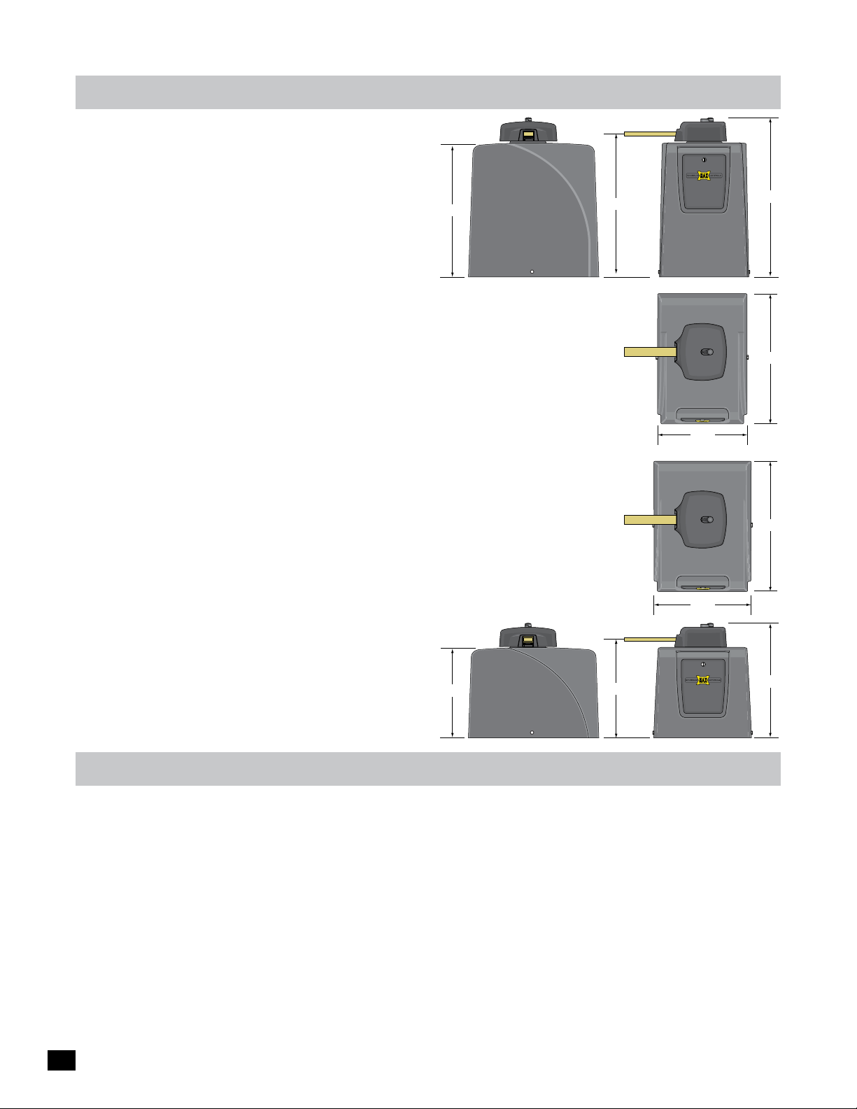
max megatron specifications
25.2”
UL 325 Class of Operation - Class I, II, III, IV
Gate Type - Vehicular Swing Gate
1400HP
(High Profile)
Max Gate Weight / Length:
- MAX Megatron 1400/1400HP - 1400lbs @ 15 ft or 1200 lbs @ 20 ft
- MAX Megatron 2200 - 2200lbs @ 15 ft or 1500 lbs @ 20 ft
- MAX Megatron FAST - 1600lbs @ 12 ft gate per operator
NOTE: The MAX Megatron FAST is ONLY available for installation on bi-parting gates (dual operators).
A single gate operator CANNOT be used.
90° Opening Time:
- MAX Megatron 1400/1400HP/2200 - 16 selectable speeds from approximately
11.5 sec to 20 sec depending on the weight and length of the gate.
- MAX Megatron FAST - 16 selectable speeds from approximately
6 sec to 14 sec depending on the weight and length of the dual gates.
Cycles per Hour AC Input Power - Continuous
Battery Back-Up Cycles (BC-7 Battery Module-7 Amp/Hr Batteries fully charged):
- Approximately 450 cycles
NOTE: The number of gate cycles using ONLY battery back-up power will vary depending on the
weight of the gate, the gate length, the operating condition of the gate hardware, temperature and
the amount of charge the batteries have at the beginning of the battery power only operation.
Input AC Power - Switchable: 115VAC or 230VAC single phase
Motor - 24VDC Brushless (equivalent to 1 HP AC motor)
Operating Temperature: -4°F to 158°F (-20°C to 70°C)
Entrapment Protection:
- UL 325 Type A Inherent (ERD sensor)
- Inputs for NORMALLY CLOSED (N.C.)
17”
UL 325 Type B1 (photo cell)
and Type B2 (sensing edge)
26.6”
18.5”
29.9”
1400HP
24.5”
1400HP
16.8”
24.5”
18.3”
21.3”
important safety information
WARNING – To reduce the risk of injury or death:
1. READ AND FOLLOW ALL INSTRUCTIONS.
2. Never let children operate or play with gate controls. Keep the remote control away from children.
3. Always keep people and objects away from the gate. NO ONE SHOULD CROSS THE PATH OF THE MOVING GATE.
4. Test the gate operator monthly. The gate MUST reverse on contact with a rigid object or stop when an object activates the
non-contact sensors. After adjusting the force or the limit of travel, retest the gate operator. Failure to adjust and retest the
gate operator properly can increase the risk of injury or death.
5. Use the emergency release only when the gate is not moving.
6. KEEP GATES PROPERLY MAINTAINED. Read the owner’s manual. Have a qualified service person make repairs to gate
hardware.
7. The entrance is for vehicles only. Pedestrians must use separate entrance.
8. SAVE THESE INSTRUCTIONS
2
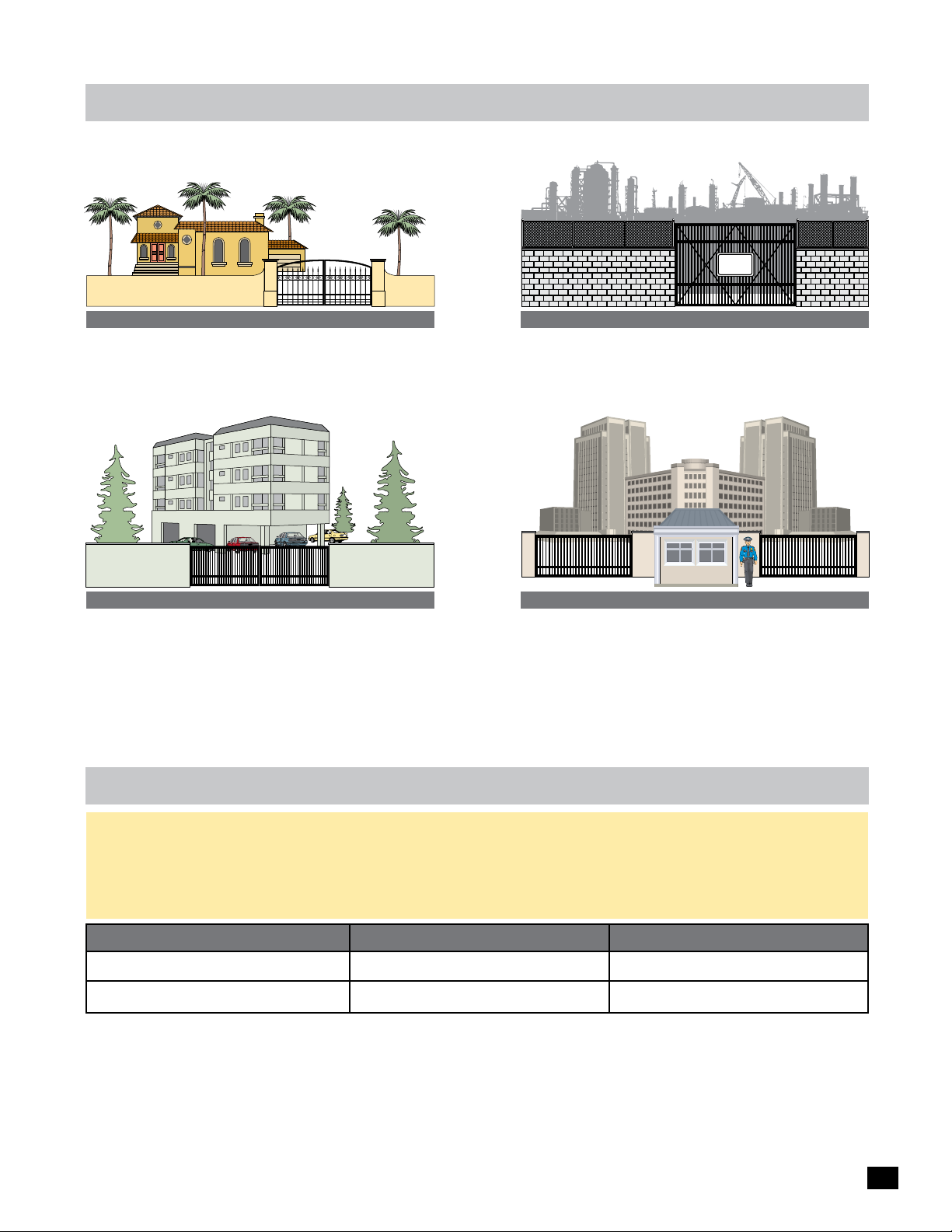
ul 325 model classifications
AUTHORIZED
PERSONNEL
ONLY
CLASS I
Residential Vehicular Gate Operator - A vehicular gate operator
(opener or system) intended for use in a home of one to four
single family dwellings, or a garage or parking area associated
therewith.
CLASS II
Commercial/General Access Vehicular Gate Operator - A
vehicular gate operator (opener or system) intended for use in
a commercial location or building such as a multi-family
housing unit (five or more single family units) hotel, garages,
retail store or other building servicing the general public.
CLASS III
Industrial/Limited Access Vehicular Gate Operator - A
vehicular gate operator (opener or system) intended for uses
in an industrial location, loading dock area or other location
not intended to service the general public.
SECURITY
CLASS IV
Restricted Access Vehicular Gate Operator - A vehicular gate
operator (opener or system) intended for use in a guarded
industrial location or buildings such as airport security area or
other restricted access locations not servicing the general
public, in which unauthorized access is prevented via
supervision by security personnel.
ul 325 required entrapment protection
This vehicular gate operator must be installed with at least two independent entrapment protection means as specified in the table and
definitions below.
The same type of device shall not be used for both entrapment protection means. Use of a single device to cover both the opening and
closing directions is in accordance with the requirement, however, a single device is not required to cover both directions. This operator
has been provided with type A entrapment protection. The installer is required to install additional entrapment protection devices in each
entrapment area.
Gate Type Class I & II
Swing Gate
Slide Gate
A - Inherent entrapment protection system.
B1 - Provision for connection of a non-contact sensor
(photoelectric sensor or the equivalent).
B2 - Provision for connection of a contact sensor
(edge device or the equivalent).
A, B1*, B2*, C, D
A, B1*, B2*, D
* B1 and B2 means of entrapment protection must be MONITORED.
C - Inherent adjustable clutch or pressure relief device.
D - Provision for connection of an actuating device
requiring continuous pressure to maintain opening
or closing motion of the gate.
E - An audio alarm.
Class III & IV
A, B1*, B2*, C, D, E
A, B1*, B2*, D, E
3

ul 325 compliant
installation requirements
A Install the gate operator only when:
1 The operator is appropriate for the construction of the gate and the usage Class of the gate,
2 All openings of a horizontal slide gate are guarded or screened from the bottom of the gate to a minimum of 6 feet (1.83 m) above the
ground to prevent a 2-1/4 inch (57.2 mm) diameter sphere from passing through the openings anywhere in the gate, and in that
portion of the adjacent fence that the gate covers in the open position,
3 All exposed pinch points are eliminated or guarded, and
4 Guarding is supplied for exposed rollers.
B The operator is intended for installation only on gates used for vehicles. Pedestrians must be supplied with a separate access opening. The
pedestrian access opening shall be designed to promote pedestrian usage. Locate the gate such that persons will not come in contact with
the vehicular gate during the entire path of travel of the vehicular gate.
C The gate must be installed in a location so that enough clearance is supplied between the gate and adjacent structures when opening and
closing to reduce the risk of entrapment. Swinging gates shall not open into public access areas.
D The gate must be properly installed and work freely in both directions prior to the installation of the gate operator. Do not over-tighten the
operator clutch or pressure relief valve to compensate for a damaged gate.
E For gate operators utilizing Type D protection:
1 The gate operator controls must be placed so that the user has full view of the gate area when the gate is moving,
2 A gate operator shall additionally be provided with a placard that is marked in letters at least 1/4-in (6.4-mm) high with the word
“WARNING” and the following statement or the equivalent: “Moving Gate Has Potential of Inflicting Injury or Death - Do Not Start
Gate Unless Path is Clear”.
3 An automatic closing device (such as a timer, loop sensor, or similar device) shall not be employed, and
4 No other activation device shall be connected.
F Controls intended for user activation must be located at least six feet (6’) away from any moving part of the gate and where the user is
prevented from reaching over, under, around or through the gate to operate the controls. Outdoor or easily accessible controls shall have a
security feature to prevent unauthorized use.
The Stop and/or Reset button must be located in the line-of-sight of the gate. Activation of the reset control shall not cause the operator to start.
G
H A minimum of two (2) WARNING SIGNS shall be installed, one on each side of the gate where easily visible.
I For gate operators utilizing a non-contact sensor:
1 See instructions on the placement of non-contact sensors for each Type of application,
Care shall be exercised to reduce the risk of nuisance tripping, such as when a vehicle, trips the sensor while the gate is still moving, and
2
3 One or more non-contact sensors shall be located where the risk of entrapment or obstruction exists, such as the perimeter reachable
by a moving gate or barrier.
J For a gate operator utilizing a contact sensor:
1 One or more contact sensors shall be located where the risk of entrapment or obstruction exists, such as at the leading edge, trailing
edge, and post mounted both inside and outside of a vehicular horizontal slide gate.
2 One or more contact sensors shall be located at the bottom edge of a vehicular vertical lift gate.
3 One or more contact sensors shall be located at the pinch point of a vehicular vertical pivot gate.
4 A hardwired contact sensor shall be located and its wiring arranged so that the communication between the sensor and the gate
operator is not subjected to mechanical damage.
5 A wireless device such as one that transmits radio frequency (RF) signals to the gate operator for entrapment protection functions
shall be located where the transmission of the signals are not obstructed or impeded by building structures natural landscaping or
similar obstruction. A wireless device shall function under the intended end-use conditions.
6 One or more contact sensors shall be located on the inside and outside leading edge of a swing gate. Additionally, if the bottom edge
of a swing gate is greater than 6 inches (152 mm) above the ground at any point in its arc of travel, one or more contact sensors shall
be located on the bottom edge.
7 One or more contact sensors shall be located at the bottom edge of a vertical barrier (arm).
4
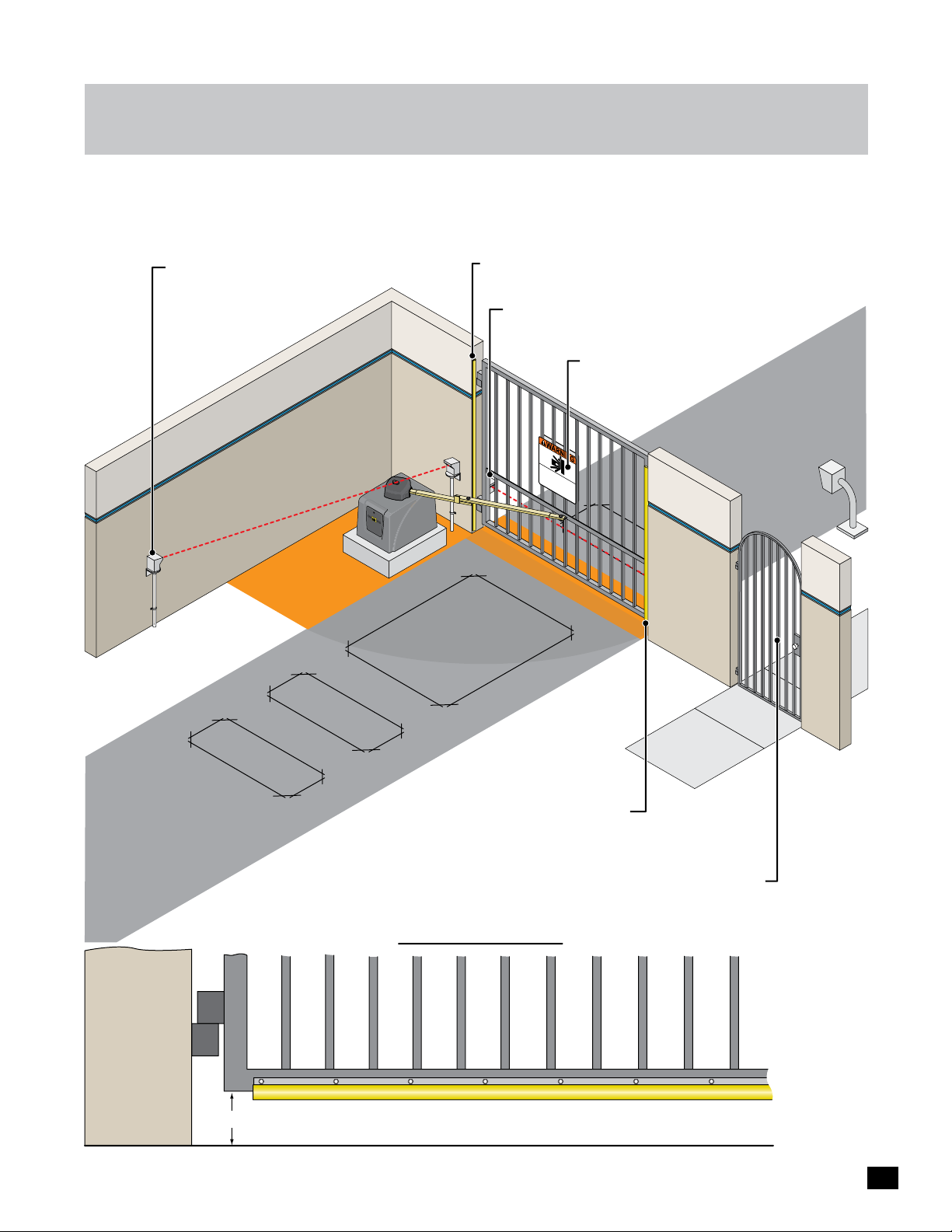
intended use of
swing gate operator
The operator is intended for use on a VEHICULAR slide gate ONLY. It is intended to be used WITH appropriate entrapment
protection safety devices and in-ground vehicle loop detection system. This operator has a inherent entrapment protection
system and requires additional external monitored entrapment protection devices (Non-contact Photocells or contact sensing
edges) for each entrapment area prior to gate operation.
Opening Direction Photocell: Helps
guard against the opening gate from
entrapment.
Area
Entrapment
Opening/Closing Direction 10K Sensing Edge: Helps
protect against entrapment in hinge area.
Closing Direction Photocell: Helps protect the gate
operator from accidentally closing on vehicles in the gate’s
closing path and entrapment.
Warning Signs: Should be installed
on both sides of gate area and
easily visible.
Moving Gate Can
Serious Inju
KEEP
w
it
C
hout
LE
Do not
AR!
prior
in
Ga
ry or Death
t
w
le
he gat
arning.
t
Caus
e ma
t
c
This
hildren operate
e area.
y
Pedes
entranc
m
ov
e
e at any
trians
e is
fo
t
he gat
m
time
r ve
us
t
hic
us
e or
e
les
s
play
eparate entranc
only.
e.
Entrapment Area
In-Ground Loops:
Help protect the gate
operator from accidentally
opening and/or closing on
vehicles in the gate’s path.
6” or More
Opening/Closing Direction 10K Sensing Edge: Helps
protect the gate operator from accidentally opening
and/or closing on vehicles in the gate’s path.
(Wireless Option)
Pedestrians MUST use a separate entrance.
The gate operator IS NOT intended to be
used on a PEDESTRIAN gate.
Bottom of Gate
NOTE: sensors
MUST be
MONITORED
and NORMALLY
CLOSED (N.C.)
OPENING/CLOSING direction Gate Protection 10K Sensing Edge on Bottom of Gate: If the bottom of
gate is 6 inches or higher above the ground, then a sensing edge should be installed for safety.
5
installation
Read and understand this entire manual before installation. Check with the local building department prior to installing this gate
operator to comply with local building code requirements. The gate must be installed in a location so that enough clearance is
supplied between the gate and adjacent structures when opening and closing to reduce the risk of entrapment. Swinging gates
should not open into public access areas.
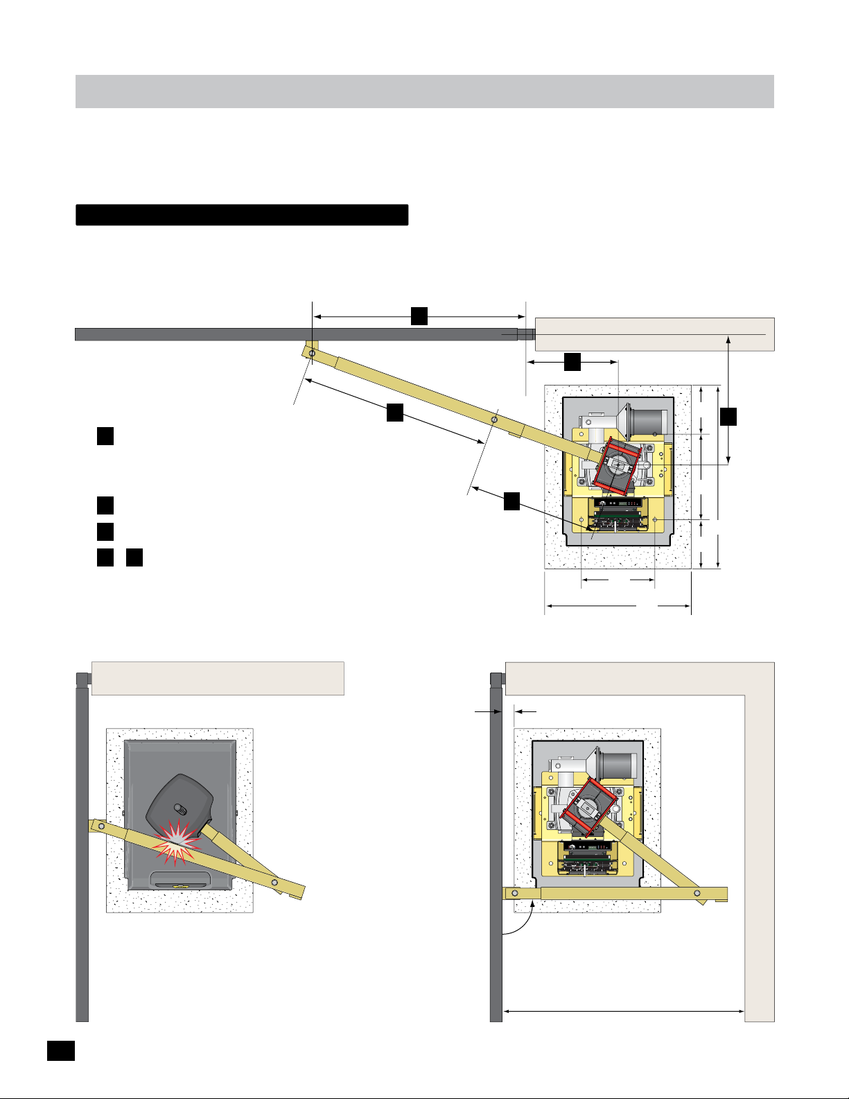
Gate Operator position
The gate must be properly installed and work freely in both directions prior to installation of the gate operator.
Closed Position
Gate Bracket Pivot Point
A
Hinge Pivot Point
Illustrations not to scale
Measurement Guidelines
A Should be at least 1/4 the gate length.
NOTE: Uphill or heavy gates should be at least
1/3 gate length.
B 15” minimum for open gate clearance (2” thick gate).
C Distance “A” minus 17 inches (A - 17 = C).
D & E Arm should be 90° from gate when OPEN
and in the straight “locked” position when CLOSED.
Maximum arm length is 71 inches.
Open Position
Locked Position
Long Arm
D
Longer
than “E”
Arm
Pivot
Point
E
Shorter
than “D”
15” Min
Short Arm
2” Min
B
Concrete Pad
8”
C
Operator
LIMIT
LIMIT
CLOSED
OPEN
ERD
MC-200
JOG
Sensitivity
JOG
Motor Controller
Motor
GND
Cell
MATRIX
Photo
LEFT
RIGHT
Jog LT
Edge 1
Edge 2
ON-LINE
UL Entrap
Edge
OverLoad
Jog RT
5
4
1
3
POWER
MAX
2
ERD
12
16
LED ON
Edge
PhotoCell
Limit SW
13
15
14
POWER
POWER/SOLAR
IN
IN
TO MOTOR
CONTROLLER
BATTERY
BATTERY
BATTERY
MATRIX 1
PRIMARY
BACK-UP MODE
GATE
LEAVE
MAGLOCK
CLOSED
DELAY
OPEN
OPEN
PACK
IN
LEAVE
OPEN
MADE in USA
MAG
RIGHT
LEFT
OPEN
1 TIME
OFF
2Sec1.5Sec
LOCK
COM
NC
AUTOMATIC OPEN/CLOSE CONTROLS
Tamper NO
ANTI
GATE
SAFETYCENTEREXIT
TAILGATE
COM
TAMPER
GND
EXIT
OFFON
Tamper IN
CENTER
PHOTOCELL
UL
EDGE 1
SAFETY
MIN
MAX
OFF
ENTRAP
EDGE 2
CLOSE TIMER
ID PLUG
PARTIAL
MOTOR MOTION
ERROR
OPEN
ID
PLUG
UL ALARM 12V
ALARM RET
RESET
OPEN
STOPCLOSE
GND
POSITION
RECORDER
REVERSE SENSITIVITY
MAX
12VDC
GATE SPEED
MOTOR OVERLOAD
GND
OBD PORT
OPEN
BLACK BOX
GATE
MIN
NO LIMIT SWITCH /
COM
STATUS
CLAMP SLIPPING
24VDC
MAX
CLOSE
GND
LIMIT
BATTERY
SWITCH
ON-LINE
IN USE
MOTOR
ON-LINE
POWER
PRIMARY
SEC
GATE
GATE
24V
GND
PHOTOCELL
GND
STRIKE
GND
KEYPAD / RDR
GND
FIRE DEPT
GND
MAX OPEN
GND
RADIO SIG.
RADIO GND
OPEN
STOP
CLOSE
COM
GATE DISABLE
(+)
GND
(-)
(+)
GND
(-)
www.max.us.com
Made in USA
12”
24”
Outside Property
Inside Property
14”
8”
Pivot
Point
30”
Hood
LIMIT
LIMIT
CLOSED
2” Gate Frame
OPEN
ERD
MC-200
JOG
Sensitivity
JOG
Motor Controller
Motor
GND
Cell
MATRIX
Photo
LEFT
RIGHT
Jog LT
Edge 1
Edge 2
ON-LINE
UL Entrap
Edge
OverLoad
Jog RT
5
4
1
3
POWER
MAX
2
ERD
12
16
LED ON
Edge
PhotoCell
Limit SW
13
15
14
POWER
POWER/SOLAR
IN
IN
TO MOTOR
CONTROLLER
BATTERY
BATTERY
BATTERY
MATRIX 1
PRIMARY
BACK-UP MODE
GATE
LEAVE
MAGLOCK
CLOSED
DELAY
OPEN
OPEN
PACK
IN
LEAVE
OPEN
MADE in USA
MAG
RIGHT
LEFT
OPEN
1 TIME
OFF
2Sec1.5Sec
LOCK
COM
NC
AUTOMATIC OPEN/CLOSE CONTROLS
Tamper NO
ANTI
GATE
SAFETYCENTEREXIT
TAILGATE
COM
TAMPER
GND
EXIT
OFFON
Tamper IN
CENTER
PHOTOCELL
UL
EDGE 1
SAFETY
MIN
MAX
OFF
ENTRAP
EDGE 2
CLOSE TIMER
ID PLUG
PARTIAL
MOTOR MOTION
ERROR
OPEN
ID
PLUG
UL ALARM 12V
ALARM RET
RESET
STOPCLOSE
OPEN
GND
POSITION
RECORDER
REVERSE SENSITIVITY
MAX
12VDC
GATE SPEED
MOTOR OVERLOAD
GND
OBD PORT
OPEN
BLACK BOX
GATE
MIN
NO LIMIT SWITCH /
COM
STATUS
CLAMP SLIPPING
24VDC
MAX
CLOSE
GND
LIMIT
BATTERY
SWITCH
ON-LINE
IN USE
MOTOR
ON-LINE
POWER
PRIMARY
SEC
GATE
GATE
24V
GND
PHOTOCELL
GND
STRIKE
GND
KEYPAD / RDR
GND
FIRE DEPT
GND
MAX OPEN
GND
RADIO SIG.
RADIO GND
OPEN
STOP
CLOSE
COM
GATE DISABLE
(+)
GND
(-)
(+)
GND
(-)
www.max.us.com
Made in USA
Preferred arm position
is 90° from open gate.
DO NOT allow arm to touch
hood in gate’s OPEN position.
TOO MUCH STRESS is put on
the arm in this position during
gate operation.
See page 10 for arm
position options and
connection to gate.
NOTE: If dimension between OPEN gate
and wall is 20” to 32” then compact
installation is necessary, see page 12.
Wall
6
installation
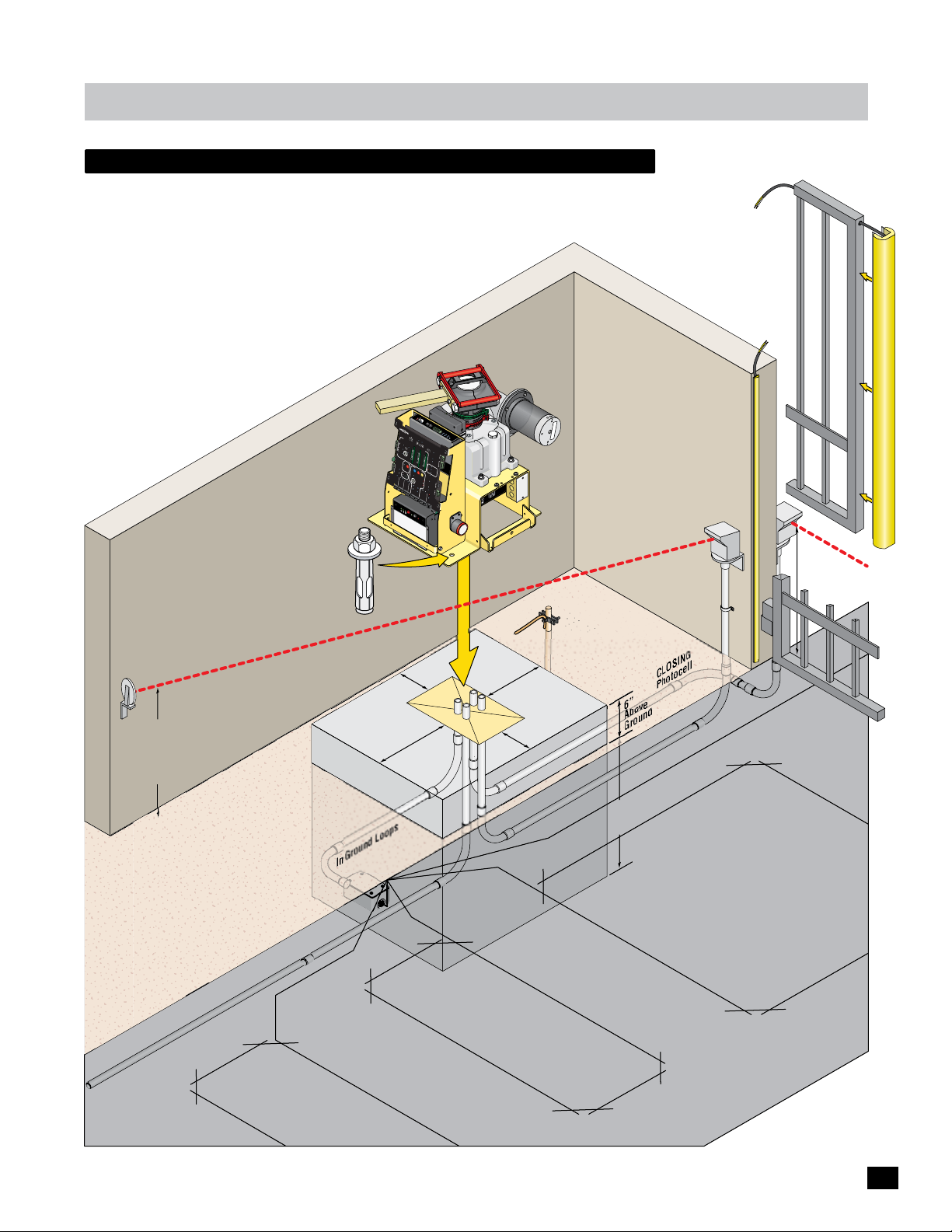
recommended Gate Operator layout
Use for VEHICULAR traffic ONLY. Pedestrians MUST use a separate
entrance. Install appropriate entrapment protection safety devices
for the OPENING direction and CLOSING direction of gate cycling.
Install in-ground SAFETY and CENTER loops. Install a GROUNDING
ROD within 10 ft of operator. An “Optional” EXIT loop can be
installed if desired.
NOTE: ONE Entrapment protection
sensor MUST installed or operator
will NOT function. It MUST be
MONITORED and NORMALLY
CLOSED (N.C.)
O
M
verL
o
to
r
o
ad
E
S
E
RD
e
RD
n
s
i
t
i
v
i
t
y
5
1
2
4
1
3
3
1
4
1
1
5
6
JO
M
LE
G
AX
L
E
F
D
T
O
N
JO
R
G
IG
H
T
T
L
T
g
MA
o
R
J
og
1
T
J
GND
R
e
2
I
dg
e
X
o
E
dg
ot
1
E
h
l
l
P
e
C
MA
O
T
N
R
MA
-
I
LI
X
B
N
DE
E
A
BAC
TT
i
n
US
E
E
L
d
K-
i
R
mi
A
g
1
e
Y
t
U
S
W
P
M
U
2
L
M
o
E
n
to
MC
L
O
t
r
E
L
E
ap
d
E
DE
A
r
g
A
V
e
C
Co
V
E
L
E
-
OP
OS
P
2
POWE
h
ntr
o
E
E
t
0
D
o
C
o
0
e
l
PR
lle
l
r
I
R
M
OP
AR
E
N
G
1
Y
ATE
T
I
ME
O
P
E
N
L
E
F
IC
T
O
P
O
EN
R
PEN/CLO
I
G
H
T
M
AG
D
L
R
O
A
SE CO
DE
CK
O
X
I
EXIT
O
B
LA
R
F
F
T
Y
A
PWR 24V -
1
.
M
5
S
N
ec
T
RS-485 (-) -
ROL
2
RS-485 (+) -
S
ec
CENT
M
AG
GND -
S
E
LOCK
R
SAF
E
T
COM
Y
NC
GA
M
TE
R
A
T
L
A
A
M
Ta
PE
CH
m
T
I
W
R
pe
S
T
I
r
M
I
NO
L
K
C
A
P
Y
R
E
CO
T
T
A
B
M
S
T
U
G
P
Tam
N
ND
I
R
O
T
O
pe
M
r
IN
r In
e
w
Po
PH
MOT
U
OT
L
O
OCE
R
MO
L
R
L
T
O
I
ENTR
O
N
OT
EDG
A
M
P
E
1
OPE
N
E
MAX
DG
E
ST
2
OP
GA
ID PLUG
TE
CLOS
R
S
E
M
PEED
V
I
ERRO
N
E
R
E
S
E
S
MA
E
R
N
X
S
I
M
T
U
I
O
V
L
T
I
T
ALAR
OR
Y
OV
E
RL
ALAR
M
NO
O
12
A
L
D
I
MI
V
M
C
T
L
RE
A
S
MP
W
I
RE
T
T
S
C
L
H
I
S
P
/
P
E
I
T
NG
GN
LI
G
MIT
D
L
AT
S
W
L
E
ITCH
ST
ON
E
AT
-L
I
U
NE
S
OC
M
T
OTO
ON-LIN
OPE
P
R
RI
M
N
A
R
E
GA
Y
CO
T
E
GND
M
CLOS
D
S
(+)
N
E
C
G
E
)
GA
-
T
(
E
E
L
D
BA
+)
(
B
N
TT
N
G
A
E
-)
R
E
E
(
S
Y
I
N
OP
US
DI
OP
T
OS
E
S
L
E
C
OM
T
PO
C
W
GA
ER
V
D
4
2
GN
MA
F
F
Ba
X
R
t
t
B
epl
er
r
y
C
y
ac
M
-
B
e
o
7
a
d
t
u
ter
l
e
T
y
ES
T
Ba
t
t
Ba
e
r
y
t
te
r
y
IN
E
r
r
or
:
G
N
I
,
N
e
R
ir
f
t
a
s
WA
in
e
a
p
g
ty
a
e
m
a
s
SSEMENT
I
T
t
t
e
m
VER
o
c
r
A
p
’in
d
m
o
s
t
c
e
s
u
e
q
m
is
r
ê
.
s
m
e
l
e
a
d
n
i
m
o
n
p
Am
7
E
S
FU
n
O
ER
W
O
P
15
1
f
f
O
Illustration not to scale
Secure gate operator
to concrete pad with
six (6) 1/2” x 3” (min)
sleeve anchors.
N
AU
T
O
M
A
T
AN
E
X
T
T
I
T
AI
I
LG
AT
E
ON
O
F
C
F
E
NT
E
R
S
A
F
E
T
Y
MI
N
O
M
F
A
F
CLOSE TI
X
I
D
M
ER
PLUG
P
A
R
T
IAL
O
P
E
N
1
2
V
DC
GN
D
POSI
RE
T
IO
2
CO
4
V
N
DC
R
DE
G
ND
R
OB
D
B
POR
L
A
C
T
K
BO
X
G.
I
D
S
O
GN
T
DI
P
O
N
DI
E
RA
DE
R
RA
OP
RE
D
I
RD
X
F
E
/
A
GN
K
D
M
A
RI
GND
T
P
S
Y
E
GND
K
GND
HO
P
B
a
t
t
e
r
y
V
E
o
lt
a
g
1
e
/
2
F
O
N
/O
Batte
1/2
Run wiring to
GA
TE OPERATOR
10K Sensing Edge
Mount on end of gat
.
and hinge area.
Run wiring to
GA
TE OPER
e
ATOR.
Max Mini Edge
Support Bar
n
io
t
c
e
t
o
r
e
p
d
th
e
h
u
it
in
t
w
n
y
.
l
o
e
c
n
s
r
o
u
o
f
e
f
c
F
s
o
s
la
a
le
g
p
p
re
e
tin
re
t
a
n
r
n
r
le
o
u
d
c
ib
o
n
s
n
p
u
:
io
f
t
s
n
c
e
e
u
t
u
r
o
e
r
iq
t
p
is
ilis
t
r
la
u
é
t
e
,
c
r
ie
a
r
d
a
n
e
c
t
e
e
p
y
x
a
m
A
3
C
A
V
CLOSING
Photocell Beam
21” Hig
h
Gr
Rod
oun
d
Support Bar
OPENING Photocell Beam
Beam
Height
ust
J
Above
Gate
Operator
t AC Power (Required)
Inpu
24”x 30”
Pad
In-Ground Loops
Exit Loop
(Optional)
5.5
12”
10”
”
Conduit
12” x 8.5”
Area
5.5
”
NING Ph
OPE
oto
cell
6”
Abov
G
24”
Min
e
round
CLOSING
Photocel
l
om Safety Loop
r
F
Center Loop
Safety Loop
7
installation
YES
NO
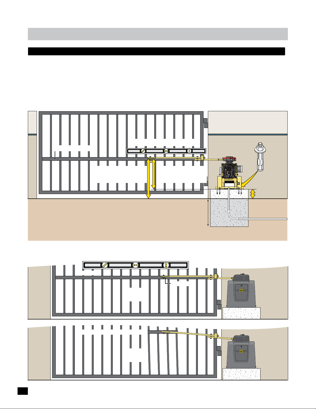
layout and arm height of 1400/2200/FAST or 1400hp
The gate must be properly installed and work freely in both directions prior to the installation of the gate operator.
See “Gate Operator Position” on page 6 for operator position and “Arm Connection to Gate” on page 10.
Conduit Guidelines and Suggestions (See page 7)
• REQUIRED - AC input power wire.
• REQUIRED - Entrapment protection (photocell and/or sensing edge). See page 13.
• Normally open photocell. See page 13.
• In-ground loop wires. See page 14.
Illustration not to scale
Secure gate operator
Support Bar: See below
Arm MUST be installed level.
1400/2200/FAST = 25”
1400HP = 33.5”
19”=1400/2200/FAST
27.5”=1400HP
to concrete pad with
six (6) 1/2” x 3”
(min) sleeve anchors.
PRIMARY
BATTERY
MATRIX 1
GATE
BACK-UP MODE
LEAVE
MAGLOCK
CLOSED
DELAY
OPEN
OPEN
LEAVE
OPEN
MADE in USA
MAG
RIGHT
LEFT
OPEN
1 TIME
OFF
2Sec1.5Sec
LOCK
COM
NC
AUTOMATIC OPEN/CLOSE CONTROLS
Tamper NO
ANTI
GATE
SAFETYCENTEREXIT
TAILGATE
COM
TAMPER
GND
BOARD
EXIT
OFFON
Tamper IN
MATRIX
CENTER
RS-485 (+) -
PHOTOCELL
RS-485 (-) -
PWR 24V -
UL
EDGE 1
SAFETY
MIN
MAX
OFF
ENTRAP
EDGE 2
GND -
CLOSE TIMER
ID PLUG
PARTIAL
MOTOR MOTION
ERROR
OPEN
ID
INPUTS
PACK
SWITCH
Power In
MOTOR
MOTOR
PLUG
BATTERY
ALARM
LIMIT
UL ALARM 12V
ALARM RET
RESET
OPEN
STOP CLOSE
POSITION
GND
RECORDER
REVERSE SENSITIVITY
MAX
12VDC
GATE SPEED
MOTOR OVERLOAD
GND
OBD PORT
OPEN
BLACK BOX
GATE
MIN
NO LIMIT SWITCH /
COM
STATUS
24VDC
CLAMP SLIPPING
MAX
CLOSE
GND
LIMIT
BATTERY
SWITCH
ON-LINE
IN USE
MOTOR
ON-LINE
POWER
PRIMARY
SEC
GATE
GATE
24V
GND
PHOTOCELL
GND
STRIKE
GND
KEYPAD / RDR
GND
FIRE DEPT
GND
MAX OPEN
GND
RADIO SIG.
RADIO GND
OPEN
STOP
CLOSE
COM
GATE DISABLE
(+)
GND
(-)
(+)
GND
(-)
MAX BC-7
Battery Voltage
Battery Module
EF1/2
ON/OFF
Replace
TEST
Battery IN
Battery
Battery
Battery
Error
1/2
6” Above Ground
Ground Level
Check local building
codes in your area for
“Optional” Input Power Note:
24VDC low voltage power wires can be run
from a remote power supply (MAX Magic
Box) to power the gate operator if desired.
See page 11 for more information.
Concrete Depth Note: The heavier the gate, the deeper the concrete
pad should be. At least two feet recommended for heavier gate.
depth of concrete
before installation.
Concrete Pad
Conduit
Input Power
Support Bar
A support bar should be installed at the gate bracket height across the ENTIRE gate to keep the gate pickets from bending.
Support Bar
Gate Bracket
YES
Support Bar Too High & Not Long Enough
NO
8
installation
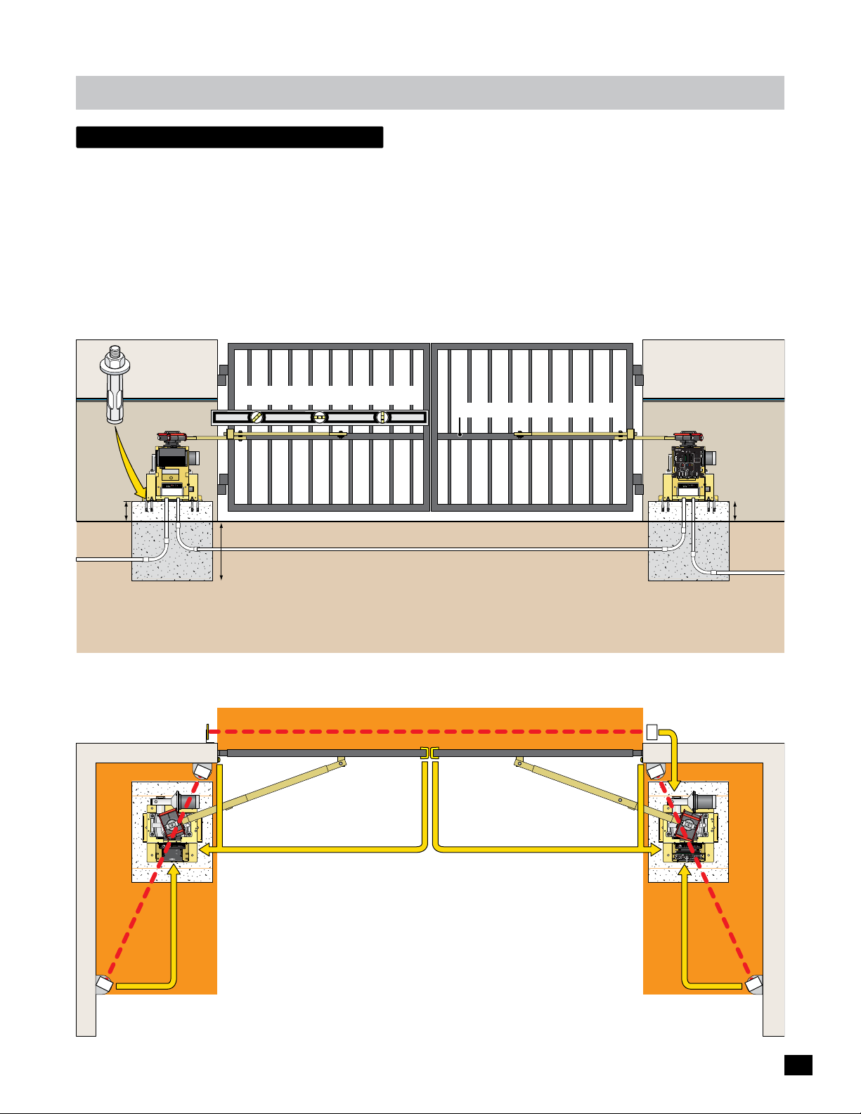
dual Gate Operators
The gates must be properly installed and work freely in both directions prior to the installation of the dual gate operators.
See “Gate Operator Position” on page 6 for operator positions and previous page for arm height.
Conduit Guidelines and Suggestions
• REQUIRED - Run AC input power wire to EACH gate operator.
• REQUIRED - Entrapment protection (photocell and/or sensing edge) to EACH Corresponding
GATE OPERATOR. (see below & page 13)
Secure EACH gate
operator to concrete pad
with six (6) 1/2”x 3” (min)
sleeve anchors.
Secondary
Operator
1/2
NO Matrix 1
BOARD
MATRIX
RS-485 (+) -
RS-485 (-) -
PWR 24V -
GND -
INPUTS
PACK
SWITCH
MOTOR
BATTERY
ALARM
LIMIT
MAX BC-7
Battery Voltage
Battery Module
EF1/2
ON/OFF
Replace
TEST
Battery IN
Battery
Battery
Battery
Error
6” Above
Ground
Power In
MOTOR
• Normally open photocell to the PRIMARY OPERATOR. (page 13)
• In-ground loop wires to the PRIMARY OPERATOR. (page 14)
Arms MUST be installed level.
Support Bars: See bottom of page 8.
Illustration not to scale
Primary
Operator
Matrix 1
BATTERY
MATRIX 1
PRIMARY
BACK-UP MODE
GATE
LEAVE
MAGLOCK
CLOSED
DELAY
OPEN
OPEN
LEAVE
OPEN
MADE in USA
MAG
RIGHT
LEFT
OPEN
1 TIME
OFF
2Sec1.5Sec
LOCK
COM
NC
AUTOMATIC OPEN/CLOSE CONTROLS
Tamper NO
ANTI
GATE
SAFETYCENTEREXIT
TAILGATE
COM
TAMPER
GND
BOARD
EXIT
OFFON
Tamper IN
MATRIX
CENTER
RS-485 (+) -
PHOTOCELL
RS-485 (-) -
PWR 24V -
UL
EDGE 1
SAFETY
MAX
MIN
OFF
ENTRAP
EDGE 2
GND -
CLOSE TIMER
ID PLUG
PARTIAL
MOTOR MOTION
ERROR
OPEN
ID
INPUTS
PACK
SWITCH
Power In
MOTOR
MOTOR
PLUG
BATTERY
ALARM
LIMIT
UL ALARM 12V
ALARM RET
RESET
OPEN
STOPCLOSE
POSITION
GND
RECORDER
REVERSE SENSITIVITY
MAX
12VDC
GATE SPEED
MOTOR OVERLOAD
GND
OBD PORT
OPEN
BLACK BOX
GATE
MIN
NO LIMIT SWITCH /
COM
STATUS
CLAMP SLIPPING
24VDC
MAX
CLOSE
GND
LIMIT
BATTERY
SWITCH
ON-LINE
IN USE
MOTOR
ON-LINE
POWER
PRIMARY
SEC
GATE
GATE
24V
GND
PHOTOCELL
GND
STRIKE
GND
KEYPAD / RDR
GND
FIRE DEPT
GND
MAX OPEN
GND
RADIO SIG.
RADIO GND
OPEN
STOP
CLOSE
COM
GATE DISABLE
(+)
GND
(-)
(+)
GND
(-)
MAX BC-7
Battery Voltage
Battery Module
EF1/2
ON/OFF
Replace
TEST
Battery IN
Battery
Battery
Battery
Error
6” Above
Ground
Conduit
Input
Power
Concrete Depth Note: The heavier the gates, the deeper the concrete
pads should be. At least two feet recommended for heavier gates.
Check local building codes in your area for
depth of concrete before installation.
Conduit
Input
“Optional” Input Power Note:
Power
24VDC low voltage power wires can be run from a remote
power supply (MAX Magic Boxes) to power the gate
operators if desired. See page 11 for more information.
Each entrapment protection device MUST be connected to corresponding gate operator.
Dual Gates CLOSING direction Thru-Beam Photocell ONLY:
See separate wiring instruction sheet.
To Matrix 1 SEC GATE input Conduit
Reflector
Illustrations not to scale
LIMIT
LIMIT
CLOSED
OPEN
ERD
JOG
Sensitivity
JOG
GND
Cell
Motor Controller
Motor
MATRIX
Photo
Jog LT
Edge 1
Edge 2
LEFT
RIGHT
Jog RT
ON-LINE
Edge
UL Entrap
OverLoad
5
4
1
3
MAX
2
ERD
12
16
LED ON
Edge
PhotoCell
Limit SW
13
15
14
POWER
POWER/SOLAR
IN
IN
TO MOTOR
CONTROLLER
BATTERY
BATTERY
PACK
IN
www.max.us.com
Made in USA
Entrapment Area
Entrapment Area
OPENING/CLOSING direction Sensing Edges
OPENING/CLOSING
direction Mini
Sensing Edge
to Secondary Operator
MC-200
POWER
MC-200 Edge 2 or Photo Cell
Secondary Operator
NO Matrix 1
to Secondary Operator
MC-200 Edge 2 or Photo Cell
CLOSING direction Photocell
OPENING/CLOSING
direction Mini
Sensing Edge
to Primary Operator
MC-200 Edge 2 or Photo Cell
Primary Operator
Matrix 1
to Primary Operator
MC-200 Edge 2 or Photo Cell
To MC-200 EDGE 1 Input
Entrapment Area
LIMIT
LIMIT
CLOSED
OPEN
ERD
MC-200
JOG
Sensitivity
JOG
GND
Cell
Motor Controller
Motor
MATRIX
Photo
Jog LT
Edge 1
Edge 2
LEFT
RIGHT
Jog RT
ON-LINE
Edge
UL Entrap
OverLoad
5
4
1
3
POWER
MAX
2
ERD
12
16
LED ON
Edge
PhotoCell
Limit SW
13
15
14
POWER
POWER/SOLAR
IN
IN
TO MOTOR
CONTROLLER
BATTERY
BATTERY
BATTERY
MATRIX 1
PRIMARY
BACK-UP MODE
GATE
LEAVE
MAGLOCK
CLOSED
DELAY
OPEN
OPEN
PACK
IN
LEAVE
OPEN
MADE in USA
MAG
RIGHT
LEFT
OPEN
1 TIME
OFF
2Sec1.5Sec
LOCK
COM
NC
AUTOMATIC OPEN/CLOSE CONTROLS
Tamper NO
ANTI
GATE
SAFETYCENTEREXIT
TAILGATE
COM
TAMPER
GND
EXIT
OFFON
Tamper IN
CENTER
PHOTOCELL
UL
EDGE 1
SAFETY
MIN
MAX
OFF
ENTRAP
EDGE 2
CLOSE TIMER
ID PLUG
PARTIAL
MOTOR MOTION
ERROR
OPEN
ID
PLUG
UL ALARM 12V
ALARM RET
RESET
STOPCLOSE
OPEN
POSITION
GND
RECORDER
REVERSE SENSITIVITY
MAX
12VDC
GATE SPEED
MOTOR OVERLOAD
GND
OBD PORT
OPEN
BLACK BOX
GATE
MIN
NO LIMIT SWITCH /
COM
STATUS
CLAMP SLIPPING
24VDC
MAX
CLOSE
GND
LIMIT
BATTERY
SWITCH
ON-LINE
IN USE
MOTOR
ON-LINE
POWER
PRIMARY
SEC
GATE
GATE
24V
GND
PHOTOCELL
GND
STRIKE
GND
KEYPAD / RDR
GND
FIRE DEPT
GND
MAX OPEN
GND
RADIO SIG.
RADIO GND
OPEN
STOP
CLOSE
COM
GATE DISABLE
(+)
GND
(-)
(+)
GND
(-)
www.max.us.com
Made in USA
OPENING direction Photocell OPENING direction Photocell
See page 13 for installation instructions.
See pages 17-18 for wiring instructions.
9

installation
arm position options
High Traffic Arm Option
Gates in Closed Position
Retro-Fit Arm Option
When replacing an existing gate operator, the arm may not be able
to conform to the preferred arm position (90° from gate in open
position). The positions illustrated below can be acceptable as long
as the gate operator cycles smoothly and there is NO gate hesitation
when gate starts cycling in either direction.
90°
Gate in Opened Position
90°
Gate in Opened Position
arm connection to gate
After you’re satisfied testing the arm in the FULL OPEN and FULL CLOSED positions, weld gate bracket and arm.
Illustrations not to scale
Full Closed
Arms are NOT installed in LOCKED position.
If a vehicle tries to push gates
open, arms will give when NOT
in the locked position and allow
gates to move without damaging
the gate operators.
The tamper relay will be
activated for a few seconds
which will trigger a camera or
alarm system if desired.
Locked Position
LIMIT
LIMIT
CLOSED
OPEN
MC-200
ERD
JOG
Sensitivity
JOG
GND
Motor Controller
Cell
Motor
MATRIX
Photo
Jog LT
Edge 1
LEFT
Edge 2
RIGHT
Jog RT
ON-LINE
Edge
UL Entrap
OverLoad
5
4
1
3
POWER
MAX
2
ERD
12
16
LED ON
PhotoCellEdge
Limit SW
13
15
14
POWER
POWER/SOLAR
IN
IN
TO MOTOR
CONTROLLER
BATTERY
BATTERY
PRIMARY
BATTERY
MATRIX 1
GATE
BACK-UP MODE
LEAVE
MAGLOCK
CLOSED
DELAY
OPEN
OPEN
PACK
IN
OPEN
LEAVE
MADE in USA
MAG
RIGHT
LEFT
1 TIME
OPEN
2Sec1.5Sec
OFF
LOCK
COM
NC
AUTOMATIC OPEN/CLOSE CONTROLS
Tamper NO
ANTI
GATE
SAFETYCENTEREXIT
TAILGATE
COM
TAMPER
GND
EXIT
OFFON
Tamper IN
CENTER
PHOTOCELL
UL
EDGE 1
SAFETY
MAX
MIN
OFF
ENTRAP
EDGE 2
CLOSE TIMER
ID PLUG
PARTIAL
MOTOR MOTION
ERROR
OPEN
ID
PLUG
UL ALARM 12V
ALARM RET
RESET
OPEN
STOPCLOSE
POSITION
GND
RECORDER
REVERSE SENSITIVITY
MAX
12VDC
GATE SPEED
MOTOR OVERLOAD
GND
OBD PORT
OPEN
BLACK BOX
GATE
MIN
NO LIMIT SWITCH /
COM
STATUS
24VDC
CLAMP SLIPPING
MAX
CLOSE
GND
LIMIT
BATTERY
SWITCH
ON-LINE
IN USE
MOTOR
POWER
ON-LINE
PRIMARY
SEC
GATE
GATE
24V
GND
PHOTOCELL
GND
STRIKE
GND
KEYPAD / RDR
GND
FIRE DEPT
GND
MAX OPEN
GND
RADIO SIG.
RADIO GND
OPEN
STOP
CLOSE
COM
GATE DISABLE
(+)
GND
(-)
(+)
GND
(-)
www.max.us.com
Made in USA
Full Open
Preferred arm position
is 90° from open gate.
Re-Attach Arm to Operator:
Limit pin MUST fit into slot in
bottom of release handle clamp
directly under the arm when
re-attaching arm to operator.
Release Handle Clamp
Arm
Limit Tabs
Slot
Limit Pin
weld completely around arm tubing and gate bracket.
Arm MUST be installed level.
Gate Bracket
Assembly
Arm Elbow
Assembly
ID
PLUG
12VDC
GND
24VDC
GND
MATRIX 1
MADE in USA
EXIT
CENTER
PWR 24V -
SAFETY
AUTOMATIC OPEN/CLOSE CONTROLS
ANTI
TAILGATE
RS-485 (-) -
MIN
GND -
CLOSE TIMER
FIRE DEPT
RADIO SIG.
RADIO GND
LIMIT
LIMIT
CLOSED
OPEN
MC-200
ERD
JOG
Sensitivity
JOG
GND
Motor Controller
Cell
Motor
MATRIX
Photo
Jog LT
Edge 1
LEFT
Edge 2
RIGHT
Jog RT
ON-LINE
Edge
UL Entrap
OverLoad
5
4
1
3
POWER
MAX
2
ERD
12
16
LED ON
PhotoCellEdge
Limit SW
13
15
14
POWER
POWER/SOLAR
IN
IN
TO MOTOR
CONTROLLER
BATTERY
BATTERY
PRIMARY
BATTERY
MATRIX 1
GATE
BACK-UP MODE
LEAVE
MAGLOCK
CLOSED
DELAY
OPEN
OPEN
PACK
IN
OPEN
LEAVE
MADE in USA
MAG
RIGHT
LEFT
1 TIME
OPEN
2Sec1.5Sec
OFF
LOCK
COM
NC
AUTOMATIC OPEN/CLOSE CONTROLS
Tamper NO
ANTI
GATE
SAFETYCENTEREXIT
TAILGATE
COM
TAMPER
GND
EXIT
OFFON
Tamper IN
CENTER
PHOTOCELL
UL
EDGE 1
SAFETY
MAX
MIN
OFF
ENTRAP
EDGE 2
CLOSE TIMER
ID PLUG
PARTIAL
MOTOR MOTION
ERROR
OPEN
ID
PLUG
UL ALARM 12V
ALARM RET
RESET
OPEN
STOPCLOSE
POSITION
GND
RECORDER
REVERSE SENSITIVITY
MAX
12VDC
GATE SPEED
MOTOR OVERLOAD
GND
OBD PORT
OPEN
BLACK BOX
GATE
MIN
NO LIMIT SWITCH /
COM
STATUS
24VDC
CLAMP SLIPPING
MAX
CLOSE
GND
LIMIT
BATTERY
SWITCH
ON-LINE
IN USE
MOTOR
POWER
ON-LINE
PRIMARY
SEC
GATE
GATE
24V
GND
PHOTOCELL
GND
STRIKE
GND
KEYPAD / RDR
GND
FIRE DEPT
GND
MAX OPEN
GND
RADIO SIG.
RADIO GND
OPEN
STOP
CLOSE
COM
GATE DISABLE
(+)
GND
(-)
(+)
GND
(-)
www.max.us.com
Made in USA
PRIMARY
BATTERY
GATE
BACK-UP MODE
LEAVE
MAGLOCK
CLOSED
DELAY
OPEN
OPEN
LEAVE
OPEN
MAG
RIGHT
LEFT
OPEN
1 TIME
OFF
2Sec1.5Sec
LOCK
COM
NC
Tamper NO
GATE
SAFETYCENTEREXIT
COM
TAMPER
GND
BOARD
OFFON
Tamper IN
MATRIX
RS-485 (+) -
PHOTOCELL
UL
EDGE 1
MAX
OFF
ENTRAP
EDGE 2
ID PLUG
PARTIAL
MOTOR MOTION
ERROR
OPEN
INPUTS
PACK
SWITCH
Power In
MOTOR
MOTOR
BATTERY
ALARM
LIMIT
UL ALARM 12V
ALARM RET
RESET
OPEN
STOP CLOSE
POSITION
GND
RECORDER
REVERSE SENSITIVITY
MAX
GATE SPEED
MOTOR OVERLOAD
OBD PORT
OPEN
BLACK BOX
GATE
MIN
NO LIMIT SWITCH /
COM
STATUS
CLAMP SLIPPING
MAX
CLOSE
LIMIT
BATTERY
SWITCH
ON-LINE
IN USE
MOTOR
ON-LINE
POWER
PRIMARY
SEC
GATE
GATE
24V
GND
PHOTOCELL
GND
STRIKE
GND
KEYPAD / RDR
GND
GND
MAX OPEN
GND
OPEN
STOP
CLOSE
COM
GATE DISABLE
(+)
GND
(-)
(+)
GND
(-)
MAX BC-7
Battery Voltage
Battery Module
EF1/2
ON/OFF
Replace
TEST
Battery IN
Battery
Battery
Battery
Error
10
installation
W
A
R
N
I
N
G
H
I
G
H
V
O
L
T
A
G
E
W
A
R
N
I
N
G
H
IG
H
V
O
L
T
A
G
E
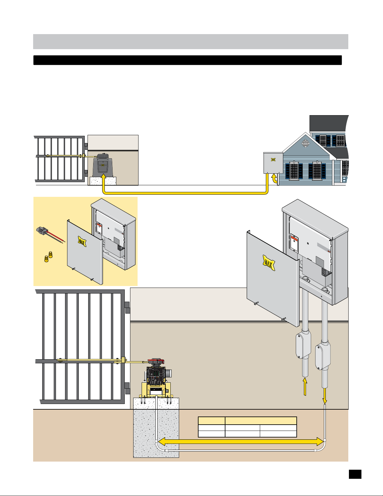
optional remote power supply kit - max magic box
A remote power supply is for installations where it is too costly or difficult to trench a 115/230 VAC power line to the operator
but instead run a low voltage power line to the operator. A MAX Magic Box Kit (sold separately) is required to remotely install a
Remote MAX Megatron Toroid box.
Install the MAX Magic Box near the 115 VAC or 230 VAC input AC power source, up to 1000 ft away from gate operator.
NOTE: A MAX Magic Box kit is required for EACH gate operator when using dual gate operators.
Operator
MAX Magic Box
Near Power Source
MAX Magic Box Kit
Sold Separately
Power/Solar In
Connector
Wire
Nuts
Cove
r
Cabinet
PLY
4
UP
S
-2
S
R
E
P
W
X
O
P
A
M
Remote Toroid
15 Amp Bo
WA
RNING
!
x
H
IGH
VO
LT
AG
d
i
s
c
po
o
E
n
w
ne
e
s
c
r
e
t
b
r
v
ef
ic
o
in
r
e
g
u
n
i
t
Distance - See table below
115/230 VAC Power Source
2-Wires, 24VDC Low Voltage Power
SA
U
in
e
d
a
M
MP
A
E
S
7
U
F
F
R
E
OF
W
O
N
P
O
N
I
C
A
S
elec
t Input V
1
15
VA
C
230V
or
ol
t
230VA
a
ge:
C
warranty
VOID
if la
ED
b
R
el is
E
MOVED
At MAX Magic Box
See page 20 for
MAX Magic Box
wiring instructions.
not suppl
At Gate
Operator
PRIMARY
BATTERY
MATRIX 1
GATE
BACK-UP MODE
LEAVE
MAGLOCK
CLOSED
DELAY
OPEN
OPEN
LEAVE
OPEN
MADE in USA
MAG
RIGHT
LEFT
OPEN
1 TIME
OFF
2Sec1.5Sec
LOCK
COM
NC
AUTOMATIC OPEN/CLOSE CONTROLS
Tamper NO
ANTI
GATE
SAFETYCENTEREXIT
TAILGATE
COM
TAMPER
GND
BOARD
EXIT
OFFON
Tamper IN
MATRIX
CENTER
RS-485 (+) -
PHOTOCELL
RS-485 (-) -
PWR 24V -
UL
EDGE 1
SAFETY
MIN
MAX
OFF
ENTRAP
EDGE 2
GND -
CLOSE TIMER
ID PLUG
PARTIAL
MOTOR MOTION
ERROR
OPEN
ID
INPUTS
PACK
SWITCH
Power In
MOTOR
MOTOR
PLUG
BATTERY
LIMIT
ALARM
UL ALARM 12V
ALARM RET
RESET
OPEN
STOP CLOSE
POSITION
GND
RECORDER
REVERSE SENSITIVITY
MAX
12VDC
GATE SPEED
MOTOR OVERLOAD
GND
OBD PORT
OPEN
BLACK BOX
GATE
MIN
NO LIMIT SWITCH /
COM
STATUS
24VDC
CLAMP SLIPPING
MAX
CLOSE
GND
LIMIT
BATTERY
SWITCH
ON-LINE
IN USE
MOTOR
ON-LINE
POWER
PRIMARY
SEC
GATE
GATE
24V
GND
PHOTOCELL
GND
STRIKE
GND
KEYPAD / RDR
GND
FIRE DEPT
GND
MAX OPEN
GND
RADIO SIG.
RADIO GND
OPEN
STOP
CLOSE
COM
GATE DISABLE
(+)
GND
(-)
(+)
GND
(-)
MAX BC-7
Battery Voltage
Battery Module
EF1/2
ON/OFF
Replace
TEST
Battery IN
Battery
Battery
Battery
Error
Conduit
ied
Inpu
Y
PPL
SU
R
WE
O
P
MAX PS-24
Remote T
15 Amp Bo
VO
oroid
W
A
R
NI
N
G
!
HI
GH
LT
A
di
s
G
co
p
E
o
n
w
n
e
e
se
ct
r
b
rv
e
i
f
c
o
in
r
e
g
unit
tage
l
High
Vo
Input Power
t AC
Power
SA
U
n
i
e
d
a
M
MP
A
E
S
7
U
F
R
FF
O
WE
N
PO
O
N
I
C
A
x
Se
lect
1
In
1
5
p
V
u
AC
t
V
230V
or 23
olt
a
ge:
0V
A
C
w
a
rr
V
anty
OIDED
if
la
be
RE
l
MO
i
s
V
ED
ator
r
tage
l
Low
Vo
Ope
4 VDC
2
To
24VDC
Lo
w
Vo
ltag
Power
e
Ground Level
Conduit
Concrete Pad
Gate Weight Max Wire Distance - Wire Gauge
1400 lbs
2200 lbs
500 ft - 12AWG
500 ft - 10AWG
1000 ft - 10AWG
1000 ft - 8AWG
24VDC Low Voltage Power
11
installation
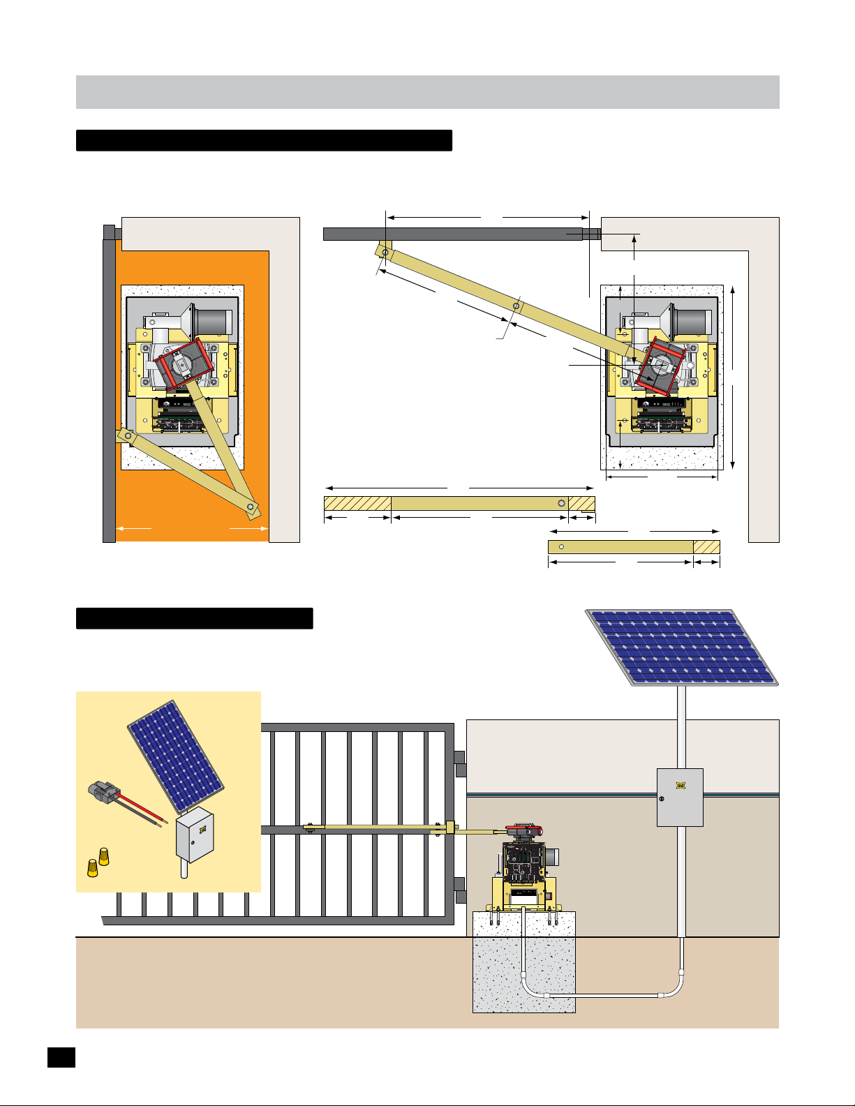
compact installation only
Use compact installation arm measurements when area between the OPEN gate and wall is 20”min to 32”.
DO NOT use these arm measurements for a standard installation. (For standard installation, see page 6)
Gate Bracket Pivot Point
33”
Open Position
Hinge Pivot Point
Closed Position
Illustrations not to scale
LIMIT
LIMIT
CLOSED
OPEN
ERD
MC-200
JOG
Sensitivity
JOG
Motor Controller
Motor
GND
Cell
MATRIX
Photo
LEFT
RIGHT
Jog LT
Edge 1
Edge 2
ON-LINE
UL Entrap
Edge
OverLoad
Jog RT
5
4
1
3
POWER
MAX
2
ERD
12
16
LED ON
Edge
PhotoCell
Limit SW
13
15
14
POWER
POWER/SOLAR
IN
IN
TO MOTOR
CONTROLLER
BATTERY
BATTERY
BATTERY
MATRIX 1
PRIMARY
BACK-UP MODE
GATE
LEAVE
MAGLOCK
CLOSED
DELAY
OPEN
OPEN
PACK
IN
LEAVE
OPEN
MADE in USA
MAG
RIGHT
LEFT
OPEN
1 TIME
OFF
2Sec1.5Sec
LOCK
COM
NC
AUTOMATIC OPEN/CLOSE CONTROLS
Tamper NO
ANTI
GATE
SAFETYCENTEREXIT
TAILGATE
COM
TAMPER
GND
EXIT
OFFON
Tamper IN
CENTER
PHOTOCELL
UL
EDGE 1
SAFETY
MIN
MAX
OFF
ENTRAP
EDGE 2
CLOSE TIMER
ID PLUG
PARTIAL
MOTOR MOTION
ERROR
OPEN
ID
PLUG
UL ALARM 12V
ALARM RET
RESET
OPEN
STOPCLOSE
GND
POSITION
RECORDER
REVERSE SENSITIVITY
MAX
12VDC
GATE SPEED
MOTOR OVERLOAD
GND
OBD PORT
OPEN
BLACK BOX
GATE
MIN
NO LIMIT SWITCH /
COM
STATUS
CLAMP SLIPPING
24VDC
MAX
CLOSE
GND
LIMIT
BATTERY
SWITCH
ON-LINE
IN USE
MOTOR
ON-LINE
POWER
PRIMARY
SEC
GATE
GATE
24V
GND
PHOTOCELL
GND
STRIKE
GND
KEYPAD / RDR
GND
FIRE DEPT
GND
MAX OPEN
GND
RADIO SIG.
RADIO GND
OPEN
STOP
CLOSE
COM
GATE DISABLE
(+)
GND
(-)
(+)
GND
(-)
www.max.us.com
Made in USA
Wall
Entrapment Area
20”min to 32”
It is necessary to protect against the entrapment
that could occur with this type of installation.
(See entrapment protection on page 13)
solar - Optional
Refer to Solar application guide.
MAX Solar Power Kit: MUST be used
when using solar power. Sold separately.
MAX
Solar Panel
24 Volt
Solar
Power
Kit
Long Arm
23”
Arm Elbow Pivot Point
25.5”
Operator Pivot Point
Cut the standard arms down to
meet the shorter measurements.
36”
Long ArmCut Cut
10” 22”
Solar Panel: must be mounted facing
south. It must get full sunlight throughout
the day, NO shadow obstructions.
Short Arm
26.5”
8”
8”
4”
Short Arm
20”
24”
Motor
OverLoad
ERD
12
MATRIX 1
MADE in USA
AUTOMATIC OPEN/CLOSE CONTROLS
EXIT
CENTER
SAFETY
ID
PLUG
12VDC
GND
24VDC
GND
RADIO SIG.
RADIO GND
ERD
JOG
Sensitivity
JOG
LEFT
RIGHT
5
4
3
MAX
16
LED ON
13
15
14
POWER/SOLAR
IN
BATTERY
BATTERY
BACK-UP MODE
LEAVE
CLOSED
IN
LEAVE
OPEN
OPEN
1 TIME
ANTI
TAILGATE
OFFON
MIN
MAX
OFF
CLOSE TIMER
PARTIAL
OPEN
POSITION
RECORDER
MAX
GATE SPEED
OBD PORT
BLACK BOX
MIN
MAX
PHOTOCELL
STRIKE
GND
KEYPAD / RDR
GND
FIRE DEPT
GND
MAX OPEN
GND
www.max.us.com
18.3”
LIMIT
LIMIT
CLOSED
OPEN
GND
Cell
MATRIX
Photo
Jog LT
Edge 1
Edge 2
ON-LINE
UL Entrap
Edge
Jog RT
1
2
Edge
PhotoCell
Limit SW
POWER
IN
TO MOTOR
CONTROLLER
BATTERY
PRIMARY
GATE
MAGLOCK
DELAY
OPEN
OPEN
PACK
MAG
RIGHT
LEFT
OFF
2Sec1.5Sec
LOCK
GATE
SAFETYCENTEREXIT
TAMPER
UL
ENTRAP
MOTOR MOTION
UL ALARM 12V
OPEN
STOPCLOSE
REVERSE SENSITIVITY
MOTOR OVERLOAD
GATE
NO LIMIT SWITCH /
STATUS
CLAMP SLIPPING
LIMIT
SWITCH
ON-LINE
MOTOR
ON-LINE
PRIMARY
SEC
GATE
GATE
GND
OPEN
STOP
CLOSE
COM
GATE DISABLE
(+)
GND
(-)
(+)
GND
(-)
Made in USA
MC-200
Motor Controller
POWER
COM
NC
Tamper NO
COM
GND
Tamper IN
PHOTOCELL
EDGE 1
EDGE 2
ID PLUG
ERROR
ALARM RET
RESET
GND
OPEN
COM
CLOSE
BATTERY
IN USE
POWER
24V
GND
Cut
MAX Solar Kit
30”
4”
12
Power/Solar
Connector
Wire
Nuts
In
PRIMARY
BATTERY
MATRIX 1
GATE
BACK-UP MODE
LEAVE
MAGLOCK
CLOSED
DELAY
OPEN
OPEN
LEAVE
OPEN
MADE in USA
MAG
RIGHT
LEFT
OPEN
1 TIME
OFF
2Sec1.5Sec
LOCK
COM
NC
AUTOMATIC OPEN/CLOSE CONTROLS
Tamper NO
ANTI
GATE
SAFETYCENTEREXIT
TAILGATE
COM
TAMPER
GND
BOARD
EXIT
OFFON
Tamper IN
MATRIX
CENTER
RS-485 (+) -
PHOTOCELL
RS-485 (-) -
PWR 24V -
UL
EDGE 1
SAFETY
MIN
MAX
OFF
ENTRAP
EDGE 2
GND -
CLOSE TIMER
ID PLUG
PARTIAL
MOTOR MOTION
ERROR
s
Solar Panel
Electronic
Box
OPEN
ID
INPUTS
PACK
SWITCH
Power In
MOTOR
MOTOR
PLUG
BATTERY
ALARM
LIMIT
UL ALARM 12V
ALARM RET
RESET
OPEN
STOP CLOSE
POSITION
GND
RECORDER
REVERSE SENSITIVITY
MAX
12VDC
GATE SPEED
MOTOR OVERLOAD
GND
OBD PORT
OPEN
BLACK BOX
GATE
MIN
NO LIMIT SWITCH /
COM
STATUS
24VDC
CLAMP SLIPPING
MAX
CLOSE
GND
LIMIT
BATTERY
SWITCH
ON-LINE
IN USE
MOTOR
ON-LINE
POWER
PRIMARY
SEC
GATE
GATE
24V
GND
PHOTOCELL
GND
STRIKE
GND
KEYPAD / RDR
GND
FIRE DEPT
GND
MAX OPEN
GND
RADIO SIG.
RADIO GND
OPEN
STOP
CLOSE
COM
GATE DISABLE
(+)
GND
(-)
(+)
GND
(-)
MAX BC-7
Battery Voltage
Battery Module
EF1/2
ON/OFF
Replace
TEST
Battery IN
Battery
Battery
Battery
Error
Solar Panel
Electronics
Box
installation
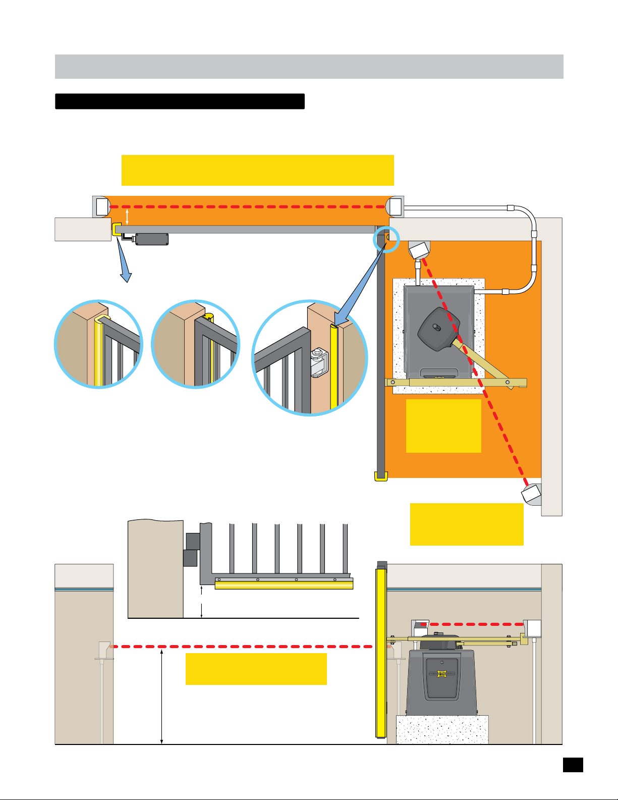
entrapment protection
Install photocells and/or sensing edges to help protect against entrapment during cycling of the gate (entrapment protection).
ONE entrapment protection sensor MUST be installed and connected to “Edge 1 CLOSING direction” on MC-200 motor
controller or operator will NOT function. Entrapment protection sensors MUST be MONITORED and NORMALLY CLOSED (N.C.).
IMPORTANT: Sensing edges MUST be Monitored 10K Normally
Closed Type and a GEM-104 module MUST be installed.
Top View
CLOSING direction photocell to
MC-200 EDGE 1 input, Monitored.
Normally CLOSED (N.C.)
Beam: 5” or LESS from CLOSED gate.
Wireless
WIRELESS NOTE: Refer to the instruction sheet that
Module
comes with the wireless module for wiring and
mounting instructions when using wireless option.
Cl
osed Gate
OPENING/CLOSING
Two Sided 10K Sensing Edge
to Edge 2 or Photo Cell input
MC-200 Edge 2 or Photo Cell input
CLOSING ONLY
10K Sensing Edge
MC-200 Edge 1 input
Closed Gate
One Sided
See pages 17-18 for wiring
instructions.
Dual Gate Operators NOTE: Run EACH entrapment
protection sensor to each corresponding GATE
OPERATOR’S MC-200 motor controller. See page 9.
Entrapment Area
Gate Closed
Hinge AreaEnd of Gate Options
Closed Gate
The hinge area may need protection
against entrapment. MAX 10K mini
sensing edge works well in this area.
(OPEN/CLOSE direction, MC-200
Edge 2 or Photo Cell input)
Bottom of Gate
Conduit
Gate Open
OPENING/CLOSING or
Closing ONLY 10K (N.C.)
Sensing Edge
Max 10K Mini Sensing Edge (N.C.)
Area
Entrapment
IMPORTANT:
Photocells MUST
be in alignment
or fault will occur.
Normally CLOSED (N.C.)
OPENING direction Photocell
IMPORTANT: Photocells
MUST be Monitored
Normally Closed Type.
Side View
6” or More
CLOSING direction Photocell
IMPORTANT: Photocells MUST
Beam Height:
21” Normal
27.5” Max.
be in alignment or fault will occur.
OPEN/CLOSE Sensing Edge on Bottom of Gate: If
the bottom of gate is 6” or higher above the ground,
then a 10K sensing edge should be installed.
Entrapment Protection
10K Sensing Edge,
Install along entire
edge of gate.
OPENING direction Photocell,
Install just above gate operator.
Gate Open
13
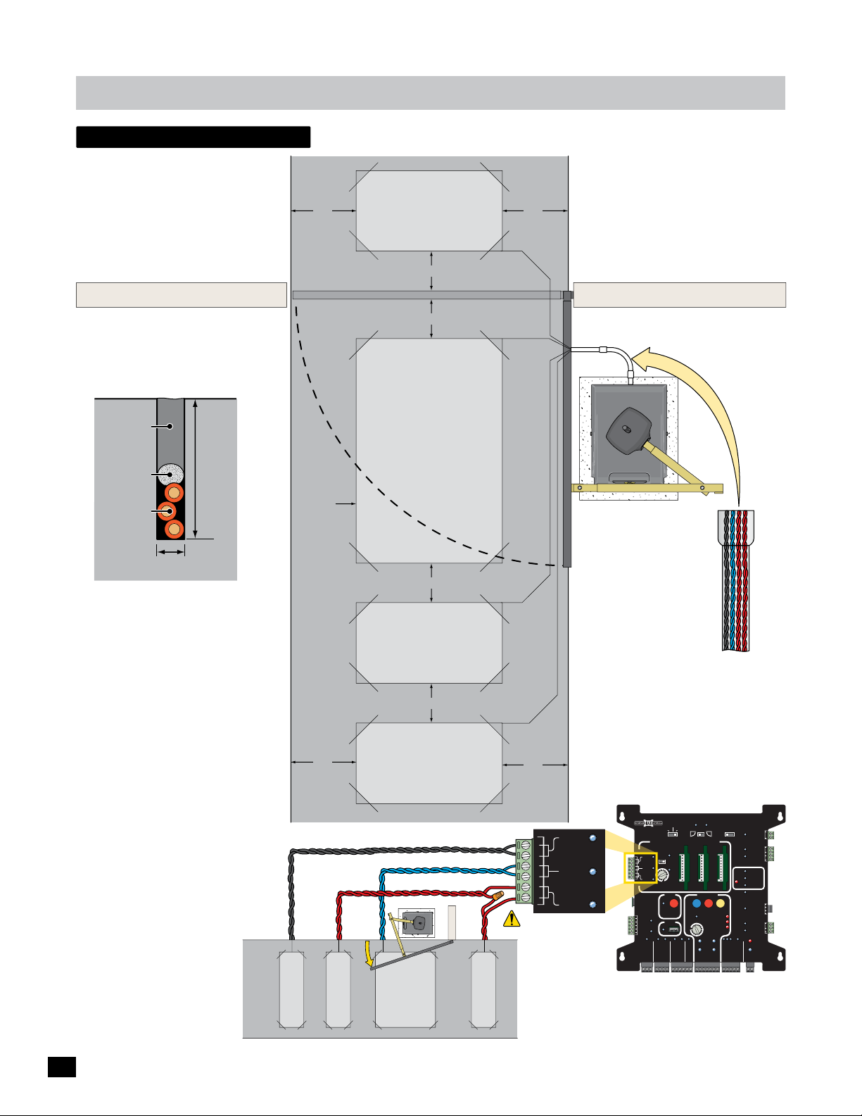
in-ground loops
T
Install in-ground loops to help
protect vehicles from a moving
gate. See pages 25 & 29 for
wiring instructions.
Outside Property
Illustration not to scale
installation
4 ft
Safety
Loop
4 ft
4 ft
Refer to loop maunufacturer’s
instructions to determine specific
loop dimensions.
It is recommended that a
licenced installer perform
this work.
Inside Property
Side View of
Saw Cut
Sealant
Backer Rod
Loop Wire
1/4” Saw Cut
Pavement
Safety Loops
Are placed on each side of the gate to prevent
the gate from closing on a vehicle in it’s path.
They will stop or reverse the cycling of the
gate while a vehicle is in or near the gate’s
pathway.
Center Loop
Will ONLY HOLD the gate in the Full Open
Position when a vehicle is on the center loop.
However, it WILL NOT stop or reverse the
gate once it starts to close.
Exit Loop
Automatically opens the gate for exiting
vehicles without having to use a radio
transmitter (remote control). The exit loop
can be placed a minimum of 4 feet away from
the safety loop or far enough away from the
gate so it has opened by the time the vehicle
approaches it.
1 1/2”
Typical
Inside Property
Saw Cut
4 ft
EXIT LOOP
Lead Wires
SAFETY LOOP
4 ft
Center
Loop
4 ft
Safety
Loop
4 ft min.
Exit
Loop
CENTER LOOP
4 ft
Safety loops need
to be wired in series.
Outside Property
SAFETY LOOP
Lead Wires
Lead Wires
EXIT
CENTER
SAFETY
Conduit
Loop lead wires are
twisted 6 twists per
foot minimum inside
conduit.
Matrix 1 Wiring
BATTERY
MATRIX 1
MADE in USA
AUTOMATIC OPEN/CLOSE CONTROLS
EXIT
CENTER
SAFETY
ID
PLUG
12VDC
GND
24VDC
GND
RADIO SIG.
RADIO GND
ANTI
TAILGATE
MIN
CLOSE TIMER
FIRE DEPT
BACK-UP MODE
LEAVE
OPEN
OFFON
MAX
OFF
POSITION
RECORDER
OBD PORT
BLACK BOX
GND
MAX OPEN
PRIMARY
GATE
LEAVE
CLOSED
OPEN
OPEN
OPEN
RIGHT
LEFT
1 TIME
SAFETYCENTEREXIT
PARTIAL
MOTOR MOTION
OPEN
OPEN
STOP CLOSE
REVERSE SENSITIVITY
MAX
GATE SPEED
MOTOR OVERLOAD
MIN
NO LIMIT SWITCH /
CLAMP SLIPPING
MAX
LIMIT
SWITCH
ON-LINE
MOTOR
ON-LINE
PRIMARY
SEC
GATE
GATE
PHOTOCELL
GND
STRIKE
GND
KEYPAD / RDR
GND
GND
(+)
GND
(-)
(+)
GND
(-)
MAGLOCK
DELAY
MAG
OFF
2Sec1.5Sec
LOCK
COM
NC
Tamper NO
GATE
COM
TAMPER
GND
Tamper IN
PHOTOCELL
UL
EDGE 1
ENTRAP
EDGE 2
ID PLUG
ERROR
UL ALARM 12V
ALARM RET
RESET
GND
OPEN
GATE
COM
STATUS
CLOSE
BATTERY
IN USE
POWER
24V
GND
OPEN
STOP
CLOSE
COM
GATE DISABLE
14
 Loading...