

Page 1
Quick Install Guide for
MAX 1500 / MAX 2200
Slide Gate Operators
CONFORMS TO UL STD 325
UL CLASS - I, II, III, IV
CERTIFIED TO CAN/CSA STD
C22.2 NO. 247
SAFETY SENSORS REQUIRED
Version 8
Residential/Commercial
Brushless DC Slide Gate Operators
Made in USA
www.max.us.com
1
4009963
UL 325 2016 Standard-MAX Quick Install Rev 8
Page 2
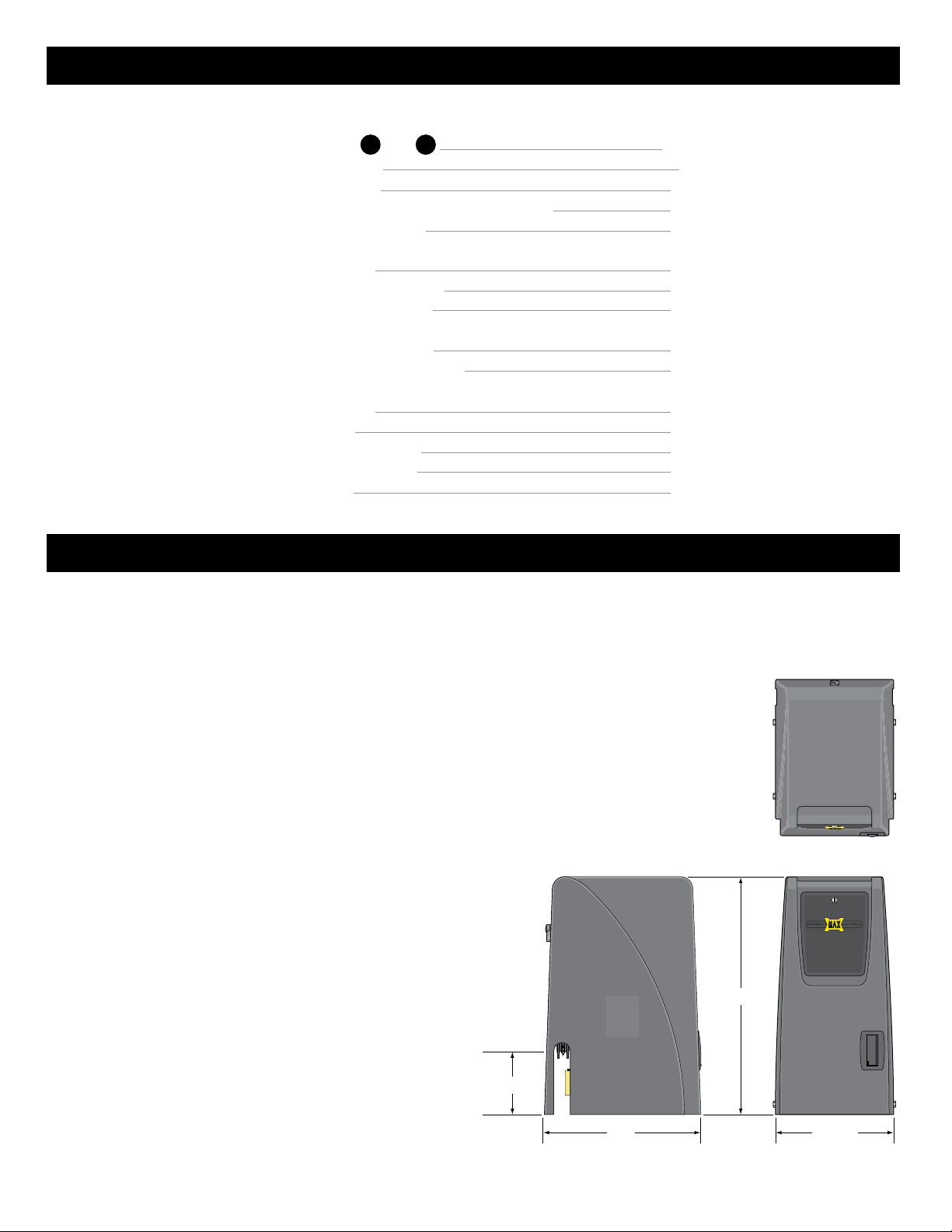
Table of Contents
Quick Install Guide
Installation Steps 1 thru 12
1 12
Gate Shut-Off Switch
Gate Tamper Feature
Dropping the Chain - Gate Tamper is Armed (ON)
Dual Gate Operators Wiring
Page
1-10
11
12
13
14
Troubleshooting
USB Black Box Port
Test Edge 1 Entrapment sensor
Gate Cycling Troubleshooting
Matrix 1 LED Troubleshooting
MC-200 LED Troubleshooting
BC-7 Module LED Troubleshooting
15
15
16
17-18
19
20
Commonly Used Safety Sensor Wiring
Omron E3K-R10K4
Omron IRB-RET
EMX IRB-MON Single Gate
EMX IRB-MON Dual Gates
Miller Gate Link
21
21
22
23
24
MAX 1500 / 2200 specifications
UL 325 Class of Operation - Class I, II, III, IV
Gate Type - Vehicular Slide Gate
Max Gate Length - 50 ft
Max Gate Weight:
• MAX 1500 - 1500 lbs Level Gate; 1000 lbs Uphill Gate - 5° Max
• MAX 2200 - 2200 lbs Level Gate; 1500 lbs Uphill Gate - 5° Max
Opening Time - Selectable speed control (MAX - 12 inch per second)
Cycles per Hour AC Power - Continuous
Battery Back-Up Cycles (Batteries fully charged):
• MAX 1500 - approximately 100 cycles
• MAX 2200 - approximately 100 cycles
NOTE: The number of gate cycles using ONLY battery back-up power will vary
depending on the weight of the gate, the gate length, the operating condition
of the gate, temperature and the amount of charge the batteries have at the
beginning of the battery power only operation.
Input AC Power/Amps - Switchable: 115VAC / 6 Amp, 1 phase
or 230VAC / 2 Amp, 1 phase
Motor:
• MAX 1500 - 1/2 HP 24VDC Brushless (6 million cycles)
• MAX 2200 - 1 HP 24VDC Brushless (6 million cycles)
Chain Size - #40
Operating Temperature: -4°F to 158°F (-20°C to 70°C)
Entrapment Protection:
- UL 325 Type A Inherent (ERD sensor)
- Inputs for NORMALLY CLOSED (N.C.)
UL 325 Type B1 (photo cell)
and Type B2 (sensing edge)
2
29”
7 1/2”
14 1/2”19”
UL 325 2016 Standard-MAX Quick Install Rev 8
Page 3
Quick Install Guide
www.max.us.com
For detailed installation instructions and COMPLETE information about ALL the available options & features for
the MAX 1500/2200/F18, please refer to the MAX 1500/2200/F18 Installation and Owners manuals.
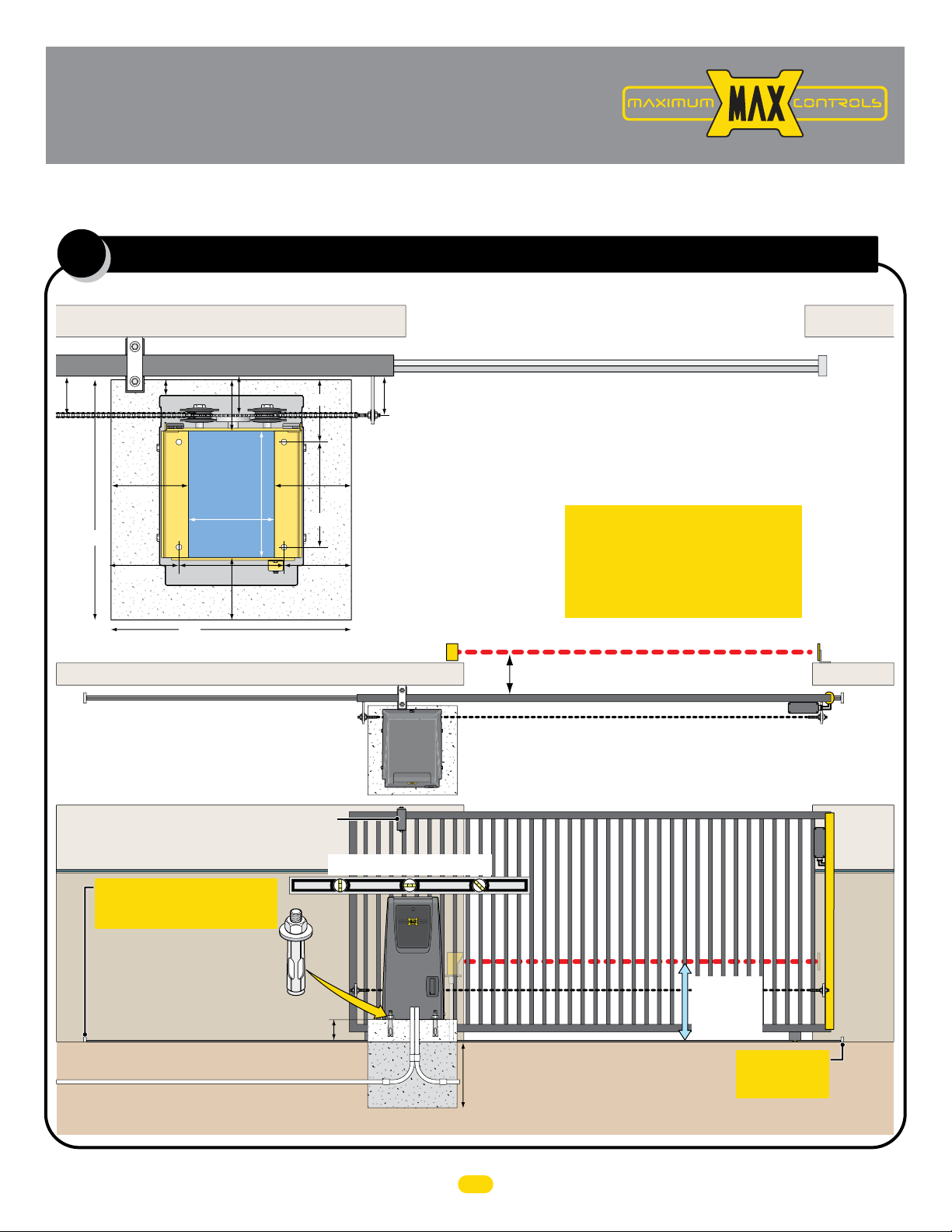
Operator Placement (standard)
1
The gate must be properly installed and work freely in both directions prior to installation of the gate operator.
Guide Rollers
24”
6.75”
Outside Property
1.5”
24”
Conduit
8.625”
10.5”
12.75”
Area
2” Gate Frame
4”5”
Cover
6.5”
6.2”
7.5”7.5”
10.5”
6.75”
Concrete Pad
Photcell to MC-200 EDGE 1 Input
4”4”
Operator
Position on
Concrete Pad
V-Rail
Conduit Guidelines and Suggestions
• REQUIRED - AC input power wire.
• REQUIRED - Entrapment protection CLOSING photocell and/or
sensing edge - when not using Gate Link wireless transmitter.
• In-ground loop wires.
UL 325 2016 Standard
ONE Entrapment protection sensor
MUST installed or operator will NOT
function. It MUST be MONITORED
and NORMALLY CLOSED (N.C.).
CLOSING Photocell Beam can be 5” or less away from gate
Physical Stop
Reflector
Gate in Closed Position
Inside Property
Operator in Front Position (Standard)
Note: See manual when mounting operator in REAR Position.
Guide rollers MUST be Installed to keep gate upright.
Operator MUST be level.
IMPORTANT: Physical stops MUST
be installed on BOTH ends of rail to
keep gate from traveling off of rail.
Secure gate operator to
concrete pad with four
(4) 1/2” x 3” (min)
sleeve anchors.
6” above ground to avoid flooding.
Input Power
Concrete Depth Note: The heavier the gate, the deeper the concrete pad should be. At least two feet recommended for heavier gate.
1/2
Conduit Run
Concrete Pad
Check local building
codes in your area for
depth of concrete
before installation.
Photocell
Beam Height:
21” Normal
27.5” Max.
MUST be installed
Wireless
Module
IMPORTANT:
Physical Stop
CLOSING
Sensing
Edge with
Wireless
Module
Wireless
Module
CLOSING
Sensing
Edge with
Wireless
Module
UL 325 2016 Standard-MAX Quick Install Rev 8
1
Page 4
2
YES
NO
YES
YES
NO
NO
NO
NO
NO
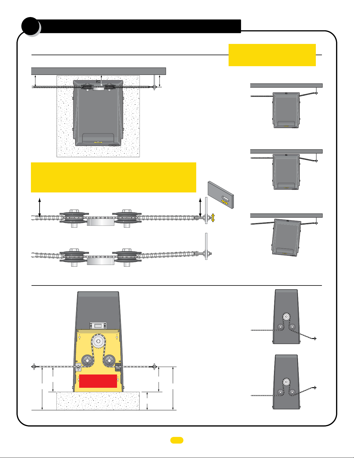
connect chain to gate
Top View of Operator
NOTE: 25 ft of #40 nickel plated chain included.
Minimum distance between the drive gear and gate is 4”.
4” Min4” Min
Drive
Gear
Chain
Bracket
YES
IMPORTANT: Operator and chain MUST be parallel to gate or the idler
wheels could fail. Use the “Fine Tune” adjustment on the gate bracket
connection bolt and make sure the chain runs through the idler wheels
without binding on the side chain guides.
YES
Side Chain Guide
Side Chain Guide
Idler Wheel
4” Min4” Min
NO
Gate Bracket
Fine Tune
Adjustment
IMPORTANT: Physical stops MUST be
installed on BOTH ends of gate rail to
keep gate from traveling off of rail.
NO
Operator is too far from gate.
Chain is NOT parallel to gate.
NO
Operator is too close to gate.
Chain is NOT parallel to gate.
NO
Operator is NOT parallel to gate.
Chain is NOT parallel to gate.
Back View of Operator
YES
Chain brackets MUST
remain same height as
idler wheels.
Chain
Bracket
Idler Wheels
Factory installed
position
Concrete Pad
Operator in Front Position (Standard)
Chain
Bracket
7.5”7.5”
6”
Note: See manual when Connecting chain
with operator mounted in REAR Position.
NOTE: The chain should
sag no more than one (1)
inch per 10 feet of travel.
Do not over tighten the
chain.
13.5”13.5”
2
NO
Chain
Bracket
DO NOT mount chain bracket too low on gate.
NO
Chain
Bracket
DO NOT mount chain
bracket too high on gate.
UL 325 2016 Standard-MAX Quick Install Rev 8
Page 5
ac input power
W
A
RN
IN
G
HIGH
V
O
L
T
AG
E
A
T
T
E
NT
ION!
H
I
G
H
VO
LT
A
G
E
W
ARNING
HIGH
V
O
LT
A
G
E
3
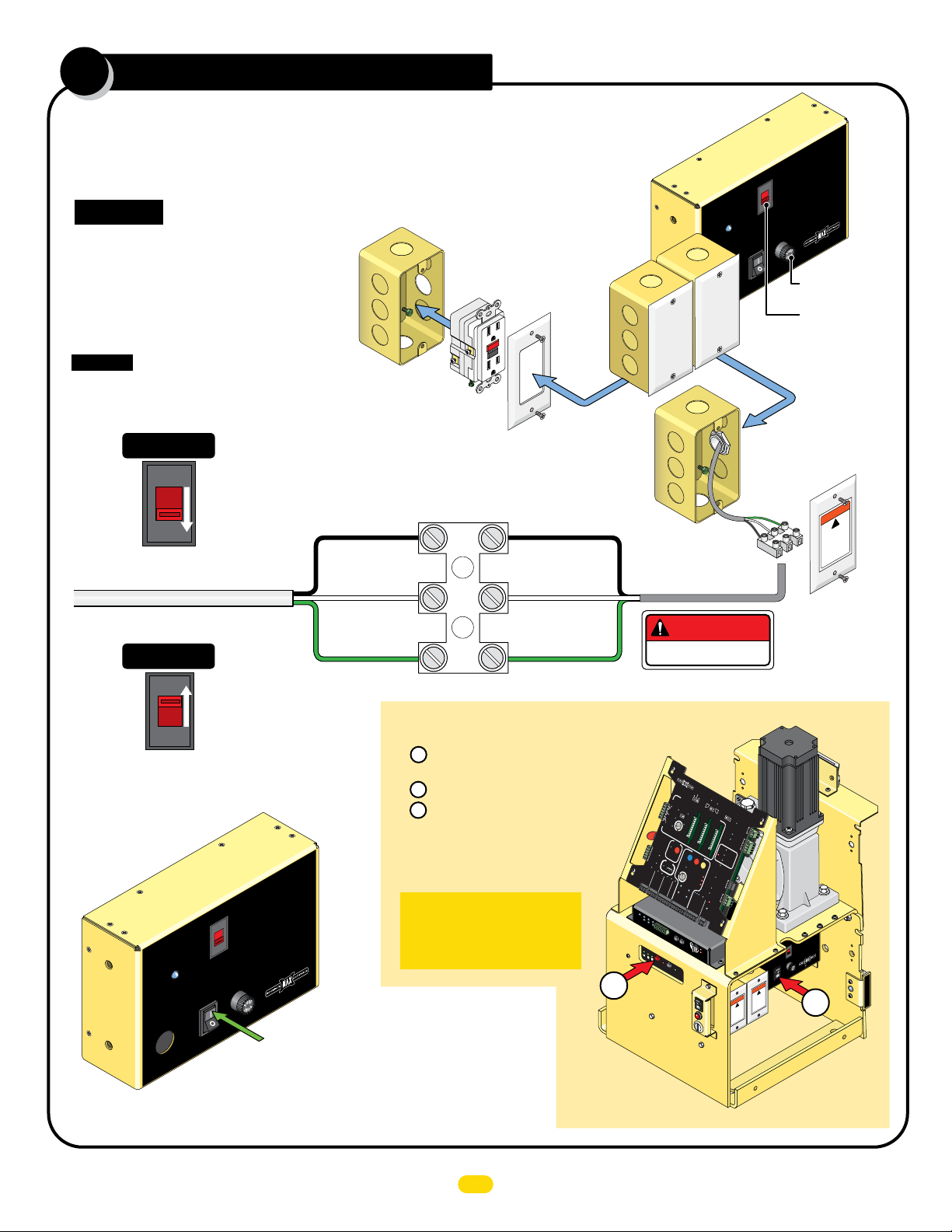
Choose either 115V or 230V setting on input AC power selector switch.
Wire desired input AC power wire to power terminal. A additional single gang box is provided to
install power outlets if desired. GFCI outlet type is recommended.
CAUTION: Make sure circuit
breaker is OFF from incoming
AC input wire BEFORE wiring!
Additional single gang box
provided. Wire GFCI outlet
to the input AC wire
BEFORE connecting to
operator power terminal if
power outlets are desired.
Input AC Power Options
CAUTION: If input AC power selector
switch is set for 115V but input power
is actually 230 V, 7 Amp Fuse will blow.
Single Phase 115VAC Only
115VAC
115V
Set to 115V
115 OR 230VAC
Power Wire
Single Phase 230VAC Only
230VAC
IMPORTANT: Make sure there are NO exposed bare
wires at the power terminal connection.
Chassis (Green)
Additional
Gang Box
Line (Black)
Neutral (White)
GFCI Outlet
NOT provided
Power Terminal
Line (Black)
Neutral (White)
Chassis (Green)
MAX
Toroid Box
AC
IN
Additional
AC
Power
Bo
Box
x
DANGER
HIGH VOLTAGE!
11
5
V
ER
OW
P
On
To
Off
AX
M
AC Power
Gang Box
Power
Terminal
Input
t
Selec
tage
Vol
AC or
5V
AC
11
230V
www.Max.US.com
FUSE
Amp
7
roid 15 Amp
7 Amp Fuse
Input AC Power
Selector Switch
WARNING
!
HIGH
LT
VO
sconn
di
power
icing unit
v
ser
E
AG
t
ec
before
Set to 230V
230V
Turn Power
ON
MAX
Toroid Box
AC
N
I
LEDs should light up on operator.
Battery power automatically turns ON.
Turn ALL Power OFF
1 Turn OFF POWER Switch on MAX Toroid Box.
Battery power will remain ON.
2 WAIT for 15 seconds.
3 Press and HOLD (approx. 5 seconds)
the RED ON/OFF BATTERY button until
MAX BC-7 LEDs turn ON,
then release button. LEDs will
turn OFF. (Up to 30 sec.)
t
pu
n
lect I
e
Se
g
or
Volta
AC
115V
5V
C
11
230VA
om
c
S.
.U
x
Ma
www.
FUSE
OWER
P
p
p
Am
7
MAX Toro
id 15
Am
n
O
Off
Turn Power ON
IMPORTANT: This procedure
must be followed whenever
ALL power must be turned
OFF on operator.
DO NOT
CYCLE
MC
Mo
3
OPERATOR!
3
MA
T
R
I
X
1
MA
B
AT
D
BACK-
E
i
T
n
E
USA
RY
U
P
M
ODE
LE
LE
AV
A
C
E
V
LO
E
O
SE
P
EN
D
P
RIM
OP
A
R
EN
G
Y
1
AT
A
TI
M
UT
E
E
OM
OP
EN
A
L
E
TI
F
T
C
OP
OP
AN
EN
R
EX
I
T
GH
TA
I
I
T
EN
T
IL
GA
M
/
AG
TE
C
L
L
O
OSE
O
CE
NT
E
R
SA
F
ET
Y
M
I
N
O
M
F
A
F
X
C
L
O
S
E
T
IME
ID
R
P
L
U
G
PA
RT
I
AL
O
P
E
N
12
V
D
C
G
N
D
P
O
SI
R
T
I
E
O
CO
24
N
V
R
D
C
DE
R
G
N
D
OBD
P
B
ORT
L
A
C
K
MAX
B
OX
G
M
IN
M
A
X
D
EPT
D
RADIO SIG.
R
RADIO GN
RE
D
I
F
E
L
/ RD
AX OPEN
D
GN
M
RIK
GN
D
PAD
Y
ST
M
GN
O
KE
P
N
R
I
GND
M
A
RY
GA
PHOTOCEL
T
E
GND
)
D
(+
GN
(-)
P
h
ot
oCe
P
OW
l
l
E
d
g
ER
e
Li
mi
t
-2
SW
2
00
t
o
UL
r
C
E
n
1
o
t
Ed
ra
n
p
t
g
ro
e
l
l
MA
e
r
TR
ON
I
X
-
L
I
NE
Cell
Photo
Edge 2
Edge 1
Jog RT
GND
Jog LT
J
OG
L
E
F
J
T
RI
E
1/
2
F
O
N
/O
F
Ba
F
Battery
t
Re
te
ry
pl
a
c
Ba
M
e
o
tt
d
e
u
ry
l
TEST
e
Ba
tte
PWR IN
ry
E
rro
r
D
N
OF
F
O
AT
E
SPE
LIMIT
SW
IT
O
C
N
L
INE
O
TO
R
LIN
E
SE
C
G
ATE
D
+)
(
GN
-)
(
MAX
LE
OG
GH
T
CK
E
OF
L
A
E
F
Y
X
C
IT
1.
ONTROL
5S
e
c
2S
e
c
MA
CEN
G
S
T
LO
E
R
CK
SAF
E
CO
TY
M
N
C
G
AT
E
TA
M
T
a
PE
m
p
R
e
r
N
O
CO
M
G
T
N
a
D
m
p
e
r
IN
PH
UL
MO
O
T
OCEL
T
O
R
MO
L
T
E
I
NT
O
N
R
E
AP
D
G
E
1
P
E
E
D
N
G
E
2
S
T
O
PCL
ID
PL
U
RE
G
E
O
VE
RROR
S
R
E
E
S
E
D
S
E
N
SITI
U
M
L
VI
OT
AL
T
O
Y
R
A
O
R
VER
ALAR
M
1
L
NO
O
2
A
LI
D
V
M
M
M
C
I
R
T
LAMP
OTOR
S
E
W
T
R
I
TC
E
S
S
LI
H
E
PP
/
T
I
NG
G
N
D
GAT
P
E
ower
S
T
A
H
TU
In
S
M
O
OT
I
P
N
OR
E
P
N
U
TS
C
O
B
A
M
T
T
CL
P
ER
A
C
OSE
Y
K
L
IM
S
W
IT
I
TCH
E
BA
A
L
T
A
T
R
E
M
R
Y
E
P
IN
U
SE
OPEN
M
STO
CLOS
PO
CO
GATE DISABL
D
O
1
1
5
N
6
14
1
3
1
2
3
4
5
E
R
ER
Se
Mot
D
n
si
Ov
ti
vi
ty
e
r
W
-
)
E
R
+
-
(
)
-
-
(
D
4V
2
GN
D
o
r
L
o
a
d
D
485
-
485
S-
V
GN
4
R
S-
2
R
M
R
A
W
T
B
R
P
O
I
ARD
X
put
t In
Selec
tage
or
l
C
Vo
A
1
1
5
V
5V
m
11
0VAC
.co
23
x.US
a
M
.
w
w
w
SE
U
F
ER
W
AC
O
P
IN
mp
n
p
A
O
7
m
A
5
1
ff
oroid
O
T
X
A
M
G
IN
RN
A
W
!
E
HIGH
N!
AG
O
I
T
t
L
O
e
r
V
TENT
onnec
fo
c
AT
is
it
be
d
un
!
g
in
power
ic
H
v
er
E
s
HIG
AG
T
r
he
nc
VOL
ra
nt
'b
a
en
e
i
t
d
av
e
r
t
n
'e
l
1
L
I
M
I
T
S
E
N
S
O
R
UL 325 2016 Standard-MAX Quick Install Rev 8
Page 6
L
ground operator
WARNING
W
A
RN
I
N
G
4
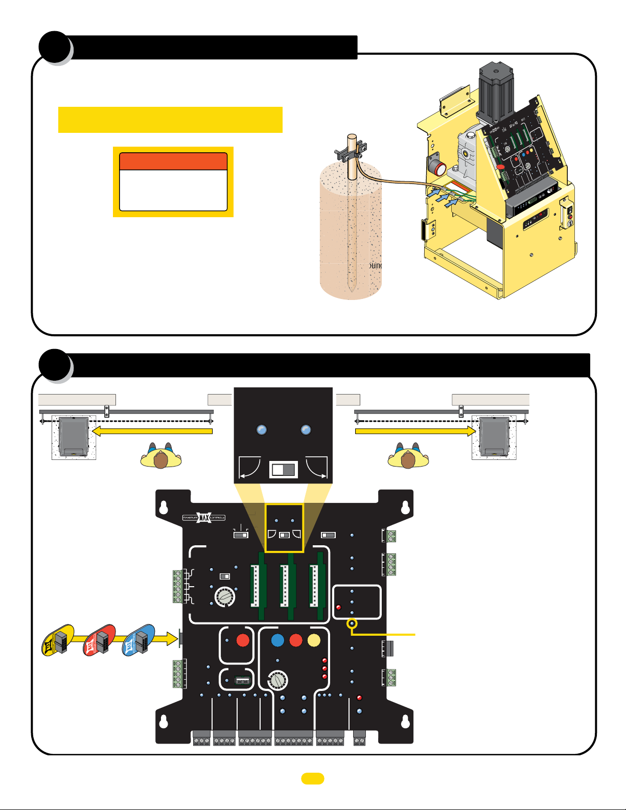
Operator MUST be Properly GROUNDED
IMPORTANT: Operator MUST be grounded in lightning
prone areas or warranty will be VOIDED!
WARNING
connect chassis
to ground rod for
lightning protection
Proper grounding of this gate operator is a requirement for
LIGHTNING PROTECTION in lightning prone areas. To be effective,
ground connections should be made with a minimum 12 AWG, 600
volt insulated wire to a ground point within 3 feet of the gate
operator. The ground point must be at an electrical panel, a
metallic cold water pipe that runs in the earth, or a grounding rod.
Ground
within 3 ft
of operator.
Chassis
Grounding Rod
Ground
M
CO
AG
M
NC
OCK
LOCK
AGL
Y
A
M
ec
L
S
Y
2
DE
c
AR
e
S
5
IM
.
1
E
PR
T
F
F
O
GA
r NO
e
N
p
PE
M
m
T
a
O
T
H
CO
IG
Y
R
N
R
E
E
E
P
GND
O
OD
TT
T
BA
LEF
P M
U
E
V
N
A
E
E
BACK-
D
L
P
E
O
1
S
M
O
I
T
CL
1
IX
TR
A
VE
A
M
E
L
PEN
O
A
US
n
i
E
D
A
M
O
IC
T
A
M
TO
U
A
E
ANTI
T
A
G
TAIL
FF
O
N
O
T
XI
E
R
E
T
EN
C
Y
T
E
F
A
S
ID
G
U
PL
T
T
A
B
R
O
S
T
OT
U
P
M
N
I
n
I
r
e
w
o
WARNING
c
o
t
li
n
o
n
g
g
e
h
r
c
t
o
n
t c
u
in
nd
h
g
a
p
r
s
o
r
s
o
d
i
t
for
s
e
c
t
io
n
1
2
3
L
I
M
I
T
S
E
N
S
O
R
P
R
OTO
M
IN
r
e
ATE
LS
G
amp
T
R
O
E
PE
TR
AM
T
N
O
C
TY
E
E
L
F
S
SA
OCEL
LO
OT
/C
PH
N
E
P
XIT
E
N
I
F
F
M
O
OSE
CL
C
D
V
2
1
D
N
G
LIM
W
S
RY
V
E
4
2
K
C
A
P
G
1
R
E
DG
NTE
E
CE
2
GE
D
E
L
U
G
U
AP
PL
R
T
R
ID
N
O
E
ERR
V
2
1
T
E
ARM
R
AL
M
T
E
AR
UL
ES
AL
R
ND
G
N
O
I
T
O
M
R
O
T
O
M
AX
M
ER
IM
T
AL
I
T
R
N
PA
E
OP
SITIO
PO
ECOR
R
M
R
A
L
A
T
I
H
C
T
I
C
D
D
N
D
.
G
I
S
O
I
D
A
R
P
MC
ot
M
OPEN
SE
COM
O
CL
Y
T
P
CLOSE
I
V
E
O
T
TI
I
ST
S
N
GA
E
S
US
E
D
A
Y
N
RS
O
E
R
L
V
R
E
STAT
E
E
T
R
V
OPE
T
O
R
BA
/
O
T
H
O
C
T
M
IN USE
NG
I
SWI
P
T
P
D
I
L
MI
I
S
EE
L
AX
R
O
M
E
MP
N
SP
A
L
W
E
C
T
N
ER
D
T
OR
P
BD
BO
O
K
BLAC
PT
E
N
D
G
O
I
D
A
R
P
R
E
W
O
0
tr
20
n
-
r Co
o
PO
GA
E
L
-
B
V
N
-
4
MI
2
D
-
D
SA
R
N
)
I
-
G
W
(
-
N
P
V
)
AX
D
+
85
M
X
MIT
(
G
I
4
4
H
L
-
C
S
85
E
2
IT
4
X
R
E
I
-
W
N
T
S
S
R
D
LI
R
M
R
A
SE
AT
A
ON-
M
O
P
G
O
B
N
CO
O
OR
T
E
CL
NE
MO
P
C
LI
ST
-
SE
N
O
O
E
T
A
G
)
D
Y
L
(-
N
R
R
)
L
G
MA
I
R
D
E
E
P
(+
T
A
G
C
)
D
-
/ R
(
O
N
)
T
G
D
+
(
O
N
AD
D
G
PH
N
YP
KE
D
I
G
PEN
N
R
KE
O
T
G
D
S
X
N
A
D
G
E
N
M
R
G
I
F
Li
e
dg
E
ell
2
oC
hot
1
M
N
dge
O
E
L
U
ap
r
t
En
r
e
oll
D
R
E
3
2
1
1
4
1
r
5
o
1
ot
6
d
1
M
a
o
L
er
v
O
X
3
A
4
N
5
M
O
D
E
L
D
y
t
R
i
v
E
i
t
si
n
e
S
G
O
T
J
H
G
I
G
R
JO
T
F
E
L
Jog LT
Jog RT
W
S
t
i
m
Edge 1
GND
Edge 2
Photo
Cell
X
RI
T
E
A
N
I
L
-
e
l
odu
M
y
er
tt
Ba
N
I
y
r
e
t
t
a
B
or
r
r
E
T
S
TE
y
r
e
t
t
e
c
Ba
a
l
p
e
y
F
R
r
e
F
F
O
Batt
/
N
1/2
y
O
r
te
t
E
Ba
NOTE: Consult city codes for AC line wiring.
Beware of existing underground services.
set opening direction and id plug
5
ID plug MUST be plugged in.
00
MAX 22
ID Plug
MAX 1500
ID Plug
MAX 1500
MAX 2200
MAX F18
ID Plug
Any of the THREE Chassis Grounds can be used. They are located next
to the gear reducer. DO NOT remove any existing green ground wires.
PRIMARY
GATE
OPEN
LEFT
OPEN
RIGHT
OPEN RIGHTOPEN LEFT
Set the desired opening direction.
MATRIX 1
MADE in USA
EXIT
CENTER
SAFETY
F18
MAX
PLUG
ID
12VDC
GND
24VDC
GND
RADIO SIG.
BATTERY
BACK-UP MODE
LEAVE
CLOSED
LEAVE
OPEN
OPEN
1 TIME
PRIMARY
OPEN
LEFT
GATE
OPEN
RIGHT
AUTOMATIC OPEN/CLOSE CONTROLS
ANTI
TAILGATE
OFFON
MAX
MIN
OFF
CLOSE TIMER
FIRE DEPT
RADIO GND
PARTIAL
OPEN
POSITION
RECORDER
OBD PORT
BLACK BOX
GND
MAX OPEN
STRIKE
GND
GND
MIN
MAX
KEYPAD / RDR
GND
OPEN
MAX
GATE SPEED
PHOTOCELL
GND
MOTOR MOTION
STOP CLOSE
REVERSE SENSITIVITY
LIMIT
SWITCH
ON-LINE
MOTOR
ON-LINE
PRIMARY
GATE
(+)
GND
(-)
SAFETYCENTEREXIT
MOTOR OVERLOAD
NO LIMIT SWITCH /
CLAMP SLIPPING
SEC
GATE
(+)
GND
(-)
MAGLOCK
OFF
OPEN
DELAY
STOP
2Sec1.5Sec
GATE
TAMPER
UL
ENTRAP
GATE
STATUS
CLOSE
COM
MAG
LOCK
PHOTOCELL
UL ALARM 12V
GATE DISABLE
COM
Tamper NO
COM
GND
Tamper IN
EDGE 1
EDGE 2
ID PLUG
ERROR
ALARM RET
RESET
GND
OPEN
CLOSE
BATTERY
IN USE
POWER
24V
GND
COM
NC
Dual Gate Operators NOTE: Secondary
operator will automatically be set to
the opposite opening direction as the
primary gate operator.
ID Plug Error: If ID plug is NOT plugged in,
board will constantly beep and operator will
NOT function.
NOTE: See manual for more
information about Matrix 1 settings.
UL 325 2016 Standard-MAX Quick Install Rev 8
4
Page 7

install and adjust limit sensors
6
The limit sensor activators MUST be
installed on BOTH ends of chain to
indicate the OPEN and CLOSE positions
of the gate or DAMAGE will occur. They
will activate the corresponding LIMIT
SENSOR (Gray or Black) when they
move within range, stopping the gate at
the desired positions.
Back
View
Bracket
Plu
g
GRAY
Limit Sensor
Gate
LED lights when
sensing a limit
sensor activator
(Magnet).
Limit Sensor
Activator
(Magnet)
IMPORTANT: LEDs MUST light up when gate
reaches OPEN and CLOSE positions or operator
WILL NOT learn gate positions. If gate positions
are not learned, gate cycling speed will remain
slow during normal operation.
Limit Sensor
Activator installation
Gate
Plu
g
Plug
BLACK
Limit Sensor
IMPORTANT: Limit Sensor Activators
MUST be installed on BOTTOM of chain
Bracket
as shown.
Factory Installed
GRAY Limit Sensor
Limit Sensor
Activator
Note: See manual when installing limit sensors
with operator mounted in REAR Position.
JOG Left/Right Buttons on MC-200
PhotoCell
POWER
MC-200
Motor Controller
Push and HOLD the JOG LEFT or JOG RIGHT buttons
accordingly to move the gate (release the button to stop gate).
Operator in Front Position
(Standard)
Limit SW
UL
Entrap
Edge
2
1
Edge
MATRIX
ON-LINE
Jog RT
Edge 2
Edge 1
Jog LT
Photo
Cell
GND
JOG
LEFT
JOG
RIGHT
MAX
LED ON
Sensitivity
Factory Installed
BLACK Limit Sensor
Limit Sensor
Activator
14
15
13
16
12
ERD
3
Motor
4
5
OverLoad
ERD
Install Limit Sensors:
Use JOG Left/Right Buttons on MC-200 for installation
1. JOG gate to CLOSE position.
2. Mark magnet position on chain.
3. JOG gate open slightly and install magnet.
4. JOG gate to OPEN position.
5. Mark magnet position on chain.
6. JOG gate closed slightly and install magnet.
7. Gate positions can now be learned AFTER at least
ONE entrapment protection device has been installed
(see & ).
Breather Pin
7 8
CAUTION
OVE
EM
R
BEFORE
ATION
OPER
IMPORTANT:
Remove breather pin
from gear reducer
BEFORE cycling
operator.
UL 325 2016 Standard-MAX Quick Install Rev 8
5
Page 8
entrapment protection wiring
G
N
D
1
2
3
GN
D
1
2
3
7
PhotoCell
Edge
POWER
MC-200
Motor Controller
UL
Entrap
Edge
Photo Cell: LEARNED MONITORED OPEN/CLOSE
Edge 2: LEARNED MONITORED OPEN/CLOSE
EDGE 1: MONITORED CLOSE ONLY
Typical Wiring For:
Normally Closed (N.C.)
Photo Cell to EDGE 1
NOTE:
Matrix 1 MUST be
removed to wire
MC-200.
Power In
OR
be “
MOT
nsors
3
MUST
se
ts
&
R
2
O
s
IT
inpu
t
N
N
RED
npu
I
MO
nput
TO
i
to
o
t
o LEAR
T
d
d.
MONI
e
re
.
i
1
w
earn
l
umper
j
Rev
.
2
ALARM
CH
LIMIT
IT
SW
RY
E
T
K
t
C
AT
B
PA
w
er en
w
R
TO
sors
po
Y
L
MO
sen
N
INPUTS
O
MC-200 P
”
D
NE
R
EA
L
be
e
b
n
:
be
.
a
T
c
3
S
n
UST
&
ey
ca
M
h
t
MU
l
l
2
rs
s
e
o
C
P
s
n
o
O
nput
1
e
.
i
FORE
T
.
s
S
x
3
d
S
in
e
Phot
BE
tri
g
&
s
or
s
a
e
u
or
2
b
M
t
d/
EN
un
u
n
on
a
OP
np
i
e
Any
mode
ge
he
er
im
.
d
t
t
h
d
E
arn
e
eit
N
le
O
ng
,
o
ame
t
s
OTI
rd
HOLD
d
M
ersi
a
c
SE
he
re
i
t
O
di
nd
OR
he
t
n
a
w
CL
i
OT
s
a
i
.
s
e
M
s
p
b
re
ons
ee
t
min
P
t
b
TOP
5
u
3.
S
r
il
c
b
t
a
fo
n
e
u
s
t
r
s
o
f
la
ED
OPEN
L
.
ON
de
0
.
o
wh
e
0
s
g
b
m
0
-2
in
0
p
C
rn
d
LL
e
-2
e
I
M
s
ea
W
be
n
u
L
MC
o
s
y
r
re
u
b
D
H
o
a
b
T
LE
ns
rs
.
e
o
4
OP
s
BO
t
s
T
n
r
ra
e
o
S
e
s
s
p
f
s
st
o
rn
a
Pre
le
ing
.
p
5
o
t
e
s
t
e
u
b
p
n
I
IMPORTANT Sensing
devices MUST be
powered by MC-200
or they will NOT be
MONITORED.
me
p
ra
MC-200
h
it
d
e
t
a
c
e
t
de
h
LL
I
W
s
du
n
e
.
g
a
on
d
t
t
n
a
rs
o
.
s
p
w M
o
o
n
re
a
E
-
-
-
ectio
t
ro
WR
p
P
nt
MU
12V
WR
Monito
Rever
d
e
t
ON
e
b
l
min
a
5
in
h
mo
t
i
w
rn
n
i
a
lea
d
n
e
ORED
T
I
N
O
me
put
rap
n
I
nt
POWE
MC-200
Motor Controller
V -
-) -
GND -
(
5
48
-
RS
2V
1
RS-485 (+) -
ND
R
G
MATRIX
PW
n
12V
nt
ed
me
r
o
ap
be us
ns
T
ntr
e
S
E
S
MU
WILL
sensor
ator
A
N
•
oper
Wire
•
MO
operator
d
e
r
g
n
i
s
ed
Edge
r
OR
P
Monito
Edge
GN
.
Ph
Edge
,
e
d
oto
2
C
e
ll
.
n
o
3
er
p
cti
s
t
e
pu
jum
T
in
S
U
nt Prot
sed
M
:
nu
s
u
SW
t
Limi
ge
d
E
2
otoCell
h
X
P
1
ATRI
M
N-LINE
O
Edge
R
UL
trap
n
E
GND
PWR 12V
Polarity does NOT matter
PWR 24
1
or
1
E
s
ection
ot
ne
DG
i
E
.)
Pr
n.
idel
o
N.C
(
Gu
ncti
D
wired to
E
an
fu
T
be
c
NLY, to each
OS
O
L
ST
s
C
NO
MA
R
O
RE
TO
NI
are used.
Reversing
•
o
hot
Cel
Jog
Jog R
D
1
2
Photo
Cell
r
Y
hen dual operators
so
L
oto Cell
n
w
L
D
N
puts.
G
E
-2
ow
p
•
-
dge and/or Ph
ANY
P
00
MO
er
NUS
U
JU
Jog LT
Jog RT
1
In
2
3
be used to
T
n
of the 3
r.
MUS
sensors.
emai
cu
r
D
E
oc
o
12V
ST
R
OR
ucti
W
IT
N
install
on instr
or fault will
inputs MU
D
lati
E
ce d’
l
ED
i
R
nsta
i
MPE
ee
oir la not
S
V
:
:
15
ON
ON
16
TI
UTI
A
EN
C
TT
A
3
4
N
5
MAX
O
LED
ER
Sensitivit
JOG
RIGHT
JOG
LEFT
se
200
D
-
MC
’s
ired to
w
e
b
MC
•
l
L
T
T
-
-
1
Edge 1
GND
Edge 2
CLOSING Direction ONLY
NOTE: See manual for more information about
photcell and sensing edges installation and wiring.
Limit SW
23
2
1
MATRIX
ON-LINE
Cell
Edge 2
Photo
Recr
M
C-
2
00
Sl
i
d
e
ns.
ation.
ERD
3
2
1
1
14
d
Motor
Loa
Over
D
y
ND (C)
G
EDGE 1 (N.C.)
1
Jog RT
Edge 1
GND
Jog LT
JOG
LEFT
JOG
RIGHT
NOTE: See manual for more
information about learned
monitored inputs.
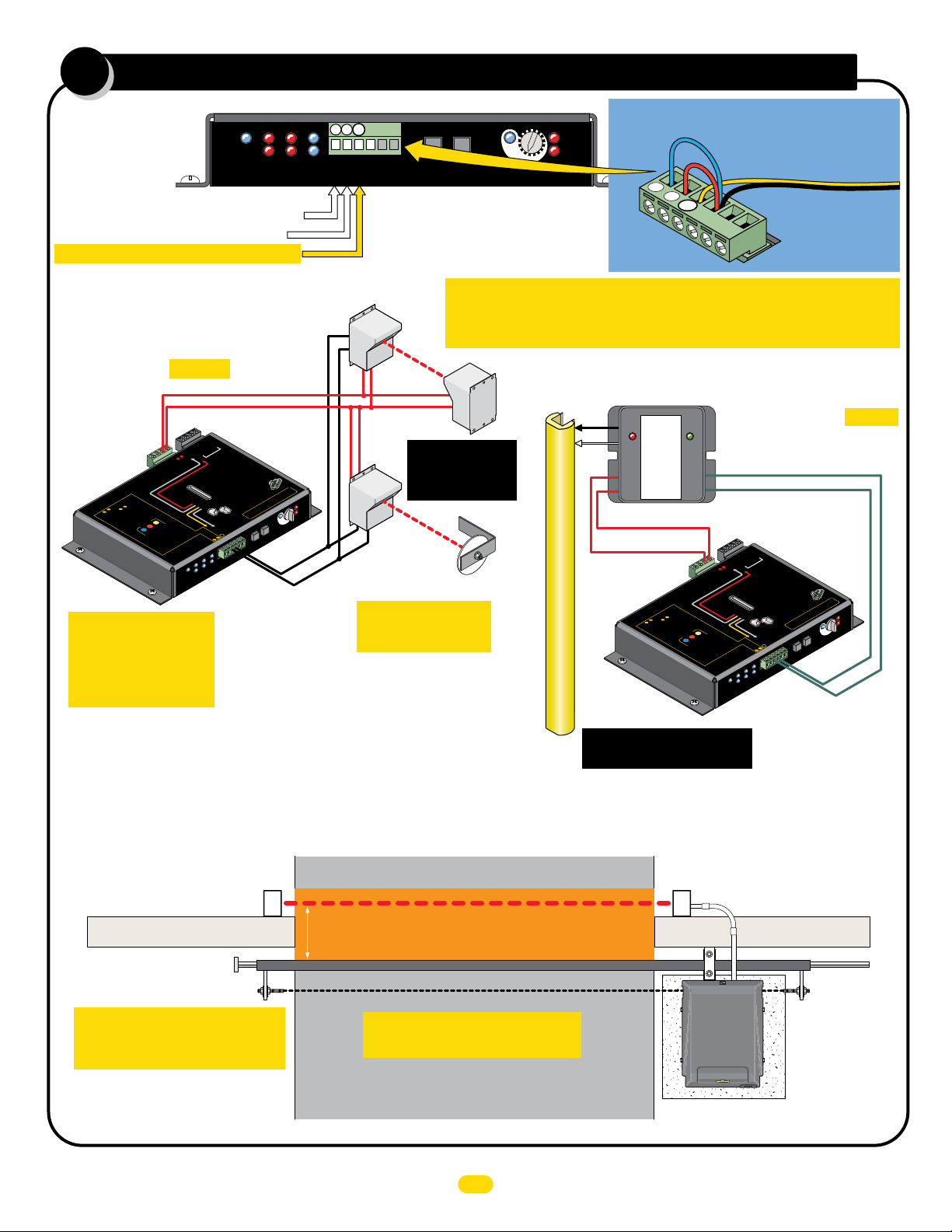
ONE Entrapment protection sensor MUST be installed or operator will
Thru-Beam
Power
Power
NOT function. It MUST be MONITORED and NORMALLY CLOSED (N.C.).
Power
Trans
See pages 21-23
for specific
photocell wiring.
Reflective
Beam
Reflector
IMPORTANT: Photocells
MUST be in alignment
or fault will occur.
MAX
LED ON
14
15
16
3
4
5
ERD
Sensitivity
13
12
ERD
Motor
OverLoad
Jumper UNUSED Entrapment Protection
3
2
1
hoto
P
Edge 2
EDGE 1
UL 325 2016 Standard
Typical HARDWiring For:
10K Edge
Normally
Closed
GEM - 104
ON = Obstruction
BLINKING = Fault
MON.
PWR
SAFETY
INPUT
GEM-104 MUST be used.
PWR 12V
Polarity does NOT matter
GND
R
TO
O
M
INPUTS
Power In
”
ED
RN
EA
OR
L
e
b
e
b
n
:
MOT
a
T
c
3
rs.
ST
&
ey
so
MUST be “
MUS
h
t
n
MU
2
3
rs
s
o
se
ts
s
&
put
u
R
n
t
n
p
2
e
i
FORE
O
S
d
s
IT
in
e
Pho
Sensing Edge
See page 24 to wire a Gate
Link wireless transmitter.
BE
D
N
s
N
r
u
ts
put
R
2
RE
t
d/o
In
MO
un
u
n
npu
TO
i
p
a
to
OP
n
i
o
e
t
Any
o LEA
e
r
g
.
T
d
h
e
.
d
d
t
h
d
MONI
e
E
re
.
it
i
e
1
r
e
g
w
e
o
p
t
earn
l
same
rsin
rd
HOLD
d
e
a
um
j
d
e
he
re
i
t
n
t
a
w
Rev
a
.
is h
s
e
M
2
s
s
p
b
n
e
re
o
e
t
P
t
b
.
u
3
il
b
t
n
u
Inputs to GND or a fault will occur.
Sensor Wire
GND
Example: Inputs 2 & 3
are NOT used and MUST
be jumpered to GND.
Normally Closed (N.C.)
Sensing Edge to EDGE 1
(CLOSING Direction ONLY)
V -
-) -
GND -
(
PWR 24
5
48
-
RS
1
-
2V
1
RS-485 (+) -
-
ND
R
-
G
MATRIX
PW
n
io
ALARM
ect
12V
IT
WR
H
P
IM
L
nt prot
ITC
me
SW
RY
E
T
rap
K
t
MC-200
C
AT
h
B
it
PA
be us
w
er en
ST
rs
so
MU
pow
Y
L
sen
N
12V
O
WR
P
MC-200
d
e
r
s
Monito
Rever
e
b
can
l
l
e
C
o
1
.
.
s
x
3
STOP
i
in
r
tr
g
&
o
e
b
Ma
EN
e
n
d
o
e
mo
im
t
rn
a
N
le
d
O
I
,
e
t
OT
a
M
c
SE
O
d
di
e
n
CL
i
t
OTOR
c
ON
.
e
n
t
e
b
mi
de
5
.
h
LL
r
n
I
c
i
l
o
a
f
W
m
,
e
s
e
s
t
5
r
dua
d
o
PEN STOP
f
in
n
ED
O
las
h
mo
L
e
it
.
ON
d
w
whe
0
rn
.
e
0
n
g
s
i
b
mo
0
lea
-2
a
in
.
0
g
p
.
C
d
rn
d
LL
a
e
n
-2
a
e
I
e
M
s
e
e
W
b
n
u
L
on
d
t
MC
o
t
s
y
n
r
ORED
re
u
b
D
a
H
o
a
T
b
I
E
s
rs
L
N
n
rs
.
o
e
o
4
OP
s
BOT
t
n
r
s.
ra
MO
e
s
o
ST
p
e
s
w
o
s
t
p
Prot
f
o
s
s
o
rn
n
a
re
g
P
re
le
nt
in
.
M
p
5
o
t
e
s a
t
e
u
me
b
p
n
I
puts:
rap
In
nt
E
h
P
R
E
POWE
MC-200
Motor Controller
or
on
1
cti
E
s
e
G
ne
D
i
rot
E
P
.)
n.
.C
idel
nt
o
N
(
ed
, to each
ncti
Gu
D
me
wired to
r
an
fu
o
SE
ap
be
c
NLY
O
tr
OT
ns
O
L
ST
n
N
e
s
C
E
S
MU
WILL
MA
tor
R
sensor
a
r
O
RE
A
N
•
ope
TO
NI
Wire
•
MO
operato
are used
g
n
•
i
dge
ed
E
r
o
hot
OR
P
Cel
Monito
Jog R
Edge
GN
D
Phot
Ed
1
ge
o
2
C
e
ll
2
n
3
er
p
ctio
ts
e
pu
jum
T
in
US
nused
u
SW
t
Limi
ge
d
E
ll
Photo
e
2
otoC
Cell
X
1
ATRI
M
N-LINE
O
Edge
UL
trap
n
r
.
Y
hen dual operators
so
L
oto Cell
n
w
L
D
N
puts
G
E
ow
p
-
dge and/or Ph
ANY
00
er
NUS
U
•
JU
Jog RT
1
In
M
2
3
C-
3
2
T be used to
0
0
n
of the
r.
MUS
sensors.
emai
cu
r
V
D
ns.
E
oc
o
12
ST
OR
ucti
ation.
MU
IT
PWR
N
MO
on instr
or fault will
inputs
D
lati
E
ce d’install
l
ED
R
E
nsta
i
MP
Jog LT
3
2
1
oir la noti
See
1
V
14
:
N:
15
O
ON
16
TI
UTI
Moto
EN
CA
TT
A
Over
3
4
N
5
MAX
O
LED
D
y
ER
Sensitivit
JOG
RIGHT
JOG
LEFT
ND (C)
G
se
200
D
-
MC
s
r’
.
ired to
w
Reversing
e
b
MC-2
•
l
Jog
L
T
T
-
-
1
Edge 1
GND
Edge 2
EDGE 1 (N.C.)
CLOSING Direction ONLY
Sl
i
d
e
ERD
r
d
Loa
Entrapment Protection Device Locations:
CLOSING Direction
Photocell
IMPORTANT: Entrapment
Protection Photocells MUST be
Monitored Normally Closed Type.
NOTE: Photo input on Matrix 1 is NOT
MONITORED (Normally OPEN) and is
NOT UL 325 entrapment protection.
Beam: 5” or LESS
from CLOSED gate.
IMPORTANT: Photocells MUST
be in alignment or fault will occur.
Outside Property
Entrapment Area
Gate Closed
Inside Property
Continued on next page.
6
CLOSING direction photocell
to MC-200 EDGE 1 input.
Run conduit to operator
Wall
UL 325 2016 Standard-MAX Quick Install Rev 8
Page 9
continued
7
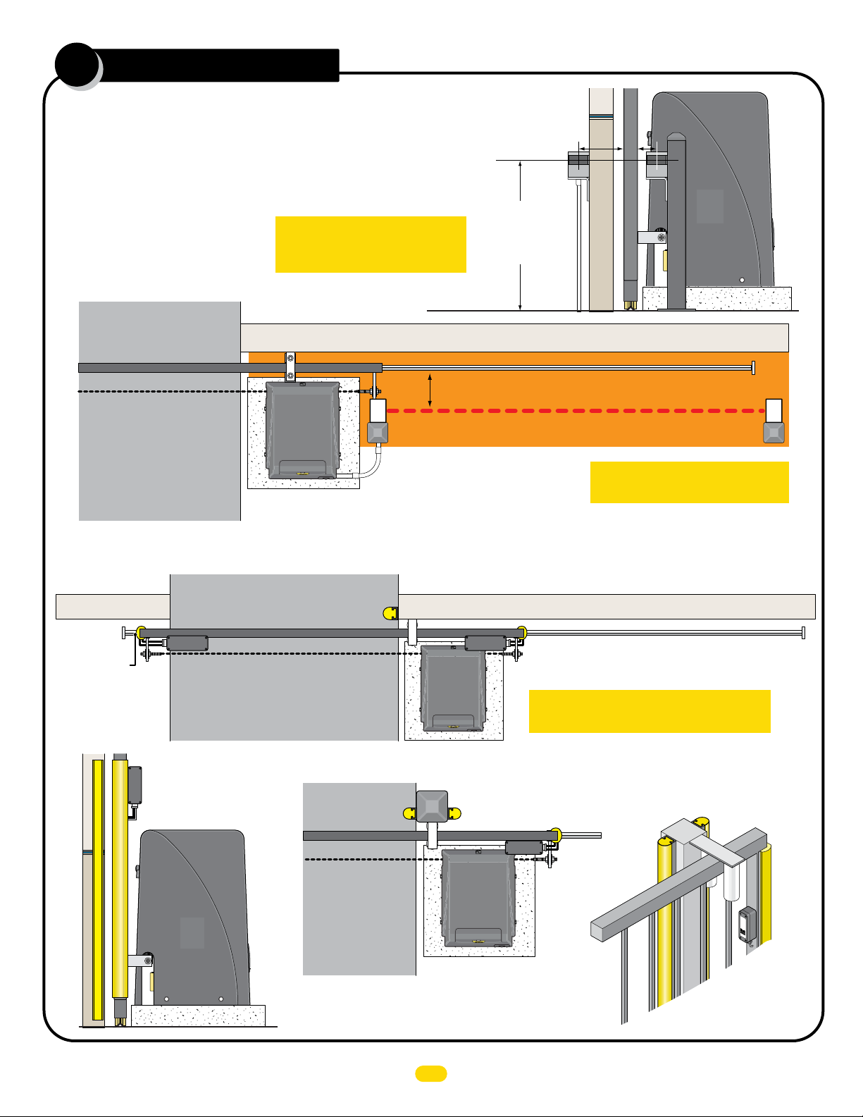
Entrapment Protection Device
Locations:
Photocell Beam Height
Install photocells on either side of
gate, as close as practical to the
gate but no further away than 5”.
Less
5”
or
Less
5”
or
OPENING Direction
Photocell
Outside Property
Gate Closed
Inside Property
Sensing Edges
Outside
Property
IMPORTANT: Entrapment
Protection Photocells MUST be
Monitored Normally Closed Type.
Beam: 5” or LESS from OPEN gate.
Run conduit to operator
OPENING direction photocell to MC-200
motor controller, Monitored. Normally
CLOSED (N.C.)
NOTE: Connect to Photo Cell input on MC-200.
Beam Height:
21” for most
installations but No
higher than 27.5”
above ground.
Wall
Entrapment Area
Inside
Property
Gate
Wall
Illustrations not to scale
Photo Beam
IMPORTANT: Photocells MUST
be in alignment or fault will occur.
CLOSING direction
10K NORMALLY CLOSED
Sensing Edge Wirelessly
Module
Wireless
Wall
NORMALLY CLOSED Sensing Edge
Wireless
Wireless Module
Module
WIRELESS NOTE: Refer to the
instruction sheet that comes
with the wireless module for
wiring and mounting instructions
when using wireless option.
OPENING direction 10K
Gate Closed
Wireless
Module
OPENING direction10K NORMALLY CLOSED Sensing Edge Wirelessly
IMPORTANT: Sensing edges MUST be
Monitored 10K Normally Closed Type.
Self-Supporting Post
OPENING direction
Sensing Edge
Gate Closed
If a self-supporting post is being used, then sensing edges need to
be installed on EACH side of the post to protect against entrapment
in the OPENING and CLOSING direction of gate travel.
CLOSING direction Sensing Edge
Wireless
Module
OPENING
direction
Sensing
Edge
Wall
OPENING
direction
Sensing
Edge
CLOSING direction
Sensing Edge
MGL-TX
M
on
2
0
ito
G
re
a
te
d
L
in
k
M
i
l
l
e
r
Ed
g
e
OPENING
direction
Sensing
Edge
(Wireless)
UL 325 2016 Standard-MAX Quick Install Rev 8
7
Page 10
learn gate positions
8
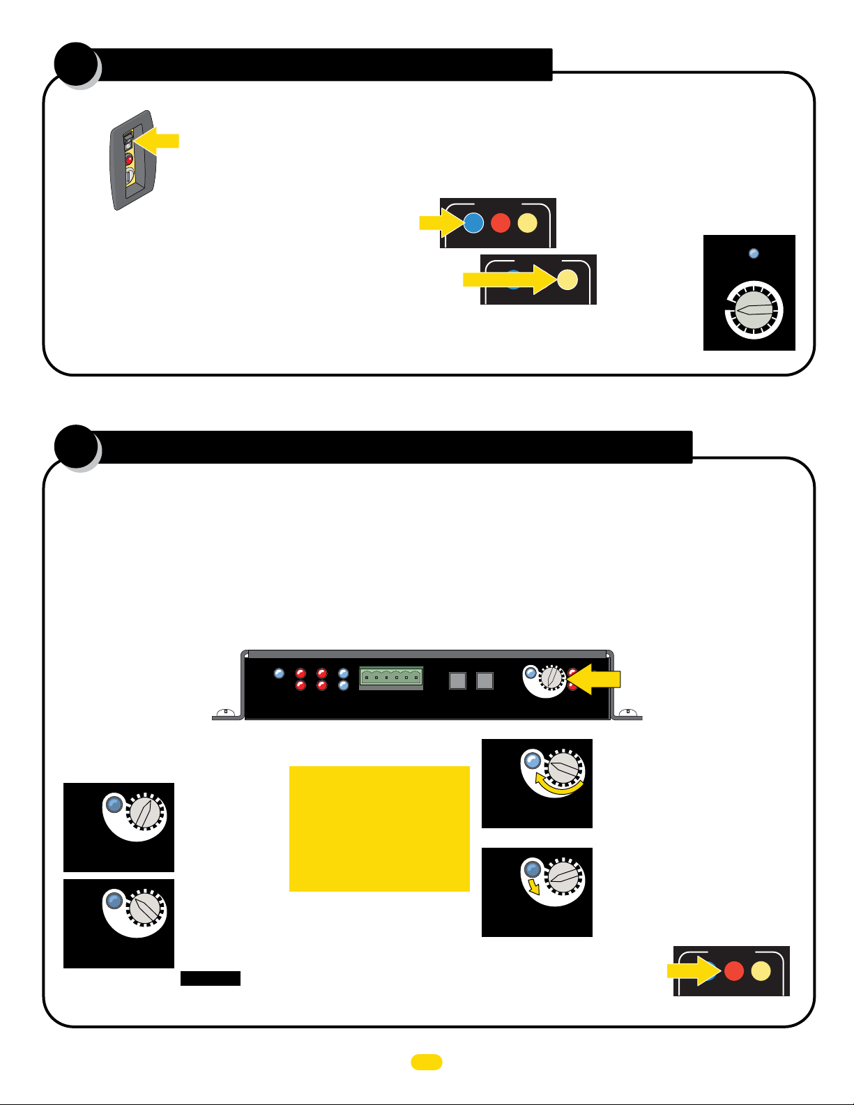
After the limit sensor activators and at least ONE entrapment sensor has been installed, put the gate in the CLOSED position:
Gate
Shut-Off
Switch
IMPORTANT:
GATE SHUT-OFF Switch MUST be OFF.
(see page 11 for more information about switch)
MOTOR MOTION
1. Push OPEN button to cycle gate to open position.
Operator cycles slowly while learning position.
2. Then push CLOSE button to cycle gate to closed position.
Operator cycles slowly while learning position.
OPEN STOP CLOSE
MOTOR MOTION
OPEN STOP CLOSE
Matrix 1
Matrix 1
MIN
MAX
After gate positions have been learned, the gate will cycle at the speed set on matrix 1 “GATE SPEED” setting.
Adjust ERD Reverse sensor
9
Matrix 1
MAX
GATE SPEED
Set to MAX
The ERD Sensor - Electronic Reversing Device (Type A) MUST be adjusted for the OPEN and CLOSE gate cycles.
When the gate encounters an obstruction during the CLOSE cycle, it will reverse to the open position and PAUSE the gate.
An input command (press remote button or exit loop) is needed BEFORE the gate will reset and close again.
When the gate encounters an obstruction during the OPEN cycle, it will reverse approximately 6 inches and PAUSE the gate.
An input command (press remote button or exit loop) is needed BEFORE the gate will reset and open again.
For the ERD Sensitivity to function correctly:
• Limit sensors must be learned BEFORE adjusting the ERD Sensitivity.
14
15
13
16
3
4
5
ERD
Sensitivity
14
15
16
3
4
5
ERD
Sensitivity
14
15
16
3
4
5
ERD
Sensitivity
12
ERD
Motor
OverLoad
13
12
16 sensitivity setting positions.
NO mechanical hard stop for knob.
Adjusting ERD:
A. Turn knob until blue LED lights up.
Maximum sensitivity reached,
Position 1 - Too sensitive for most gates.
B. Turn knob counter-clockwise to
13
12
reduce gate sensitivity while testing ERD
until desired results is attained.
(LED remains OFF for all but position 1)
Matrix 1
MOTOR MOTION
OPEN STOP CLOSE
Typical Settings:
14
15
13
16
3
4
5
ERD
15
16
3
4
5
ERD
12
14
13
12
MAX
LED ON
MAX
LED ON
Sensitivity
Sensitivity
UL
Entrap
Edge
Edge
Limit SW
2
1
MATRIX
ON-LINE
Cell
Edge 2
Photo
Edge 1
GND
Jog RT
Jog LT
PhotoCell
POWER
MC-200
Motor Controller
IMPORTANT: When satisfied
Position 13:
• Typical gate setting.
Position 16:
• Heavy gate setting.
• Long gate setting.
• Cantilever gate setting.
• Uphill gate setting.
• High wind area gate setting.
CAUTION: Position 16 results in gate exerting
MAXIMUM force before reversing direction.
with ERD adjustment, cycle
the gate 3 or 4 times to make
sure that the ERD sensor does
not falsely trigger during
normal gate operation.
Re-adjust if this happens.
MAX
LED ON
JOG
JOG
RIGHT
LEFT
MAX
LED ON
MAX
LED ON
If alarm sounds while adjusting ERD,
press STOP BUTTON on Matrix 1 to
shut-off alarm.
UL 325 2016 Standard-MAX Quick Install Rev 8
8
Page 11
10
loops & loop detectors
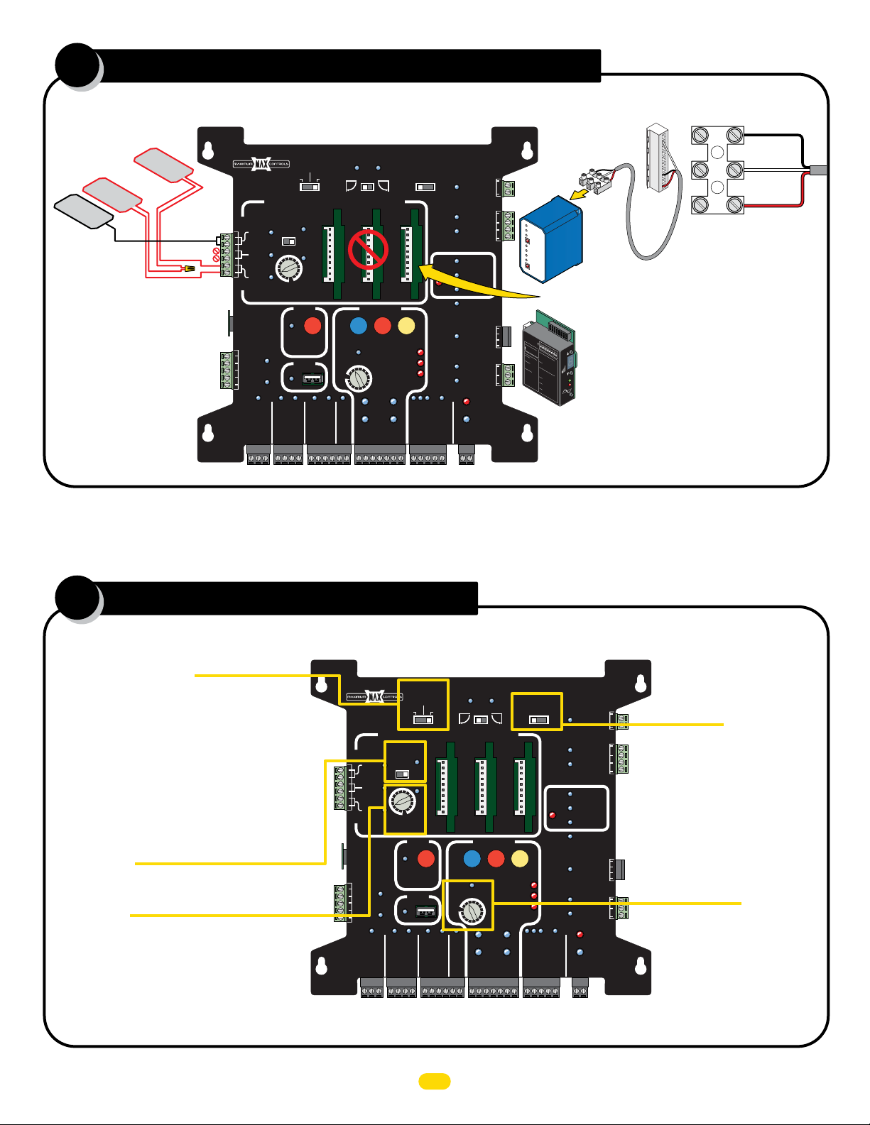
In-Ground Loops
Connections
Safety
Loop
Exit
Loop
NOTE: See manual for
more information
about loops and
loop detectors.
Safety
Loop
Safety Loops
Wired in series
MATRIX 1
MADE in USA
BATTERY
BACK-UP MODE
LEAVE
CLOSED
LEAVE
OPEN
AUTOMATIC OPEN/CLOSE CONTROLS
ANTI
TAILGATE
PLUG
ID
12VDC
GND
24VDC
GND
EXIT
CENTER
SAFETY
RADIO SIG.
RADIO GND
MIN
OFF
CLOSE TIMER
RECORDER
FIRE DEPT
GND
OFFON
MAX
PARTIAL
OPEN
POSITION
OBD PORT
BLACK BOX
MAX OPEN
GND
STRIKE
OPEN
1 TIME
GND
MAX
KEYPAD / RDR
GND
OPEN
LEFT
OPEN
MAX
GATE SPEED
MIN
PHOTOCELL
GND
PRIMARY
GATE
OPEN
RIGHT
MOTOR MOTION
LIMIT
SWITCH
ON-LINE
MOTOR
ON-LINE
PRIMARY
GATE
(+)
GND
(-)
SAFETYCENTEREXIT
STOP CLOSE
REVERSE SENSITIVITY
MOTOR OVERLOAD
NO LIMIT SWITCH /
CLAMP SLIPPING
SEC
GATE
(+)
GND
(-)
MAGLOCK
OFF
OPEN
DELAY
STOP
2Sec1.5Sec
GATE
TAMPER
UL
ENTRAP
GATE
STATUS
CLOSE
COM
GATE DISABLE
MAG
LOCK
Tamper NO
Tamper IN
PHOTOCELL
UL ALARM 12V
ALARM RET
24V
EDGE 1
EDGE 2
ID PLUG
ERROR
RESET
CLOSE
BATTERY
IN USE
POWER
GND
COM
COM
GND
GND
OPEN
COM
Com, Gnd (Black)
Loop Detect
Output (White)
NC
Power
Terminal
Wire to
Power Terminal
Power 15 VDC
(Red)
back of
External
Loop
Detector
detector
MAX External Loop Detector
Cable Adapter Sold separately
External Loop Detectors
O
N
12
OPTIONS
3
45
6
7
EDI
8
Te
l
: 480.968.64
O
DEFLECT
N
5 = Opti
OM
= In
07
mum
ETE
0
1
= Dec
c
re
R
2
S
as
ens
3
e
SW1
r
S
.
ease Sens.
ens
4
L
ED
O
5
.
S
N
INDIC
W
LMA180
P
6
OW
2
O
O
N
Fr
7
N
ON
ER
ATORS
=
equenc
O
8
= Norm
O
FF
SENS
F
Low
O
ON
F
FF
O
= Medium
FF
=
y
DETEC
N
OFF
= Medium-H
al Powe
o
SW
P
ON = Detect
ow
3
T
O
er
-Low
= Hi
N
r
OF
=
O
gh
F
FF
=
Fail
2
igh
N
= Fa
H
o
SW4
z
S
De
Flas
L
ecur
oop
t
il
ec
h
O
=
S
S
N
e
t
De
1 Flash
W
afe
ON = Pul
Fa
l
5
a
ETER
O
ul
y Tim
N
2
t
O
O
F
ut
la
O
=
i
ng
p
FF
s
O
3
h
ut B
FF
LECTOM
pen
e
O
Flas
s=
O
EF
s
= B
Sh
FF
e
D
L
h
N = Pu
oo
es=2
on Entr
O
o
s
r
SW
ted
p
am
Bo
F
5
6
F
% chang
Loop
e as
th
l
ON
of
y
se
LE
= Loop Fault
SENS
=
A
on Ex
In
D’
Curren
O
d
s Flas
e
u
FF
PWR
2 Sec
c
ta
it
= No Delay
t Loo
nc
SW
h
in
L
e
R
on
E
g=
Pr
7
p
D Flas
E
d Delay
O
F
e
ault
vio
N
=
us
h
O
POW
in
FF
L
g
N
oo
=
ormal
T
=
p Fa
SW
Infi
I
ul
8
P
O
t
ETEC
n
re
N
it
D
=
ED
e
s
en
P
O
re
FF
c
S
e
s
en
= No Sens
ence
s
i
tivi
t
y
Boos
i
ti
T
Plug-In Loop Detectors
v
t
i
t
y
Boost
ESE
R
NOTE: DO NOT select the PULSED output
option for Loop Detectors.
NOTE: DO NOT set Loop Detectors to
HIGH sensitivity to avoid false trigger.
11
matrix 1 settings
Battery Back-Up Mode
LEAVE OPEN - After a power failure and battery power is
drained, the next open command, gate will remain OPEN.
Gate will automatically close after AC power is restored.
LEAVE CLOSED - After a power failure and battery power
is drained, gate will remain CLOSED. See manual for more
information about opening a CLOSED gate during a power
failure (emergency open device, manual open, etc).
OPEN 1 TIME - After a power failure, gate automatically
OPENS and REMAINS OPEN, even after power is restored.
A close command or loop event is needed to close gate.
Anti Tailgate
Set to OFF
See manual before enabling this feature.
Close Timer
1st click clockwise - Knob at MIN position: 1/2 sec...
2nd click clockwise: 1 sec...
3rd click: 4 sec...
4th click: 8 sec... etc up to 60 sec. MAX.
See manual for more info.
MATRIX 1
MADE in USA
BATTERY
BACK-UP MODE
LEAVE
CLOSED
LEAVE
OPEN
AUTOMATIC OPEN/CLOSE CONTROLS
ANTI
TAILGATE
PLUG
ID
12VDC
GND
24VDC
GND
EXIT
CENTER
SAFETY
RADIO SIG.
RADIO GND
OFFON
MAX
MIN
OFF
CLOSE TIMER
POSITION
RECORDER
OBD PORT
BLACK BOX
FIRE DEPT
GND
MAX OPEN
PARTIAL
OPEN
GND
STRIKE
OPEN
1 TIME
GND
MAX
KEYPAD / RDR
GND
OPEN
LEFT
OPEN
MAX
GATE SPEED
MIN
PHOTOCELL
GND
PRIMARY
GATE
OPEN
RIGHT
MOTOR MOTION
SWITCH
ON-LINE
MOTOR
ON-LINE
PRIMARY
GATE
(+)
GND
SAFETYCENTEREXIT
STOP CLOSE
REVERSE SENSITIVITY
MOTOR OVERLOAD
NO LIMIT SWITCH /
CLAMP SLIPPING
LIMIT
SEC
GATE
(-)
(+)
GND
(-)
MAGLOCK
DELAY
OFF
OPEN
STOP
2Sec1.5Sec
GATE
TAMPER
UL
ENTRAP
GATE
STATUS
CLOSE
COM
GATE DISABLE
MAG
LOCK
Tamper NO
Tamper IN
PHOTOCELL
UL ALARM 12V
ALARM RET
24V
EDGE 1
EDGE 2
ID PLUG
ERROR
RESET
CLOSE
BATTERY
IN USE
POWER
GND
COM
NC
COM
See manual before enabling this feature.
GND
GND
OPEN
COM
See manual for more info.
Maglock Delay
Set to OFF
Gate Speed
Set to MAX
UL 325 2016 Standard-MAX Quick Install Rev 8
9
Page 12
12
wiring opening device options
250 mA Max.
12 VDC
OR 24 VDC
Radio Power
3-Wire
Radio
MATRIX 1
ID
PLUG
12VDC
GND
24VDC
GND
MADE in USA
EXIT
CENTER
SAFETY
RADIO SIG.
BATTERY
BACK-UP MODE
LEAVE
CLOSED
LEAVE
OPEN
AUTOMATIC OPEN/CLOSE CONTROLS
ANTI
TAIL GATE
OFFON
MIN
MAX
OFF
CLOSE TIMER
PARTIAL
OPEN
POSITION
RECORDER
OBD PORT
BLACK BOX
STRIKE
FIRE DEPT
GND
MAX OPEN
GND
RADIO GND
OPEN
1 TIME
GND
MAX
KEYPAD / RDR
GND
OPEN
LEFT
OPEN
MAX
GATE SPEED
MIN
PHOTOCELL
GND
PRIMARY
GATE
OPEN
RIGHT
MOTOR MOTION
LIMIT
SWITCH
ON-LINE
MOTOR
ON-LINE
PRIMARY
GATE
(+)
GND
(-)
SAFETYCENTEREXIT
STOP CLOSE
REVERSE SENSITIVITY
MOTOR OVERLOAD
NO LIMIT SWITCH /
CLAMP SLIPPING
SEC
GATE
(+)
GND
(-)
MAGLOCK
DELAY
OFF
OPEN
STOP
2Sec1.5Sec
GATE
TAMPER
UL
ENTRAP
GATE
STATU S
CLOSE
COM
MAG
LOCK
UL ALARM 12V
GATE DISABLE
Tamper NO
GND
Tamper IN
PHOTOCELL
EDGE 1
EDGE 2
ID PLUG
ERROR
ALARM RET
RESET
CLOSE
BATTERY
IN USE
POWER
24V
GND
COM
COM
GND
OPEN
COM
+
Pos
NC
Neg
Pos
Neg
-
+
-
maglock option
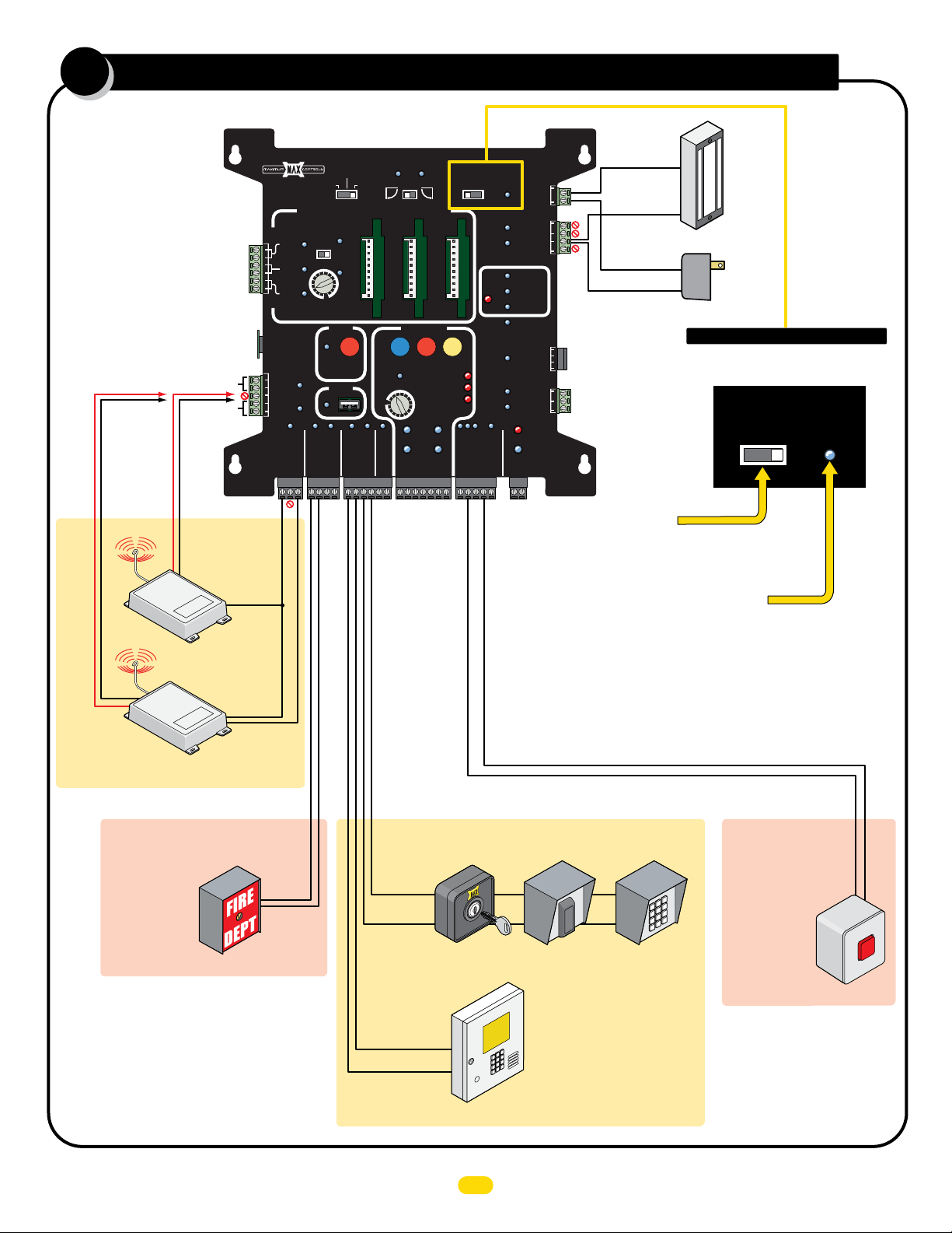
Maglock MUST be connected as shown
when used.
MAGLOCK DELAY:
You MUST select a time delay when using
a maglock. Maglock power disengages 1.5
sec or 2 sec before gate starts opening.
MAGLOCK LED (Monitors Maglock):
ON - Locked OFF - Unlocked
Flashing - Problem with Maglock Power.
Maglock
Maglock
Power
MAGLOCK
DELAY
OFF 2Sec1.5Sec
MAG
LOCK
re
i
4-W
Radio
Normal Opening Devices
Emergency Open Device
Emergency OPEN
(Overrides gate
disable switch)
NOTE: See manual for more info.
(N.O.)
Dry Contact
(N.O.)
Telephone
Entry
Dry Contact (N.O.)
Dual Gate Operators using Maglock: Primary gate opens FIRST.
Install maglock accordingly to account for this.
Normal Opening Devices
Key Switch
Card Reader
Separate power
for Devices if required.
Keypad
External Alarm
Reset Button
Security Device
StopCom
PRESS
T
to RESE
UL 325 2016 Standard-MAX Quick Install Rev 8
10
Page 13
gate shut-off switch
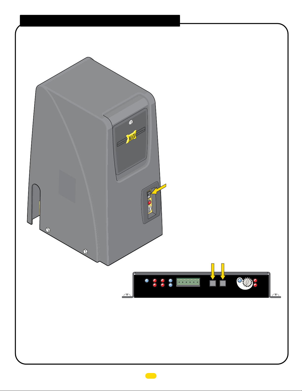
Turn this feature ON while servicing the gate operator. This switch disables all OPEN/CLOSE devices BUT the JOG LEFT/RIGHT buttons
on MC-200 so gate can not accidentally get activated while operator is being serviced.
IMPORTANT: When the Gate Shut-Off switch is turned ON,
any OPEN/CLOSE command given to gate operator will just
“BEEP” for a few seconds and ignore command.
Gate Shut-Off Switch
Only the Jog Left or Jog Right buttons will operate
gate when Gate Shut-Off switch is turned ON.
UL
Entrap
Edge
Edge
Limit SW
2
1
MATRIX
ON-LINE
PhotoCell
POWER
MC-200
Motor Controller
MAX MC-200 motor controller
Cell
Edge 2
Photo
Edge 1
GND
14
15
13
16
3
4
5
ERD
Sensitivity
12
Motor
OverLoad
ERD
MAX
Jog RT
Jog LT
JOG
LEFT
JOG
RIGHT
LED ON
TECHNICIAN MAINTENANCE TIP: One wire can be unplugged from the back of the Gate Shut-Off switch after servicing the
operator to prevent the switch from accidentally being turned ON during normal operation. Plug the wire back in and turn ON the
switch only while servicing the operator. This can prevent an unnecessary service call by a technician when the only thing wrong
with a malfunctioning operator is the Gate Shut-Off switch has accidentally been turned ON but the owner is unaware of this.
UL 325 2016 Standard-MAX Quick Install Rev 8
11
Page 14
T
T
R
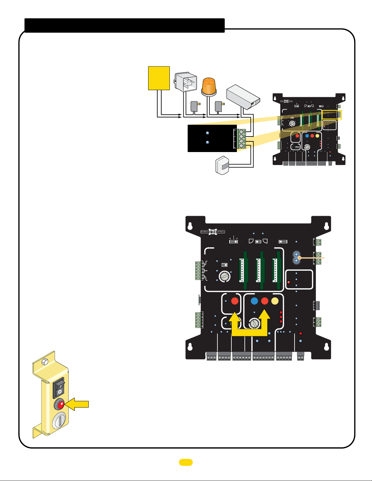
gate tamper feature
ID
UG
PARTIAL
O
CLOS
MAX
PHOTOCELL
OFF
S
CENTER
EXIT
GATE
Tamper NO
Many different safety devices can be wired to the GATE TAMPER. After device is wired to relay, it MUST be ARMED to function.
Wiring Gate Tamper
The GATE TAMPER can be used for various functions
such as turning a warning light, siren or camera on
Existing
Building
Alarm
System
when the gate is tampered with (Vandalized Gate).
The gate operator defines a “Vandalized Gate” as
UNAUTHORIZED movement of the gate. This can
occur if the chain is dropped and gate is manually
moved from the closed position or the gate is forced
open from the closed position without authorization.
TAMPER NO/Com Relay: Connect a warning light, siren, camera or
an existing alarm system to relay.
TAMPER IN/GND Input: Connect a sensor device to input. When
Tamper In/GND gets triggered, device that is wired to Tamper relay
(NO/Com) will activate.
Arm Gate Tamper (Turn ON)
The GATE TAMPER is factory set to OFF (Unarmed). It MUST be turned
ON (Armed) or safety device connected to the GATE TAMPER relay will
NOT activate.
• Press and HOLD the STOP button while simultaneously pressing
the POSITION RECORDER button. Hold BOTH buttons down until
Gate Tamper LEDs light up then turn OFF and a beep is heard.
Gate Tamper is now ARMED (ON).
NOTE: DO NOT press the POSITION RECORDER button before
the STOP button or Gate Tamper will NOT Arm.
• To UNARM (Turn OFF) Gate Tamper repeat above step.
When GATE TAMPER is triggered, the
OPERATOR ALARM and GATE TAMPER
relay will activate. The operator will shut
down all operating functions.
The alarm reset button MUST be pressed to
turn OFF the alarm and reset the operator.
If GATE TAMPER is armed and relay is connected to
an existing building alarm system, then they will get a
triggering of their alarm system and should be
notified of the situation.
Siren
Power
GATE
TAMPER
Warning
Light
Power
Tamper NO
COM
GND
Tamper IN
Motion
Sensor
MATRIX 1
ID
PLUG
12VDC
GND
24VDC
GND
MADE in USA
EXIT
CENTER
SAFETY
BATTERY
BACK-UP MODE
LEAVE
CLOSED
LEAVE
OPEN
AUTOMATIC OPEN/CLOSE CONTROLS
ANTI
TAILGATE
OFFON
MIN
MAX
OFF
CLOSE TIMER
PARTIAL
OPEN
POSITION
RECORDER
OBD PORT
BLACK BOX
Press Together
STRIKE
FIRE DEPT
GND
MAX OPEN
RADIO GND
GND
RADIO SIG.
OPEN
1 TIME
GND
KEYPAD / RDR
Security
Camera
PRIMARY
OPEN
LEFT
OPEN
MAX
GATE SPEED
MIN
MAX
PRIMARY
PHOTOCELL
GND
GND
GATE
OPEN
RIGHT
MOTOR MOTION
STOP CLOSE
REVERSE SENSITIVITY
MOTOR OVERLOAD
NO LIMIT SWITCH /
LIMIT
SWITCH
ON-LINE
MOTOR
ON-LINE
GATE
(+)
GND
(-)
SAFETYCENTEREXIT
CLAMP SLIPPING
SEC
GATE
(+)
GND
(-)
MAGLOCK
DELAY
OFF
OPEN
PLUG
PL
MATRIX 1
ID
12VDC
GND
24VDC
GND
STOP
MADE in USA
EXIT
CENTER
SAFETY
BATTERY
BACK-UP MODE
LEAVE
CLOSED
LEAVE
OPEN
OPEN
1 TIME
AUTOMATIC OPEN/CLOSE CONTROLS
ANTI
TAILGATE
OFFON
OFFON
MIN
MAX
OFF
CLOSE TIMER
E TIMER
PARTIAL
PEN
OPEN
POSITION
RECORDER
MAX
OBD PORT
BLACK BOX
MIN
MAX
STRIKE
GND
KEYPAD / RDR
GND
FIRE DEPT
GND
MAX OPEN
GND
RADIO SIG.
RADIO GND
MAG
2Sec1.5Sec
LOCK
Tamper NO
GATE
TAMPER
Tamper IN
PHOTOCELL
UL
EDGE 1
ENTRAP
EDGE 2
ID PLUG
UL ALARM 12V
ALARM RET
GATE
STATUS
24V
GND
CLOSE
COM
GATE DISABLE
PRIMARY
GATE
OPEN
LEFT
MOTOR MOTION
OPEN
GATE SPEED
PRIMARY
GATE
PHOTOCELL
GND
(+)
COM
COM
GND
ERROR
RESET
GND
OPEN
COM
CLOSE
BATTERY
IN USE
POWER
RIGHT
SWITCH
ON-LINE
MOTOR
ON-LINE
GND
NC
OPEN
STOP CLOSE
REVERSE SENSITIVITY
LIMIT
(-)
SAFETYCENTEREXIT
MOTOR OVERLOAD
NO LIMIT SWITCH /
CLAMP SLIPPING
SEC
GATE
(+)
AFETY
GND
(-)
MAGLOCK
DELAY
MAG
OFF
2Sec1.5Sec
LOCK
GATE
TAMPER
PHOTOCELL
ENTRAP
UL ALARM 12V
GATE
STATUS
OPEN
STOP
CLOSE
COM
GATE DISABLE
Gate Tamper
LEDs
Tamper NO
Tamper IN
ALARM RET
24V
COM
NC
COM
GND
EDGE 1
EDGE 2
ID PLUG
ERROR
RESET
GND
OPEN
COM
CLOSE
BATTERY
IN USE
POWER
GND
Alarm Reset Button
UL 325 2016 Standard-MAX Quick Install Rev 8
12
Page 15
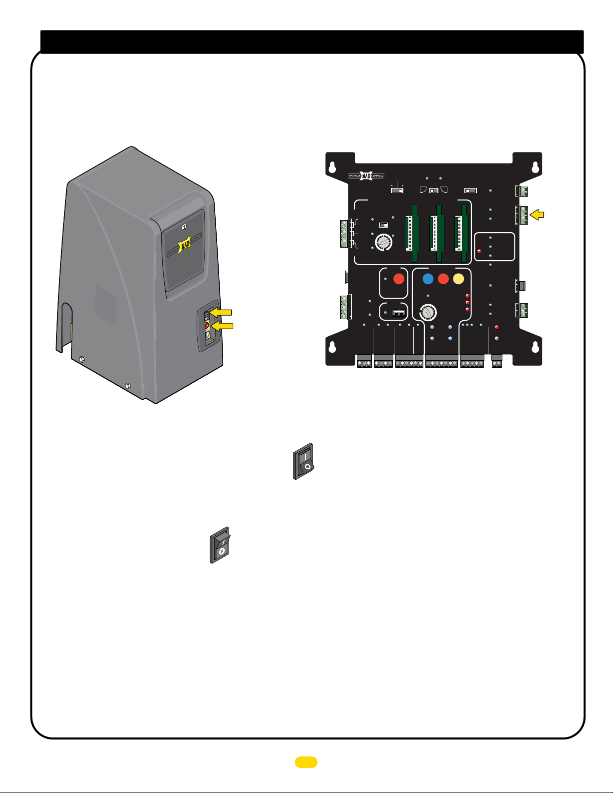
Dropping the Chain - GATE TAMPER is ARMED (ON)
The GATE TAMPER is factory set to OFF (Unarmed). See previous page for more information about ARMING GATE TAMPER.
If an existing alarm system (Building alarm system) is connected to the GATE TAMPER relay (see previous page), notify proper
authorities BEFORE dropping the chain.
Gate Shut-Off Switch
Alarm Reset Button
PROPER Dropping of Chain while GATE TAMPER is ARMED:
MATRIX 1
MADE in USA
BATTERY
BACK-UP MODE
LEAVE
CLOSED
LEAVE
OPEN
AUTOMATIC OPEN/CLOSE CONTROLS
ANTI
TAILGATE
EXIT
OFFON
CENTER
SAFETY
MAX
MIN
OFF
CLOSE TIMER
PARTIAL
RADIO SIG.
RADIO GND
RECORDER
FIRE DEPT
GND
OPEN
POSITION
OBD PORT
BLACK BOX
MAX OPEN
GND
STRIKE
PLUG
ID
12VDC
GND
24VDC
GND
OPEN
1 TIME
GND
KEYPAD / RDR
GND
MAX
GATE SPEED
MIN
MAX
PHOTOCELL
GND
PRIMARY
GATE
OPEN
LEFT
MOTOR MOTION
OPEN
PRIMARY
GATE
(+)
OPEN
RIGHT
STOP CLOSE
REVERSE SENSITIVITY
MOTOR OVERLOAD
NO LIMIT SWITCH /
LIMIT
SWITCH
ON-LINE
MOTOR
ON-LINE
GND
(-)
SAFETYCENTEREXIT
CLAMP SLIPPING
SEC
GATE
(+)
GND
(-)
MAGLOCK
OFF
OPEN
DELAY
STOP
2Sec1.5Sec
TAMPER
UL
ENTRAP
STATUS
CLOSE
GATE
GATE
COM
MAG
LOCK
UL ALARM 12V
GATE DISABLE
Tamper NO
Tamper IN
PHOTOCELL
EDGE 1
EDGE 2
ID PLUG
ERROR
ALARM RET
RESET
BATTERY
POWER
24V
GND
COM
COM
GND
GND
OPEN
CLOSE
IN USE
NC
Gate
Tamper
Relay
COM
1. Turn Gate Shut-Off switch ON to disable operator alarm.
2. Drop the Chain.
ON
OFF
Gate
Shut-Off
3. GATE TAMPER relay WILL be activated.
4. Service operator.
5. Reconnect the chain to gate.
ON
6. Turn Gate Shut-Off switch OFF.
Gate
OFF
Shut-Off
7. Rearm an alarm system that may be connected to the GATE TAMPER relay.
IMPROPER Dropping of Chain (Vandalize):
Gate Shut-Off switch is NOT turned ON.
When the chain is improperly dropped (Vandalized), the OPERATOR ALARM and GATE TAMPER relay will activate. The operator will shut
down all operating functions.
The alarm reset button MUST be pressed to turn OFF the alarm and reset the operator. If GATE TAMPER relay is connected to an existing
building alarm system, then they will get a triggering of their alarm system and should be notified of the situation.
UL 325 2016 Standard-MAX Quick Install Rev 8
13
Page 16
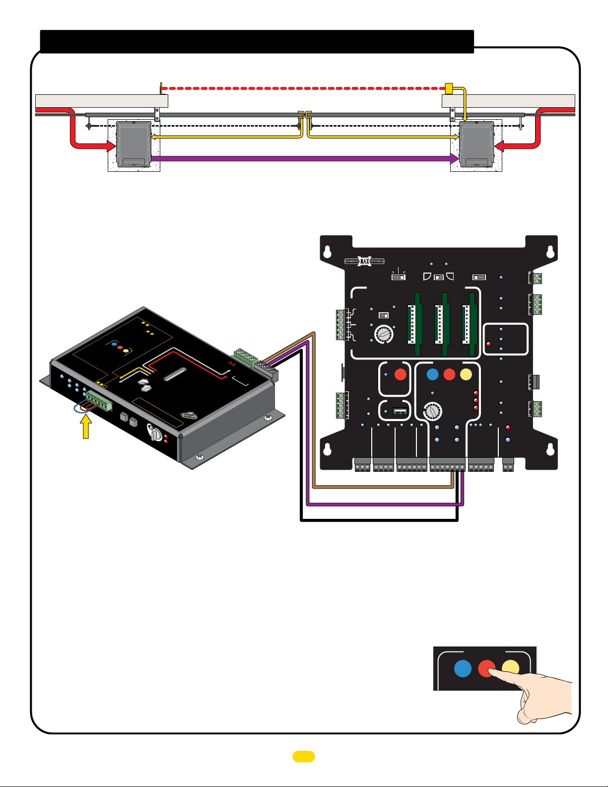
dual gate operators wiring
G
N
D
1
2
3
Reflector
AC input
power
To Secondary MC-200 Edge 2 or Photo Cell Input To Primary MC-200 Edge 2 or Photo Cell Input
Secondary Operator
NO Matrix 1
Secondary Operator
MC-200
2.
R
be
eversing
3.
Press and
w
buttons at the
ired to either input 2 or 3.
until
beep
is heard, learn mode begi
MOTOR MOTION
Learn mode last
by beeping.
4.
O
LE
PEN
sens
D
s
for
WIL
S
o
TOP
operators are used.
B
r on MC
5.
L be
OTH
s
P
ress S
l
e
arn sens
nt
P
MUST jump
e
d
in
TOP
MO
r
otec
puts
Cell
MC
-200s
button again w
o
rs
a
nd end learn mode,
N
IT
OR
E
D.
tion
er
Photo
Edge 2
Edge 1
fo
CLO
r
ON
5
-200.
min. indi
f
o
r each detected
LED
w
s
hen
WILL
d
ual
be
ON
i
thin 5 min.
Photo Cell
Ed
Edge
ge
2
GN
1
23
D
g
1
RT
-
-
-
Jog RT
GND
Jog LT
LEFT
to
beeping stops.
Inputs are now
Entrap
Inputs:
m
e
unus
PhotoCel
POWER
l
Edge
MC-200
Limit SW
Motor Controller
2
UL
Entrap
1
Edge
MATRIX
ON-LINE
Jumper ALL Entrapment
Protection Inputs to GND
on Secondary MC-200
when ONLY using
CLOSE photocell.
• AC input power to EACH gate operator.
j
umpe
SE
cated
Jo
JOG
H
w
l
e
arned.
O
LD
s
am
Jog LT
1.
ired to inputs
red.
e time on
Inputs &
to MO
To
LE
MO
A
N
ITORED
Any unused inputs
E
dg
e and/or
the
O
P
E
Matr
A
TTENTI
JO
G
RI
G
H
RN
N
&
C
T
2
N
ITOR
in
puts & :
Sensors
B
E
FORE
P
ho
to
STO
ix
1
ns.
AUTION:
MAX
LED ON
s
C
P
O
3
enso
2
they can be
ell can
N
MOTOR
MUS
T
r
s.
3
MUS
T be
MU
S
T
Mo
P
Cell
•
U
JUMPER
See installatio
:
Vo
ir la no
16
3
ERD
Sensiti
be “L
b
e
OR
n
ho
15
4
R
i
tore
NUSED
5
e
t
o
pow
14
vit
EARNED”
Monitored
versi
Edge
d
•
be
•
MC-2
e
r
MO
in
ED
or fa
n
tice
d
’in
13
1
2
OverLoa
y
ng
R
wire
0
0
p
uts
in
stal
Moto
NI
ER
are used.
e
versing
d
PWR 1
TORED
MUST
ult will occur.
st
ru
l
atio
D
P
MON
ope
to
ctio
n
r
ower In
MC-200
•
W
ra
to
Ed
ANY of the
2V
M
se
remain
n
s.
.
d
ge
ope
ir
e
ITORE
r’
s MC-
a
US
n
sors
S
li
de
PW
•
NORM
0
O
R
A
se
rato
nd
/o
T
be
.
3
0
MO
I
NPUT
TO
R
S
NL
Y
p
sensor
o
1
2V
M
US
Entr
Sensor Guidelines
n
sor
M
r W
ILL
AL
D
LY CLOSED (
s
e
n
2
sors
00
wh
en
r
Ph
3
o
to Cell ca
In
p
uts.
u
se
d
to
GND
2
1
MC-2
To MC-200 EDGE 1 Input
Sensing Edges
AC input
power
Three RS-485 Wires to Matrix 1 (See below)
NOTE: See manual for more information
about Dual Gate Operator installation.
Primary Operator
Matrix 1
Matrix 1 Primary Operator
STRIKE
OPEN
1 TIME
GND
KEYPAD / RDR
MAX
MIN
MAX
GND
PRIMARY
GATE
OPEN
LEFT
MOTOR MOTION
OPEN
GATE SPEED
PRIMARY
GATE
PHOTOCELL
GND
(+)
OPEN
RIGHT
STOP CLOSE
REVERSE SENSITIVITY
MOTOR OVERLOAD
NO LIMIT SWITCH /
LIMIT
SWITCH
ON-LINE
MOTOR
ON-LINE
GND
(-)
SAFETYCENTEREXIT
CLAMP SLIPPING
SEC
GATE
(+)
GND
(-)
MAGLOCK
DELAY
OFF
TAMPER
OPEN
STOP
CLOSE
SEC
GATE
2Sec1.5Sec
GATE
UL
ENTRAP
GATE
STATUS
COM
MAG
LOCK
UL ALARM 12V
GATE DISABLE
Tamper NO
Tamper IN
PHOTOCELL
EDGE 1
EDGE 2
ID PLUG
ERROR
ALARM RET
RESET
CLOSE
BATTERY
IN USE
POWER
24V
GND
COM
COM
GND
GND
OPEN
COM
NC
MATRIX 1
MADE in USA
BATTERY
BACK-UP MODE
LEAVE
CLOSED
LEAVE
OPEN
AUTOMATIC OPEN/CLOSE CONTROLS
ANTI
TAILGATE
EXIT
OFFON
CENTER
PLUG
ID
12VDC
GND
24VDC
GND
SAFETY
RADIO SIG.
MIN
CLOSE TIMER
FIRE DEPT
RADIO GND
MAX
OFF
PARTIAL
POSITION
RECORDER
OBD PORT
BLACK BOX
GND
MAX OPEN
OPEN
GND
BAT
T
P
ER
AC
Y
K
L
IM
SWITCH
IT
wer
e
AL
s
n
ARM
tra
w
it
pm
h M
e
C-20
n
-
t
protect
-
0 PWR 12
-
D
i
-
on
T b
e
use
d
apment
US
Protec
T
b
e
N
wi
OT
r
e
fu
d to
n
ctio
n.
O
NL
N.C.
Y
d
,
ua
to
l o
e
a
per
ch
a
tors
n
V
GN
V
) -
12
(+
5
-
RS-48
IX
RS-485 (-) -
1
D
N
G
PWR 24V -
PWR
MATR
tio
n
ED
G
E 1
o
r
)
RS-485 (+) to RS-485 (+)
RS-485 (-) to RS-485 (-)
RS-485 GND to RS-485 GND
• Entrapment protection (CLOSE photocell) to PRIMARY GATE OPERATOR MC-200.
- Jumper any UNUSED entrapment protection inputs to GND on BOTH MC-200s or a fault will occur.
- See manual if installing more entrapment protection devices than just a CLOSE photocell.
• Opening device to the PRIMARY GATE OPERATOR.
• Matrix 1 Open Left - Open Right set for the PRIMARY GATE OPERATOR opening direction.
(Secondary operator automatically set to opposite opening direction)
• OPTIONAL - In-ground loop wires to the PRIMARY GATE OPERATOR.
Alarm Shut-OFF
NOTE: The Alarm Shut-Off is located on the Primary gate operator ONLY.
There is NO alarm shut-off button on the secondary gate operator.
Matrix 1
STOP Button
UL 325 2016 Standard-MAX Quick Install Rev 8
14
MOTOR MOTION
OPEN STOP CLOSE
Page 17
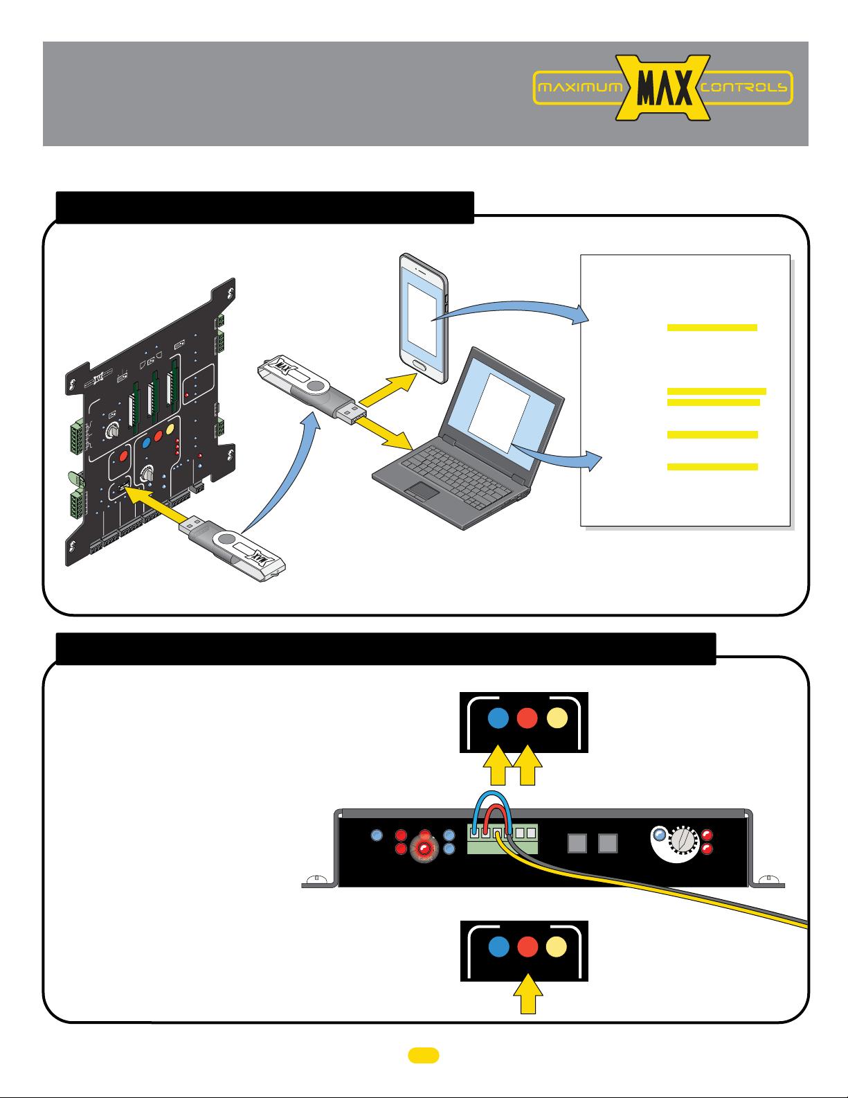
Troubleshooting
222
2
www.max.us.com
This page and the next 5 pages can help troubleshoot problems that might occur after installation is complete.
usb black box port
Download a simple .txt file to troubleshoot
gate operator errors and view event history.
COM
MAG
K
NC
LOCK
c
MAGLOC
2Se
DELAY
c
1.5Se
F
OF
PRIMARY
GATE
MATRIX
DE in
MA
XIT
E
R
CENTE
Y
SAFET
MAX 1700FS
ID
PLUG
12VDC
D
GN
C
4VD
2
D
GN
RADIO SIG.
PE
Y
OPEN
TER
L
BAT
E
V
LEA
BACK-UP MODE
OPEN
1 TIME
CLOSED
AVE
LE
N
E
OP
TIC OPEN/CLOSE CONTROL
EXIT
TE
F
OF
MAX
F
F
R
L
IA
PART
OPEN
OPEN
X
MA
GATE SPEED
ON
POSITI
N
MI
RECORDER
X
RT
MA
X
PO
OBD
BLACK BO
GND
PHOTOCELL
GND
KEYPAD / RDR
GND
STRIKE
GND
MAX OPEN
FT
E
MOTOR MOTION
PRIMAR
GATE
GND
(+)
O
RIGHT
STOP
E
R
LIMIT
SWITCH
ON-LIN
MOTOR
ON-LIN
Y
(-)
Matrix 1
1
USA
AUTOMA
ANTI
TAILGA
ON
N
MI
O
CLOSE TIME
GND
FIRE DEPT
RADIO GND
N
VERSE SENSITIVIT
MO
NO LIMIT SW
Tamper NO
COM
D
GN
GATE
Tamper IN
S
TAMPER
SAFETYCENTER
PHOTOCELL
EDGE 1
EDGE 2
UL
LUG
P
R
RA
ID P
T
EN
ERRO
T
T
UL ALARM 12V
RESE
ALARM RE
GND
OPEN
COM
E
CLOS
CLOSE
Y
GATE
Y
ATUS
TTER
ST
BA
OVERLOAD
/
OR
T
M
A
CL
E
E
SEC
TE
GA
(+)
IN USE
ITCH
IPPING
SL
P
POWER
GND
24V
GATE DISABLE
COM
CLOSE
STOP
OPEN
(-)
GND
MAX Flash Drive
t
r
d
o
p
ob
Smart Phone
SB Phone
o
p
b
o
d
r
t
U
Adapter
equired
R
OR
Computer
Event History Text Document Sample
Event type clarificaon:
INFO: informaonal message only
WARNING: unusual event but doesn't cause system malfuncon
ERROR: abnormal event, could cause system malfuncon
ENTRAP: entrapment detecon event
Event Report:
Fri 07/11/2014 10:59:41 INFO : Cycle Counter
Fri 07/11/2014 10:59:41 ENTRAP : SEC_MC: First ERD Detected
Fri 07/11/2014 10:59:37 INFO : Radio Input Deacvated
Fri 07/11/2014 10:59:36 INFO : Radio Input Acvated
Fri 07/11/2014 10:58:54 INFO : PRI_MC: Fully Open Posion Learned
Fri 07/11/2014 10:58:53 INFO : SEC_MC: Fully Open Posion Learned
Fri 07/11/2014 10:57:40 INFO : PRI_CIO: Communicaon Established
Fri 07/11/2014 10:57:38 ENTRAP : PRI_MC: Photo Cell Deacvated
Fri 07/11/2014 10:57:34 ENTRAP : PRI_MC: Photo Cell Acvated
Fri 07/11/2014 10:57:21 INFO : Radio Input Deacvated
Fri 07/11/2014 10:57:21 INFO : Radio Input Acvated
Fri 07/11/2014 10:56:46 WARNING: PRI_MC: Tamper Reported
Fri 07/11/2014 10:56:36 INFO : SEC_MC: Fully Open Posion Unknown
Fri 07/11/2014 10:56:36 INFO : PRI_MC: Fully Open Posion Unknown
Fri 07/11/2014 10:56:36 WARNING: PRI_MC: Tamper Reported
Fri 07/11/2014 10:56:33 ENTRAP : PRI_MC: Photo Cell Deacvated
Fri 07/11/2014 10:56:33 ENTRAP : PRI_MC: Photo Cell Acvated
Fri 07/11/2014 10:56:33 ENTRAP : PRI_MC: Photo Cell Deacvated
Fri 07/11/2014 10:56:33 ENTRAP : PRI_MC: Photo Cell Acvated
1. Plug MAX USB flash drive into OBD port of Matrix 1. OBD LED will flash while file is downloading.
Remove flash drive after LED stops flashing.
2. Plug flash drive into any computer USB port OR smart phone using a USB phone adapter.
The most recent 1000 events can be viewed. No special software required.
test edge 1 entrapment sensor
Troubleshoot EDGE 1 entrapment protection sensor.
1. Press and HOLD the STOP button while simultaneously pressing
the OPEN button. Hold BOTH buttons down until beeping is heard,
learn mode begins.
NOTE: DO NOT press the OPEN button before the STOP button
or learn mode will NOT begin.
2. EDGE 1 LED should be ON MC-200 if an
entrapment sensor is detected. If EDGE 1 LED
is NOT on, wiring to photocell is bad, photocell
is out of alignment, photocell is wired wrong,
photocell is bad, or sensor is
MC-200
Motor Controller
NOT normally closed (N.C.), etc.
3. Press STOP button again within 5 min. to end learn mode, beeping stops.
NOTE: If STOP button is not pressed within 5 min.
learn mode automatically end after 5 min.
POWER
PhotoCell
UL
Entrap
Edge
Edge
15
Limit SW
2
1
MATRIX
ON-LINE
OPEN STOP
Edge 2
Edge 1
Photo
Cell
OPEN
MOTOR MOTION
Jumpers
Jog RT
Jog LT
GND
MOTOR MOTION
STOP
CLOSE
CLOSE
JOG
LEFT
Matrix 1
15
16
MAX
LED ON
3
4
JOG
RIGHT
5
ERD
Sensitivity
Matrix 1
UL 325 2016 Standard-MAX Quick Install Rev 8
14
13
12
ERD
Motor
OverLoad
Sensor Wire
Page 18
gate cycling troubleshooting
Use this table to help with troubleshooting AND operator LED troubleshooting on the next 4 pages.
Refer to MAX 1500/2200/F18 installation owner manuals for more information.
Gate Symptom Solutions (what to check)
Gate beeps but will not open
or close for any command
given.
Gate moves slowly.
Gate beeps when opening
and closing.
Gate does NOT open.
Gate does NOT close.
Gate stops prematurely and
beeps, moves in opposite
direction.
Gate will stop before
reaching desired limit
setting.
Gate stops abruptly while in
motion.
Gate re-opens while closing.
Gate does not learn new
magnet positions.
• Check GATE SHUTOFF switch, it should be OFF. Turn switch ON then OFF again, possible chain drop event and switch needs
to be recycled. GATE DISABLE LED should be OFF.
• Check if OPEN and CLOSE Limits have been learned. Refer to Learn Gate Positions section and learn limits.
• Check if GATE SPEED rotary dial is set to MAX position (LED on).
• Gate may be too heavy for operator (check manual for maximum gate weight for your model operator).
• Check if "BATTERY IN USE" LED is ON. If so, gate is on Battery back up mode and battery is running low.
• Operator may be in battery back up mode. check if Mode 1 switch is ON on the back of Matrix 1.
• Check if “Gate in Motion” Alarm feature is ON (“Mode 0” switch is on back of Matrix 1 and set to “ON”).
• Check if Power LEDs are ON on both Matrix 1 and MC-200. Check if “MOTOR ON-LINE” LED and “LIMIT SWITCH ON-LINE”
LED are both ON on Matrix 1.
• Check if PRIMARY GATE "open RIGHT / open LEFT" switch is set properly.
• Check if GATE SHUTOFF switch is OFF (GATE DISABLE LED should be OFF)
• Check if GATE DISABLE LED is ON. If so, check if GATE DISABLE input is active.
• Check if "EDGE 2" LED or "PHOTOCELL" LED is ON or BLINKING on MC-200. If so, check entrapment sensor wiring or
missing jumper.
• Check if “BATTERY IN USE“ LED is ON. IF so, battery may be too low and gate is kept closed (BATTERY BACK-UP MODE
switch set to “Leave Closed“).
• Check if Power LEDs are ON on both Matrix 1 and MC-200. Check if “MOTOR ON-LINE“ LED and “LIMIT SWITCH ON-LINE”
LED are both ON on Matrix 1.
• Check if “EDGE 1“ LED is ON or BLINKING on MC-200. If so, check entrapment sensor wiring and alignment.
• Check if any loops are active, check SAFETY LOOP or EXIT LOOP LED is ON.
• Check if any open command inputs are active (check if LED is ON on the matrix 1 for: RADIO, FIRE DEPT, MAX OPEN,
STRIKE, KEYPAD/RDR, PHOTOCELL). Check device connected to the input that LED light is turned ON.
• Check if PRIMARY GATE “open RIGHT / open LEFT” switch is set properly.
• Check if GATE SHUTOFF switch is OFF (GATE DISABLE LED should be OFF)
• Check if GATE DISABLE LED is ON. If so, check if GATE DISABLE input is active.
• If “EDGE 2“ LED or “PHOTOCELL“ LED is ON or BLINKING on MC-200. If so, check entrapment sensor wiring or missing
jumper.
• If “BATTERY IN USE” LED is ON and BATTERY BACK-UP MODE switch = “Leave Open”, then battery may be too low and gate
is kept OPEN.
• If “BATTERY IN USE” LED is ON and BATTERY BACK-UP MODE switch is set to “OPEN 1-TIME”, then if AC power is lost, gate
will automatically open 1 time.
• If “CLOSE TIMER” is OFF, then gate will not close automatically. A close command (i.e radio, close) is required to close gate.
• Loop detector is defective (EXIT, or SAFETY).
• Loop has a short or open. Measure loop resistance.
• If “ERD“ LED is ON, an obstruction (ERD event) is detected. If no apparent obstruction, select a less sensitive ERD setting.
• If “EDGE 2“ LED is ON, entrapment sensor is triggered or jumper on connector is broken.
• Gate Open and Close Limits have not been learned properly. Relearn limit positions using jog RT and jog LT.
• The magnet(s) are not installed in correct limit position on the chain.
• Only for OPENING gate (not during closing cycle): Check if PARTIAL OPEN feature is turned ON. Relearn partial open position
or turn off PARTIAL OPEN feature.
• If “MATRIX ON-LINE” LED or “LIMIT SWITCH ON-LINE” LED are OFF on MC-200, then check wiring between (MC-200 &
Matrix 1) or (MC-200 and Limit switch box).
• Check if “PHOTOCELL” LED is ON on MC-200. If so, check entrapment sensor wiring or missing jumper
• Motor hall sensor cable may be compromised. Unplug cable from MC-200 “Motor Inputs” and ensure wires are not broken
and are crimped properly.
• Check if closing photo cell is misaligned with reflector (check photocell on MC-200 “EDGE 1” input or Matrix 1 “Photocell”
input.
• Check if SAFETY LOOP is set too sensitive, then gate itself triggers SAFETY loop and reopens gate. Desensitize SAFETY LOOP
detector.
• Use jog LEFT/RIGHT buttons to learn new positions instead of using open or close buttons on Matrix 1.
UL 325 2016 Standard-MAX Quick Install Rev 8
16
Page 19
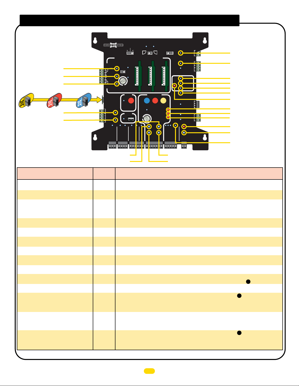
matrix 1 led troubleshooting
1. EXIT LOOP
2. CENTER LOOP
3. SAFETY LOOP
ID plug MUST be plugged in.
1500
MAX
MAX 1500
MAX 2200
MAX 2200
4. 12 VDC
5. 24 VDC
6. SECONDARY LIMIT SWITCH ON-LINE
7. PRIMARY LIMIT SWITCH ON-LINE
Matrix 1 LED
Problem Condition
“ID PLUG” LED is FLASHING on Matrix 1 and
board beeping
“POWER” LED is OFF
“BATTERY IN USE” LED is ON
“BATTERY IN USE” and “POWER” LED are
FLASHING
PRIMARY “MOTOR ON-LINE” LED is OFF
SECONDARY “MOTOR ON-LINE” LED is OFF
PRIMARY “LIMIT SWITCH ON-LINE” LED is
OFF
SECONDARY “LIMIT SWITCH ON-LINE” LED is
OFF
“UL Entrap” LED is ON
“REVERSE SENSITIVITY” LED is FLASHING
“EDGE 1” LED is ON
“EDGE 1” LED is flashing
“EDGE 2” LED is ON
“EDGE 2” LED is FLASHING
MAX F18
MAX F18
MATRIX 1
ID
PLUG
12VDC
GND
24VDC
GND
Normal
LED
OFF
15
ON
21
OFF
20
OFF / ON
20 / 21
ON
9
ON
8
ON
7
ON
6
OFF
16
OFF
17
OFF
13
OFF
13
OFF
14
OFF
14
STRIKE
OPEN
1 TIME
GND
MAX
KEYPAD / RDR
GND
OPEN
LEFT
OPEN
MAX
GATE SPEED
MIN
PHOTOCELL
GND
PRIMARY
GATE
RIGHT
MOTOR MOTION
SWITCH
ON-LINE
MOTOR
ON-LINE
PRIMARY
GATE
(+)
GND
OPEN
SAFETYCENTEREXIT
STOP CLOSE
REVERSE SENSITIVITY
MOTOR OVERLOAD
NO LIMIT SWITCH /
CLAMP SLIPPING
LIMIT
SEC
GATE
(-)
(+)
GND
(-)
MAGLOCK
OFF
OPEN
DELAY
STOP
2Sec1.5Sec
GATE
TAMPER
UL
ENTRAP
GATE
STATUS
CLOSE
COM
GATE DISABLE
MAG
LOCK
Tamper NO
Tamper IN
PHOTOCELL
ID PLUG
UL ALARM 12V
ALARM RET
24V
COM
COM
GND
EDGE 1
EDGE 2
ERROR
RESET
GND
OPEN
CLOSE
BATTERY
IN USE
POWER
GND
COM
NC
10. MAGLOCK
11. GATE TAMPER
12. PHOTOCELL
13. EDGE 1
14. EDGE 2
15. ID PLUG ERROR
16. UL ENTRAPMENT
17. REVERSE SENSITIVITY
18. MOTOR OVERLOAD
19. NO LIMIT SWITCH
CLAMP SLIPPING
20. BATTERY IN USE
21. POWER
22. GATE DISABLE
BATTERY
BACK-UP MODE
LEAVE
CLOSED
LEAVE
MADE in USA
OPEN
AUTOMATIC OPEN/CLOSE CONTROLS
ANTI
TAILGATE
EXIT
OFFON
CENTER
SAFETY
MIN
MAX
OFF
CLOSE TIMER
PARTIAL
OPEN
POSITION
RECORDER
OBD PORT
BLACK BOX
FIRE DEPT
GND
MAX OPEN
RADIO GND
GND
RADIO SIG.
8. SECONDARY MOTOR ON-LINE
9. PRIMARY MOTOR ON-LINE
Solution(s) for
Problem Condition
• Insert ID PLUG module that is tethered to chassis into “ID PLUG” connector of Matrix 1.
• Check if AC POWER ON/OFF SWITCH is ON.
• Check 24 V wiring from MC-200 PRIMARY.
• AC power is lost, operator is in battery back-up mode.
• Check if AC POWER ON/OFF SWITCH is ON.
• Measure power input DC voltage on Matrix 1 (“24V/GND” - 2-pin black connector), (expected reading
34 VDC if AC on, 25VDC if on battery back-up).
• Battery not plugged in to BATTERY IN port on battery charger (BC-7 module)
• Check wiring between Matrix 1 RS485 (+,-, gnd) and PRIMARY MC-200 RS485 (+,-, gnd) terminals,
connect [(+) to (+)], [(-) to (-)] and [GND to GND]
• Check wiring between Matrix 1 RS485 (+,-, gnd) and SECONDARY MC-200 RS485 (+,-, gnd) terminals,
connect [(+) to (+)], [(-) to (-)] and [GND to GND].
• Check if limit switch box is plugged into PRIMARY MC-200 “LIMIT SWITCH” input on back and MC-200
is powered ON.
• Check if limit switch box is plugged into SECONDARY MC-200 “LIMIT SWITCH” input on back and
MC-200 is powered ON.
• An entrapment event has occurred, check if an entrapment sensor was triggered (see if EDGE 1,
EDGE 2, or PHOTOCELL LED is on).
• An ERD event may have occurred. Check for gate obstruction.
• ERD sensitivity is too high for application. Re-adjust ERD setting on MC-200, (see ).
• Sensor on EDGE 1 input (photocell or edge) may have detected an obstruction while closing gate.
• Photocell on EDGE 1 input is misaligned with reflector.
• Sensor on EDGE 1 input (photocell or edge) may not be wired properly, (see ).
• Sensor is NOT a N.C. monitored sensor that is UL325 2016 compliant.
• Sensor is damaged or malfunctioning.
• Sensor might need to be re-learned.
• Jumper between EDGE 2 and GND is missing or broken (jumper is required if a sensor is not present).
Sensor on EDGE 2 input (photocell or edge) may have detected an obstruction while opening or closing
gate.
• Photocell on EDGE 2 input is misaligned with reflector.
• Sensor on EDGE 2 input (photocell or edge) may not be wired properly, (see ).
• Sensor is NOT a N.C. monitored sensor that is UL325 2016 compliant.
• Sensor on EDGE 2 is damaged or malfunctioning.
• Sensor might need to be re-learned.
Table continued on next page
UL 325 2016 Standard-MAX Quick Install Rev 8
17
9
7
7
Page 20
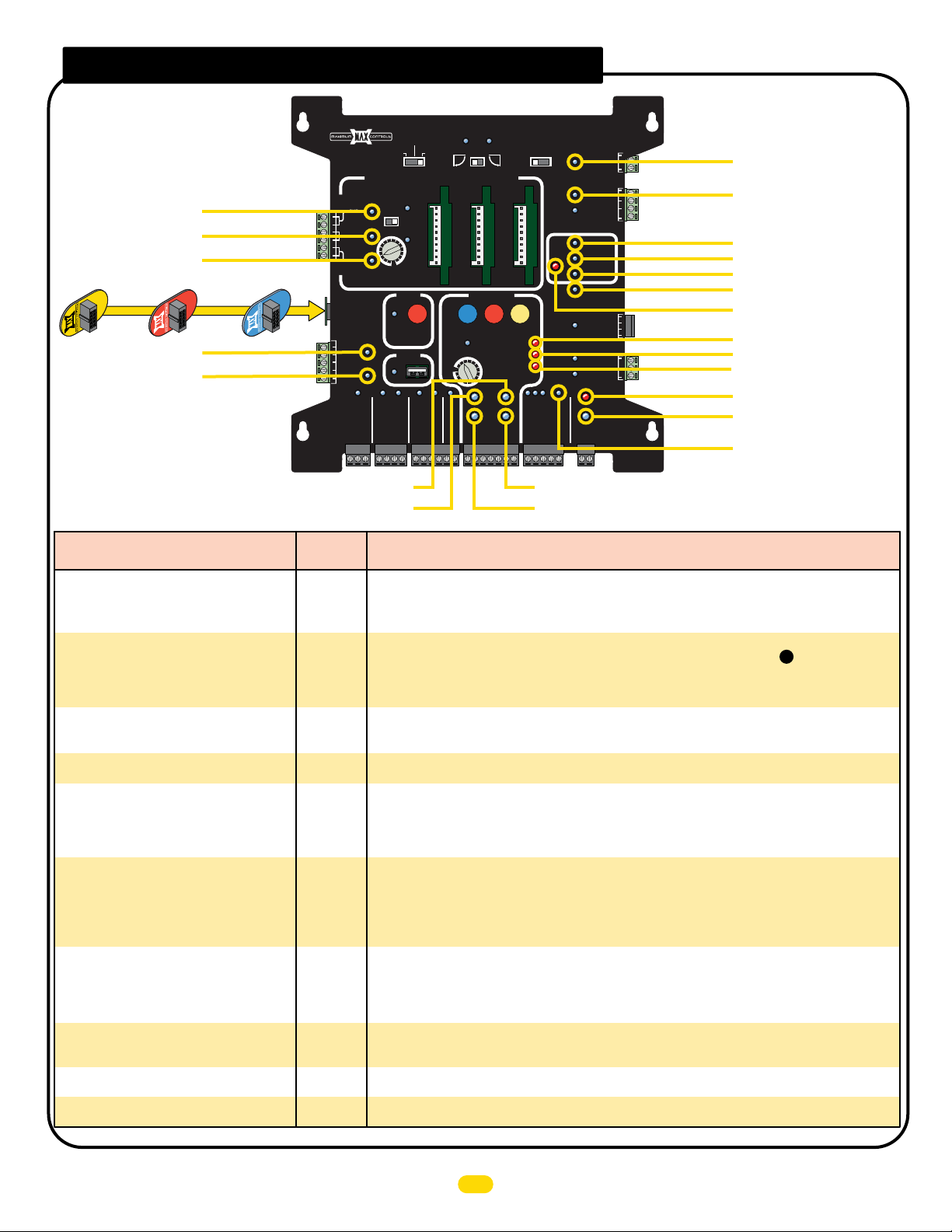
matrix 1 led continued
1. EXIT LOOP
2. CENTER LOOP
3. SAFETY LOOP
ID plug MUST be plugged in.
1500
MAX
MAX 1500
MAX 2200
MAX 2200
4. 12 VDC
5. 24 VDC
6. SECONDARY LIMIT SWITCH ON-LINE
7. PRIMARY LIMIT SWITCH ON-LINE
Matrix 1 LED
Problem Condition
“PHOTOCELL” LED is ON
“PHOTOCELL” LED is FLASHING
“MOTOR OVERLOAD” LED is ON
“NO LIMIT SW / CLAMP SLIPPING” LED is ON
“EXIT” LOOP LED is FLASHING or
contstantly ON
“SAFETY” LOOP LED is FLASHING or
contstantly ON
“GATE DISABLE” LED is ON
“MAG LOCK” LED is FLASHING
“GATE TAMPER” LED is FLASHING
“12VDC” LED is OFF. “24VDC” LED is OFF
MAX F18
MAX F18
MATRIX 1
ID
PLUG
12VDC
GND
24VDC
GND
Normal
LED
OFF
12
OFF
12
OFF
18
OFF
19
OFF
1
OFF
3
OFF
22
OFF
10
OFF
11
ON
4 or 5
BATTERY
BACK-UP MODE
LEAVE
CLOSED
LEAVE
MADE in USA
OPEN
AUTOMATIC OPEN/CLOSE CONTROLS
ANTI
TAILGATE
EXIT
OFFON
CENTER
SAFETY
MIN
MAX
OFF
CLOSE TIMER
PARTIAL
OPEN
POSITION
RECORDER
OBD PORT
BLACK BOX
FIRE DEPT
GND
MAX OPEN
RADIO GND
GND
RADIO SIG.
STRIKE
OPEN
1 TIME
GND
MAX
KEYPAD / RDR
GND
OPEN
LEFT
OPEN
MAX
GATE SPEED
MIN
PHOTOCELL
GND
PRIMARY
GATE
RIGHT
MOTOR MOTION
SWITCH
ON-LINE
MOTOR
ON-LINE
PRIMARY
GATE
(+)
GND
OPEN
SAFETYCENTEREXIT
STOP CLOSE
REVERSE SENSITIVITY
MOTOR OVERLOAD
NO LIMIT SWITCH /
CLAMP SLIPPING
LIMIT
SEC
GATE
(-)
(+)
GND
(-)
MAGLOCK
OFF
OPEN
DELAY
STOP
2Sec1.5Sec
GATE
TAMPER
UL
ENTRAP
GATE
STATUS
CLOSE
COM
GATE DISABLE
MAG
LOCK
Tamper NO
Tamper IN
PHOTOCELL
ID PLUG
UL ALARM 12V
ALARM RET
24V
COM
COM
GND
EDGE 1
EDGE 2
ERROR
RESET
GND
OPEN
CLOSE
BATTERY
IN USE
POWER
GND
COM
NC
10. MAGLOCK
11. GATE TAMPER
12. PHOTOCELL
13. EDGE 1
14. EDGE 2
15. ID PLUG ERROR
16. UL ENTRAPMENT
17. REVERSE SENSITIVITY
18. MOTOR OVERLOAD
19. NO LIMIT SWITCH
CLAMP SLIPPING
20. BATTERY IN USE
21. POWER
22. GATE DISABLE
8. SECONDARY MOTOR ON-LINE
9. PRIMARY MOTOR ON-LINE
Solution(s) for
Problem Condition
• Jumper between PHOTOCELL and GND is missing or broken (jumper is required if a sensor is not
present).
• Sensor on PHOTOCELL input (photocell or edge) may have detected an obstruction while opening or
closing gate.
• Photocell on PHOTOCELL input is misaligned with reflector.
• Sensor on PHOTOCELL input (photocell or edge) may not be wired properly, (see ).
• Sensor is NOT a N.C. monitored sensor that is UL325 2016 compliant.
• Sensor on PHOTOCELL is damaged or malfunctioning.
• Sensor might need to be re-learned.
• Check if gate is binding against catch post or bracket in opened or closed position.
• Check if gate moves manually with low resistance throughout its full range of motion.
• Check if chain is installed inline with idle wheels in both OPEN and CLOSED positions.
• Gate may be too heavy for operator (check manual for maximum gate capacity).
• Check if OPEN and CLOSE magnets are still connected on chain.
• Loop fault condition: Check if EXIT loop wires are connected into to loop input connector properly.
• Check if loop detector is inserted properly in Matrix 1 slot.
• Set unique loop detector frequency for each loop detector used.
• Loop Detector might be defective. Replace defective loop detector.
NOTE: RENO loop detector LED’s flash as default, but function normally (ignore the flashing).
• Loop fault condition: check if SAFETY loop wires are connected into to loop input connector properly.
• Check if SAFETY loops are wired in series.
• Check if loop detector is inserted properly in Matrix 1 slot.
• Set unique loop detector frequency for each loop detector used.
• Loop Detector might be defective. Replace defective loop detector.
NOTE: RENO loop detector LED’s flash as default, but function normally (ignore the flashing).
• Check if “Gate Shut-off” switch is ON, Turn it OFF. If it is OFF, cycle the switch (ON then OFF).
• Check if the chain is dropped. If so, gate is disabled for safety. Re-install chain and cycle the "Gate
Shut-off" switch (ON then OFF) to enable operator.
• Check if an external device is triggering GATE DISABLE input on Matrix 1. Disconnect devices
individually to determine possible false triggering of GATE DISABLE.
• Maglock power is lost. Check if maglock power transformer is wired properly to Matrix 1 or needs to be
replaced.
• Switch is set to delay but no maglock is connected. Set switch to OFF
• Gate was manually moved off of its CLOSED position causing Tamper Relay to trigger for few seconds.
• Check for a short in wiring to connected device. DO NOT power external keypads or telephone entry to
this port (only use for radio receiver / photocell).
7
UL 325 2016 Standard-MAX Quick Install Rev 8
18
Page 21
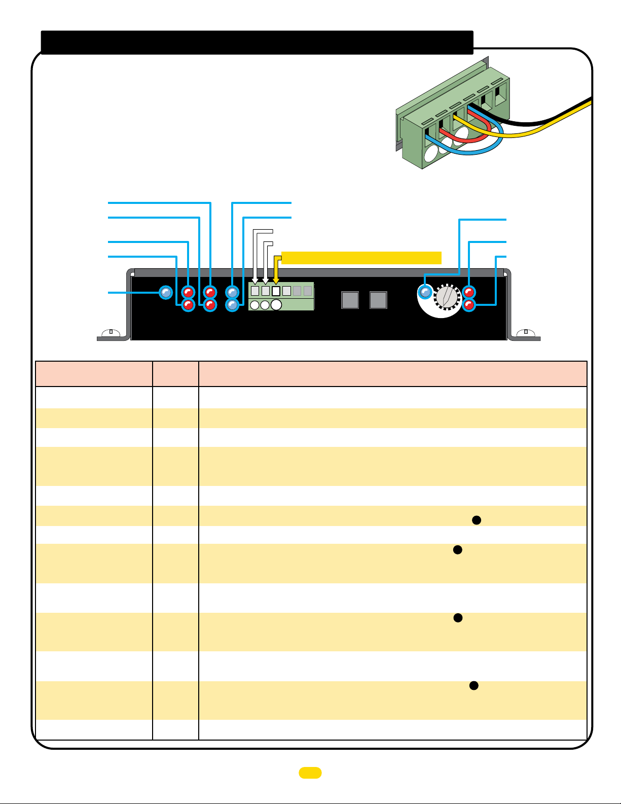
mc-200 led troubleshooting
Jumper UNUSED Entrapment Inputs
to GND or a fault will occur.
10. EDGE 2
9. EDGE 1
8. PHOTOCELL
7. UL ENTRAPMENT
6. POWER
MC-200 LED
Problem Condition
“POWER” LED is OFF
“MATRIX ON-LINE” LED is OFF
“Limit SW ON-LINE” LED is OFF
“MOTOR OVERLOAD” LED is ON
“UL Entrap” LED is ON
“ERD” LED is ON
“EDGE 1” LED is ON
“EDGE 1” LED is flashing
“EDGE 2” LED is ON
“EDGE 2” LED is FLASHING
“PhotoCell” LED is ON
“PhotoCell” LED is FLASHING
“MAX” LED is ON
PhotoCell
POWER
MC-200
Motor Controller
UL
Entrap
Normal
LED
ON
6
ON
4
ON
5
OFF
1
OFF
7
OFF
2
OFF
9
OFF
9
OFF
10
OFF
10
OFF
8
OFF
8
OFF
3
Example: Inputs 2 & 3
are NOT used and MUST
be jumpered to GND.
3
Photo
Cell
GND
1
GND
2
Edge 1
Edge 2
Sensor Wire
5. LIMIT SWITCH ON-LINE
Edge
Edge
Limit SW
2
1
MATRIX
ON-LINE
4. MATRIX ON-LINE
Photo Cell: LEARNED MONITORED OPEN/CLOSE
Edge 2: LEARNED MONITORED OPEN/CLOSE
EDGE 1: MONITORED CLOSE ONLY
2
3
1
Edge 1
GND
Jog RT
Jog LT
JOG
LEFT
Cell
Edge 2
Photo
JOG
RIGHT
MAX
LED ON
14
15
16
3
4
5
ERD
Sensitivity
13
12
Motor
OverLoad
3. MAX LED
2. ERD
1. MOTOR OVERLOAD
ERD
ENTRAPMENT INPUTS
Solution(s) for
Problem Condition
• Check if AC POWER ON/OFF SWITCH (on MAX toroid box) is ON.
• Check if power cable is plugged into back of MC-200 “Power In” input.
• Check wiring between Matrix 1 RS485 (+,-, gnd) and MC-200 RS485 (+,-, gnd) terminals. Connect [(+) to
(+)], [(-) to (-)] and [GND to GND].
• Check if limit switches are plugged into MC-200 “LIMIT SWITCH” input on back.
• Check if gate is binding against catch post or bracket in opened or closed position.
• Check if gate moves manually with low resistance throughout its full range of motion.
• Check if chain is installed inline with idle wheels in both OPEN and CLOSED positions.
• Gate may be too heavy for operator (check manual for maximum gate weight for your model operator).
• An entrapment event has occurred, check an entrapment sensor was triggered (see if ERD, EDGE 1, EDGE 2, or
PHOTOCELL LED is on).
• An ERD event may have occurred. Check for gate obstruction.
• ERD sensitivity is too high for application. Re-adjust ERD setting on MC-200, (see ).
• Sensor on EDGE 1 input (photocell or edge) may have detected an obstruction while closing the gate.
• Photocell on EDGE 1 input is misaligned with reflector.
• Sensor on EDGE 1 input (photocell or edge) may not be wired properly, (see ).
• Sensor is NOT a N.C. monitored sensor that is UL325 2016 compliant.
• Sensor is damaged or malfunctioning.
• Sensor might need to be re-learned.
• Jumper between EDGE 2 and GND is missing or broken (jumper is required if a sensor is not present).
• Sensor on EDGE 2 input (photocell or edge) may have detected an obstruction while opening or closing the gate.
• Photocell on EDGE 2 input is misaligned with reflector.
• Sensor on EDGE 2 input (photocell or edge) may not be wired properly, (see ).
• Sensor is NOT a N.C. monitored sensor that is UL325 2016 compliant.
• Sensor on EDGE 2 is damaged or malfunctioning.
• Sensor might need to be re-learned.
• Jumper between PHOTOCELL and GND is missing or broken (jumper is required if a sensor is not present).
• Sensor on PHOTOCELL input (photocell or edge) may have detected an obstruction while opening or closing gate.
• Photocell on PHOTOCELL input is misaligned with reflector.
• Sensor on PHOTOCELL input (photocell or edge) may not be wired properly, (see ).
• Sensor is NOT a N.C. monitored sensor that is UL325 2016 compliant.
• Sensor on PHOTOCELL is damaged or malfunctioning.
• Sensor might need to be re-learned.
• MOST sensitive setting for ERD entrapment detection. Select a less sensitive setting (recommended level 13 thru 16)
10
7
7
7
UL 325 2016 Standard-MAX Quick Install Rev 8
19
Page 22
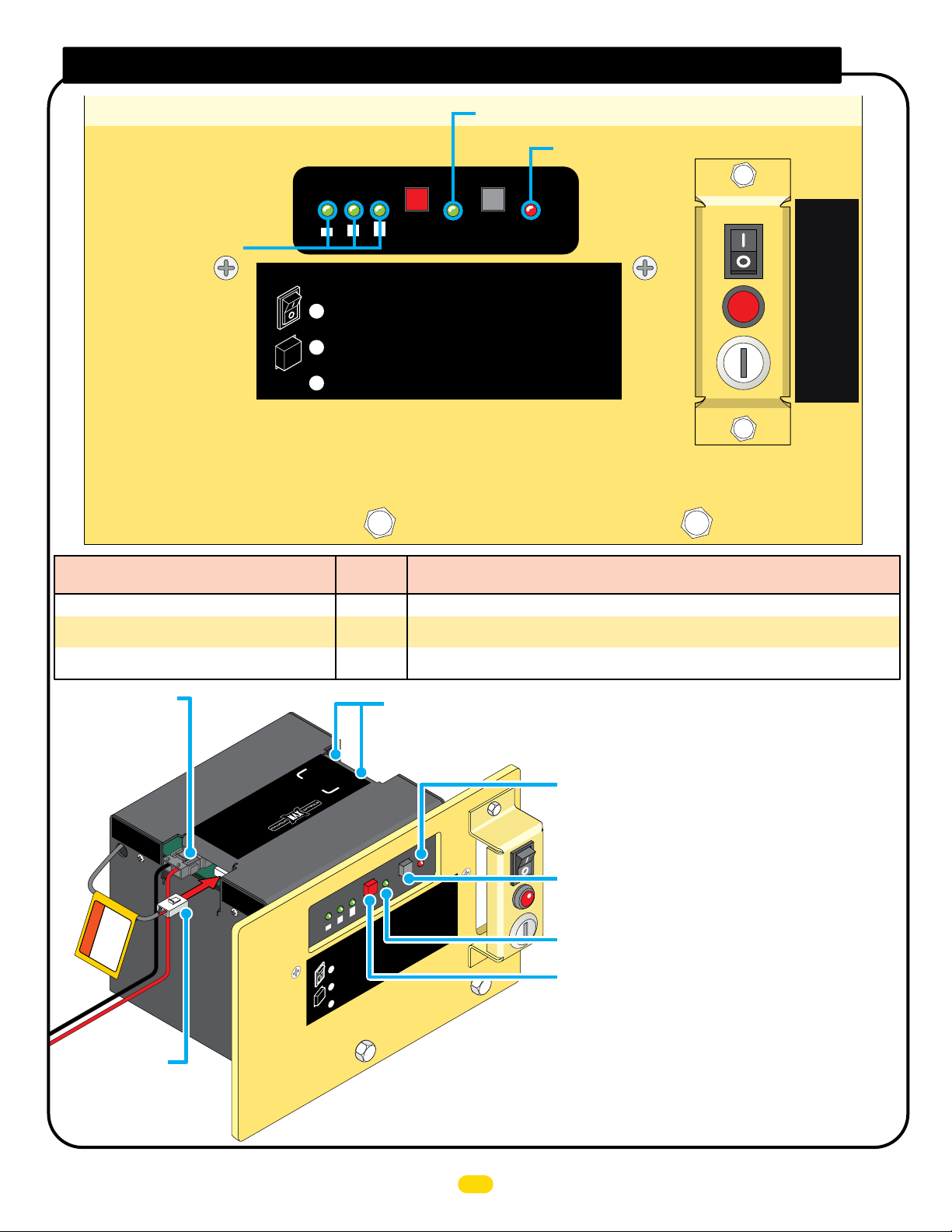
BC-7 module LED troubleshooting
2. REPLACE BATTERY
3. BATTERY IN ERROR
1. BATTERY VOLTAGE
POWER
N
O
OFF
ON/OFF
Battery
BC-7 LED
Problem Condition
“BATTERY VOLTAGE (E 1/2 F)” LEDs, only “E” is ON.
“BATTERY IN ERROR” LED is ON.
“REPLACE BATTERY” LED is ON.
TEST
Battery
MAX BC-7
Battery Module
Battery IN
Error
Battery Voltage
EF1/2
ON/OFF
Battery
Replace
Battery
To Turn OFF ALL POWER:
1 Turn OFF AC POWER switch on MAX Toroid.
Battery power remains ON.
2 Press and HOLD ON/OFF BATTERY button on
MAX BC-7 until 4 LEDs turn ON, release button.
3 WAIT for ALL LEDs to turn OFF. Up to 30 sec.
Normal
LED
1
OFF
3
OFF
2
• Battery is very LOW. Check if AC power ON/OFF switch is ON. If so, check AC power.
• “BATTERY Plug” not plugged in to “BATTERY IN” port on battery module (see below).
• Battery needs to be replaced if BATTERY TEST fails and “REPLACE BATTERY” LED is ON.
Solution(s) for
Problem Condition
GATE
SHUT
OFF
RESET
GATE
OPEN/
CLOSE
POWER/SOLAR IN Port:
MAX Megatron Toroid
box connection.
POWER/SO
LA
IN
R
IMPORTANT
ore use
connect to
f
be
“BATTERY IN”
BATTERY Plug:
MUST be plugged
into “BATTERY IN”
port Before use.
POWER IN / Battery Pack Ports:
Back of MAX MC-200 motor
controller connections.
ER
POW
IN
y
R
er
t
E
t
LL
Ba
Pack
TO MOTOR
S.com
U
w.Max.
w
w
R
LA
SO
ER/
N
I
POW
BATTERY
BATTERY
IN
N
I
CONTRO
attery Vo
B
EF1
O
OFF
e
ltag
epl
R
e
g
Batt
OFF
/
/2
Volta
y
ON
F
er
ry
t
e
t
t
Bat
Ba
ON/OFF
E1/2
Batter
urn OFF ALL POWER:
AC PO
er r
FF
To T
w
O
R
rn
Tu
ery po
t
t
1
POWE
Ba
ntil 4
u
N
ess and HOL
Pr
2
AX BC-7
M
for ALL
F
WAIT
3
y
OF
r
/
e
tt
ON
a
B
ac
er
L
e
y
y
WER sw
ma
e
ON/
D
EDs
AX BC-
M
tte
Ba
Batt
Er
TEST
y
er
Batt
T
e
c
Ba
la
p
y
Re
r
tte
Ba
c
it
N.
O
s
in
F BATTERY
F
O
turn ON, release but
OFF.
EDs
n
L
o tur
t
7
Module
ry
C-7
e
l
B
X
Modu
A
M
tery
t
Ba
y IN
er
r
o
r
ry IN
e
tt
Ba
rror
E
ST
E
ry
e
tt
id.
o
r
o
T
MAX
n
n
.
o
h
ton
button o
.
c
e
s
0
3
to
Up
Battery IN Error LED: Lights when there is a battery
connection problem. Make sure battery plug #1 is plugged
into BATTERY IN port or there is no damaged or loose wires.
TEST Battery Button: Press to show amount of battery power
available when using battery power ONLY (Battery voltage
LEDs will light respectively).
Replace Battery LED: Replace battery when lit.
ON/OFF Battery Button:
IMPORTANT: Battery power automatically turns ON when MAX
Megatron Toroid Box AC POWER Switch is turned ON.
To turn OFF ALL POWER to operator:
1. Turn OFF AC POWER Switch on MAX Megatron Toroid Box.
Battery power remains ON.
2. WAIT for 15 seconds.
3. Press and HOLD (approx. 5 seconds) the RED ON/OFF BATTERY
button until MAX BC-7 LEDs turn ON, then release button.
LEDs will turn OFF. (Up to 30 sec.)
UL 325 2016 Standard-MAX Quick Install Rev 8
20
Page 23
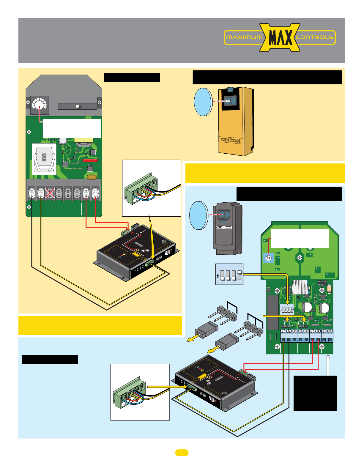
Commonly used
G
N
D
1
2
3
G
N
D
1
2
3
Safety Sensor
Wiring
Installation Steps:
1. Set switch to “LIGHT ON”
2. Wire 12V power to photocell
3. Wire motor controller EDGE 1
to photocell NO1
Wire motor controller GND to
photocell C-1
4. Align photocell to reflector
5. Adjust sensitivity
Jumper UNUSED Entrapment
Protection Inputs or a fault
will occur.
OK to
2
3
Edge 2
Photo
Cel
l
-
-
ND
G
(-)
)
(+
485
RS-
-
-
GND
PWR 12V
RM
on
V
ti
12
otec
r
WR
P
200
d
pment p
e
C-
ra
us
M
th
be
T
ensor Gu
Entrapme
US
S
M
so
12V
en
s
er
A
PWR
•
op
00
•
d
re
g
o
n
t
e
ni
Mo
Edg
Reversi
OR
Mon
E
C
dg
LOS
d
e
e
t
E
ON
1
ica
LY
ON
Ed
be
detected
n.
ILL
i
Pho
W
m
Edge
5
de,
dual
o
in
to Cell
en
m
n
wh
r
with
a
in
.
d le
d.
D
n
n aga
en
o
d
RE
t
t
n
u
tio
a
TO
rs
NI
O
umpe
j
M
npu
i
ow
ST
stops.
n
t Protec
U
e
r
sed
n
M
a
:
s
me
unu
p
ut
p
tra
In
n
e
E
g
d
E
l
l
e
2
C
to
Pho
1
MATR
e
g
O
Ed
L
U
p
a
r
WER
t
n
E
PO
r
e
l
0
l
0
2
-
C
r Contro
M
to
o
M
EDGE 1
GND (Com)
GND
1
GND
Edge 1
24V
R
W
P
RS-485
1
IX
MATR
n
1
tio
s
tec
ro
EDGE
o
t
t P
ideline
d
n
on.
i
t
(N
re
D
wi
func
e
SE
b
O
OT
ONL
ST
N
s
CL
r
o
MU
s
LY
r
n
when
L
A
se
00
or WILL
2
at
C-
ORM
nd/
M
N
a
ORED
s
re
IT
or’
dge
Wi
at
E
ed.
MON
er
ANY
g
us
n
i
o
op
t
rs
d
e
are
WR
v
re
P
i
e
w
ONITORED
R
00
•
M
be
er
d
MC-2
w
e
S
•
po
U
or
l
it
N
hoto
U
P
•
Cel
JU
Jo
g L
Jo
g RT
T
GN
-
g
D
-
e 1
-
2
1
2
3
r
ts
Jog LT
Jog RT
SW
imit
L
Edge 1
GND
Edge 2
Photo
Cell
IX
E
N
I
-L
N
or
)
h
.
rs
C
o
.
eac
at
r
o
t
,
ope
Y
l
ua
d
uts.
hoto Ce
p
P
n
I
or
3
T
he
t
S
of
MU
se
12V
or
inputs M
D
E
ERED
P
M
O
EN
CAUTI
T
AT
JOG
LEFT
use
12VDC
PWR 12V
Polarity does NOT matter
GND
Power In
e “LEA
b
.
T
MOTOR
:
rs
US
M
&
2
3
senso
&
R
nso
2
Se
s
BE
D
NITO
N inputs
ut
p
O
RE
M
In
nputs
y unused
TO
i
o
t
n
o
t
A
o LEAR
.
ONI
T
.
d
M
ed
.
n
1
re
ar
pe
wired
m
le
versin
r
ju
Re
2.
be wi
Press
3.
bu
MC-20
AR
Y motor controller
al opera
tors are used
LA
A
T
I
M
CH
LI
IT
W
S
Y
R
E
T
K
nt
BAT
e
PAC
wi
s
R
ower
p
S
sor
TO
O
Y
M
PUT
sen
IN
ONL
C-2
M
”
D
NE
R
e
b
e
be
T
T b
3
US
ey can
US
can
M
h
M
l
t
s
r
uts
p
OP
n
1
i
FORE
oto Cel
s.
x
h
ST
in
P
eg
/or
b
Matri
e
ut 2 or 3.
and
on
od
OPEN &
np
e
e
m
e
r i
g
h
t
tim
rn
the
e
ea
g Ed
l
LD
m
,
a
to ei
TION
d
s
O
r
HO
d
E
M
e
d
S
R
the
O
O
L
hea
T
nd
C
i
an
O
is
.
M
p
in
P
ns at
o
m
O
ee
tt
b
5
ST
til
or
N
r each
E
un
sts f
o
f
la
OP
LEDs
e
.
d
ON
0
.
o
e
b
m
20
00s
n
L
ping
C-
r
2
-
a
e
IL
M
ee
b
n
W
o
s
MC
Le
are us
b
ED
TH
by
sor
L
rs
4.
BO
to
TOP
r
a
r
enso
sen
o
S
e
s
s
f
s
e
arn
op
ng
Pr
le
i
.
p
5
o
t
e
uts
be
p
In
0
.
Sensor
Wire
n
l ca
l
o
t
d
D
N
G
1
use
2
e
.
b
3
rs
o
n
ns
.
r
u
.
remai
cc
T
o
ons
i
t
ill
US
w
lati
ruc
lt
t
s
al
t
au
n
i
f
ins
n
’
o
d
i
t
a
l
ce
i
al
not
nst
i
a
r l
ee
13
S
Voi
14
N:
15
ION:
16
T
X
3
4
5
MA
LED ON
ERD
tivity
Sensi
T
JOG
RIGH
Min Max
SENSITIVITY
Sensitivity Adjustment:
If the photocell does not respond to an
obstruction, lower the sensitivity by
turning adjustment counter-clockwise.
C-1 NO1 NC1
1
2NO3
Com
NC
EDGE 1 to NO1
DO NOT connect
to NC1 #3.
N01
C-1
NOTE: DO NOT
use 10K Resisitor
included with
photocell.
Set switch to
“LIGHT ON”
LIGHT ON
456
Use PRIM
whe
DARK ON
Power
24 to 240 VAC
24 to 240 VDC
n du
IMPORTANT: Photocell MUST be powered by MAX
Motor Controller or it will NOT be MONITORED.
NOTE: To meet the UL 325 2016 standard, Type B1 Non-Contact sensor
entrapment protection device MUST be MONITORED by the gate operator.
Installation Steps:
1. Set DIP-switches
2. Remove jumpers JP-5 and JP-6
3. Wire 12V power to photocell (VRX)
4. Wire motor controller EDGE 1
to photocell NC (Energized)
Wire motor controller GND to
photocell COM (Energized)
5. Align photocell to reflector
6. Adjust sensitivity
Jumper UNUSED Entrapment
Protection Inputs or a fault
will occur.
G
ND
1
Cell
2
3
Edge 2
Photo
GND
Edge 1
Sensor
Wire
www.max.us.com
omron E3K-R10K4
Photocell (Reflector)
CLOSING Direction
NOTE: To meet the UL 325 2016 standard,
Type B1 Non-Contact sensor entrapment
protection device MUST be MONITORED
by the gate operator.
IMPORTANT: Photocell MUST be in alignment with
reflector or fault will occur.
emx irb-ret
Photocell (Reflector)
CLOSING Direction
Sensitivity Adjustment:
M
C-
200 S
l
i
de
n.
o
D
ER
12
r
Moto
OverLoad
DIP-Switches
1 - OFF
O
1 2 3 4
2 - OFF
N
3 - OFF
4 - ON
NOTE: Power must be cycled
when switches are changed.
JP-5
10K
JP-6
4W
PO
MC
Moto
-
E
Ph
o
to
Ce
WER
2
00
U
r
L
C
En
ont
tra
r
olle
r
Le
by
4.
b
LE
e
s
D
e
s
n
f
o
W
s
r
o
B
o
r
5
p
o
O
.
e
P
n
ra
TH
r
M
e
t
to
o
s
M
rs
s
l
b
e
C
ST
e
a
a
e
I
rn
r
n
e
p
OP
p
i
s
n
u
u
e
g
s
t
b
s
n
s
u
s
ar
t
o
t
o
t
r
o
e
p
s
n
s.
n
a
o
n
w
d
MON
e
n
t
r
ap
I
T
OR
Inp
me
ED
u
n
t
t
s
:
P
M
r
o
unu
U
t
S
e
T
c
se
t
j
u
io
d
mp
n
i
n
er
p
u
ts
ll
Ed
g
3
e
L
imit
SW
2
1
Ed
p
g
e
MAT
O
RIX
N-
LI
NE
Cell
Photo
Edge 2
GND (Com)
3
.
P
bu
t
un
t
i
l
be
a
rn
O
PE
m
e
o
NS
p
d
i
e
n
g.
l
a
TO
I
sts
L
L
f
be
o
r
C
5
O
-2
N
0
-2
f
0
o
0
.
r
0
L
e
s
ED
a
e
ch
w
d
s
.
h
en
W
I
a
L
d
g
u
L
a
a
i
l
n
n
w
d
i
l
t
ea
h
i
n
r
n
5
m
m
o
i
n
d
.
.
e
,
Pho
t
o
Cel
E
d
g
l
e
g
2
e
1
ND
2
1
-
-
Edge 1
Jog RT
GND
Jog LT
EDGE 1
2
.
R
e
b
e
w
r
e
s
s
t
a
o
n
s
a
t
e
p
i
s
h
MO
T
P
C
L
mi
n
.
i
n
d
e
t
e
ct
ed
b
e
O
N
Ed
G
o
g
RT
L
T
-
Jumper
1
.
w
i
r
l
e
a
j
rn
u
m
p
e
ve
r
e
r
s
i
i
n
r
e
g
d
to
n
e
d
i
t
H
OL
t
he
D
s
a
ea
m
e
r
d
,
OR
l
e
a
M
OT
I
O
N
O
S
E
d
i
ca
t
e
d
e
1
J
Jo
g
JO
G
L
E
F
T
Remove B
M
OTOR Power
In
p
t
u
o
t
M
s
T
o
O
2
N
L
&
EA
IT
M
3
O
O
RN in
R
MUST
N
sen
I
e
T
d
OR
p
t
o
so
u
ed
ED
b
i
t
n
s
e
r
.
p
s.
Any
ut
S
“
2
L
e
s
d
&
EA
n
.
B
so
u
E
n
3
RNED”
rs
F
used
Edge
:
O
MU
R
E
inp
ST
a
t
h
h
n
e
u
e
b
d
r
t
y
s
e
/
i
o
n
MU
c
r
p
an
t
ut
Ph
h
e
ST
b
2
o
O
e
t
o
o
t
b
PEN
r
i
me
C
e
3
e
.
l
l
on
rn
&
ca
m
ST
Ma
n
o
O
d
t
r
e
P
i
x
b
e
1
g
i
n
s
.
C
L
OSE ONLY
Edg
M
o
R
n
ev
it
o
ersi
re
Edg
n
g
e
OR
M
o
n
i
t
o
Ph
re
d
o
t
C
o
•
R
el
ev
l
be
•
w
M
C-200
pow
•
U
er
NU
JU
M
O
S
M
E
NI
P
D
E
C
i
R
n
A
p
E
U
ut
A
D or f
T
T
I
T
ON
EN
au
:
T
S
I
ON
ee
i
:
nst
Voir
al
lati
l
a
on
not
i
nst
i
ce
d’
i
n
s
t
M
al
AX
L
E
D
O
15
JO
16
N
14
G
R
13
I
G
H
12
T
3
4
5
E
ER
Se
Mo
D
n
s
Ove
itivit
y
OTH Jumpers
r
Jumpe
I
n
M
OT
I
NP
OR
UT
S
B
ATTE
PAC
R
ON
Y
K
LY
LI
SW
MIT
p
sen
o
I
T
w
C
H
er
so
MC-200
rs
e
n
trap
w
i
th
men
P
MC
W
-20
R
t p
12V
ro
0
P
W
M
R
U
S
T
be
d
u
sed
E
•
n
A
t
s
r
o
en
a
S
per
p
•
e
s
m
W
or
n
a
t
i
s
e
or
re
M
M
o
n
W
O
U
N
r
o
t Pro
N
S
pera
OR
Gu
I
T
L
I
a
T
L
re
be
O
M
id
t
N
RE
or
used.
A
O
w
e
L
’s
i
T
li
D
re
L
ersi
MC
n
Y C
f
s
d
u
ensors
nc
t
i
ng
-
o
red
L
200
t
O
ED
i
o
E
SE
n.
t
dg
o
w
O
D
A
hen
e
P
N
N
(N.
and/
W
LY
Y
R
dual
C
,
o
to
f
or
12V
.
)
TO
t
he
eac
Phot
oper
RE
MU
3
h
I
s
D
at
o
npu
S
M
ors
C
s
T
en
U
ell
be
t
s.
ST
s
l
can
ors.
t
used t
wi
re
l
m
l
oc
ai
o
n
c
ur
.
3
G
2
N
1
D
ru
ct
i
o
ns.
l
at
i
M
on.
C
-2
00
S
l
i
de
MC-200
R
D
t
o
r
rLoad
Use PRIMARY moto
when du
Polarity does NOT matter
AL
ARM
-
-
t
-
ect
i
-
o
ND
1
n
V
2V
G
12
-
R
(+) -
)
5
(-
-
8
4
5
PW
8
-
ND
-4
V
RS
G
RS
MA
R 24
TR
PW
IX
t
1
e
c
t
io
e
n
s
G
E
1
o
r
l operators
a
PWR 12V
If the photocell does not respond to an
obstruction, lower the sensitivity by
turning adjustment counter-clockwise.
SENSITIVITY
O
1 2 3 4
N
2W
10K
NC COM
ENERGIZED
NC
COM NO VRX VTXCE
GND
ontroller
d.
e
c
r
s
u
e
r
a
N.C.
Com
4W 2W
VRX
PULSE
OUT
Power NOTE: If
photocell does NOT
function using VRX
power input, connect
power to VTX input
instead.
UL 325 2016 Standard-MAX Quick Install Rev 8
21
Page 24
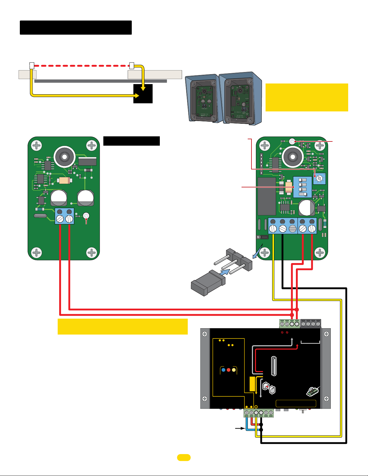
G
N
D
1
2
3
emx irb-mon
Photocell (Thru-Beam) CLOSING Direction
Single Gate Operator
Transmitter
(TX)
To Motor Controller
PWR 12V Input
Transmitter (TX)
TX
POWER INPUT
TRANSMITTER
BOARD (TX)
CLOSING direction Thru-Beam
Gate Closed
Installation Steps:
1. Set DIP-switches on receiver.
2. Install jumper on receiver.
3. Wire 12V motor controller
power to receiver.
4. Wire motor controller EDGE 1
to receiver photocell NC.
Wire motor controller GND to
receiver photocell COM.
5. Wire 12V motor controller
Green
LED
power to transmitter.
6. Align photocells.
7. Adjust sensitivity on receiver.
Receiver
(RX)
Operator
To Motor Controller
EDGE 1 and PWR 12V Input
Single
TX
RX
Sensitivity Adjustment:
If the photocell does not
respond to an obstruction,
lower the sensitivity by
turning adjustment
counter-clockwise.
DIP-switches:
1, 2, 3 are OFF.
Switch 4 is ON
If trouble occurs, try
turning switch 4 OFF.
NOTE: Power must be
cycled when switches
are changed.
Jumper MUST be on Com-NC.
NO
Com
NC
IMPORTANT: Photocells MUST be
in alignment or fault will occur.
Green LED will remain ON receiver
when in proper alignment.
Receiver (RX)
1 2 3 4
ON DIP
SENSITIVITY
NO NCCOM
NC
JUMPER
COM NORXPOWER
RECEIVER
BOARD (RX)
INPUT
EARTH
GND
Green
LED
IMPORTANT: Photocells MUST be powered by
Motor Controller or they will NOT be MONITORED.
NOTE: To meet the UL 325 2016 standard, Type B1 Non-Contact sensor
entrapment protection device MUST be MONITORED by the gate operator.
Jumper
MOTOR Power In
2 3
Inputs & MUST be “LEARNED”
to MONITOR sensors.
To LEARN inputs & :
2 3
1. MONITORED Sensors MUST be
wired to inputs BEFORE they can be
learned. Any unused inputs MUST be
jumpered.
2. Reversing Edge and/or Photo Cell can
be wired to either input 2 or 3.
3. Press and HOLD the OPEN & STOP
buttons at the same time on Matrix 1
until beep is heard, learn mode begins.
Motor Controller
MAX
MOTOR MOTION
OPEN STOP
Learn mode lasts for 5 min. indicated
by beeping.
4. LEDs WILL be ON for each detected
sensor on MC-200. LEDs WILL be ON
for BOTH MC-200s when dual
operators are used.
5. Press STOP button again within 5 min.
to learn sensors and end learn mode,
beeping stops.
Inputs are now MONITORED.
Entrapment Protection
Inputs:
unused inputs
Jumper UNUSED Entrapment
Protection Inputs to GND or
a fault will occur.
22
PWR 12V
Polarity does NOT matter
BATTERY
LIMIT
PACK
SWITCH
ONLY power entrapment protection
sensors with MC-200 PWR 12V
MC-200 PWR 12V MUST be used
Monitored
Reversing
CLOSE ONLY
Edge 1
Photo Cell
Edge 1
Edge 2
GND
23
1
CLOSE
MUST jumper
MOTOR
INPUTS
Common-GND
Normally Closed
Edge 1
-
-
ALARM
GND -
Entrapment Protection
Sensor Guidelines
A sensor MUST be wired to EDGE 1 or
•
operator WILL NOT function.
Wire NORMALLY CLOSED (N.C.)
•
MONITORED sensors ONLY, to each
Edge
operator’s MC-200 when dual operators
are used.
OR
Reversing Edge and/or Photo Cell can
•
Monitored
be wired to ANY of the 3 Inputs.
Photo
MC-200 PWR 12V MUST be used to
Cell
•
power MONITORED sensors.
UNUSED inputs MUST remain
•
JUMPERED or fault will occur.
Jog RT
Jog LT
CAUTION: See installation instructions.
ATTENTION: Voir la notice d’installation.
---
UL 325 2016 Standard-MAX Quick Install Rev 8
PWR 12V -
RS-485 (-) -
RS-485 (+) -
MATRIX 1
3
G
1
2
GND -
N
D
PWR 24V -
MC-200 Slide
Page 25
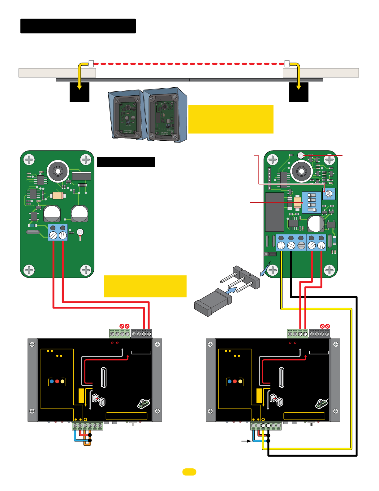
emx irb-mon
G
N
D
1
2
3
G
N
D
1
2
3
Photocell (Thru-Beam) CLOSING Direction
Dual Gate Operators
To Motor Controller
PWR 24V Input
Transmitter
(TX)
Entrapment Area
CLOSING direction Thru-Beam EMX IRB-MON Photocell
Secondary
Operator
NO Matrix 1
TX
Transmitter (TX)
TX
POWER INPUT
Green
LED
TRANSMITTER
BOARD (TX)
DO NOT wire Transmitter
(TX) to Secondary Motor
Controller PWR 12V!
BATTERY
2 3
MOTOR MOTION
CLOSE
MUST jumper
unused inputs
MOTOR
INPUTS
CLOSE ONLY
Photo Cell
Edge 2
23
MOTOR Power In
2 3
Inputs & MUST be “LEARNED”
to MONITOR sensors.
To LEARN inputs & :
1. MONITORED Sensors MUST be
wired to inputs BEFORE they can be
learned. Any unused inputs MUST be
jumpered.
2. Reversing Edge and/or Photo Cell can
be wired to either input 2 or 3.
3. Press and HOLD the OPEN & STOP
buttons at the same time on Matrix 1
until beep is heard, learn mode begins.
OPEN STOP
Learn mode lasts for 5 min. indicated
by beeping.
4. LEDs WILL be ON for each detected
sensor on MC-200. LEDs WILL be ON
for BOTH MC-200s when dual
operators are used.
5. Press STOP button again within 5 min.
to learn sensors and end learn mode,
beeping stops.
Inputs are now MONITORED.
Entrapment Protection
Inputs:
SECONDARY
Motor Controller
NOTE: To meet the UL 325 2016 standard, Type B1 Non-Contact sensor
entrapment protection device MUST be MONITORED by the gate operator.
Installation Steps:
1. Set DIP-switches on receiver.
2. Install jumper on receiver.
3. Wire 12V Primary motor controller
power to receiver.
4. Wire Primary motor controller
EDGE 1 to receiver photocell NC.
Wire Primary motor controller GND
to receiver photocell COM.
5. Wire 24V Secondary motor
controller power to transmitter.
6. Align photocells.
7. Adjust sensitivity on receiver.
IMPORTANT: Photocells MUST
be powered by Motor Controllers
or they will NOT be MONITORED.
PWR 24V
Polarity does NOT matter
-
-
ALARM
LIMIT
PACK
SWITCH
ONLY power entrapment protection
sensors with MC-200 PWR 12V
MC-200 PWR 12V MUST be used
Monitored
Reversing
Edge
OR
Edge 1
Monitored
Edge 1
Jog RT
GND
1
Entrapment Protection
Sensor Guidelines
A sensor MUST be wired to EDGE 1 or
•
operator WILL NOT function.
Wire NORMALLY CLOSED (N.C.)
•
MONITORED sensors ONLY, to each
operator’s MC-200 when dual operators
are used.
Reversing Edge and/or Photo Cell can
•
be wired to ANY of the 3 Inputs.
Photo
MC-200 PWR 12V MUST be used to
Cell
•
power MONITORED sensors.
UNUSED inputs MUST remain
•
JUMPERED or fault will occur.
Jog LT
CAUTION: See installation instructions.
ATTENTION: Voir la notice d’installation.
---
Jumper ALL Entrapment
Protection Inputs to GND.
GND -
PWR 12V -
RS-485 (-) -
RS-485 (+) -
MATRIX 1
2
3
GND -
G
N
D
1
PWR 24V -
MC-200 Slide
Gates Closed
IMPORTANT: Photocells MUST be
in alignment or fault will occur.
Green LED will remain ON receiver
when in proper alignment.
RX
Sensitivity Adjustment:
If the IRB-MON does not
respond to an obstruction,
lower the sensitivity by
turning adjustment
counter-clockwise.
Jumper MUST be on Com-NC.
Jumper UNUSED Entrapment
Protection Inputs to GND or
a fault will occur.
23
CLOSING direction Photocell
DIP-switches:
1, 2, 3 are OFF.
Switch 4 is ON
If trouble occurs, try
turning switch 4 OFF.
NOTE: Power must be
cycled when switches
are changed.
NO
Jumper
MOTOR Power In
2 3
Inputs & MUST be “LEARNED”
to MONITOR sensors.
To LEARN inputs & :
2 3
1. MONITORED Sensors MUST be
wired to inputs BEFORE they can be
learned. Any unused inputs MUST be
jumpered.
2. Reversing Edge and/or Photo Cell can
be wired to either input 2 or 3.
3. Press and HOLD the OPEN & STOP
buttons at the same time on Matrix 1
until beep is heard, learn mode begins.
MOTOR MOTION
OPEN STOP
Learn mode lasts for 5 min. indicated
by beeping.
4. LEDs WILL be ON for each detected
sensor on MC-200. LEDs WILL be ON
for BOTH MC-200s when dual
operators are used.
5. Press STOP button again within 5 min.
to learn sensors and end learn mode,
beeping stops.
Inputs are now MONITORED.
Entrapment Protection
Inputs:
MUST jumper
unused inputs
PRIMARY
Motor Controller
NO NCCOM
JUMPER
Com
NC
PWR 12V
Polarity does NOT matter
BATTERY
MOTOR
INPUTS
CLOSE
LIMIT
PACK
SWITCH
ONLY power entrapment protection
sensors with MC-200 PWR 12V
MC-200 PWR 12V MUST be used
Monitored
Reversing
CLOSE ONLY
Edge 1
Photo Cell
Edge 1
Edge 2
GND
23
1
Receiver
To Motor Controller
(RX)
EDGE 1 and PWR 12V Input
Primary
Operator
Matrix 1
Receiver (RX)
1 2 3 4
ON DIP
SENSITIVITY
NC
COM NORXPOWER
RECEIVER
BOARD (RX)
-
-
ALARM
GND -
Entrapment Protection
Sensor Guidelines
A sensor MUST be wired to EDGE 1 or
•
operator WILL NOT function.
Wire NORMALLY CLOSED (N.C.)
•
MONITORED sensors ONLY, to each
Edge
operator’s MC-200 when dual operators
are used.
OR
Reversing Edge and/or Photo Cell can
•
Monitored
be wired to ANY of the 3 Inputs.
Photo
MC-200 PWR 12V MUST be used to
Cell
•
power MONITORED sensors.
UNUSED inputs MUST remain
•
JUMPERED or fault will occur.
Jog RT
Jog LT
CAUTION: See installation instructions.
ATTENTION: Voir la notice d’installation.
---
UL 325 2016 Standard-MAX Quick Install Rev 8
EARTH
INPUT
GND
Common-GND
Normally Closed
Edge 1
GND -
PWR 24V -
RS-485 (-) -
RS-485 (+) -
PWR 12V -
MATRIX 1
G
N
D
1
2
3
MC-200 Slide
Green
LED
Page 26
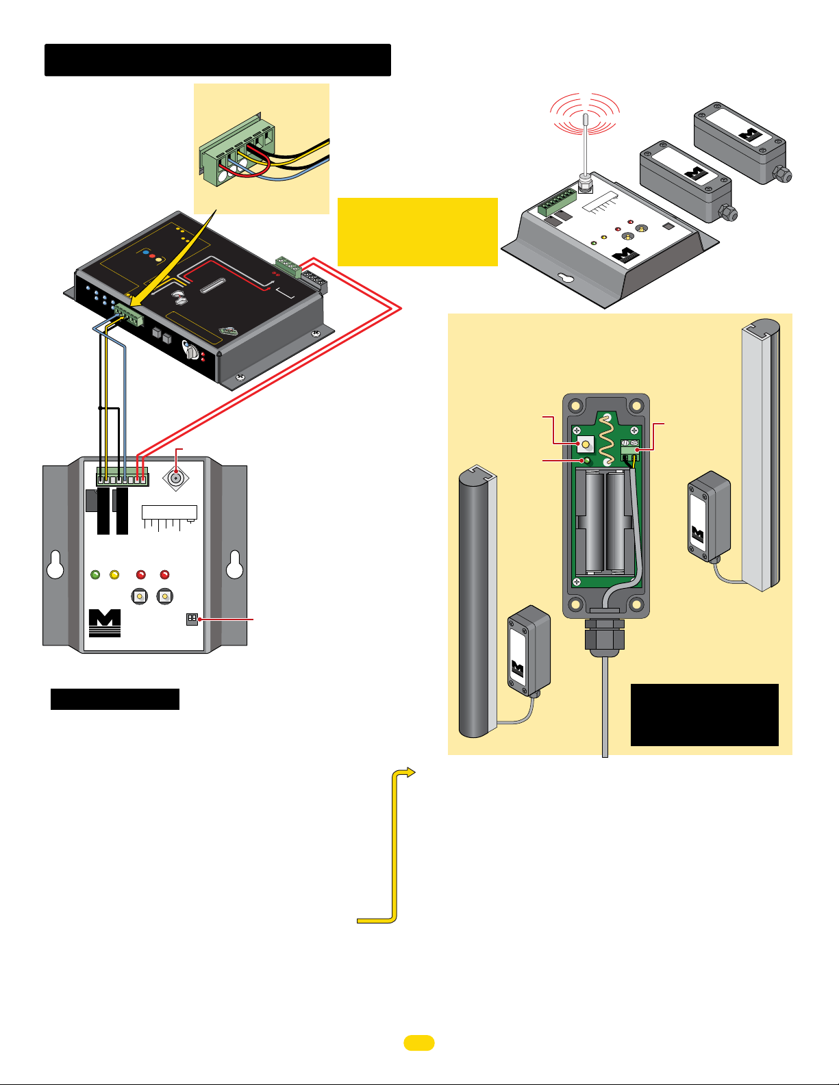
miller gate link
G
N
D
1
2
3
Jumper UNUSED Entrapment
Protection Inputs or a fault
MO
In
puts & MUS
to
MONIT
T
o
2
L
1.
EAR
M
3
OR sen
O
N
N inp
IT
OR
T
so
uts
be “LE
E
D
rs.
Sens
Any unus
2
&
BEFOR
ors
3
Edge and/or
:
M
ed inputs M
U
E
ST
they
be
D
can be
the O
Photo
US
T be
P
me on
Cell can
EN
& ST
n
m
Matrix
N
ode beg
OP
1
ins.
C
L
OSE ON
E
Rever
dg
OR
Monitored
Photo
Cell
•
UN
JUMPER
USED inputs M
C
AUTION
AT
T
ENTION
:
Se
e
installation instr
:
Vo
ir
l
a notice
MA
LED
X
ON
15
J
16
OG
RIGHT
3
4
5
ER
S
e
nsitivit
Antenna Mount
CH 2
10K
10K
COM
P/N.C.
CH 2
OUTPUT
P
12
R
will occur.
Photo
Cell
TO
RP
o
w
er
ARN
ED”
M
C-20
Mon
itore
s
d
ing
Edge
•
W
MONIT
o
p
er
ar
a
e
•
tor
used.
Reversing Ed
be wired
•
MC-200 PWR 12
po
we
to
ge
ANY of
r
MONI
TORE
V
ED
MU
D
or
sen
f
UST
ault will occu
rem
r.
d
uctions.
’i
nsta
lla
t
i
o
n.
14
13
e
12
ER
D
Motor
D
OverLoad
y
POWER
SELECT
Sensor
Wires
GND
1
GND
2
Edge 1
3
Edge 2
IMPORTANT: Receiver
MUST be powered by MAX
In
MO
I
N
TO
PU
R
TS
BATTE
PACK
R
ONL
Y
LI
Y
SWITCH
M
p
se
I
T
ower entrapmen
ns
o
A
r
s with
L
A
R
M
r
W
IL
00
whe
h
oto
n
pu
ts
u
se
d to
G
N
1
D
MC-2
U
ST
be
used
Ent
r
apment Protectio
Sensor
M
U
ST
be
L
NO
T funct
CL
OS
ED
ONL
n
dual op
Y
Cell ca
.
n
t prot
00 PWR 12V
ection
G
uidelin
wi
r
ed
e
to EDGE
s
i
o
n.
(N.C.)
1
,
to each
erator
s
MC-200
M
-
-
-
D
-
V
GN
-
)
-
(+
(-)
5
PWR 12
-485
D
8
4
-
RS
GN
S
R
M
A
TRIX 1
PWR 24
n
or
0
PWR
•
A
op
era
ire
NORMALLY
ORED sensors
’
s MC-2
a
nd
th
S
T
so
rs.
ain
2
00
S
l
id
12V
sensor
to
/or P
e
3 I
be
3
2
MC
-
NOTE:
Edge 1 - CLOSING direction ONLY
Edge 1 is automatically MONITORED.
Edge 2 - “Learned” Open/Close direction
See installation steps #10 note below.
CLOSING 10K sensing edge
connected to Channel 1 (Edge 1).
OPENING 10K sensing edge
connected to Channel 2 (Edge 2).
Channel 1 & 2 transmitters MUST be
programmed by receiver. See below and
Miller Edge Gate Link MGL-K20
instruction sheet for more info.
Both DIP-switches (Channel 1 & 2) to “R”
DO NOT set to “P” Pulsed
Motor Controller or it will
NOT be MONITORED.
-
-
V
To PWR 12V and GND
Polarity does NOT matter.
Example: Input 3 is
NOT used and MUST
be jumpered to GND.
ller
ed.
contro
r
s
wired to inputs
u
Learn
by beepi
4. LE
m
sensor
ode lasts for 5 min.
D
s W
for
ng.
operators are us
I
BOTH MC
LL
on
be
M
C-200.
ON
s ST
-200s
OP but
ed.
when dual
ton again
.
M
ONIT
within 5 min.
earn m
O
RE
D
.
P
rot
e
ctio
jumper
d
inp
n
Cell
ut
s
3
2
1
Cell
E
Photo
Edge 2
Edge 1
GND
Edge 1
P/N.C.
P/N.C.
jump
2.
R
eversing
be wi
3.
Pres
buttons at the
red to either input 2 or 3.
until beep is h
s and
eard, lear
M
O
T
O
R
O
P
EN STO
P
CL
O
SE
f
or each
LEDs
indicated
d
W
etected
IL
L
be
O
N
o
de,
L
Y
Ph
oto
Ed
Edge 1
ge 2
GN
J
og RT
D
-
-
-
Jog RT
Jog LT
JOG
LEFT
Edge 2
learned.
ered.
HOL
same ti
M
OT
IO
e
1
Jog LT
o
POWER
MC-200
Motor Controller
PhotoC
UL
En
I
En
t
r
Input
ell
trap
5.
Pres
to learn sensors and end l
beeping stops
nputs
are now
apment
s:
MUST
unuse
Edge
Limit SW
2
1
Edge
MATRIX
ON
-
LIN
MAX Motor Controller
Use PRIMARY mot
when dual operators are
GND
CH 1
Channel 1
Channel 2
COM
POWER
P/N.C.
STATUS
CH 1
LEARN
MGL-RX20
MillerEdge
Monitored Gate Link
MGL-RX20 Receiver
Installation Steps:
1. Set Both DIP-switches to “R” on receiver
2. Wire 12V power to receiver, polarity does not matter
3. Wire motor controller EDGE 1 to receiver CH 1-P/N.C.
Wire motor controller GND to receiver CH 1-COM
4. Wire motor controller EDGE 2 to receiver CH 2-P/N.C.
Wire motor controller GND to receiver CH 2 - COM
5. Install antenna on receiver
6. Install batteries in transmitters
7. Wire Channel 1 Transmitter to CLOSING Edge ONLY
8. Wire Channel 2 Transmitter to OPENING Edge
9. Program Channel 1 and 2 on MGL-RX20 receiver
10. Program MAX motor controller to “LEARN” Edge 2
NOTE: Edge 2 will function without being “Learned” but will NOT be
MONITORED by the MAX gate operator.
See your chosen Max operator manual to program the MAX motor
controller to “Learn” Edge 2 if desired.
2 Channel Wireless Communication
d
MGL-TX20
onitore
e Link
M
at
G
Second transmitter
sold separately
MGL-TX20
Link
e
t
Monitored
Ga
Transmit
2
R
CH
POWE
1
H
C
10K
N.C.
P/
COM
10K
N.C.
P/
2
COM
CT
T
E
CH
L
SE
EARN
L
MillerEd
L-RX20
MG
Monitored Gate
ge
OUTPU
P
R
1
CH
US
STAT
R
POWE
Link
e
g
d
MillerE
ter
Receiver
Wire 10K Edges
MGL-TX20
Transmitter
Test Button
Green LED
Channel 1
MGL-TX
Monitor
20
Gate Link
e
d
10K CLOSING Edge
M
iller
Ed
g
e
Mount on Gate’s
CLOSING side.
Gate Link Receiver/Transmitter Programming:
1. Make sure receiver and transmitters have power.
2. Green power LED stays ON; CH 1 red LED will be blinking on
receiver.
3. To enter Learn mode, press the CH 1 Learn button for 1 sec.
The red led remains ON and the amber status LED will blink.
4. Activate the transmitting edge, the red and amber LEDs will
alternately blink rapidly on receiver. Then the red LED will go out
and the amber LED will remain ON.
5. Channel 1 is now programmed. Repeat steps for Channel 2.
6. To start over or erase programming, press and hold both
LEARN buttons for 3 seconds. The LEDs will blink rapidly and
then go into “fault” mode. Repeat the programming steps above.
24
MGL-TX20
Terminal Block
Connection
Polarity does
NOT matter.
Channel
MGL-TX20
Monitor
Gate Link
e
d
Batteries
M
ille
r
E
dge
2
Mount on Gate’s
OPENING side.
An MGL-TX20 transmitter is
needed for each channel of
the receiver.
A GEM-104 module is NOT
needed for the sensing edge
when using a gate link
transmitter.
UL 325 2016 Standard-MAX Quick Install Rev 8
e
Edg
er
Mill
10K OPENING Edge
Page 27

UL 325 2016 Standard-MAX Quick Install Rev 8
25
Page 28
CONFORMS TO UL STD 325
UL CLASS - I, II, III, IV
CERTIFIED TO CAN/CSA STD
C22.2 NO. 247
www.max.us.com
SAFETY SENSORS REQUIRED
Version 8
Residential/Commercial
Brushless DC Slide Gate Operators
Made in USA
4009963
Maximum Controls LLC.
10530 Lawson River Ave
Fountain Valley, Ca 92708
Tel: (949) 699-0220
 Loading...