

Maximum Controls MAX 1500, MAX 2200, MAX F18 Installation Manual
Quick Install Guide for
MAX 1500 / MAX 2200
Slide Gate Operators
CONFORMS TO UL STD 325
UL CLASS - I, II, III, IV
CERTIFIED TO CAN/CSA STD
C22.2 NO. 247
SAFETY SENSORS REQUIRED
Version 8
Residential/Commercial
Brushless DC Slide Gate Operators
Made in USA
www.max.us.com
1
4009963
UL 325 2016 Standard-MAX Quick Install Rev 8
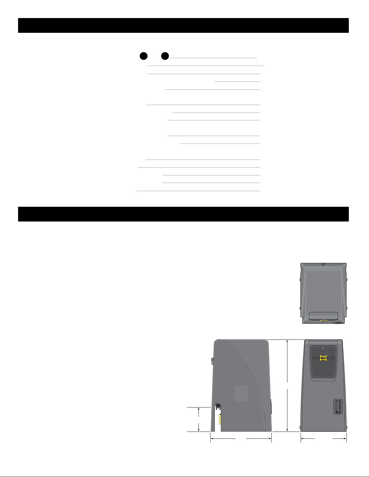
Table of Contents
Quick Install Guide
Installation Steps 1 thru 12
1 12
Gate Shut-Off Switch
Gate Tamper Feature
Dropping the Chain - Gate Tamper is Armed (ON)
Dual Gate Operators Wiring
Page
1-10
11
12
13
14
Troubleshooting
USB Black Box Port
Test Edge 1 Entrapment sensor
Gate Cycling Troubleshooting
Matrix 1 LED Troubleshooting
MC-200 LED Troubleshooting
BC-7 Module LED Troubleshooting
15
15
16
17-18
19
20
Commonly Used Safety Sensor Wiring
Omron E3K-R10K4
Omron IRB-RET
EMX IRB-MON Single Gate
EMX IRB-MON Dual Gates
Miller Gate Link
21
21
22
23
24
MAX 1500 / 2200 specifications
UL 325 Class of Operation - Class I, II, III, IV
Gate Type - Vehicular Slide Gate
Max Gate Length - 50 ft
Max Gate Weight:
• MAX 1500 - 1500 lbs Level Gate; 1000 lbs Uphill Gate - 5° Max
• MAX 2200 - 2200 lbs Level Gate; 1500 lbs Uphill Gate - 5° Max
Opening Time - Selectable speed control (MAX - 12 inch per second)
Cycles per Hour AC Power - Continuous
Battery Back-Up Cycles (Batteries fully charged):
• MAX 1500 - approximately 100 cycles
• MAX 2200 - approximately 100 cycles
NOTE: The number of gate cycles using ONLY battery back-up power will vary
depending on the weight of the gate, the gate length, the operating condition
of the gate, temperature and the amount of charge the batteries have at the
beginning of the battery power only operation.
Input AC Power/Amps - Switchable: 115VAC / 6 Amp, 1 phase
or 230VAC / 2 Amp, 1 phase
Motor:
• MAX 1500 - 1/2 HP 24VDC Brushless (6 million cycles)
• MAX 2200 - 1 HP 24VDC Brushless (6 million cycles)
Chain Size - #40
Operating Temperature: -4°F to 158°F (-20°C to 70°C)
Entrapment Protection:
- UL 325 Type A Inherent (ERD sensor)
- Inputs for NORMALLY CLOSED (N.C.)
UL 325 Type B1 (photo cell)
and Type B2 (sensing edge)
2
29”
7 1/2”
14 1/2”19”
UL 325 2016 Standard-MAX Quick Install Rev 8
Quick Install Guide
www.max.us.com
For detailed installation instructions and COMPLETE information about ALL the available options & features for
the MAX 1500/2200/F18, please refer to the MAX 1500/2200/F18 Installation and Owners manuals.
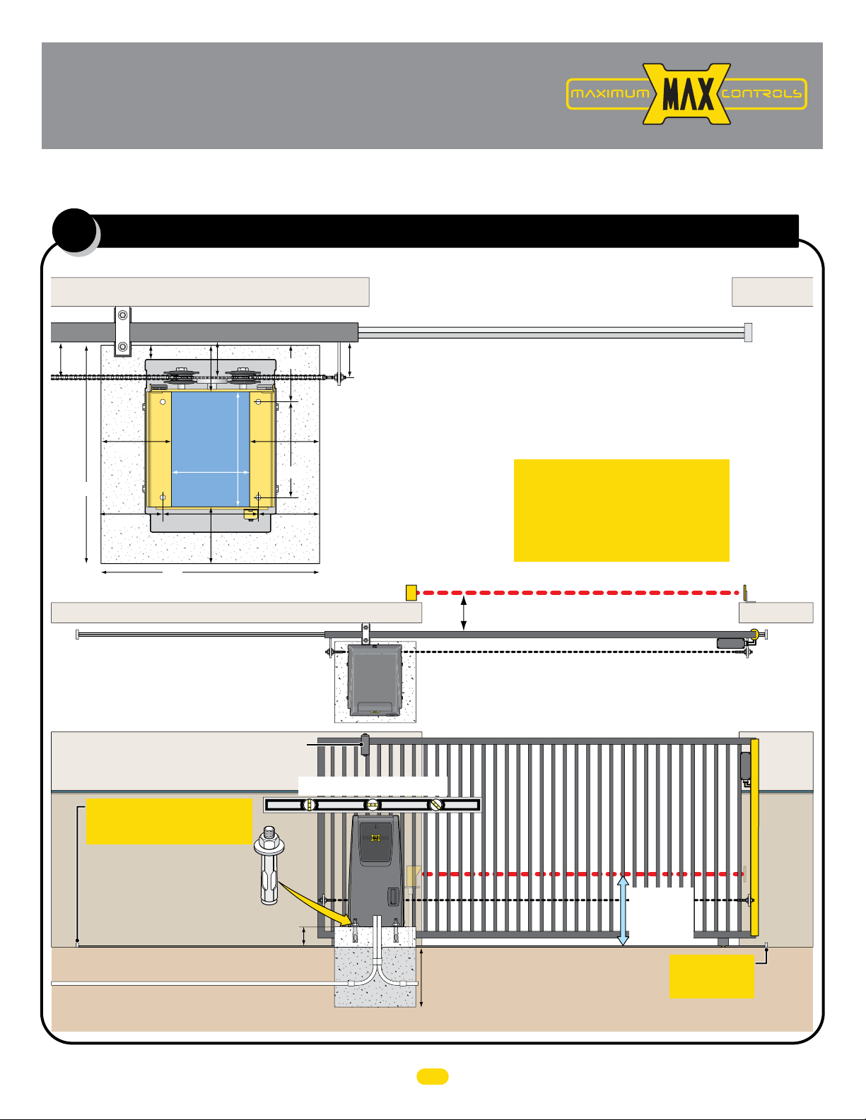
Operator Placement (standard)
1
The gate must be properly installed and work freely in both directions prior to installation of the gate operator.
Guide Rollers
24”
6.75”
Outside Property
1.5”
24”
Conduit
8.625”
10.5”
12.75”
Area
2” Gate Frame
4”5”
Cover
6.5”
6.2”
7.5”7.5”
10.5”
6.75”
Concrete Pad
Photcell to MC-200 EDGE 1 Input
4”4”
Operator
Position on
Concrete Pad
V-Rail
Conduit Guidelines and Suggestions
• REQUIRED - AC input power wire.
• REQUIRED - Entrapment protection CLOSING photocell and/or
sensing edge - when not using Gate Link wireless transmitter.
• In-ground loop wires.
UL 325 2016 Standard
ONE Entrapment protection sensor
MUST installed or operator will NOT
function. It MUST be MONITORED
and NORMALLY CLOSED (N.C.).
CLOSING Photocell Beam can be 5” or less away from gate
Physical Stop
Reflector
Gate in Closed Position
Inside Property
Operator in Front Position (Standard)
Note: See manual when mounting operator in REAR Position.
Guide rollers MUST be Installed to keep gate upright.
Operator MUST be level.
IMPORTANT: Physical stops MUST
be installed on BOTH ends of rail to
keep gate from traveling off of rail.
Secure gate operator to
concrete pad with four
(4) 1/2” x 3” (min)
sleeve anchors.
6” above ground to avoid flooding.
Input Power
Concrete Depth Note: The heavier the gate, the deeper the concrete pad should be. At least two feet recommended for heavier gate.
1/2
Conduit Run
Concrete Pad
Check local building
codes in your area for
depth of concrete
before installation.
Photocell
Beam Height:
21” Normal
27.5” Max.
MUST be installed
Wireless
Module
IMPORTANT:
Physical Stop
CLOSING
Sensing
Edge with
Wireless
Module
Wireless
Module
CLOSING
Sensing
Edge with
Wireless
Module
UL 325 2016 Standard-MAX Quick Install Rev 8
1
2
YES
NO
YES
YES
NO
NO
NO
NO
NO
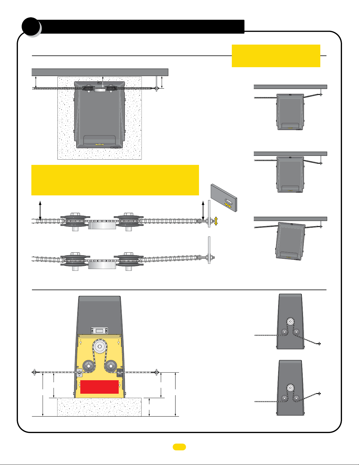
connect chain to gate
Top View of Operator
NOTE: 25 ft of #40 nickel plated chain included.
Minimum distance between the drive gear and gate is 4”.
4” Min4” Min
Drive
Gear
Chain
Bracket
YES
IMPORTANT: Operator and chain MUST be parallel to gate or the idler
wheels could fail. Use the “Fine Tune” adjustment on the gate bracket
connection bolt and make sure the chain runs through the idler wheels
without binding on the side chain guides.
YES
Side Chain Guide
Side Chain Guide
Idler Wheel
4” Min4” Min
NO
Gate Bracket
Fine Tune
Adjustment
IMPORTANT: Physical stops MUST be
installed on BOTH ends of gate rail to
keep gate from traveling off of rail.
NO
Operator is too far from gate.
Chain is NOT parallel to gate.
NO
Operator is too close to gate.
Chain is NOT parallel to gate.
NO
Operator is NOT parallel to gate.
Chain is NOT parallel to gate.
Back View of Operator
YES
Chain brackets MUST
remain same height as
idler wheels.
Chain
Bracket
Idler Wheels
Factory installed
position
Concrete Pad
Operator in Front Position (Standard)
Chain
Bracket
7.5”7.5”
6”
Note: See manual when Connecting chain
with operator mounted in REAR Position.
NOTE: The chain should
sag no more than one (1)
inch per 10 feet of travel.
Do not over tighten the
chain.
13.5”13.5”
2
NO
Chain
Bracket
DO NOT mount chain bracket too low on gate.
NO
Chain
Bracket
DO NOT mount chain
bracket too high on gate.
UL 325 2016 Standard-MAX Quick Install Rev 8
ac input power
W
A
RN
IN
G
HIGH
V
O
L
T
AG
E
A
T
T
E
NT
ION!
H
I
G
H
VO
LT
A
G
E
W
ARNING
HIGH
V
O
LT
A
G
E
3
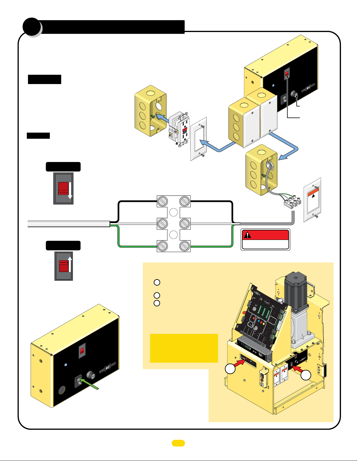
Choose either 115V or 230V setting on input AC power selector switch.
Wire desired input AC power wire to power terminal. A additional single gang box is provided to
install power outlets if desired. GFCI outlet type is recommended.
CAUTION: Make sure circuit
breaker is OFF from incoming
AC input wire BEFORE wiring!
Additional single gang box
provided. Wire GFCI outlet
to the input AC wire
BEFORE connecting to
operator power terminal if
power outlets are desired.
Input AC Power Options
CAUTION: If input AC power selector
switch is set for 115V but input power
is actually 230 V, 7 Amp Fuse will blow.
Single Phase 115VAC Only
115VAC
115V
Set to 115V
115 OR 230VAC
Power Wire
Single Phase 230VAC Only
230VAC
IMPORTANT: Make sure there are NO exposed bare
wires at the power terminal connection.
Chassis (Green)
Additional
Gang Box
Line (Black)
Neutral (White)
GFCI Outlet
NOT provided
Power Terminal
Line (Black)
Neutral (White)
Chassis (Green)
MAX
Toroid Box
AC
IN
Additional
AC
Power
Bo
Box
x
DANGER
HIGH VOLTAGE!
11
5
V
ER
OW
P
On
To
Off
AX
M
AC Power
Gang Box
Power
Terminal
Input
t
Selec
tage
Vol
AC or
5V
AC
11
230V
www.Max.US.com
FUSE
Amp
7
roid 15 Amp
7 Amp Fuse
Input AC Power
Selector Switch
WARNING
!
HIGH
LT
VO
sconn
di
power
icing unit
v
ser
E
AG
t
ec
before
Set to 230V
230V
Turn Power
ON
MAX
Toroid Box
AC
N
I
LEDs should light up on operator.
Battery power automatically turns ON.
Turn ALL Power OFF
1 Turn OFF POWER Switch on MAX Toroid Box.
Battery power will remain ON.
2 WAIT for 15 seconds.
3 Press and HOLD (approx. 5 seconds)
the RED ON/OFF BATTERY button until
MAX BC-7 LEDs turn ON,
then release button. LEDs will
turn OFF. (Up to 30 sec.)
t
pu
n
lect I
e
Se
g
or
Volta
AC
115V
5V
C
11
230VA
om
c
S.
.U
x
Ma
www.
FUSE
OWER
P
p
p
Am
7
MAX Toro
id 15
Am
n
O
Off
Turn Power ON
IMPORTANT: This procedure
must be followed whenever
ALL power must be turned
OFF on operator.
DO NOT
CYCLE
MC
Mo
3
OPERATOR!
3
MA
T
R
I
X
1
MA
B
AT
D
BACK-
E
i
T
n
E
USA
RY
U
P
M
ODE
LE
LE
AV
A
C
E
V
LO
E
O
SE
P
EN
D
P
RIM
OP
A
R
EN
G
Y
1
AT
A
TI
M
UT
E
E
OM
OP
EN
A
L
E
TI
F
T
C
OP
OP
AN
EN
R
EX
I
T
GH
TA
I
I
T
EN
T
IL
GA
M
/
AG
TE
C
L
L
O
OSE
O
CE
NT
E
R
SA
F
ET
Y
M
I
N
O
M
F
A
F
X
C
L
O
S
E
T
IME
ID
R
P
L
U
G
PA
RT
I
AL
O
P
E
N
12
V
D
C
G
N
D
P
O
SI
R
T
I
E
O
CO
24
N
V
R
D
C
DE
R
G
N
D
OBD
P
B
ORT
L
A
C
K
MAX
B
OX
G
M
IN
M
A
X
D
EPT
D
RADIO SIG.
R
RADIO GN
RE
D
I
F
E
L
/ RD
AX OPEN
D
GN
M
RIK
GN
D
PAD
Y
ST
M
GN
O
KE
P
N
R
I
GND
M
A
RY
GA
PHOTOCEL
T
E
GND
)
D
(+
GN
(-)
P
h
ot
oCe
P
OW
l
l
E
d
g
ER
e
Li
mi
t
-2
SW
2
00
t
o
UL
r
C
E
n
1
o
t
Ed
ra
n
p
t
g
ro
e
l
l
MA
e
r
TR
ON
I
X
-
L
I
NE
Cell
Photo
Edge 2
Edge 1
Jog RT
GND
Jog LT
J
OG
L
E
F
J
T
RI
E
1/
2
F
O
N
/O
F
Ba
F
Battery
t
Re
te
ry
pl
a
c
Ba
M
e
o
tt
d
e
u
ry
l
TEST
e
Ba
tte
PWR IN
ry
E
rro
r
D
N
OF
F
O
AT
E
SPE
LIMIT
SW
IT
O
C
N
L
INE
O
TO
R
LIN
E
SE
C
G
ATE
D
+)
(
GN
-)
(
MAX
LE
OG
GH
T
CK
E
OF
L
A
E
F
Y
X
C
IT
1.
ONTROL
5S
e
c
2S
e
c
MA
CEN
G
S
T
LO
E
R
CK
SAF
E
CO
TY
M
N
C
G
AT
E
TA
M
T
a
PE
m
p
R
e
r
N
O
CO
M
G
T
N
a
D
m
p
e
r
IN
PH
UL
MO
O
T
OCEL
T
O
R
MO
L
T
E
I
NT
O
N
R
E
AP
D
G
E
1
P
E
E
D
N
G
E
2
S
T
O
PCL
ID
PL
U
RE
G
E
O
VE
RROR
S
R
E
E
S
E
D
S
E
N
SITI
U
M
L
VI
OT
AL
T
O
Y
R
A
O
R
VER
ALAR
M
1
L
NO
O
2
A
LI
D
V
M
M
M
C
I
R
T
LAMP
OTOR
S
E
W
T
R
I
TC
E
S
S
LI
H
E
PP
/
T
I
NG
G
N
D
GAT
P
E
ower
S
T
A
H
TU
In
S
M
O
OT
I
P
N
OR
E
P
N
U
TS
C
O
B
A
M
T
T
CL
P
ER
A
C
OSE
Y
K
L
IM
S
W
IT
I
TCH
E
BA
A
L
T
A
T
R
E
M
R
Y
E
P
IN
U
SE
OPEN
M
STO
CLOS
PO
CO
GATE DISABL
D
O
1
1
5
N
6
14
1
3
1
2
3
4
5
E
R
ER
Se
Mot
D
n
si
Ov
ti
vi
ty
e
r
W
-
)
E
R
+
-
(
)
-
-
(
D
4V
2
GN
D
o
r
L
o
a
d
D
485
-
485
S-
V
GN
4
R
S-
2
R
M
R
A
W
T
B
R
P
O
I
ARD
X
put
t In
Selec
tage
or
l
C
Vo
A
1
1
5
V
5V
m
11
0VAC
.co
23
x.US
a
M
.
w
w
w
SE
U
F
ER
W
AC
O
P
IN
mp
n
p
A
O
7
m
A
5
1
ff
oroid
O
T
X
A
M
G
IN
RN
A
W
!
E
HIGH
N!
AG
O
I
T
t
L
O
e
r
V
TENT
onnec
fo
c
AT
is
it
be
d
un
!
g
in
power
ic
H
v
er
E
s
HIG
AG
T
r
he
nc
VOL
ra
nt
'b
a
en
e
i
t
d
av
e
r
t
n
'e
l
1
L
I
M
I
T
S
E
N
S
O
R
UL 325 2016 Standard-MAX Quick Install Rev 8
L
ground operator
WARNING
W
A
RN
I
N
G
4
Operator MUST be Properly GROUNDED
IMPORTANT: Operator MUST be grounded in lightning
prone areas or warranty will be VOIDED!
WARNING
connect chassis
to ground rod for
lightning protection
Proper grounding of this gate operator is a requirement for
LIGHTNING PROTECTION in lightning prone areas. To be effective,
ground connections should be made with a minimum 12 AWG, 600
volt insulated wire to a ground point within 3 feet of the gate
operator. The ground point must be at an electrical panel, a
metallic cold water pipe that runs in the earth, or a grounding rod.
Ground
within 3 ft
of operator.
Chassis
Grounding Rod
Ground
M
CO
AG
M
NC
OCK
LOCK
AGL
Y
A
M
ec
L
S
Y
2
DE
c
AR
e
S
5
IM
.
1
E
PR
T
F
F
O
GA
r NO
e
N
p
PE
M
m
T
a
O
T
H
CO
IG
Y
R
N
R
E
E
E
P
GND
O
OD
TT
T
BA
LEF
P M
U
E
V
N
A
E
E
BACK-
D
L
P
E
O
1
S
M
O
I
T
CL
1
IX
TR
A
VE
A
M
E
L
PEN
O
A
US
n
i
E
D
A
M
O
IC
T
A
M
TO
U
A
E
ANTI
T
A
G
TAIL
FF
O
N
O
T
XI
E
R
E
T
EN
C
Y
T
E
F
A
S
ID
G
U
PL
T
T
A
B
R
O
S
T
OT
U
P
M
N
I
n
I
r
e
w
o
WARNING
c
o
t
li
n
o
n
g
g
e
h
r
c
t
o
n
t c
u
in
nd
h
g
a
p
r
s
o
r
s
o
d
i
t
for
s
e
c
t
io
n
1
2
3
L
I
M
I
T
S
E
N
S
O
R
P
R
OTO
M
IN
r
e
ATE
LS
G
amp
T
R
O
E
PE
TR
AM
T
N
O
C
TY
E
E
L
F
S
SA
OCEL
LO
OT
/C
PH
N
E
P
XIT
E
N
I
F
F
M
O
OSE
CL
C
D
V
2
1
D
N
G
LIM
W
S
RY
V
E
4
2
K
C
A
P
G
1
R
E
DG
NTE
E
CE
2
GE
D
E
L
U
G
U
AP
PL
R
T
R
ID
N
O
E
ERR
V
2
1
T
E
ARM
R
AL
M
T
E
AR
UL
ES
AL
R
ND
G
N
O
I
T
O
M
R
O
T
O
M
AX
M
ER
IM
T
AL
I
T
R
N
PA
E
OP
SITIO
PO
ECOR
R
M
R
A
L
A
T
I
H
C
T
I
C
D
D
N
D
.
G
I
S
O
I
D
A
R
P
MC
ot
M
OPEN
SE
COM
O
CL
Y
T
P
CLOSE
I
V
E
O
T
TI
I
ST
S
N
GA
E
S
US
E
D
A
Y
N
RS
O
E
R
L
V
R
E
STAT
E
E
T
R
V
OPE
T
O
R
BA
/
O
T
H
O
C
T
M
IN USE
NG
I
SWI
P
T
P
D
I
L
MI
I
S
EE
L
AX
R
O
M
E
MP
N
SP
A
L
W
E
C
T
N
ER
D
T
OR
P
BD
BO
O
K
BLAC
PT
E
N
D
G
O
I
D
A
R
P
R
E
W
O
0
tr
20
n
-
r Co
o
PO
GA
E
L
-
B
V
N
-
4
MI
2
D
-
D
SA
R
N
)
I
-
G
W
(
-
N
P
V
)
AX
D
+
85
M
X
MIT
(
G
I
4
4
H
L
-
C
S
85
E
2
IT
4
X
R
E
I
-
W
N
T
S
S
R
D
LI
R
M
R
A
SE
AT
A
ON-
M
O
P
G
O
B
N
CO
O
OR
T
E
CL
NE
MO
P
C
LI
ST
-
SE
N
O
O
E
T
A
G
)
D
Y
L
(-
N
R
R
)
L
G
MA
I
R
D
E
E
P
(+
T
A
G
C
)
D
-
/ R
(
O
N
)
T
G
D
+
(
O
N
AD
D
G
PH
N
YP
KE
D
I
G
PEN
N
R
KE
O
T
G
D
S
X
N
A
D
G
E
N
M
R
G
I
F
Li
e
dg
E
ell
2
oC
hot
1
M
N
dge
O
E
L
U
ap
r
t
En
r
e
oll
D
R
E
3
2
1
1
4
1
r
5
o
1
ot
6
d
1
M
a
o
L
er
v
O
X
3
A
4
N
5
M
O
D
E
L
D
y
t
R
i
v
E
i
t
si
n
e
S
G
O
T
J
H
G
I
G
R
JO
T
F
E
L
Jog LT
Jog RT
W
S
t
i
m
Edge 1
GND
Edge 2
Photo
Cell
X
RI
T
E
A
N
I
L
-
e
l
odu
M
y
er
tt
Ba
N
I
y
r
e
t
t
a
B
or
r
r
E
T
S
TE
y
r
e
t
t
e
c
Ba
a
l
p
e
y
F
R
r
e
F
F
O
Batt
/
N
1/2
y
O
r
te
t
E
Ba
NOTE: Consult city codes for AC line wiring.
Beware of existing underground services.
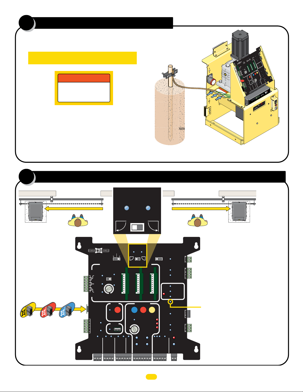
set opening direction and id plug
5
ID plug MUST be plugged in.
00
MAX 22
ID Plug
MAX 1500
ID Plug
MAX 1500
MAX 2200
MAX F18
ID Plug
Any of the THREE Chassis Grounds can be used. They are located next
to the gear reducer. DO NOT remove any existing green ground wires.
PRIMARY
GATE
OPEN
LEFT
OPEN
RIGHT
OPEN RIGHTOPEN LEFT
Set the desired opening direction.
MATRIX 1
MADE in USA
EXIT
CENTER
SAFETY
F18
MAX
PLUG
ID
12VDC
GND
24VDC
GND
RADIO SIG.
BATTERY
BACK-UP MODE
LEAVE
CLOSED
LEAVE
OPEN
OPEN
1 TIME
PRIMARY
OPEN
LEFT
GATE
OPEN
RIGHT
AUTOMATIC OPEN/CLOSE CONTROLS
ANTI
TAILGATE
OFFON
MAX
MIN
OFF
CLOSE TIMER
FIRE DEPT
RADIO GND
PARTIAL
OPEN
POSITION
RECORDER
OBD PORT
BLACK BOX
GND
MAX OPEN
STRIKE
GND
GND
MIN
MAX
KEYPAD / RDR
GND
OPEN
MAX
GATE SPEED
PHOTOCELL
GND
MOTOR MOTION
STOP CLOSE
REVERSE SENSITIVITY
LIMIT
SWITCH
ON-LINE
MOTOR
ON-LINE
PRIMARY
GATE
(+)
GND
(-)
SAFETYCENTEREXIT
MOTOR OVERLOAD
NO LIMIT SWITCH /
CLAMP SLIPPING
SEC
GATE
(+)
GND
(-)
MAGLOCK
OFF
OPEN
DELAY
STOP
2Sec1.5Sec
GATE
TAMPER
UL
ENTRAP
GATE
STATUS
CLOSE
COM
MAG
LOCK
PHOTOCELL
UL ALARM 12V
GATE DISABLE
COM
Tamper NO
COM
GND
Tamper IN
EDGE 1
EDGE 2
ID PLUG
ERROR
ALARM RET
RESET
GND
OPEN
CLOSE
BATTERY
IN USE
POWER
24V
GND
COM
NC
Dual Gate Operators NOTE: Secondary
operator will automatically be set to
the opposite opening direction as the
primary gate operator.
ID Plug Error: If ID plug is NOT plugged in,
board will constantly beep and operator will
NOT function.
NOTE: See manual for more
information about Matrix 1 settings.
UL 325 2016 Standard-MAX Quick Install Rev 8
4

install and adjust limit sensors
6
The limit sensor activators MUST be
installed on BOTH ends of chain to
indicate the OPEN and CLOSE positions
of the gate or DAMAGE will occur. They
will activate the corresponding LIMIT
SENSOR (Gray or Black) when they
move within range, stopping the gate at
the desired positions.
Back
View
Bracket
Plu
g
GRAY
Limit Sensor
Gate
LED lights when
sensing a limit
sensor activator
(Magnet).
Limit Sensor
Activator
(Magnet)
IMPORTANT: LEDs MUST light up when gate
reaches OPEN and CLOSE positions or operator
WILL NOT learn gate positions. If gate positions
are not learned, gate cycling speed will remain
slow during normal operation.
Limit Sensor
Activator installation
Gate
Plu
g
Plug
BLACK
Limit Sensor
IMPORTANT: Limit Sensor Activators
MUST be installed on BOTTOM of chain
Bracket
as shown.
Factory Installed
GRAY Limit Sensor
Limit Sensor
Activator
Note: See manual when installing limit sensors
with operator mounted in REAR Position.
JOG Left/Right Buttons on MC-200
PhotoCell
POWER
MC-200
Motor Controller
Push and HOLD the JOG LEFT or JOG RIGHT buttons
accordingly to move the gate (release the button to stop gate).
Operator in Front Position
(Standard)
Limit SW
UL
Entrap
Edge
2
1
Edge
MATRIX
ON-LINE
Jog RT
Edge 2
Edge 1
Jog LT
Photo
Cell
GND
JOG
LEFT
JOG
RIGHT
MAX
LED ON
Sensitivity
Factory Installed
BLACK Limit Sensor
Limit Sensor
Activator
14
15
13
16
12
ERD
3
Motor
4
5
OverLoad
ERD
Install Limit Sensors:
Use JOG Left/Right Buttons on MC-200 for installation
1. JOG gate to CLOSE position.
2. Mark magnet position on chain.
3. JOG gate open slightly and install magnet.
4. JOG gate to OPEN position.
5. Mark magnet position on chain.
6. JOG gate closed slightly and install magnet.
7. Gate positions can now be learned AFTER at least
ONE entrapment protection device has been installed
(see & ).
Breather Pin
7 8
CAUTION
OVE
EM
R
BEFORE
ATION
OPER
IMPORTANT:
Remove breather pin
from gear reducer
BEFORE cycling
operator.
UL 325 2016 Standard-MAX Quick Install Rev 8
5
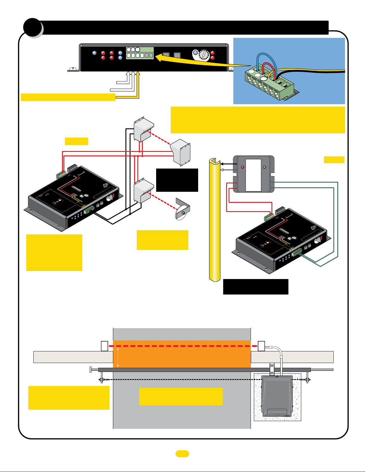
entrapment protection wiring
G
N
D
1
2
3
GN
D
1
2
3
7
PhotoCell
Edge
POWER
MC-200
Motor Controller
UL
Entrap
Edge
Photo Cell: LEARNED MONITORED OPEN/CLOSE
Edge 2: LEARNED MONITORED OPEN/CLOSE
EDGE 1: MONITORED CLOSE ONLY
Typical Wiring For:
Normally Closed (N.C.)
Photo Cell to EDGE 1
NOTE:
Matrix 1 MUST be
removed to wire
MC-200.
Power In
OR
be “
MOT
nsors
3
MUST
se
ts
&
R
2
O
s
IT
inpu
t
N
N
RED
npu
I
MO
nput
TO
i
to
o
t
o LEAR
T
d
d.
MONI
e
re
.
i
1
w
earn
l
umper
j
Rev
.
2
ALARM
CH
LIMIT
IT
SW
RY
E
T
K
t
C
AT
B
PA
w
er en
w
R
TO
sors
po
Y
L
MO
sen
N
INPUTS
O
MC-200 P
”
D
NE
R
EA
L
be
e
b
n
:
be
.
a
T
c
3
S
n
UST
&
ey
ca
M
h
t
MU
l
l
2
rs
s
e
o
C
P
s
n
o
O
nput
1
e
.
i
FORE
T
.
s
S
x
3
d
S
in
e
Phot
BE
tri
g
&
s
or
s
a
e
u
or
2
b
M
t
d/
EN
un
u
n
on
a
OP
np
i
e
Any
mode
ge
he
er
im
.
d
t
t
h
d
E
arn
e
eit
N
le
O
ng
,
o
ame
t
s
OTI
rd
HOLD
d
M
ersi
a
c
SE
he
re
i
t
O
di
nd
OR
he
t
n
a
w
CL
i
OT
s
a
i
.
s
e
M
s
p
b
re
ons
ee
t
min
P
t
b
TOP
5
u
3.
S
r
il
c
b
t
a
fo
n
e
u
s
t
r
s
o
f
la
ED
OPEN
L
.
ON
de
0
.
o
wh
e
0
s
g
b
m
0
-2
in
0
p
C
rn
d
LL
e
-2
e
I
M
s
ea
W
be
n
u
L
MC
o
s
y
r
re
u
b
D
H
o
a
b
T
LE
ns
rs
.
e
o
4
OP
s
BO
t
s
T
n
r
ra
e
o
S
e
s
s
p
f
s
st
o
rn
a
Pre
le
ing
.
p
5
o
t
e
s
t
e
u
b
p
n
I
IMPORTANT Sensing
devices MUST be
powered by MC-200
or they will NOT be
MONITORED.
me
p
ra
MC-200
h
it
d
e
t
a
c
e
t
de
h
LL
I
W
s
du
n
e
.
g
a
on
d
t
t
n
a
rs
o
.
s
p
w M
o
o
n
re
a
E
-
-
-
ectio
t
ro
WR
p
P
nt
MU
12V
WR
Monito
Rever
d
e
t
ON
e
b
l
min
a
5
in
h
mo
t
i
w
rn
n
i
a
lea
d
n
e
ORED
T
I
N
O
me
put
rap
n
I
nt
POWE
MC-200
Motor Controller
V -
-) -
GND -
(
5
48
-
RS
2V
1
RS-485 (+) -
ND
R
G
MATRIX
PW
n
12V
nt
ed
me
r
o
ap
be us
ns
T
ntr
e
S
E
S
MU
WILL
sensor
ator
A
N
•
oper
Wire
•
MO
operator
d
e
r
g
n
i
s
ed
Edge
r
OR
P
Monito
Edge
GN
.
Ph
Edge
,
e
d
oto
2
C
e
ll
.
n
o
3
er
p
cti
s
t
e
pu
jum
T
in
S
U
nt Prot
sed
M
:
nu
s
u
SW
t
Limi
ge
d
E
2
otoCell
h
X
P
1
ATRI
M
N-LINE
O
Edge
R
UL
trap
n
E
GND
PWR 12V
Polarity does NOT matter
PWR 24
1
or
1
E
s
ection
ot
ne
DG
i
E
.)
Pr
n.
idel
o
N.C
(
Gu
ncti
D
wired to
E
an
fu
T
be
c
NLY, to each
OS
O
L
ST
s
C
NO
MA
R
O
RE
TO
NI
are used.
Reversing
•
o
hot
Cel
Jog
Jog R
D
1
2
Photo
Cell
r
Y
hen dual operators
so
L
oto Cell
n
w
L
D
N
puts.
G
E
-2
ow
p
•
-
dge and/or Ph
ANY
P
00
MO
er
NUS
U
JU
Jog LT
Jog RT
1
In
2
3
be used to
T
n
of the 3
r.
MUS
sensors.
emai
cu
r
D
E
oc
o
12V
ST
R
OR
ucti
W
IT
N
install
on instr
or fault will
inputs MU
D
lati
E
ce d’
l
ED
i
R
nsta
i
MPE
ee
oir la not
S
V
:
:
15
ON
ON
16
TI
UTI
A
EN
C
TT
A
3
4
N
5
MAX
O
LED
ER
Sensitivit
JOG
RIGHT
JOG
LEFT
se
200
D
-
MC
’s
ired to
w
e
b
MC
•
l
L
T
T
-
-
1
Edge 1
GND
Edge 2
CLOSING Direction ONLY
NOTE: See manual for more information about
photcell and sensing edges installation and wiring.
Limit SW
23
2
1
MATRIX
ON-LINE
Cell
Edge 2
Photo
Recr
M
C-
2
00
Sl
i
d
e
ns.
ation.
ERD
3
2
1
1
14
d
Motor
Loa
Over
D
y
ND (C)
G
EDGE 1 (N.C.)
1
Jog RT
Edge 1
GND
Jog LT
JOG
LEFT
JOG
RIGHT
NOTE: See manual for more
information about learned
monitored inputs.
ONE Entrapment protection sensor MUST be installed or operator will
Thru-Beam
Power
Power
NOT function. It MUST be MONITORED and NORMALLY CLOSED (N.C.).
Power
Trans
See pages 21-23
for specific
photocell wiring.
Reflective
Beam
Reflector
IMPORTANT: Photocells
MUST be in alignment
or fault will occur.
MAX
LED ON
14
15
16
3
4
5
ERD
Sensitivity
13
12
ERD
Motor
OverLoad
Jumper UNUSED Entrapment Protection
3
2
1
hoto
P
Edge 2
EDGE 1
UL 325 2016 Standard
Typical HARDWiring For:
10K Edge
Normally
Closed
GEM - 104
ON = Obstruction
BLINKING = Fault
MON.
PWR
SAFETY
INPUT
GEM-104 MUST be used.
PWR 12V
Polarity does NOT matter
GND
R
TO
O
M
INPUTS
Power In
”
ED
RN
EA
OR
L
e
b
e
b
n
:
MOT
a
T
c
3
rs.
ST
&
ey
so
MUST be “
MUS
h
t
n
MU
2
3
rs
s
o
se
ts
s
&
put
u
R
n
t
n
p
2
e
i
FORE
O
S
d
s
IT
in
e
Pho
Sensing Edge
See page 24 to wire a Gate
Link wireless transmitter.
BE
D
N
s
N
r
u
ts
put
R
2
RE
t
d/o
In
MO
un
u
n
npu
TO
i
p
a
to
OP
n
i
o
e
t
Any
o LEA
e
r
g
.
T
d
h
e
.
d
d
t
h
d
MONI
e
E
re
.
it
i
e
1
r
e
g
w
e
o
p
t
earn
l
same
rsin
rd
HOLD
d
e
a
um
j
d
e
he
re
i
t
n
t
a
w
Rev
a
.
is h
s
e
M
2
s
s
p
b
n
e
re
o
e
t
P
t
b
.
u
3
il
b
t
n
u
Inputs to GND or a fault will occur.
Sensor Wire
GND
Example: Inputs 2 & 3
are NOT used and MUST
be jumpered to GND.
Normally Closed (N.C.)
Sensing Edge to EDGE 1
(CLOSING Direction ONLY)
V -
-) -
GND -
(
PWR 24
5
48
-
RS
1
-
2V
1
RS-485 (+) -
-
ND
R
-
G
MATRIX
PW
n
io
ALARM
ect
12V
IT
WR
H
P
IM
L
nt prot
ITC
me
SW
RY
E
T
rap
K
t
MC-200
C
AT
h
B
it
PA
be us
w
er en
ST
rs
so
MU
pow
Y
L
sen
N
12V
O
WR
P
MC-200
d
e
r
s
Monito
Rever
e
b
can
l
l
e
C
o
1
.
.
s
x
3
STOP
i
in
r
tr
g
&
o
e
b
Ma
EN
e
n
d
o
e
mo
im
t
rn
a
N
le
d
O
I
,
e
t
OT
a
M
c
SE
O
d
di
e
n
CL
i
t
OTOR
c
ON
.
e
n
t
e
b
mi
de
5
.
h
LL
r
n
I
c
i
l
o
a
f
W
m
,
e
s
e
s
t
5
r
dua
d
o
PEN STOP
f
in
n
ED
O
las
h
mo
L
e
it
.
ON
d
w
whe
0
rn
.
e
0
n
g
s
i
b
mo
0
lea
-2
a
in
.
0
g
p
.
C
d
rn
d
LL
a
e
n
-2
a
e
I
e
M
s
e
e
W
b
n
u
L
on
d
t
MC
o
t
s
y
n
r
ORED
re
u
b
D
a
H
o
a
T
b
I
E
s
rs
L
N
n
rs
.
o
e
o
4
OP
s
BOT
t
n
r
s.
ra
MO
e
s
o
ST
p
e
s
w
o
s
t
p
Prot
f
o
s
s
o
rn
n
a
re
g
P
re
le
nt
in
.
M
p
5
o
t
e
s a
t
e
u
me
b
p
n
I
puts:
rap
In
nt
E
h
P
R
E
POWE
MC-200
Motor Controller
or
on
1
cti
E
s
e
G
ne
D
i
rot
E
P
.)
n.
.C
idel
nt
o
N
(
ed
, to each
ncti
Gu
D
me
wired to
r
an
fu
o
SE
ap
be
c
NLY
O
tr
OT
ns
O
L
ST
n
N
e
s
C
E
S
MU
WILL
MA
tor
R
sensor
a
r
O
RE
A
N
•
ope
TO
NI
Wire
•
MO
operato
are used
g
n
•
i
dge
ed
E
r
o
hot
OR
P
Cel
Monito
Jog R
Edge
GN
D
Phot
Ed
1
ge
o
2
C
e
ll
2
n
3
er
p
ctio
ts
e
pu
jum
T
in
US
nused
u
SW
t
Limi
ge
d
E
ll
Photo
e
2
otoC
Cell
X
1
ATRI
M
N-LINE
O
Edge
UL
trap
n
r
.
Y
hen dual operators
so
L
oto Cell
n
w
L
D
N
puts
G
E
ow
p
-
dge and/or Ph
ANY
00
er
NUS
U
•
JU
Jog RT
1
In
M
2
3
C-
3
2
T be used to
0
0
n
of the
r.
MUS
sensors.
emai
cu
r
V
D
ns.
E
oc
o
12
ST
OR
ucti
ation.
MU
IT
PWR
N
MO
on instr
or fault will
inputs
D
lati
E
ce d’install
l
ED
R
E
nsta
i
MP
Jog LT
3
2
1
oir la noti
See
1
V
14
:
N:
15
O
ON
16
TI
UTI
Moto
EN
CA
TT
A
Over
3
4
N
5
MAX
O
LED
D
y
ER
Sensitivit
JOG
RIGHT
JOG
LEFT
ND (C)
G
se
200
D
-
MC
s
r’
.
ired to
w
Reversing
e
b
MC-2
•
l
Jog
L
T
T
-
-
1
Edge 1
GND
Edge 2
EDGE 1 (N.C.)
CLOSING Direction ONLY
Sl
i
d
e
ERD
r
d
Loa
Entrapment Protection Device Locations:
CLOSING Direction
Photocell
IMPORTANT: Entrapment
Protection Photocells MUST be
Monitored Normally Closed Type.
NOTE: Photo input on Matrix 1 is NOT
MONITORED (Normally OPEN) and is
NOT UL 325 entrapment protection.
Beam: 5” or LESS
from CLOSED gate.
IMPORTANT: Photocells MUST
be in alignment or fault will occur.
Outside Property
Entrapment Area
Gate Closed
Inside Property
Continued on next page.
6
CLOSING direction photocell
to MC-200 EDGE 1 input.
Run conduit to operator
Wall
UL 325 2016 Standard-MAX Quick Install Rev 8
continued
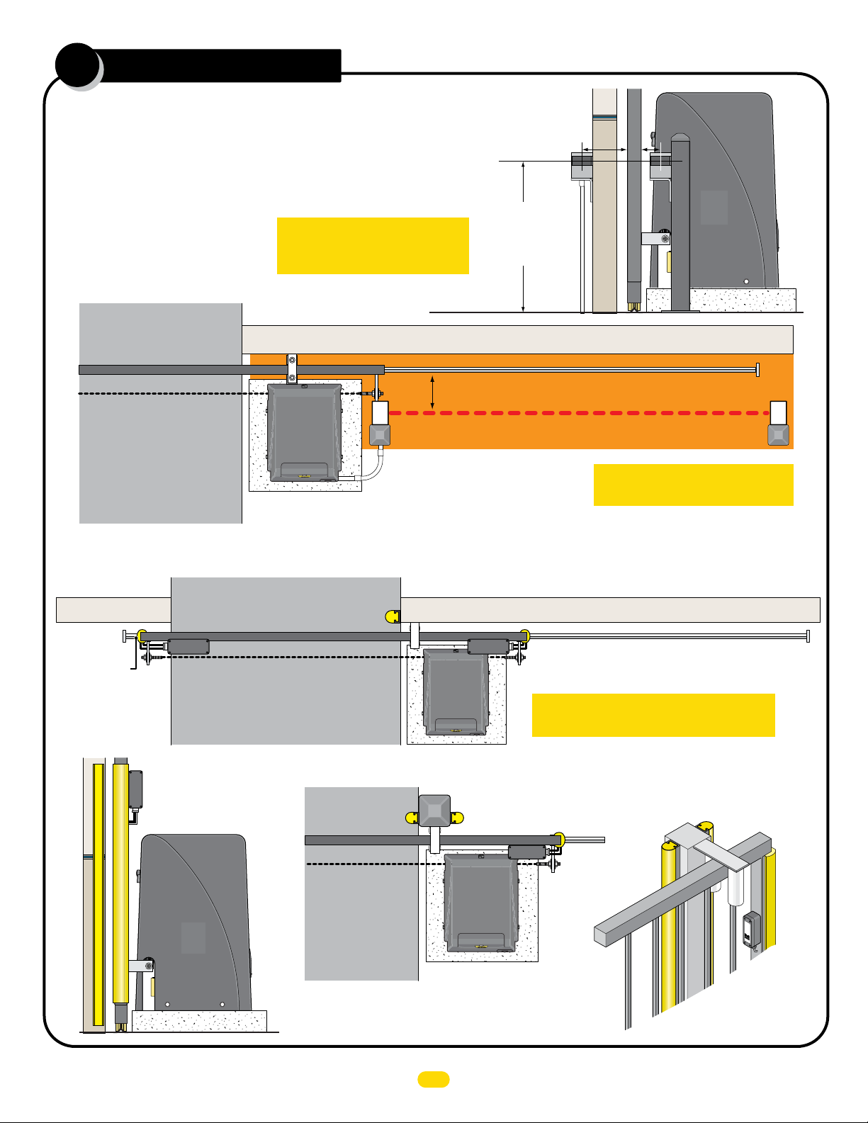
7
Entrapment Protection Device
Locations:
Photocell Beam Height
Install photocells on either side of
gate, as close as practical to the
gate but no further away than 5”.
Less
5”
or
Less
5”
or
OPENING Direction
Photocell
Outside Property
Gate Closed
Inside Property
Sensing Edges
Outside
Property
IMPORTANT: Entrapment
Protection Photocells MUST be
Monitored Normally Closed Type.
Beam: 5” or LESS from OPEN gate.
Run conduit to operator
OPENING direction photocell to MC-200
motor controller, Monitored. Normally
CLOSED (N.C.)
NOTE: Connect to Photo Cell input on MC-200.
Beam Height:
21” for most
installations but No
higher than 27.5”
above ground.
Wall
Entrapment Area
Inside
Property
Gate
Wall
Illustrations not to scale
Photo Beam
IMPORTANT: Photocells MUST
be in alignment or fault will occur.
CLOSING direction
10K NORMALLY CLOSED
Sensing Edge Wirelessly
Module
Wireless
Wall
NORMALLY CLOSED Sensing Edge
Wireless
Wireless Module
Module
WIRELESS NOTE: Refer to the
instruction sheet that comes
with the wireless module for
wiring and mounting instructions
when using wireless option.
OPENING direction 10K
Gate Closed
Wireless
Module
OPENING direction10K NORMALLY CLOSED Sensing Edge Wirelessly
IMPORTANT: Sensing edges MUST be
Monitored 10K Normally Closed Type.
Self-Supporting Post
OPENING direction
Sensing Edge
Gate Closed
If a self-supporting post is being used, then sensing edges need to
be installed on EACH side of the post to protect against entrapment
in the OPENING and CLOSING direction of gate travel.
CLOSING direction Sensing Edge
Wireless
Module
OPENING
direction
Sensing
Edge
Wall
OPENING
direction
Sensing
Edge
CLOSING direction
Sensing Edge
MGL-TX
M
on
2
0
ito
G
re
a
te
d
L
in
k
M
i
l
l
e
r
Ed
g
e
OPENING
direction
Sensing
Edge
(Wireless)
UL 325 2016 Standard-MAX Quick Install Rev 8
7
 Loading...