

Page 1
Installation Instructions
I. Introduction
Thank you for purchasing a Maximum Wireless Weather instrument. Maximum Wireless
Instruments are designed with the customer in mind. Ease of installation and operation enable
the “Do It Yourselfer” to install these instruments. If you need assistance, consult a contractor,
electrician, or satellite dish installer.
II. Components
Receiver Wind Tx Temperature Tx Rain Tx
III. Test Wiring
It is important to pre-wire and test operation from different locations prior to final installation.
A. Receivers
1. Merlin and/or Mystic
- Connect the AC power wires from the Receiver (Red and Green wires) to the
AC power terminals (polarity does not matter) on either Merlin or Mystic
instrument (Do Not apply power).
- Connect the White wire from the Receiver to terminal #1 (In) of the same
instrument.
- Connect the Black wire from the Receiver to terminal #2 (GND) of the same
instrument.
- The Yellow and Brown wires are used only if you are installing a Rainwatch.
- If both Merlin and Mystic are being installed, use the jumper wire enclosed with
Mystic for connection between these two instruments.
o Connect one end of the White wire to terminal #3 (Out) of the instrument
wired to the Receiver, and the Black wire to terminal #2 (GND).
o Connect the other end of the White wire to terminal #1 (In) of the second
Instrument, and the Black wire to terminal #2 (GND).
Page 2
A. Receivers (cont.)
2. Rainwatch
- Connect the Yellow wire from the receiver to terminal #4 of the Rainwatch.
- Connect the Brown wire from the receiver to terminal #5 of the Rainwatch.
B. Transmitters
1. Temperature
- The Temperature transmitter operates on two AA Alkaline batteries (supplied).
o Do Not install the batteries yet.
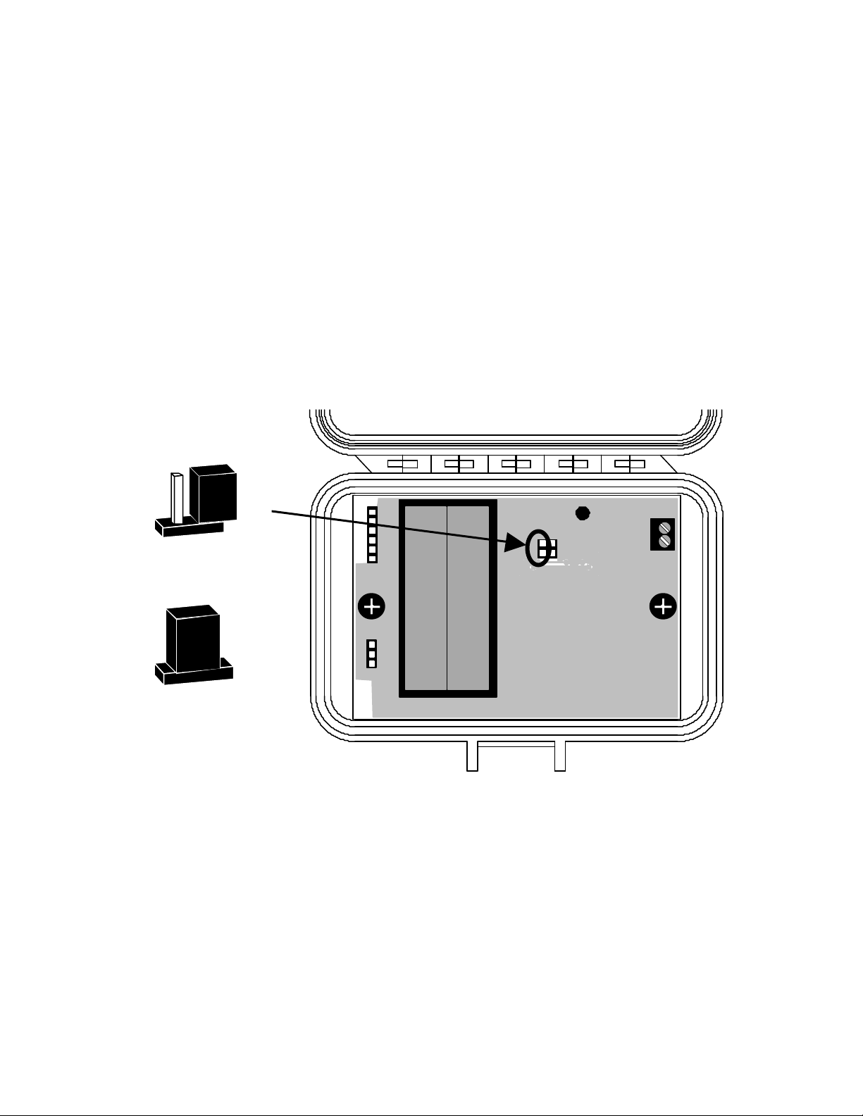
- Open the thumb-latch on the Temperature transmitter case, and place the
circuit board Jumper in the test position (see Diagram A). This will ensure that
the Receiver recognizes the Temperature transmitter when batteries are
eventually installed.
Jumper
Normal Position
Test Position
BOTTOM
Diagram A
2. Rain Transmitter
- The Rainfall transmitter operates on two AA Alkaline batteries (supplied).
o Do Not install the batteries yet.
- Remove the top of the Rain Collector by loosening the four Phillips head
screws and rotating the top counter-clockwise.
- Remove the blue cover to access the circuit board, and place the circuit board
Jumper in the test position (see Diagram B). This will ensure that the Receiver
recognizes the Rainfall transmitter when batteries are eventually installed.
Page 3
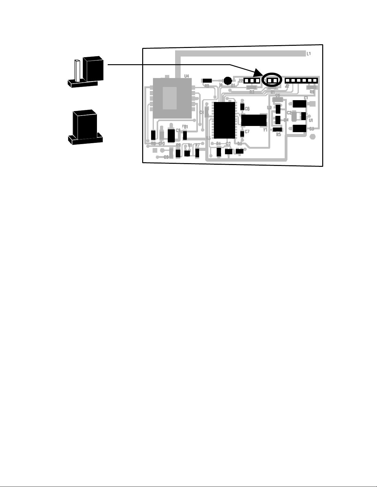
Jumper
Normal Position
Test Position
Diagram B
3. Wind Transmitter
- Insert two AA NiCad batteries (supplied) into the enclosed battery charger (be
sure to observe Polarity) and charge batteries for 12 hours.
o Note: Do not attempt to charge batteries other than NiCad batteries, as
they could explode, causing physical damage and/or fire.
- Feed the terminal lug end of the Yellow and Brown wires through one of the
rubber boots and connect the lugs to the terminals on the bottom of the wind
speed sensor using the brass nuts provided. The polarity does not matter.
o Note: Do Not adjust the nuts that are already on the sensor.
- Feed the terminal lug ends of the remaining 5 wires through the other rubber
boot and connect to the terminals on the bottom of the wind direction sensor
using the brass nuts provided.
o Connect the 5 wires to the wind direction sensor as follows:
§ White wire to Terminal 1
§ Orange wire to Terminal 2
§ Black wire to Terminal 3
§ Red wire to Terminal 4
§ Green wir e to Terminal 5
o Note: Do Not adjust the nuts that are already on the sensor.
- Slide the straight stub mast through the rubber boot and insert it into the
bottom of the wind speed sensor. Secure the sensor to the mast with the
supplied cotter pin.
- Slide the formed (“Z” shaped) stub mast through the other rubber boot and
insert it into the bottom of the wind direction sensor with the #3 terminal aligned
over the mast arm. Secure the sensor to the mast with the supplied cotter pin.
o Note: If the sensor is not installed with the #3 terminal aligned over the
mast arm, wind direction readings will be incorrect.
ES00057B
COMPONENT
SIDE
Page 4
3. Wind Transmitter (cont.)
- Remove the bottom portion of the black bracket on the back of the Wind
transmitter case, by loosening the four black screws.
- Place the Wind transmitter case on the horizontal section of the formed wind
direction mast with the antenna situated above the mast arm.
- Place the bottom portion of the black bracket behind the mast arm and secure
it in place with the four black screws that were removed.
- Secure both sensor stub masts to your antenna mast (not supplied) with the
two hose clamps provided.
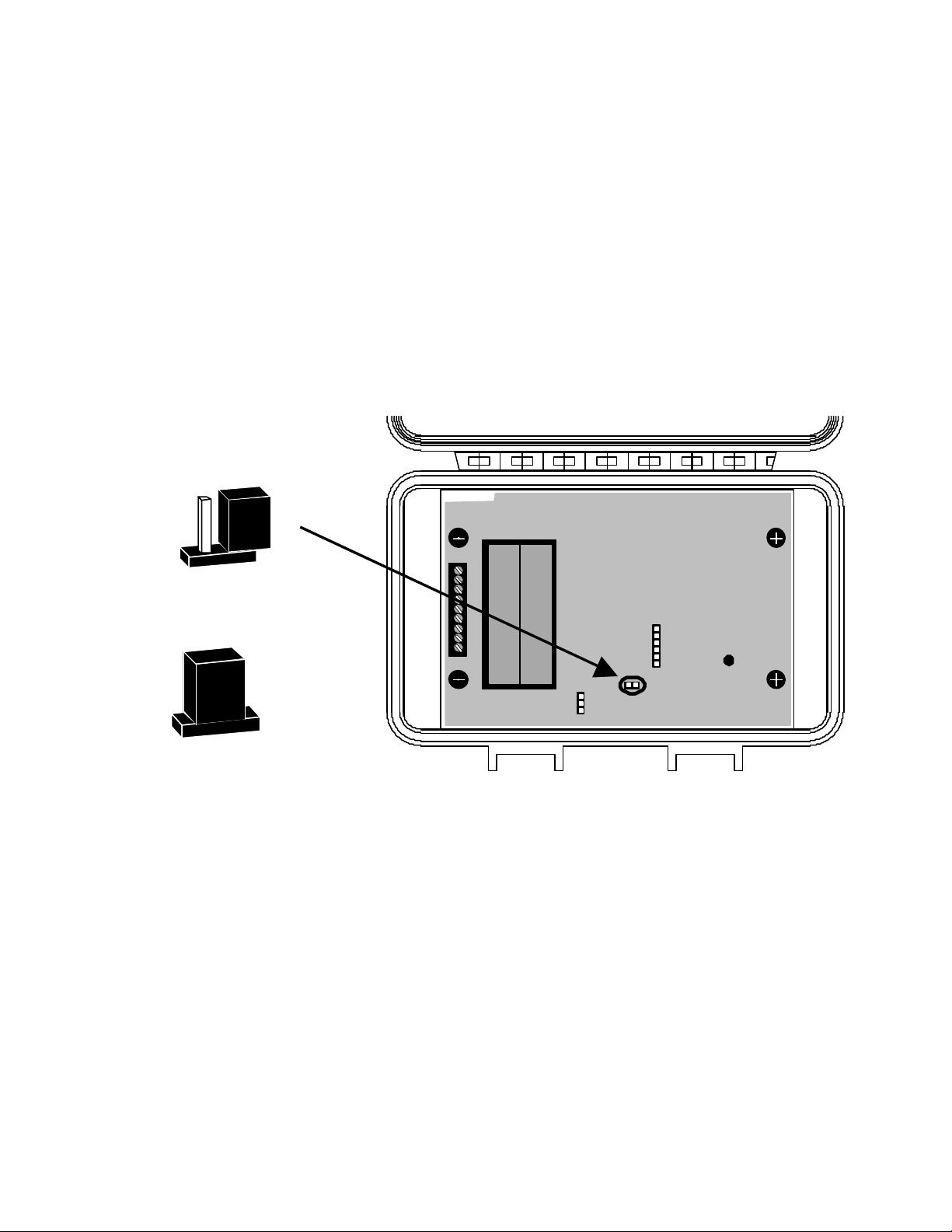
- Open the Wind transmitter case by lifting the two thumb latches, and place the
circuit board Jumper in the test position (see Diagram C). This will ensure that
the Receiver recognizes the Wind transmitter when batteries are eventually
inserted.
Jumper
SOLDER SIDE
Normal Position
Test Position
Diagram C
IV. Transceiver Testing & Sensor Installation (please follow directions in the order shown)
A. Instrument Display
- Move the instrument display and the individual sensors nearby the desired
installation location (the display may lie on a table or floor for testing purposes).
o This step is necessary to determine whether or not proper signals can
be obtained for each component, prior to final installation.
- Connect the AC adaptor(s) provided, to the instrument(s).
o If you have more than 1 instrument, wire 1 AC adaptor to each
instrument.
- Plug in all the AC adaptors.
Page 5

A. Instrument Display (cont.)
- The following should display on each instrument upon power-up:
o Merlin: all LEDs will illuminate, then “0” will display in the window and
the North LED will light.
o Mystic: all LEDs will illuminate, then a barometer reading will display in
the window.
o Rainwatch: “00.00” will display in the window.
o Cronus: all LEDs will illuminate, then current time will display in the
window.
B. Temperature Transmitter
- Install two AA alkaline batteries into the Temperature transmitter.
o The red LED on the Receiver box should blink every 4 seconds.
- Toggle the switch on the bottom of the Mystic instrument until current
temperature is displayed.
o The instrument will display the temperature from the sensor location.
- Move the Temperature tra nsmitter to desired installation location. (A North
exposure, 6’ off the ground, out of direct sunlight, is recommended).
- The red LED on the Receiver box should continue to light every 4 seconds.
o The sensor may take up to 2 hours to acclimate to outside temperature.
- If the signal is lost (LED does not blink), try moving the Temperature
transmitter.
- Once a suitable location has been established, remove the batteries and place
the test jumper back in the normal position (leave batteries disconnected for
now).
C. Rain Transmitter
- Install two AA alkaline batteries into the Rain Collector transmitter.
o The red LED on the Receiver box should blink every 4 seconds.
- Manually tip the dipper on the Rain Collector Base to one side.
- Rainwatch should display “00.01”.
- Move the Collector to desired installation location.
- The red LED on the Receiver box should continue to blink every 4 seconds.
- Manually tip the dipper on the Rain Collector Base and the Rainwatch should
display “00.02”.
- If the signal is lost (LED does not blink), try rotating or moving the Rain Collector.
- Once a suitable location has been established, remove the batteries and place
the test jumper back in the normal position (leave batteries disconnected for
now).
Page 6

D. Wind Transmitter
- Once fully charged, remove the NiCad batteries from the battery charger, and
install them into the Wind transmitter.
- Bring the mast to the desired installation location (rooftop).
o The red LED on the Receiver box should blink every 2 seconds.
- The red LED on the Receiver box should continue to blink every 2 seconds.
- Mount the mast to your mounting bracket (not supplied).
- Choose a location with at least 8’ of vertical clearance above objects on the
roof.
- The LED on the receiver should continue to blink every 2 secon ds. If the signal
is lost (LED does not blink), try an alternate mounting location or alternate
receiver location.
- Move the test jumper back to the normal position.
- Remove one battery, wait a few seconds and, then re-install the battery. This
will restart the unit in normal mode.
- Align the wind direction Z -mast arm so it is pointing to the EAST and the Solar
Panel is facing SOUTH and angled 22.5° above the horizon. Then secure the
mast per the instructions supplied with your mounting bracket.
V. Display Installation
- When deciding upon a location your weather instrument display, be aware of
possible interference from cordless phones, computer monitors, and other
household appliances.
- To lessen the chance of interference, mount the wireless Receiver at least 12’
away from such appliances.
- For best reception, avoid installation near large metallic surfaces.
VI. Receiver Installation
- Re-install the batteries in the rain and temperature transmitters.
- Cut a hole in the wall large enough for the Receiver to pass through.
- Place the Receiver inside the wall, either above or below the instruments.
- Anchor the instruments or wood panel to the wall using wood screws.
- Check all functions to ensure that instruments are displaying data.
- If you are having difficulty receiving transmissions, it may be necessary to
move either the Receiver or the Transmitter for an individual sensor.
- It is possible to connect the receiver up to 50’ away from the display. This may
help you locate the best signal reception.
Page 7
VII. Battery Information
- The AA alkaline batteries in the Temperature and Rain Collector transmitters
should last from 1 – 2 years depending on changes in condition. We
recommend replacing the batteries annually to avoid loss of data.
- The AA NiCad batteries in the Wind transmitter will continually recharge via the
internal solar charging system. The characteristics of NiCad batteries are such
that they could need replacement every 2 -3 years. The life expectancy varies
depending on many factors, including temperature and amount of sunshine at
your location.
VIII. Error displays
When no data is received at the “In” terminal of a Merlin or Mystic the display will show a series
of dashes.
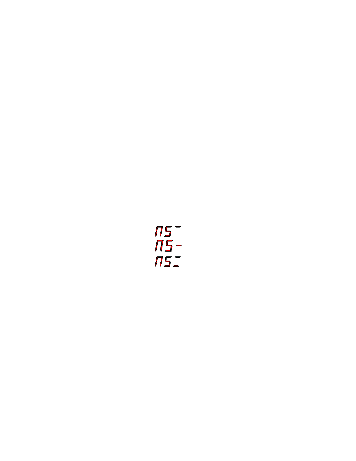
If a transmitter is no longer responding to the receiver, Merlin and/or Mystic will display “NS” (No
Signal) followed by one or more bars indicating which transmitter is not responding. The top bar
is wind, the middle bar is temperature and the bottom bar is rain.
Examples:
Wind not responding
Temperature not responding
Wind and rain not responding
IX. User Notes
Page 8

X. Information for the Wireless Instrument user
Warning: Changes or modifications to this unit not expressly approved by the party responsible
for compliance could void the user’s authority to operate the equipment.
NOTE: This equipment has been tested and found to comply with the limits for a Class B digital
device, pursuant to Part 15 of the FCC Rules. These limits are designed to provide reasonable
protection against harmful interference in a residential installation. This equipment generates,
uses and can radiate radio frequency energy and, if not installed and used in accordance with
the instructions, may cause harmful interference to radio communications. However, there is no
guarantee that interference will not occur in a particular installation. If this equipment does
cause harmful interference to radio or television reception, which can be determined by turning
the equipment off and on, the user is encouraged to try to correct the interference by one or
more of the following measures:
• Reorient or relocate the receiving antenna.
• Increase the separation between the equipment and receiver.
• Connect the equipment into an outlet on a circuit different from that to which the receiver
is connected.
• Consult the dealer or an experienced radio/TV technician for help.
Samuel Barnett Boulevard
New Bedford, MA 02745
(508) 995 -2200
 Loading...