

Page 1
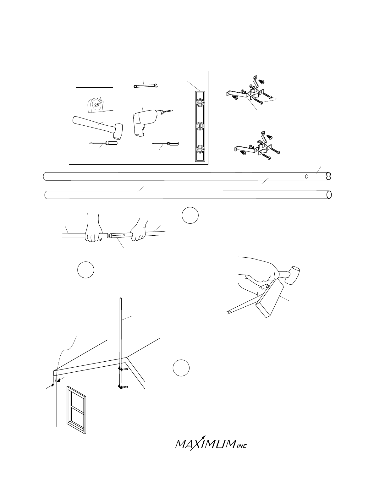
4” WALL MOUNT
INSTALLATION
PROPER INSTALLATION IS IMPORTANT. IF YOU NEED ASSISTANCE, CONSULT A CONTRACTOR,
ELECTRICIAN OR TELEVISION ANTENNA INSTALLER (CHECK WITH YOUR LOCAL BUILDING SUPPLY,
OR HARDWARE STORE FOR REFERRALS).
MAST B
TOOLS
REQUIRED
TAPE MEASURE
HAMMER
SLOTTED SCREW
DRIVER
SWAGED END
3/8” WRENCH
3/8”
DRILL WITH
1/8” DRILL BIT
PHILLIPS SCREW
DRIVER
MAST B
MAST A
LEVEL
CLAMPING
SCREWS
4 INCH WALL
BRACKET
SWAGED
END
MAST A
1
Slip the swaged end of mast A into the
round end of mast B.
2
Tap the two sections together with a hammer.
A piece of wood will protect the end from
damage.
BRACKET WILL
ACCOMMODATE
UP TO 4 INCH
OVERHANG OF EAVE
MAST
ROOF
PEAK
WOOD BLOCK
3
Select a location that will provide the highest,
unobstructed position for the wind sensors.
30 Samuel Barnet Blvd.
New Bedford, MA 02745
(508) 995-2200
Page 1
Page 2
18”
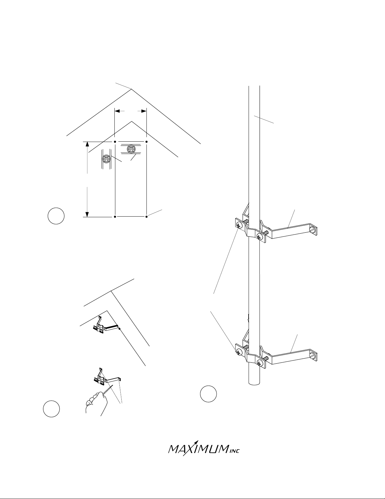
MINIMUM
4” WALL MOUNT
INSTALLATION
ROOF
PEAK
8 1/4”
MAST
LEVEL
1/8” PILOT
HOLES
4
Drill two 1/8” level pilot holes 8 1/4” apart for each
bracket. Brackets must be separated from each
other by at least 18” for mast stability. Both
brackets must be aligned vertically for the mast
to be straight when installed.
ROOF
PEAK
CLAMPING
SCREWS
4 INCH
BRACKET
4 INCH
BRACKET
5
LAG SCREWS
Secure the brackets
with the lag screws
6
30 Samuel Barnet Blvd.
New Bedford, MA 02745
(508) 995-2200
Page 2
Slip mast into brackets and tighten
with the carriage bolts.
 Loading...