

Page 1
SIROCCO
INSTALLATION
PROPER INSTALLATION IS IMPORTANT. IF YOU NEED ASSISTANCE, CONSULT A CONTRACTOR
ELECTRICIAN OR TELEVISION ANTENNA INSTALLER (CHECK WITH YOUR LOCAL BUILDING SUPPLY,
OR HARDWARE STORE FOR REFERRALS). TO PROMOTE CONFIDENCE, PERFORM A TRIAL
WIRING BEFORE INSTALLATION.
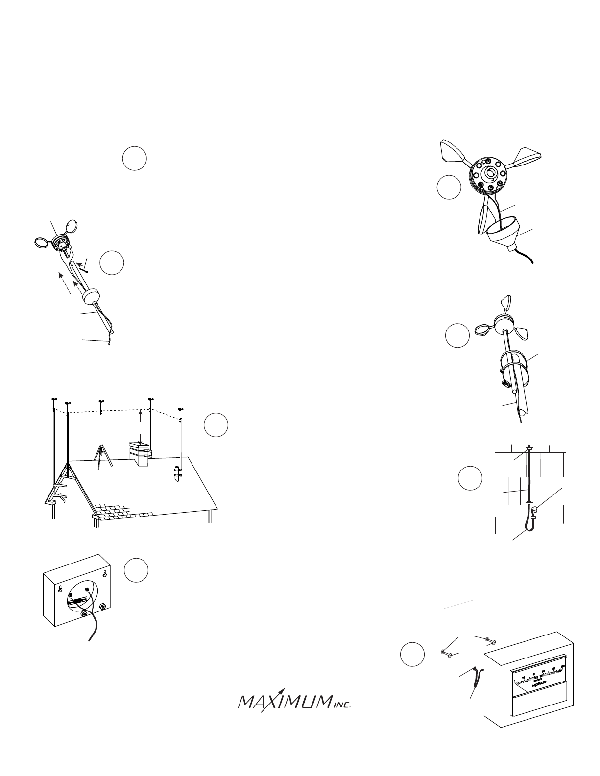
Determine where you are going to locate both the
1
rooftop sensor and the read-out.
WIND SPEED
SENSOR
STRAIGHT
STUB MAST
2-CONDUCTOR
CABLE
WALL
MOUNT
COTTER
PIN
EVE
MOUNT
Feed the terminal lug end of the 2-conductor cable through
the rubber boot and connect the lugs to the terminals on the bottom
of the wind speed sensor. (Do NOT adjust the nuts that are already
on the sensor). The polarity does not matter.
Slide the stub mast through the rubber boot and insert the stub mast
3
into the bottom of the wind speed sensor. Secure with the cotter pin.
Coat all conections with silicone sealant and slip the boot over the sensor.
Secure the sensor and the stub mast to your antenna
mast (not supplied) with the two hose clamps. Radio
Shack and similar stores have a selection of antenna
masts and roof mounting brackets. Choose a mount that best
suits your location and provides at least eight feet of vertical
clearance above objects on the roof.
TRIPOD
MOUNT
8 FEET
CHIMNEY
MOUNT
5
VENT-PIPE
MOUNT
Follow the instructions supplied with the antenna
mount and secure the mast to the mount.
Secure the wire to the building using
cable clips (do not use regular staples).
Form a drip loop where wire enters hole
drilled through the exterior wall.
Caulk the hole when done.
Feed the cable through the wall to where the read-out is
7
going to be located. Attach the wires to the rear of the
read-out as shown. (Do NOT adjust the nuts that are
already on the meter). The polarity does not matter.
2
4
TALL MAST
6
WALL
WALL
ANCHOR
(NOT SUPPLIED)
2-CONDUCTOR
CABLE
BOOT
HOSE CLAMPS
CABLE
CLIPS
CAULK
WIRE
DRIP
LOOP
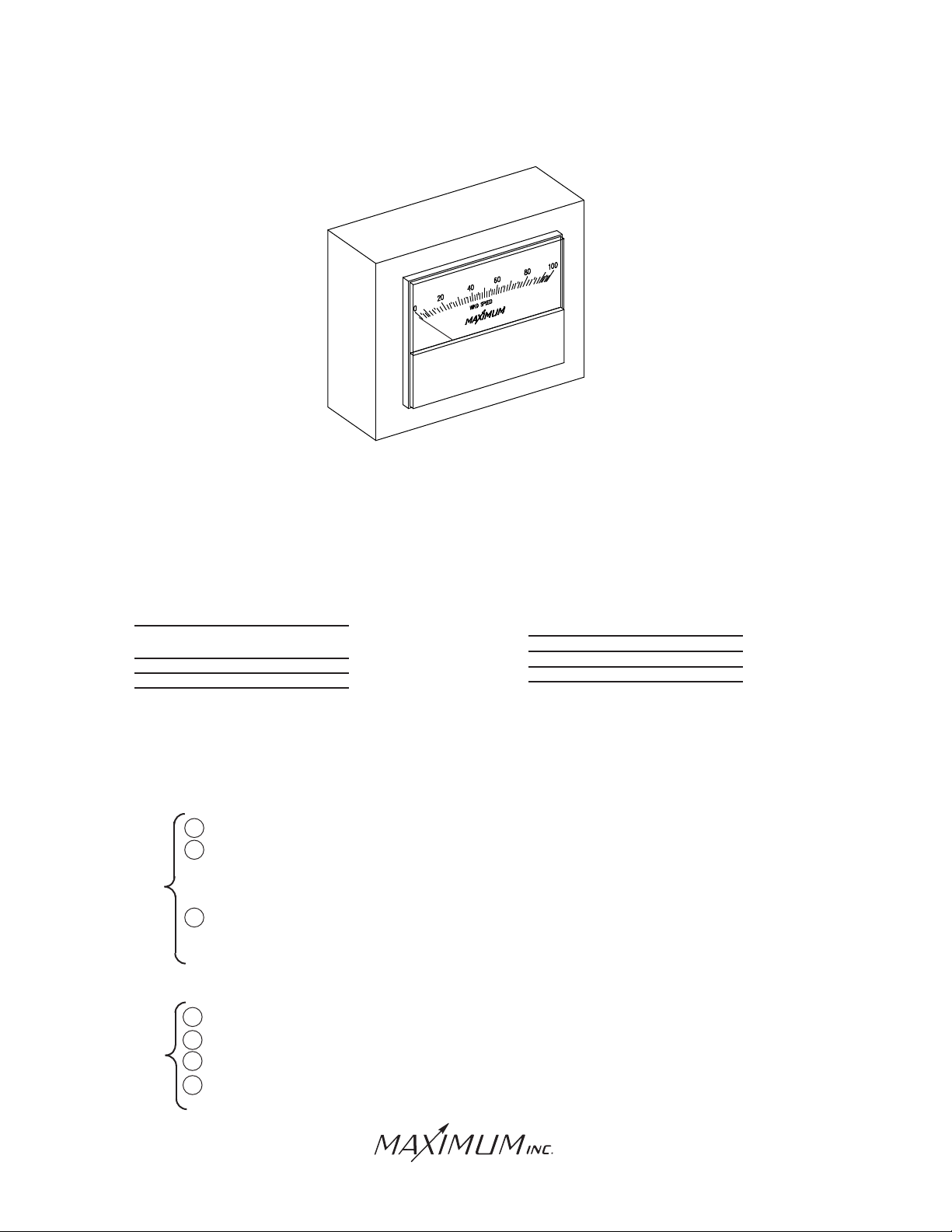
The Sirocco read-out is free standing. It can also be mounted
8
on a wall using the key hole cut outs in the back of the instrument's
wood block.
Samuel Barnett Boulevard
New Bedford, MA 02745
(508) 995-2200
SCREW
WIRE-HOLE
WIRE
Page 2
SIROCCO
OPERATION
The Sirocco is a self-powered wind speed measuring instrument. It does not need
batteries or an external power supply. In normal operation it requires no maintenance.
ADDITIONAL INFORMATION
Cables can be shortened or lengthened without affecting accuracy
WIRE
GAUGE
24
22
(supplied with instrument)
20
19
18
MAXIMUM FEET
WITHOUT RECALIBRATION
300'
500'
750'
1000'
1250'
WIRE
GAUGE
16
14
12
10
MAXIMUM FEET
WITHOUT RECALIBRATION
2000'
3200'
5000'
8000'
TROUBLE SHOOTING
Maximum Instruments are accurate and reliable. Most problems that occure are due
to loose or corroded connections. If, after checking the connections, there is still a
problem, determine if the problem is with the sensor or the brass read-out.
1. Disconnect the wires from the back of the read-out.
2. Attach a low range AC Analog Voltmeter to the wires. If the sensor is operating
If there is
properly, you will achieve these approximate reading: 8-9 MPH = 0.15 VAC rms,
wind
17 MPH = 0.31 VAC rms, 51 MPH = .97 VAC rms, 102 MPH 2.0 VAC rms
3. If the sensor delivers these approximate readings, then the read-out
is faulty. If the sensor does not produce these readings, then either the
sensor or the wire is faulty.
1. Disconnect the wires from the back of the read-out.
2. Connect an ohm meter to the wires.
If there is
3. The ohm meter should indicate between 500 and 1,000 ohms.
no wind
4. If there is a good reading on the ohm meter, then the read-out
is faulty. If the reading is bad, then the sensor or wire is faulty.
Samuel Barnett Boulevard
New Bedford, MA 02745
(508) 995-2200
Page 3
IMPORTANT ADDITIONAL INFORMATION
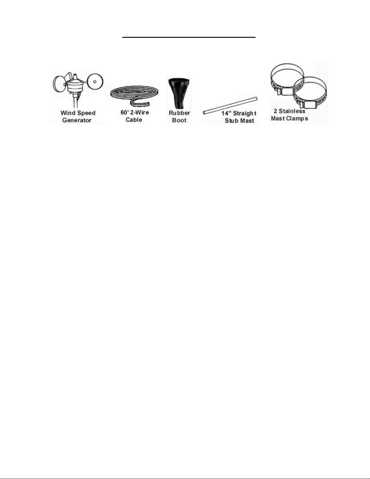
Components: Along with the indicator, the following components are included with this instrument:
Rooftop sensor: To insure a clear unobstructed path for the wind to the sensor, it should be
mounted on some type of antenna mast at least 8-10’ above the highest object on your roof.
Remember, your roof is also an obstruction and it usually requires at least 8’ of height to avoid the
turbulence it creates.
Sensor: Properly installed, your sensor will require virtually no maintenance at all. Our sensors
do not utilize brushes or wiping contacts. All bearings are Rulon-J self lubricating type and will
perform for many years in the harshest environments.
Specifications: All instrumentation or measuring devices have accuracy tolerances and
specifications. Making comparisons between different pieces of equipment is appropriate provided
the specified accuracies of both are known.
Measurement Range Guaranteed Accuracy
Wind Speed 0-100 MPH ±3% Full Scale & Mid Scale
Page 4

Electrical Damage – Common Causes & Recommended Prevention
Electrical damage can be caused by many different factors. Below are some of the more common causes and
some suggested methods of minimizing potential problems.
Common Causes:
Storm Activity – lightening in your area can do damage to your instruments in different ways. The obvious
way is due to a direct or nearby strike. In addition, lightening storms, dust storms, dry snowstorms and
strong dry winds can all cause static electricity to build up on and around your external sensors. Regardless
of the cause this built up electricity can discharge itself through the cable connecting the external sensors to
the instrument.
Power Surges – A surge may come from the electric company’s switching generators or power grids, from
local industries or after power interruption when accumulated power suddenly surges back through AC lines.
Even the on-and-off switching of large electrical appliances, such as refrigerators or clothes dryers can
create damaging fluctuations. This is especially true with sensitive weather recording devices.
Yourself – Are you constantly giving and/or receiving a shock every time you touch a doorknob or another
person? If so you have a great deal of static electricity in your environment. Depending on where you live,
static electricity may be a year round problem or only a seasonal problem. In either case, it is possible for a
person to carry enough of a charge to damage an instrument.
Recommended Prevention:
Ground Your Mounting Mast – IMPORTANT: PVC and fiberglass are not recommended
mast materials as
they can store high amounts of static electricity within themselves. It is recommended that you follow the
grounding instructions that came with your mounting mast, while also maintaining accordance to your local
Electric Code. In the absence of instructions for your mast system, the following generic guidelines from the
N
ational Electric Code may be helpful.
1) The NEC requires that the antenna mast and mount be grounded directly. No splices or connections are
allowed in the ground wire between the mast and the ground rod.
2) Attach one end of a No. 8 (or thicker) copper or aluminum ground wire to the antenna mast. Note: As static
electricity issues are more common for weather sensors than direct lightening strikes, consider installing the
ground wire as physically close to the wind sensors as possible to best combat static ele ctricity issues. For
multi-piece (or telescoping) masts, consider connecting the ground to each separate section of the mast.
3) For painted or coated masts, scrape off the coating around the area where the contact will be made. This
will ensure a good, solid connection. (Once the ground is attached to the mast, any scraped off portion that
is exposed should be recoated with paint or other sealant.)
4) Next, run the ground wire to ground as directly as possible. Standard wire staples can be used to secure the
ground wire against the side of the house. Avoid making 90° or sharper turns with the ground wire. A
lightning charge has difficulty making such a turn and therefore may discharge into the house. Make ground
wire bends as smooth and as gradual as possible.
5) The ground wire must be connected to a ground rod. Water pipes or plumbing fixtures are not acceptable.
A good copper-coated steel ground rod driven at least 3 feet into the ground is required. Special clamps that
provide a solid connection between the ground wire and ground rod should be used
Use Surge Protectors – For the AC adapter, a UL 1449 rated surge protector with EMI/RFI filtering is
recommended. This rating will be clearly listed on the packaging of any good quality surge protector.
Discharge Yourself – If the instruments are located in an environment where static electricity is a proble m ,
make sure that you discharge yourself before touching the instrument(s). The shock that you get from
touching a doorknob or another person can often be sufficient to damage an instrumen
t.
30 SAMUEL BARNET BOULEVARD NEW BEDFORD, MASSACHUSETTS 02745 U.S.A.
TEL. 508.995.2200 WWW.MAXIMUM-INC.COM FAX 800.989.2580
 Loading...