

Page 1
MERLIN
INSTALLATION
PROPER INSTALLATION IS IMPORTANT. IF YOU NEED ASSISTANCE, CONSULT A CONTRACTOR, ELECTRICIAN
OR TELEVISION ANTENNA INSTALLER (CHECK WITH YOUR LOCAL BUILDING SUPPLY, OR HARDWARE STORE
FOR REFERRALS). TO PROMOTE CONFIDENCE, PERFORM A TRIAL WIRING BEFORE INSTALLATION.
GREEN
WIRE
BOOT
WIND DIRECTION
SENSOR
TERMINAL
#4
TERMINAL #4
MUST ALIGN
WITH Z-MAST
ARM
1
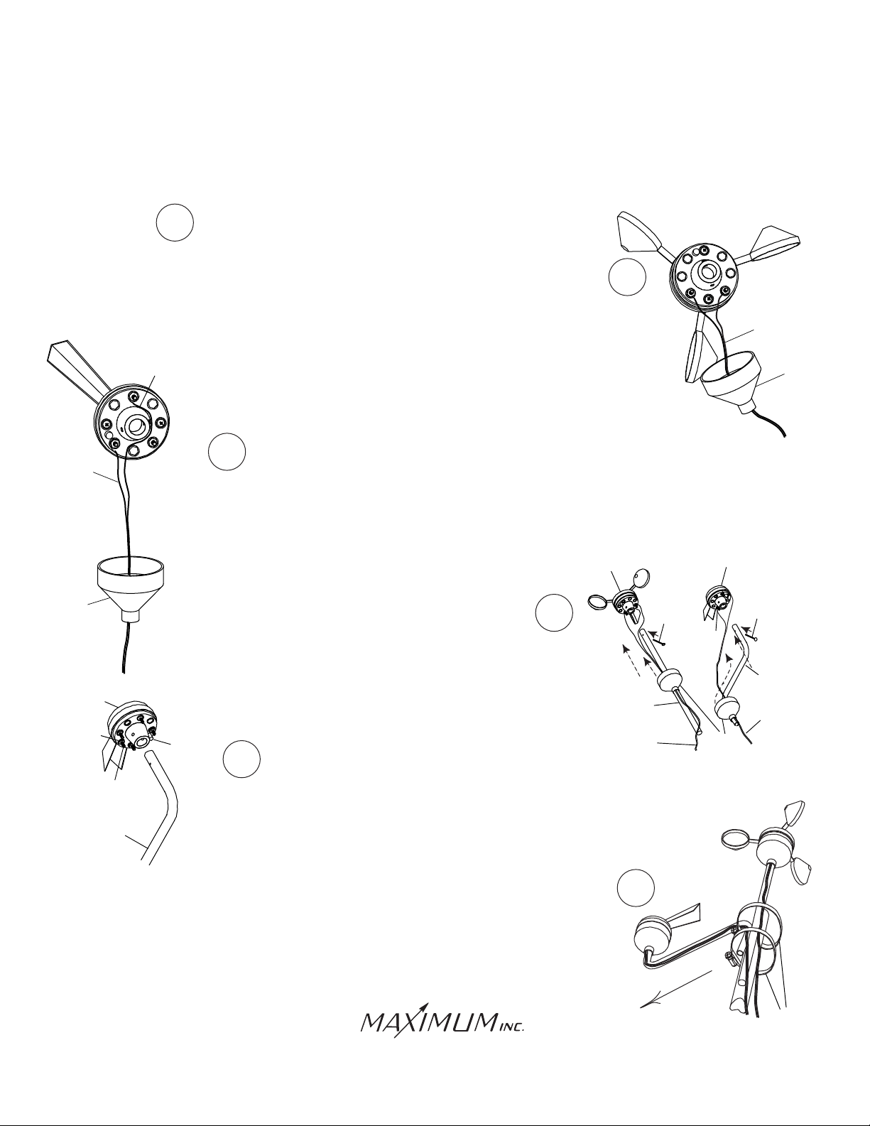
Feed the teminal lug end of the black and white wires through
one of the rubber boots and connect the lugs to the terminals on the
bottom of the wind speed sensor using the brass nuts provided. The polarity
does not matter. (Do NOT adjust the nuts that are already on the sensor).
RED
WIRE
4
5
BOSS
Determine where you are going to locate both the
rooftop sensors and the read-out.
Feed the terminal lug end of the red and green wires through the other
3
rubber boot. Connect the red wire to the terminal marked #4.
Connect the green wire to the terminal marked #5. The polarity MUST be
observed. Use the hex nuts provided. (Do NOT adjust the nuts that are
already on the wind direction sensor).
WIND SPEED
SENSOR
Slide the stub masts through the rubber boots and
insert the stub masts into the bottom of the sensors. Secure
with the cotter pins. Coat all wire connections with silicone
sealant and slip the boots over the sensors.
4A
When connecting the wind direction sensor
to the Z-mast, make certain that terminal #4
is aligned with the Z-mast arm. If the sensor
is not installed in this manner your wind
direction readings will be incorrect.
4
STRAIGHT
STUB MAST
2
BLACK & WHITE
WIRES
COTTER
PIN
BLACK AND WHITE
WIRES
BOOT
WIND DIRECTION
SENSOR
COTTER
PIN
4
Z-STUB
MAST
RED & GREEN
WIRES
BOOT
Secure the sensors and stub masts to your antenna mast (not supplied) with
the two hose clamps. Align the wind-direction Z-mast arm to true North.
Radio Shack and similar stores have a selection of tall masts and roof
mounting brackets. Choose a mount that best suits your location and
provides at least eight feet of vertical clearance above objects on the roof.
Samuel Barnett Boulevard
New Bedford, MA 02745
(508) 995-2200
5
NORTH
HOSE
CLAMPS
Page 2
MERLIN
BRASS
FROM AC
ADAPTER
INSTALLATION
(continued)
6
VENT-PIPE
MOUNT
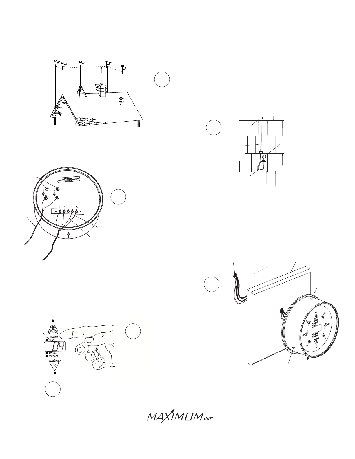
Follow the instructions supplied with the antenna
mount and secure the mast to the mount.
WALL
MOUNT
TRIPOD
MOUNT
EVE
MOUNT
CHIMNEY
MOUNT
8 FEET
Secure the wire to the building using cable clips (do not use regular
staples). Form a drip loop where the wires enter the hole drilled
through the exterior wall. Caulk the hole when done.
NUTS
Feed the cables through the wall to where the read-out is going to
8
be located. Attach the wires to the rear of the read-out as shown.
The red wire from the direction sensor cable connects to terminal #4.
the green wire to terminal #5. Connect the black and white wires
GREEN
WIRE
RED
WIRE
from the speed sensor to terminals #1 and #2. The polarity does
not matter. Although the cable shield itself is not connected, shielded
cable must be used. Connect the wires from the AC adapter to the
meter. The polarity does not matter. (Do NOT adjust the nuts that
are already on the meter).
7
CABLE-HOLE
CABLE
CLIPS
CAULK
WIRE
DRIP
LOOP
PANEL
Mount the brass read-out directly over the cable feed-thru-hole
9
to avoid crimping the wire under the lip. We recommend mounting
the read-out on one of our pre-drilled and centered panels. Plug the
power supply into a 110 VAC power outlet.
10
When Merlin first starts up it will
perform a brief self-test and then
go to the "Present" function mode.
Reset all memory functions (see operating instructions).
11
Resetting gives Merlin a fresh starting point for your
reference.
Samuel Barnett Boulevard
New Bedford, MA 02745
(508) 995-2200
WALL
SCREW
SCREW
Page 3
MERLIN
OPERATION
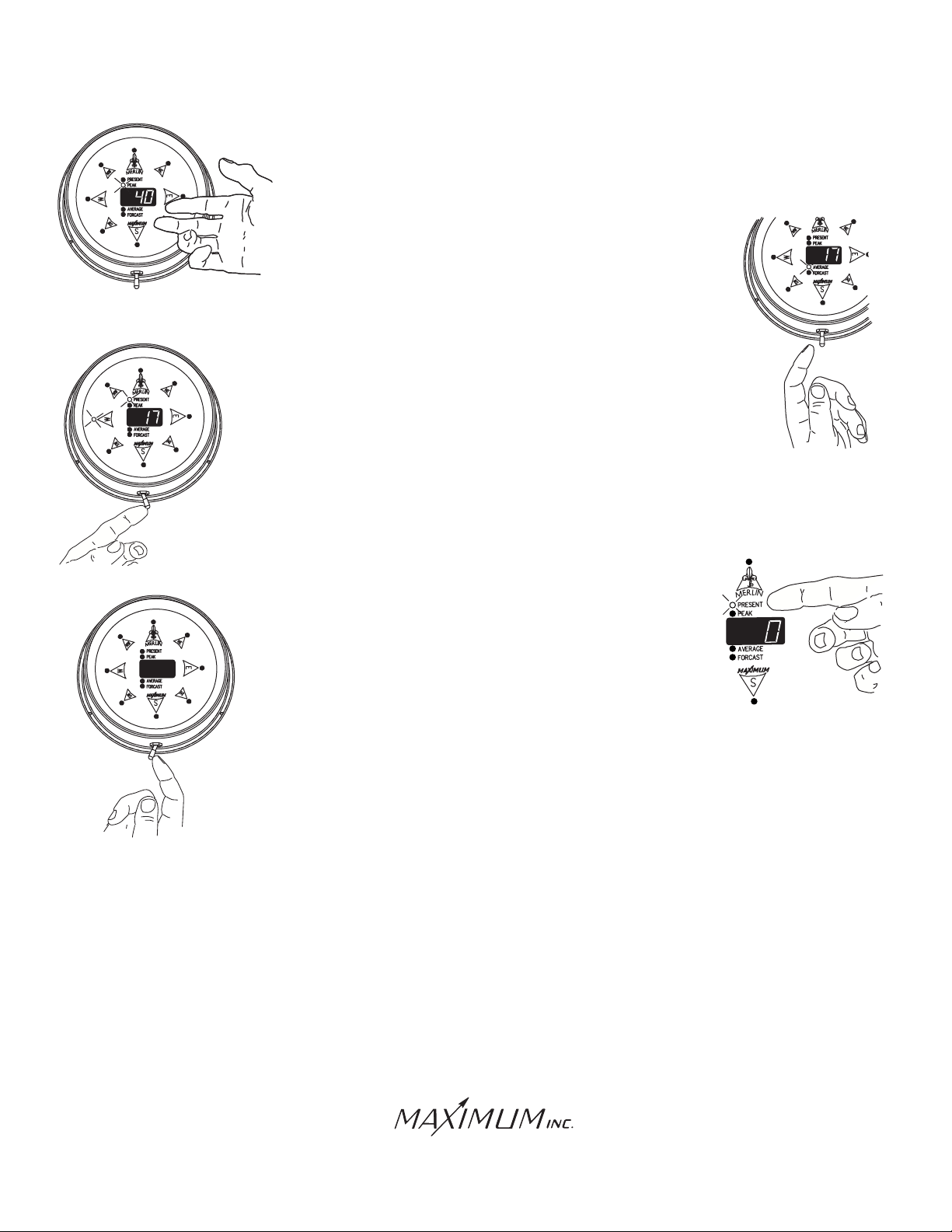
With the switch in the center (resting) position, MERLIN will
display the information indicated by the illuminated function
(Present, Peak, Average, or Forcast).
To select a function, move the switch to the right and
allow it to return to the center. This toggles Merlin to
the next function. Repeat this until you see the
function that you wish.
To auto-sequence through all of the functions, hold
the switch to the right for at least three seconds.
You will see each fucntion light stay on and the
corresponding information displayed for
approximately four seconds. MERLIN will
then move to the next fuction automatically.
To return to the manual sequencing mode, move the switch
briefly to the right and then let it return to center.
To reset all the stored funcions at once, select the "Present"
function by moving the switch to the right and releasing until
the "Present" light is illuminated. Then hold the switch to the
left until the display blanks out (about six seconds). The unit
will then perform a self-test and return to normal operation.
Resetting the Peak, Average and Forcast functions Individually
can be done by toggling to the function that you wish to reset. Then
hold the switch to the left for at least 6 seconds. At that point you will
see the display reset itself.
IMPORTANT FACTS ABOUT YOUR MERLIN
Peak Wind- When first powering up MERLIN, after long power outages, or when totally resetting, the Peak
Wind direction LEDs will not function until at least 1 MPH wind has been recorded.
Average Wind- The first reading after setting the Average will be the current wind speed. This reading will
settle out as MERLIN accumulates more data. Prevailing wind direction lights will not function until 12
minutes after powering up or resetting. As with the wind speed there will be no prevailing direction
indication if there is not wind.
Samuel Barnett Boulevard
New Bedford, MA 02745
(508) 995-2200
Page 4
MERLIN
IMPORTANT FACTS ABOUT YOUR MERLIN (CONT.)
Forcast- When first powering up MERLIN, after long power outages, or when totally resetting, the
Forcast display will read "hld" (hold) for 24 minutes while MERLIN is loading its memory. During the
25th minute MERLIN will make a trend reading "inc" (increase), "dec" (decrease), "---" (no change)
in wind speed based on comparing two 12-minute blocks of time. If there has been no wind for an
entire 12 minute timing interval, the direction lights will blank out. If there is no wind for the next
12 minutes then the display will show "---" and the direction lights will remain off.
Wind Direction- MERLIN takes a reading every second. When the wind changes direction very
rapidly (faster than 1 second), some direction lights may not light. This is normal operation as
MERLIN is simply between readings.
Latch Up- Power Line disturbances or improper powering up (plugging in the
AC Adapter before wiring) can cause a blank or improper display reading. If
MERLIN is "latched up" proceed as follows:
1. Remove the Brass Indicator from the wall or panel.
2. Set the switch on the back of the indicator to the
UNLATCH position.
3. Wait 15 seconds.
4. Set switch to NORMAL
5. Remount Indicator on wall or panel.
NORMAL
UNLATCH
During long power outages MERLIN's display will blank out and the instrument will not continue to
accumulate data. It will preserve the previously accumulated data for up to 15 hours.
Using the Forcast function and periodically updated Average function together, you can often watch
not only small changes in wind conditions but more significant "backing" and "veering" pattens fortelling
frontal movements.
If you are unsure as to when Forcast made it's last update, wait more than 12 minutes and read again
(it updates every 12 minutes).
When MERLIN is in the Peak, Average, and Forcast modes the direction lights blink. This indicates
that you are observing recorded data and not the present wind direction.
Setting the switch to Auto does not erase stored data.
You do not need to time the 6 second reset time, MERLIN will blank out the display to indicate that the
memory has been erased.
Samuel Barnett Boulevard
New Bedford, MA 02745
(508) 995-2200
Page 5
MERLIN
TROUBLE SHOOTING
(WIND DIRECTION)
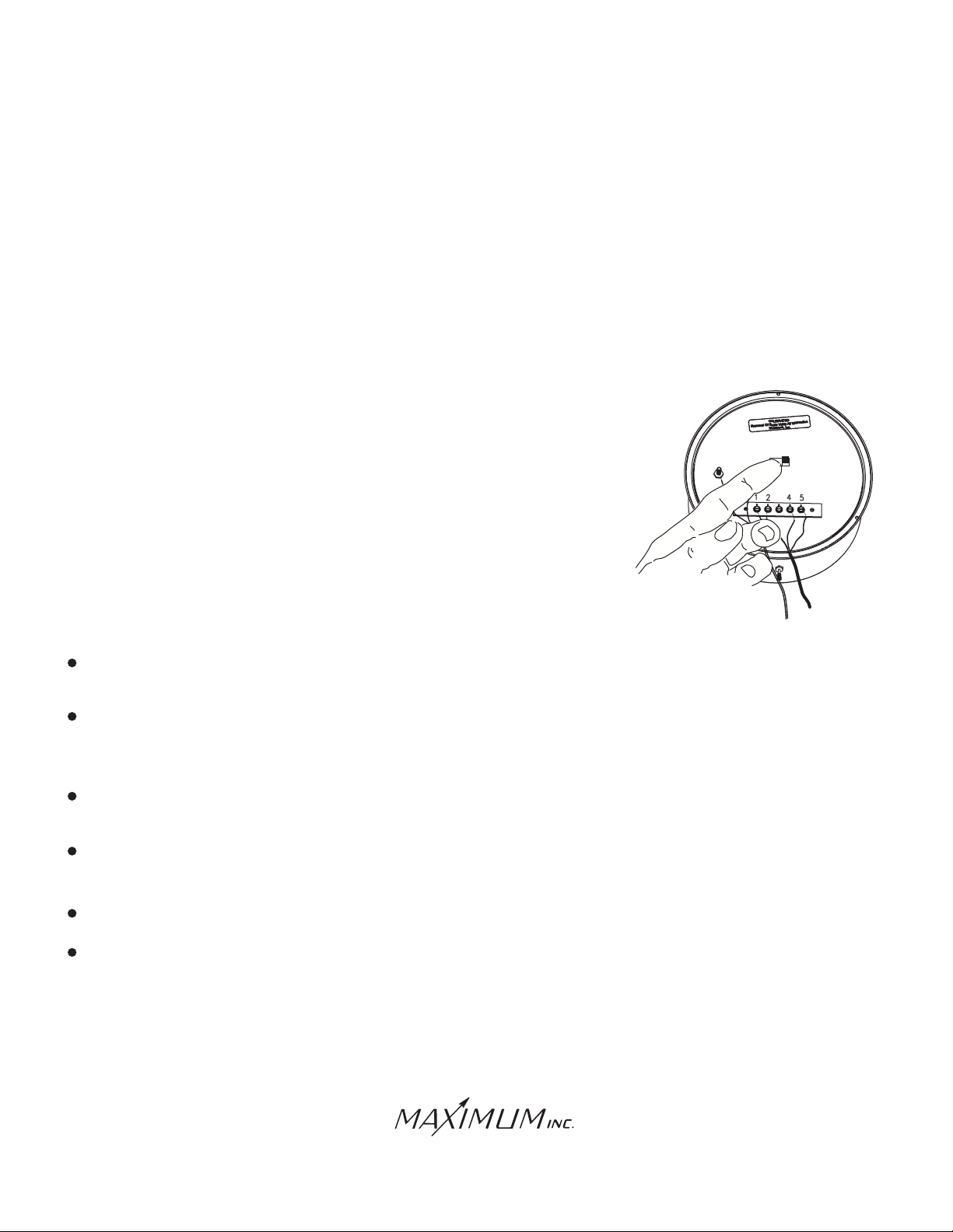
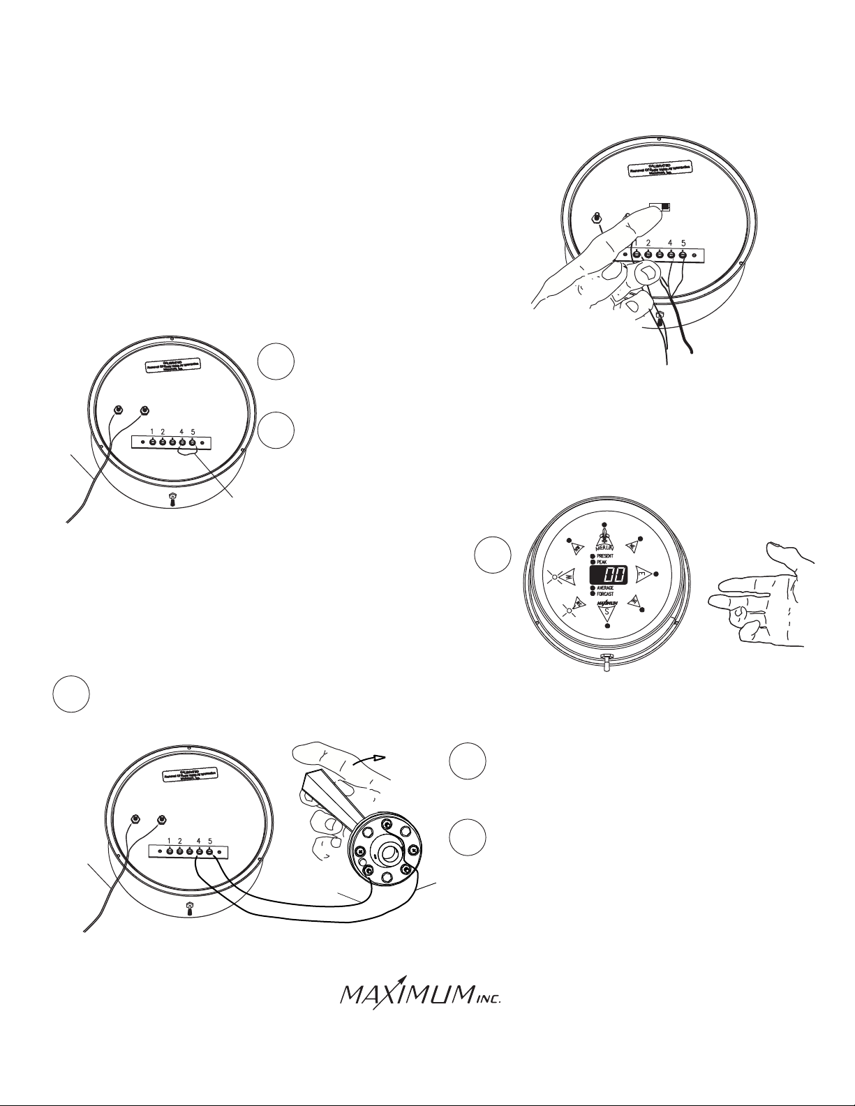
Perform the latch up corrections as previously detailed.
FROM AC
ADAPTER
The unit will now perform the self test, all LEDS will light
for about 3 seconds. If you did not have time to check
that all LEDS light, repeat the procedure. This will cause
the self test to start again. If some or all of the LEDS do
not light, then the fault is in the instrument.
IF ALL LEDS LIGHT......
1
Disconnect the sensor wires from the back of the meter.
2
Connect a jumper wire (a paper clip will suffice)
between terminals #4 and #5
JUMPER WIRE
(OR PAPER CLIP)
3
The instrument should indicate
"0" speed and "WSW" direction. If not,
the fault is in the instrument.
NORMAL
UNLATCH
IF THE INSTRUMENT TESTS OKAY......
Reconnect the wind direction wires. If there is still a fault in the wind direction portion, then
1
the problem is in the wind direction sensor or the installed wire.
2
4
FROM AC
ADAPTER
GREEN
WIRE
5
Samuel Barnett Boulevard
New Bedford, MA 02745
(508) 995-2200
3
RED
WIRE
Remove the sensor from the roof and
connect it to the indicator with short
pieces of wire.
Rotate the vane slowly and observe the
lights. If it still does not operate properly,
then the fault is in the sensor. Otherwise
the fault is in the installed wire.
Page 6
MERLIN
TROUBLE SHOOTING
(WIND SPEED)
VOLT-OHMETER
FROM AC
ADAPTER
BLACK AND
WHITE WIRES
FROM ROOF TOP
SENSORS
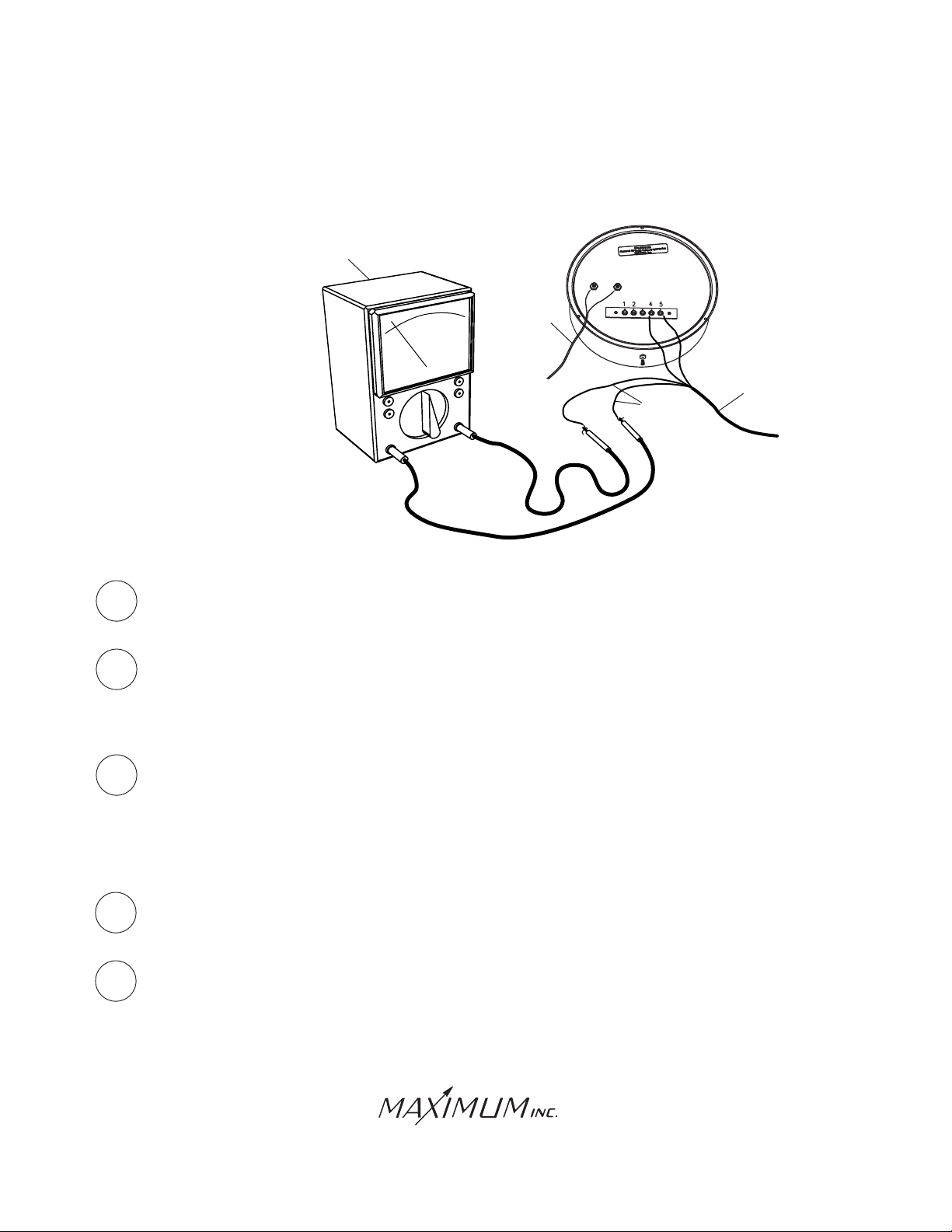
IF THERE IS WIND......
1
2
3
Disconnect the black and white wires from the back of the of the indicator and connect
them to volt-ohmeter as shown. Set for low range AC Volts.
If the sensor is operating properly, you will achieve these approxiamte readings:
8-9 MPH = 0.15 VAC rms
17 MPH = 0.31 VAC rms
51 MPH = 0.97 VAC rms
102 MPH = 2.00 VAC rms
If the sensor delivers the above approximate voltages, plus or minus, depending on an
estimate of the wind speed, the fault lies in the indicator. If it does not deliver these
voltages, the fault lies in the sensor or installed wire.
IF THERE IS NO WIND......
1
2
Disconnect the black and white wires from the back of the of the indicator and connect
them to volt-ohmeter as shown. Set the range for Ohms.
If the sensor and wire are good, the ohm meter should indicate between 500 and
1,000 ohms. If there is a good reading on the ohm meter, then the idicator is at fault.
If the reading is wrong, then the sensor or installed wire is at fault.
Samuel Barnett Boulevard
New Bedford, MA 02745
(508) 995-2200
Page 7
IMPORTANT ADDITIONAL INFORMATION
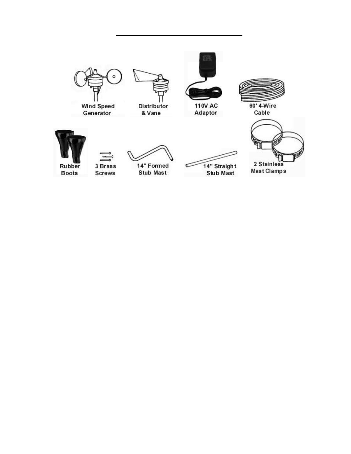
Components: Along with the indicator, the following components are included with this instrument:
Rooftop sensors: To insure a clear unobstructed path for the wind to the sensors, they should be
mounted on some type of antenna mast at least 8-10’ above the highest object on your roof.
Remember, your roof is also an obstruction and it usually requires at least 8’ of height to avoid the
turbulence it creates.
AC Adaptor: This instrument requires its own AC Adaptor. Due to the various power
requirements of each Maximum instrument, attempting to run more than one instrument on a single
adaptor could cause improper operation and/or damage to the instrument(s) thereby voiding your
5-year warranty.
Sensors: Properly installed, your sensors will require virtually no maintenance at all. Our sensors
do not utilize brushes or wiping contacts. All bearings are Rulon-J self lubricating type and will
perform for many years in the harshest environments.
Brass Case: Your brass case is solid brass A70-30 Holloware quality, with a durable lacquer
finish. It is in fact a piece of jewelry and should be treated as such. It should be cleaned at least
once a week to keep airborne pollutants (dust, etc…) and any moisture from collecting on the case
thereby attacking the lacquer. At no time should you use an abrasive cleaner or cloth on the brass
case. Simply use a soft cloth or soft paper towel with a mild glass cleaner to wipe the case clean.
If your instruments are in a summer home, and you are not able to clean them regularly, simply lay
a small cloth or towel across the top two -thirds so that dust cannot settle on the finish.
Specifications: All instrumentation or measuring devices have accuracy tolerances and
specifications. Making comparisons between different pieces of equipment is appropriate provided
the specified accuracies of both are known.
Measurement Range Guaranteed Accuracy
Wind Speed 0-255 MPH ±2% Full Scale & Mid Scale
Wind Direction (Indicator) 16 Compass Points Zero Error (Digital Display System)
Wind Direction (Sensor) ±11.25 Degrees
 Loading...