

Page 1
Page 2
TABLE OF CONTENTS
3
Quick start guide
Specifications
Safety guidelines
Know your table saw
Assembly
Operation
Maintenance
Troubleshooting
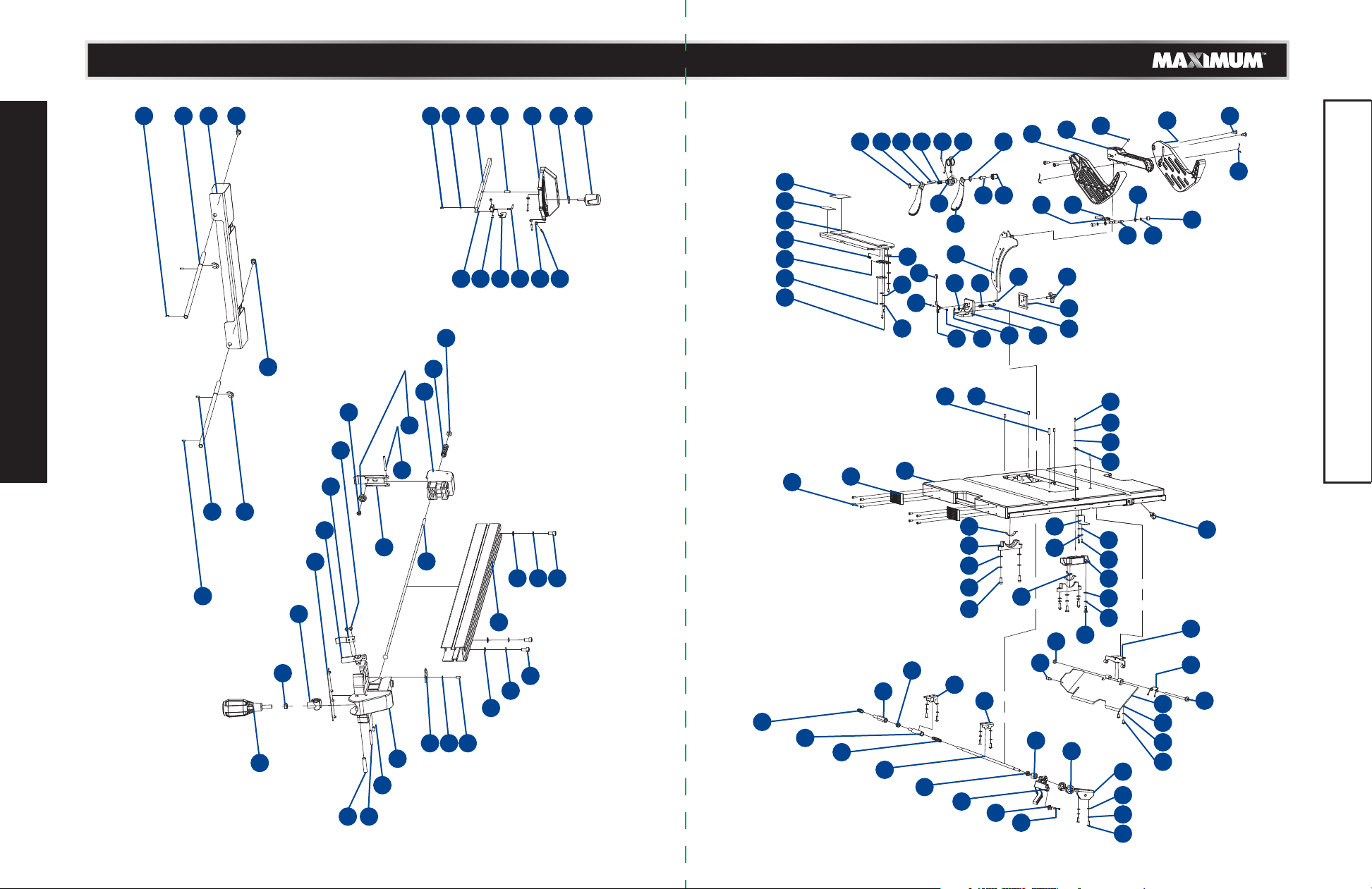
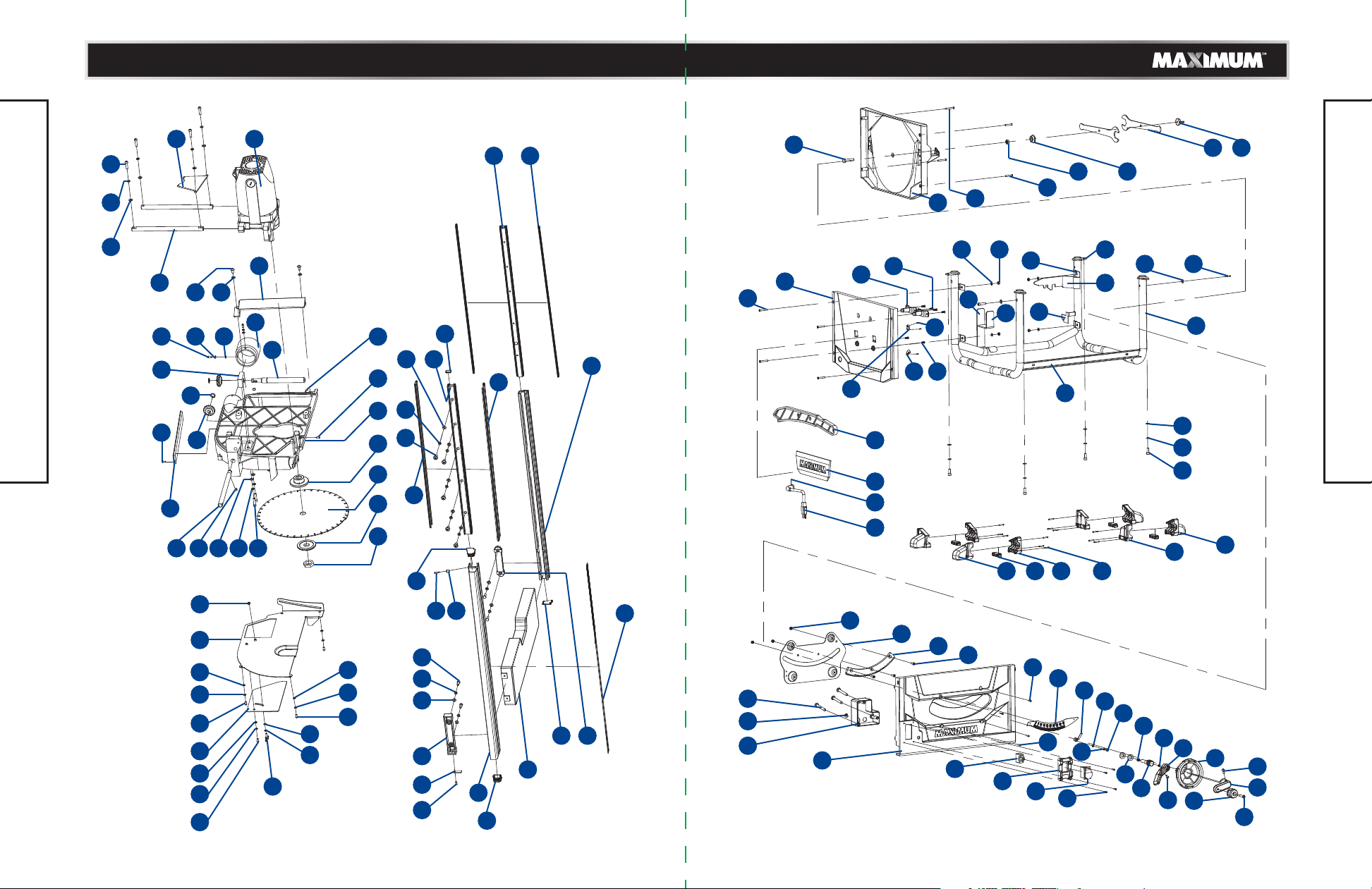
Exploded view
Parts list
Warranty
4
5
6
13
19
37
46
48
50
54
58
TABLE OF CONTENTS
NOTE: If any parts are missing or damaged, or if you have any
questions, please call our toll-free helpline at 1-888-670-6682.
SAVE THESE INSTRUCTIONS
This manual contains important safety and
operating instructions. Read all instructions and
follow them when using this product.
Page 3
4
model no. 055-6766-2 | contact us 1-888-670-6682
model no. 055-6766-2 | contact us 1-888-670-6682
5
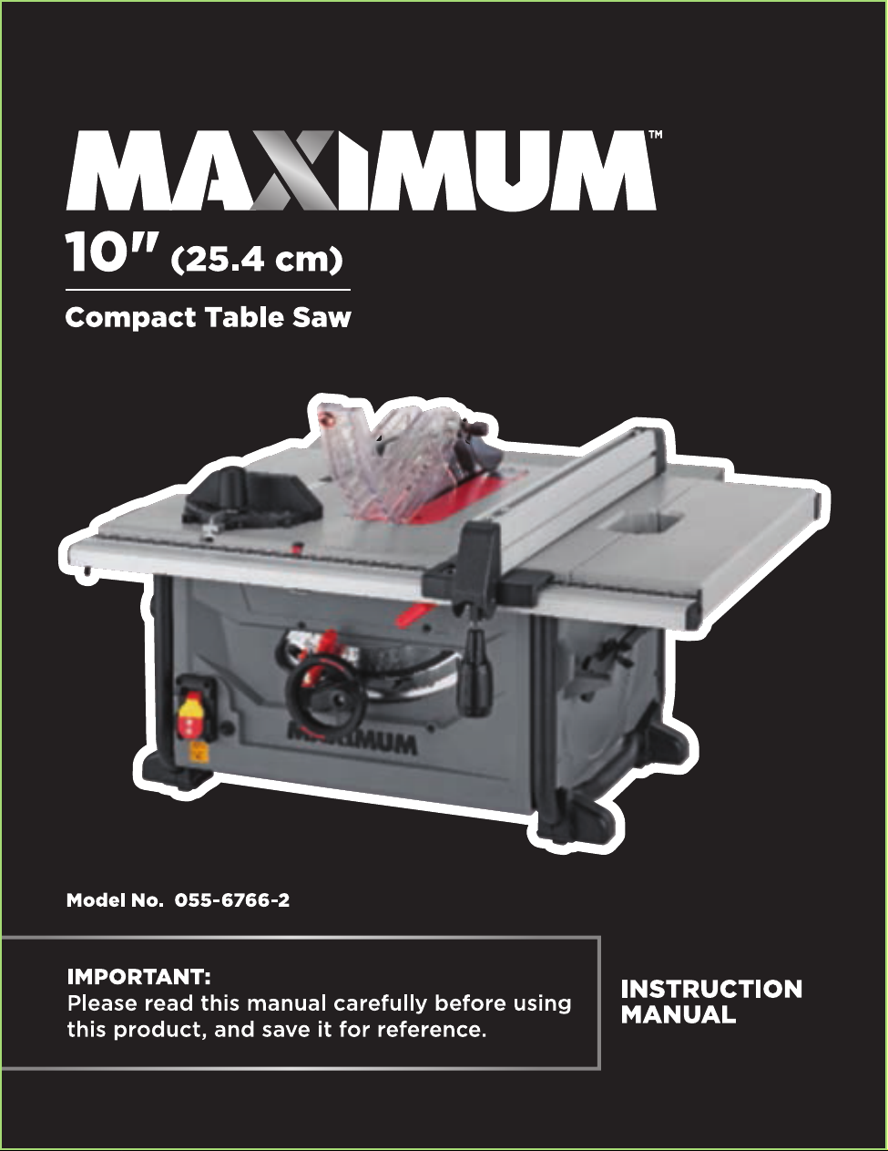
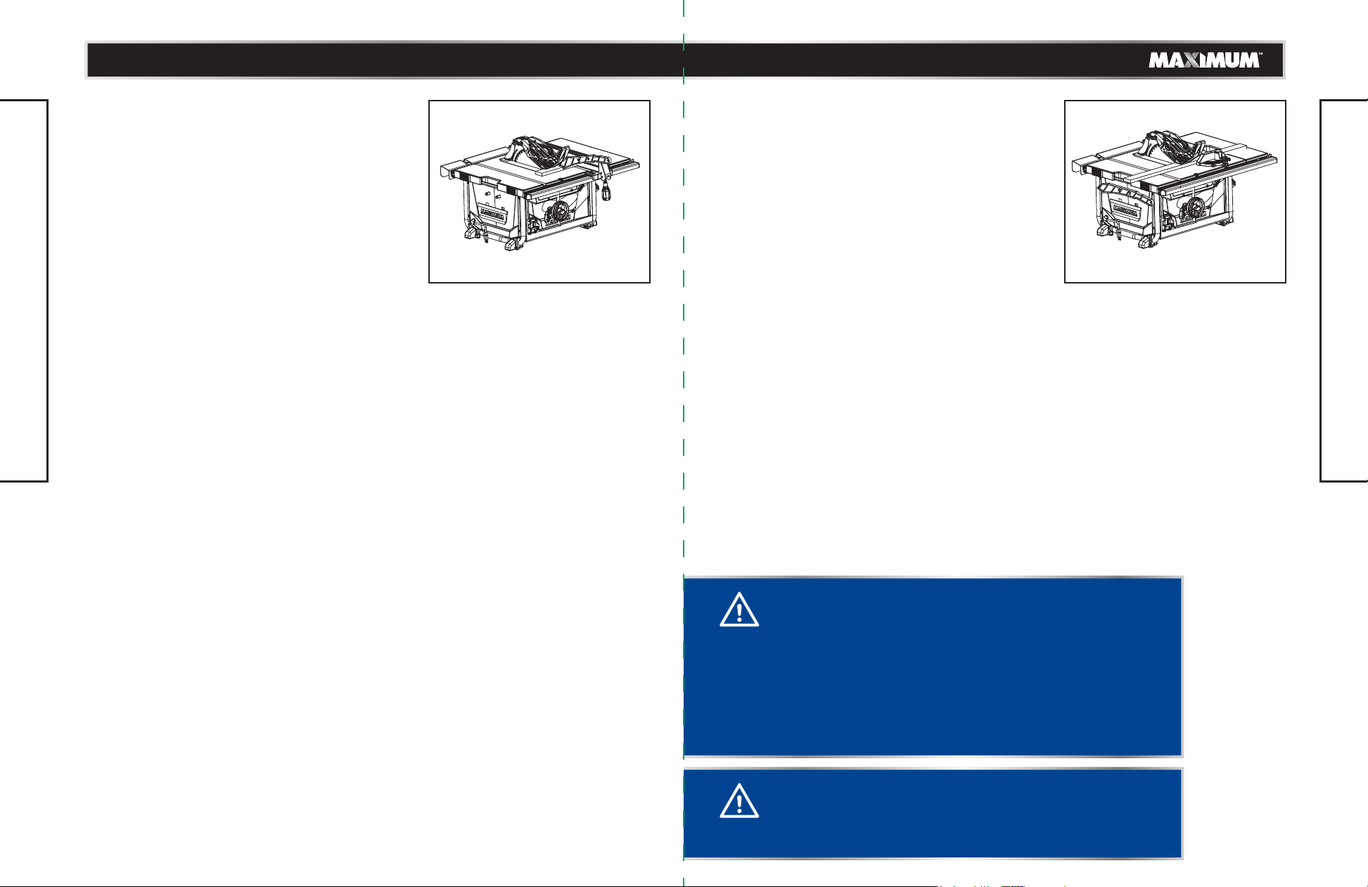
This portable table saw is designed to cut wood and wood composition products only.
The tool can be used for straight-line cutting operations such as crosscutting, ripping,
mitring 0-45° mitre angle, bevel crosscutting 0-45° blade bevel and 90° mitre angle,
0-45° blade bevel and 0-45° mitre angle, cabinet making and woodworking.
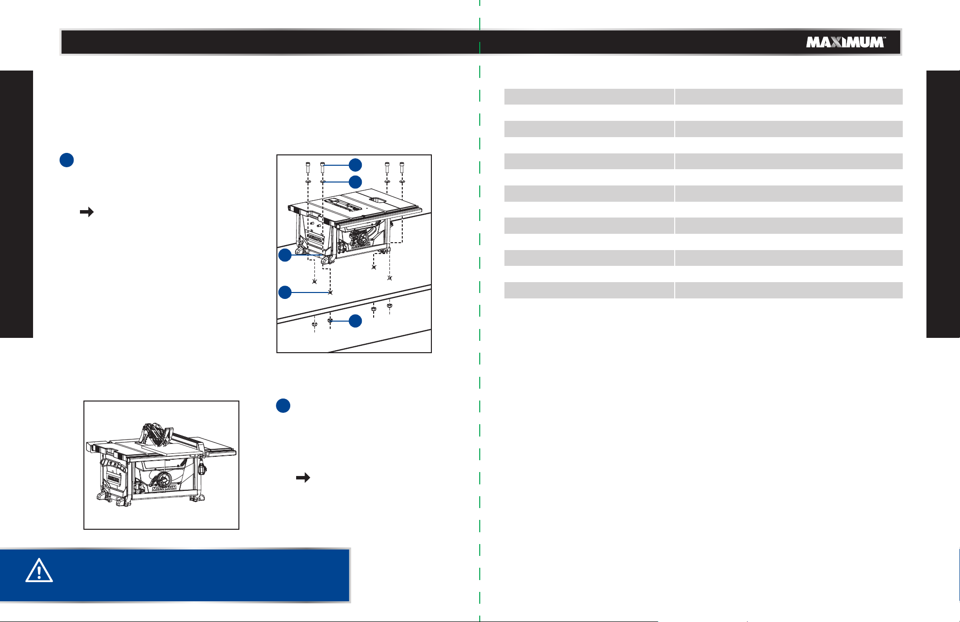
• Drill four 3/8" (10 mm) diameter
1
holes (2) through workbench.
• Place table saw on workbench
aligning holes in tube frame with
holes drilled in workbench.
see page 22.
QUICK START GUIDE
SPECIFICATIONS
Motor
Motor speed
Blade
Sliding extension table size
3
4
1
2
Outfeed support size
Main table size
Depth of cut at 90°
Depth of cut at 45°
Rip capacity
Bevel range
Mitre range
Table height
Weight
120 V, 60 Hz, 15 A
3100 RPM (no load)
10" (25.4 cm) 40-tooth carbide-tipped
5 63/64 x 21 1/16" (15.2 x 53.5 cm)
24 x 2 1/2" (61 x 6.5 cm)
24 x 21 1/16" (61 x 53.5 cm)
3 1/8" (7.9 cm)
2 5/32" (5.5 cm)
8" (20.3 cm) left, 24 1/2" (62.2 cm) right
0-45°
0-60° (left and right)
14 3/16" (36 cm)
61 lb (27.6 kg)
SPECIFICATIONS
5
• Adjust the blade so that it is
2
approximately 1/8" (3.2 mm)
higher than the workpiece.
• Hold the workpiece flat on the
table and against the fence. Keep
the workpiece approximately 1"
(2.5 cm) away from the blade.
see page 41.
CAUTION!
• Read and understand the following instructions to get the
best use of this portable table saw.
Page 4

6
model no. 055-6766-2 | contact us 1-888-670-6682
model no. 055-6766-2 | contact us 1-888-670-6682
7
SAFETY GUIDELINES
This manual contains information that relates to PROTECTING PERSONAL SAFETY and
PREVENTING EQUIPMENT PROBLEMS. It is very important to read this manual carefully
and understand it thoroughly before using the product. The symbols listed below are
used to indicate this information.
DANGER!
Potential hazard that will result in serious injury or loss of life.
WARNING!
Potential hazard that could result in serious injury or loss of life.
CAUTION!
Potential hazard that may result in moderate injury or damage to equipment.
Note: The word “Note” is used to inform the reader of something the operator needs to
know about the tool.
SAFETY RECOMMENDATIONS
These precautions are intended for the personal safety of the operator and others
SAFETY GUIDELINES
working with the operator. Failure to follow these instructions may result in a permanent
loss of vision, serious personal or even fatal injury, property damage and/or tool damage.
Please take time to read and understand these instructions.
Safety is a combination of common sense, staying alert and knowing how your table saw
works.
GENERAL SAFETY RULES
• Store all safety guidelines and instructions for future use.
• This device is not intended for use by people (including children) lacking experience
with electrical power tools unless they have received some instruction about how the
device is to be used. Children have to be supervised to ensure that they do not play
with the device.
WARNING!
• Read all the safety guidelines and instructions before you
use this electric power tool!
WARNING!
• When using electric power tools, the following essential
safety measures have to be observed to prevent electric
shocks, injury and fire hazards. Failure to adhere to the
safety guidelines and instructions can cause electric shock,
fire and/or severe injuries.
• Store the operating instructions so that they are always available to the user of the tool
when it is being operated.
• Remove the protective padding around the motor before using.
• Pay close attention to instructions on reducing the risk of kickback.
• Always use push sticks when ripping narrow workpieces and when making non-through
cuts.
• If you lend this device to other people, always hand over these operating instructions
to ensure safe use. Instruct inexperienced people in accordance with these safety
instructions.
• Keep your work area tidy. Untidiness in your work area can cause accidents.
• Pay attention to the surrounding conditions. Do not expose the electric power tool to
rain. Do not use electric power tools in damp or wet conditions. Ensure that the work
area is well lit. Do not use electric power tools where there is a danger of fire or
explosion.
• Protect yourself against electric shocks. Avoid bodily contact with earthed parts (e.g.
pipes, radiators, electric hobs or cooling appliances).
• Keep other people away from the work area. Do not let other people, especially
children, touch the electric power tool or the power cable. Keep them away from your
work area.
• Store unused electric power tools safely. Unused electric power tools should be stored
in a dry, high-lying or locked place, out of the reach of children.
• Do not overload your electric power tool. It works better and more securely within the
stated output range.
• Use the correct electric power tool. Do not use inefficient machines for heavy work. Do
not use the electric power tool for purposes for which it was not intended. For example,
do not use circular saws to cut wooden masts or logs.
• Wear suitable clothing. Do not wear baggy clothing or jewellery, as they can be caught
by moving parts. When working outdoors, anti-slip shoes are recommended. If you have
long hair, wear a hair net.
• Wear safety equipment. Wear safety goggles. If the work creates dust, wear a dust
mask.
• Attach the dust extraction unit. If there are connections for dust extraction and
collection equipment, then make sure that the equipment is correctly attached and
used.
• Never use the cable for purposes for which it is not intended. Do not use the cable to
pull the plug out of the power socket. Protect the cable from heat, oil and sharp edges.
• Secure the workpiece. When necessary, use clamping devices to secure the workpiece.
The workpiece is secured better that way than by hand.
• Avoid taking abnormal stances. Make sure you stand securely and keep your balance
at all times.
• Look after your tool with care. Keep the cutting tool sharp and clean so that you are
SAFETY GUIDELINES
Page 5
8
model no. 055-6766-2 | contact us 1-888-670-6682
model no. 055-6766-2 | contact us 1-888-670-6682
9
able to work better and more safely with it. Observe the guidelines on lubrication and
exchanging tools. Check the power cable of the electric power tool regularly. In case of
damage, let a qualified specialist repair it. Check extension cords regularly and replace
them if they are damaged. Keep the handles dry, clean and free of oil and grease.
• Pull the plug out of the power socket when the electric power tool is not in use, before
maintenance and when exchanging tools, such as saw blades, drills and mills.
• Do not leave keys in the device. Before you switch the device off, check that keys and
setting tools have been removed.
• Avoid starting the device accidentally. Make sure that when you insert the plug into the
power socket, the power switch is turned off.
• Use an extension cord when working outdoors. Only use extension cords outdoors that
are authorized for outdoor use and are correspondingly marked.
• Be attentive. Be careful. Carry out your work sensibly.
• Check the electric power tool for any sign of damage. Before continuing work with the
electric power tool, safety devices or easily damaged parts have to be carefully checked
to ensure that they function properly and are not defective. Check that moving parts
are working properly and are not jammed or damaged. All parts must be correctly
assembled by an experienced individual, unless stated otherwise in the operating
instructions, and meet all required conditions in order to guarantee that the electric
SAFETY GUIDELINES
power tool functions without a problem. Damaged switches have to be replaced by a
qualified electrician. Do not use electric power tools if the power switch cannot be turned
on and off.
• Let a qualified electrician repair your electric power tool. This electric power tool meets
applicable safety standards. Repairs are only allowed to be carried out by a qualified
electrician, using original replacement parts; otherwise accidents may occur.
SPECIFIC SAFETY RULES FOR TABLE SAW
• No other people may stand in the direct vicinity of the machine when it is in use. People
not operating the machine must maintain a suitable, safe distance.
• Never lay the power cable over the machine table.
• Use the push rod to pass the workpiece safely into the saw blade. Do not come too
close to the saw blade.
• Make sure that the thickness of the material to be cut is less than the maximum possible
cutting depth.
• Never cut “hands-free”. The workpiece must always lie level on the machine table and
be moved along the stop. The workpiece must always be pressed hard against the stop.
• Never cut workpieces that are so small that they cannot be safely pressed against the
stop and could turn.
• Never cut workpieces that are so small that they cannot be moved by the push rod at a
safe distance from the saw blade.
• Only cut one workpiece at a time. Never cut several workpieces simultaneously.
Workpieces must not be placed behind or on top of each other.
• There is a danger of the workpiece “jamming” and slipping away.
• Make sure that the workpiece cannot slip while being cut or get jammed in the saw
blade.
• Clean the work area and the workpiece after each cut.
• Never reach into the openings of the device. Never insert objects into the openings of
the device (e.g. the saw blade casing, dust extraction adaptor). There is a danger of
being cut. Never reach around or over saw blade.
• Never remove the cutting piece if the machine is still switched on or running. There is a
danger of cutting yourself.
• Cut workpieces may have sharp edges, ridges or wooden splinters. There is a danger of
cutting injuries.
• Always switch the machine off and remove the power plug when you leave the machine.
• Never expose the device to rain or extreme moisture.
• Do not perform any cuts with this table saw other than those described in these
operating instructions. Do not saw seams and notches.
• Table saws must not be used for slitting (notches that end in the workpiece).
• Failure to comply with these warnings may result in serious personal injury.
USE SAFETY GOGGLES AND EAR PROTECTION:
ALWAYS WEAR EYE PROTECTION THAT CONFORMS WITH CUL
REQUIREMENTS. FLYING DEBRIS can cause permanent eye damage.
The tool is loud and the sound can cause hearing damage. Always wear
ear protection to help prevent hearing damage and loss. Failure to comply
may result in moderate injury.
WARNING!
• The use of other insertion tools and accessories can
present a danger of injury.
WARNING!
• Switch the device off, remove the plug from the power
socket and let the machine come to a standstill. No
foreign bodies are allowed to be on the workpiece or the
machine table! Cut pieces of the workpiece can be caught
by the rotating cutting disc and be flung from the tool
and work area.
SAFETY GUIDELINES
Page 6
10
model no. 055-6766-2 | contact us 1-888-670-6682
model no. 055-6766-2 | contact us 1-888-670-6682
11
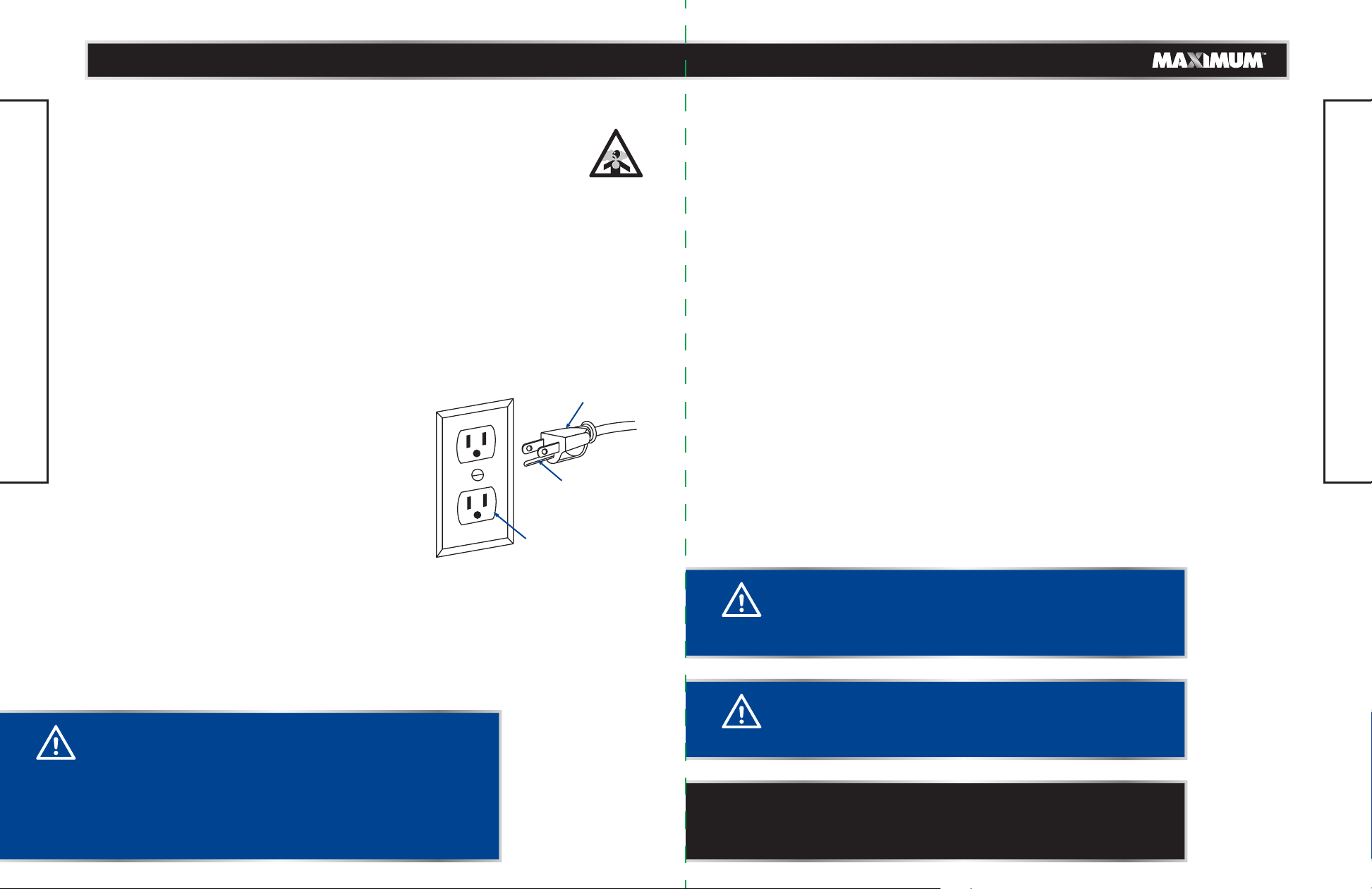
USE DUST MASK:
Some dust created by sawing contains chemicals that are known to cause
cancer, birth defects or other reproductive harm. Some examples of these
chemicals come from lead-based paints, crystalline silica from bricks, cement
and other masonry products, and arsenic and chromium from
chemically-treated lumber. To reduce exposure to these chemicals, work in a
well-ventilated area with approved safety equipment, such as dust masks that are
specially designed to filter out microscopic particles.
ELECTRICAL SAFETY
GUIDELINES FOR USING EXTENSION CORDS:
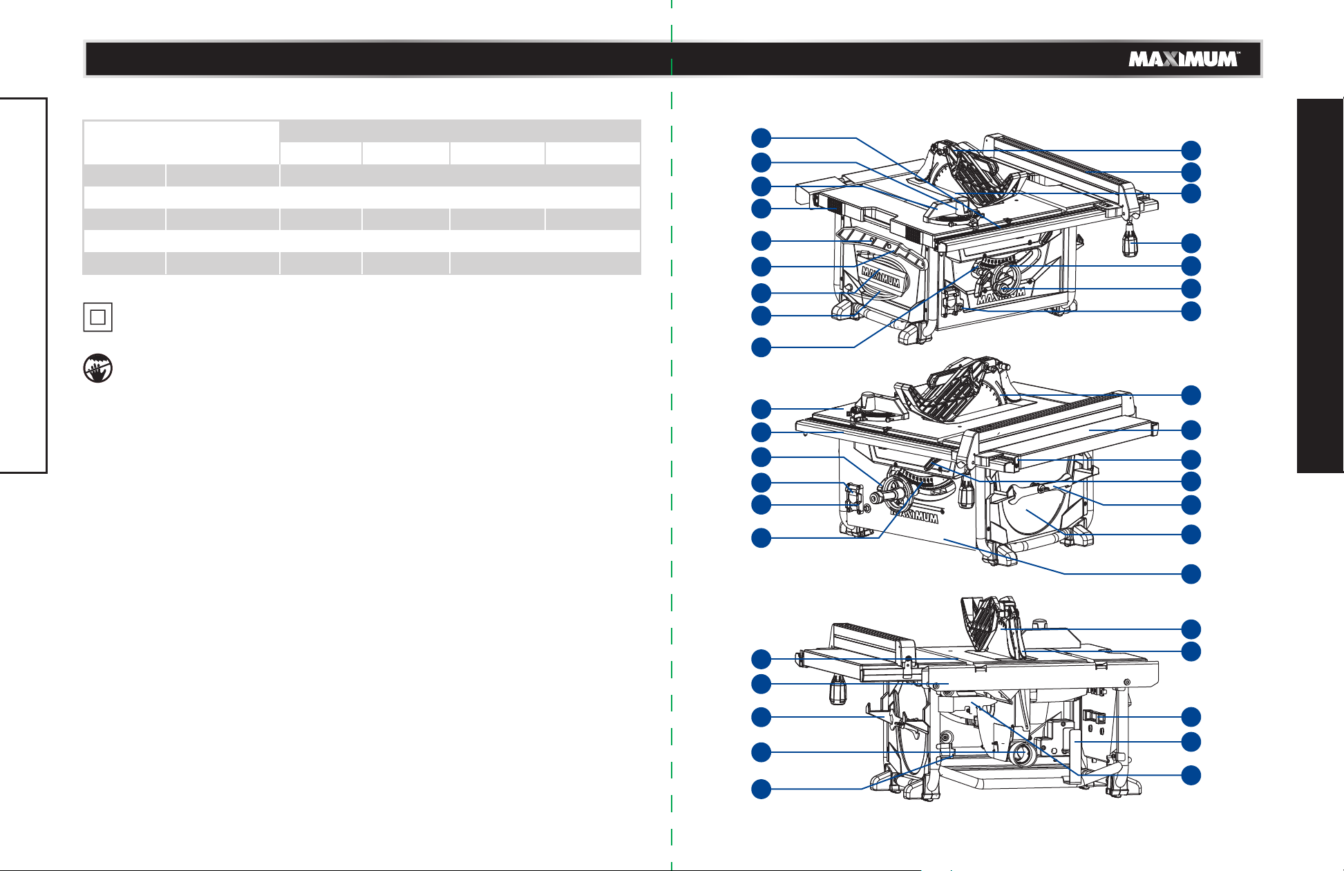
In the event of a malfunction or breakdown, grounding provides a path of least resistance
for electric current to reduce the risk of electric shock. This tool is equipped with an
electric cord having an equipment-grounding conductor and a grounding plug. The plug
must be plugged into a matching outlet that is properly installed and grounded in
accordance with all local codes and ordinances.
Do not modify the plug provided. If it will not fit the outlet, have the proper outlet
installed by a qualified electrician.
Improper connection of the equipment-grounding
conductor can result in a risk of electric shock. The
SAFETY GUIDELINES
conductor with a green outer surface, with or
without yellow stripes, is the equipment-grounding
conductor. If repair or replacement of the electric
cord or plug is necessary, do not connect the
equipment-grounding conductor to a live terminal.
Check with a qualified electrician or service
technician if the grounding instructions are not
completely understood, or if in doubt as to whether
the tool is properly grounded. Use only three-wire
extension cords that have three-prong grounding plugs and three-pole receptacles that
accept the tool's plug, as shown. Repair or replace a damaged or worn cord immediately.
GROUNDING INSTRUCTIONS:
• Make sure the extension cord is in good condition. When using an extension cord, be
sure to use one that is heavy enough to carry the current that your product will draw.
An undersized cord will cause a drop in line voltage, which will result in loss of power
and overheating. The table on the next page shows the correct size to be used
according to cord length and nameplate ampere rating. When in doubt, use the next
heavier gauge. The smaller the gauge number, the heavier the cord.
• Make sure your extension cord is properly wired and in good condition. Always replace
a damaged extension cord, or have it repaired by a qualified person before using it.
Protect your extension cords from sharp objects, excessive heat, and damp or wet areas.
• Use a separate electrical circuit for your tools. This circuit must consist of not less than
#12 wire with a 20 A time-delayed fuse or a #14 wire with a 15 A time-delayed fuse.
Before connecting the motor to the power line, make sure the switch is in the Off
position and the electric current is rated the same as the current stamped on the motor
nameplate. Running at a lower voltage will damage the motor.
Three-prong plug
SAFETY GUIDELINES
Grounding prong
Properly grounded
outlet
CAUTION!
• In all cases, verify that the outlet in question is properly
grounded. if you are not sure, have a licensed electrician
check the outlet.
WARNING!
• Use the proper extension cord. Make sure to use an
extension cord that is heavy enough to carry the current
required by the tool. An undersized cord will cause a drop
in line voltage, resulting in loss of power and overheating
of the tool.
• Use the extension cord only for intended purpose. Do not
pull the extension cord to remove it from the power socket.
WARNING!
• This tool must be grounded while in use in order to
protect the operator from electric shock.
NOTE: Recycle unwanted materials rather than disposing of them as
waste. Sort the tool and its components in specific categories and
take to the local recycling centre or dispose of them in an
environmentally safe way.
Page 7
12
model no. 055-6766-2 | contact us 1-888-670-6682
model no. 055-6766-2 | contact us 1-888-670-6682
Recommended size for extension cords
13
AMPERAGE RATING OF THE TOOL
(120 V CIRCUIT ONLY)
MORE THAN
0
6
10
12
Double-insulated construction.
Danger, keep hands away from blade.
NOT MORE THAN
6
10
12
16
SAFETY GUIDELINES
TOTAL LENGTH OF THE EXTENSION CORD
25' (7.6 m)
MINIMUM GAUGE FOR THE EXTENSION CORD (AWG)
18
18
16
14
50' (15.2 m)
16
16
16
12
100' (30.5 m)
16
14
14
Not recommended
150' (45.7 m)
14
12
12
38
37
36
35
34
33
32
31
30
29
28
27
26
25
2
3
4
5
6
7
8
9
10
11
12
1
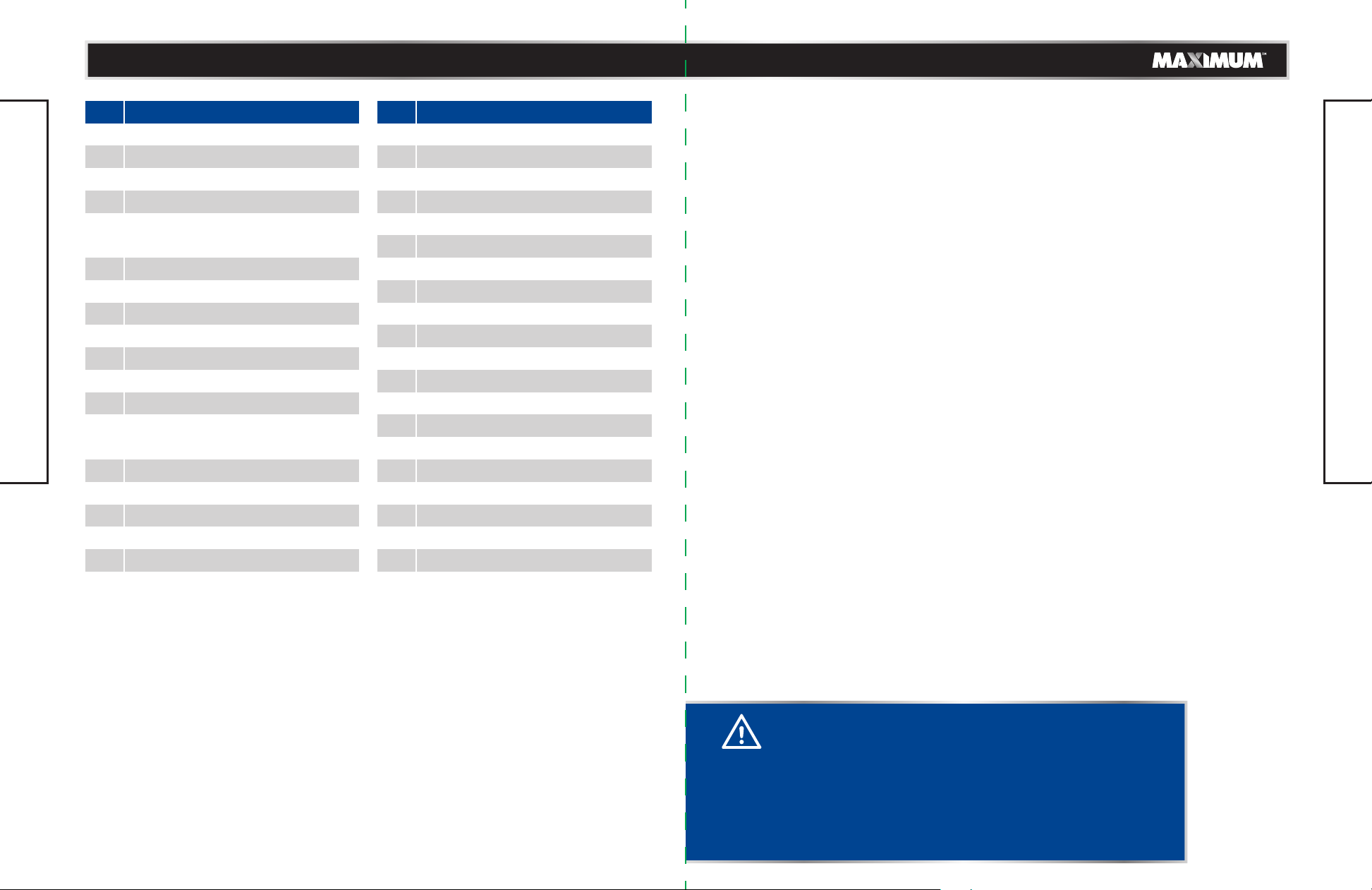
KNOW YOUR TABLE SAW
24
23
22
21
20
19
13
14
15
16
17
18
18
Page 8
14
model no. 055-6766-2 | contact us 1-888-670-6682
model no. 055-6766-2 | contact us 1-888-670-6682
15
No.
Description
1
Blade guard
2
Rip fence
3
Table insert
4
Rip fence locking handle
5
Height/bevel adjusting
handwheel
6
Height adjustment knob
7
Overload reset switch
8
Riving knife
9
Sliding extension table
10
Rapid position block
11
Extension table locking lever
12
Blade wrench
13
Saw blade and blade wrench
KNOW YOUR TABLE SAW
ANTI-KICKBACK PAWLS
Kickback is a hazard in which the workpiece is thrown back toward the operator. The
teeth on the anti-kickback pawls point away from the workpiece. If the workpiece should
be pulled back toward the operator, the teeth dig into the wood to help prevent or
reduce the possibility of kickback.
BEVEL SCALE AND BEVEL INDICATOR
The easy-to-read scale and indicator on the front of the cabinet shows the exact blade
angle.
BLADE GUARD
The guard is installed over the riving knife. It protects the operator’s hand from being cut
while providing a clear view of the material to be cut during through-sawing cuts.
BEVEL-LOCKING LEVER
This lever, under the work table surface on the front of the cabinet, locks the angle
setting of the blade.
storage
14
Cabinet
15
Saw blade
16
Anti-kickback pawls
17
Mitre gauge storage
18
Blade guard storage
No.
Description
19
Anti-kickback pawls storage
20
Dust extraction port
21
Rip fence storage
22
Outfeed support
23
Mitre gauge groove
24
Bevel scale
25
On/Off switch
26
Safety key
27
Bevel-locking lever
28
Front rail
29
Work table
30
Bevel indicator
31
Plug cable
32
Plug cable storage
33
Push stick
34
Push stick storage
35
Rubber mat
36
Mitre gauge
37
Mitre gauge locking handle
38
Scale
SAW BLADE
For maximum performance, it is recommended that you use the 40-tooth, 10" (25.4 cm)
carbide-tipped combination blade provided with your saw. The blade is raised and
lowered with the height/bevel adjusting handwheel. Bevel angles are locked with the
bevel-locking lever.
HEIGHT/BEVEL ADJUSTING HANDWHEEL
Located on the front of the cabinet, this handwheel is used to lower and raise the blade
for adjustments or blade replacement. The handwheel also makes the adjustment for
bevel angles easy.
RIP FENCE LOCKING HANDLE
The handle on the front of the rip fence releases or locks the rip fence with respect to the
work table.
EXTENSION TABLE LOCKING LEVER
This lever, under the work table surface, locks the right extension table.
RUBBER MAT
To better protect the left side of the work table with rubber feet when storing the table
saw vertically.
RAPID POSITION BLOCK
Rapidly set the rip fence to 14” (355.6 mm) on the right rail with it, and more easily read
the extended length.
MITRE GAUGE
This mitre gauge aligns the wood for a cross cut. The easy-to-read indicator shows the
exact angle for a mitre cut.
MITRE GAUGE GROOVES
The mitre gauge rides in these grooves on either side of the blade.
FRONT RAIL
Front rail provides support for the rip fence.
WARNING!
• Use only 10" (25.4 cm) diameter blades rated at maximum
safe operating speeds of 3500 RPM or higher. Failure to
heed this warning could result in personal injury.
• The blades should always be kept sharp. Use a reputable
sharpening service to sharpen the blades when needed.
• Never store the blades stacked on top of one another.
Place material such as cardboard between them to keep
the blades from coming into contact with one another.
KNOW YOUR TABLE SAW
Page 9
16
model no. 055-6766-2 | contact us 1-888-670-6682model no. 055-6766-2 | contact us 1-888-670-6682
17
RIP FENCE
The rip fence is a sturdy metal fence that can be locked to the work table to guide the
workpiece securely.
SCALE
Located on the front rail, the easy-to-read scale provides precise measurements for rip
cuts.
RIVING KNIFE
The riving knife is a metal piece, slightly thinner than the saw blade, used to keep the kerf
open to prevent kickback.
SWITCH ASSEMBLY
This saw has an easy-access power switch. The switch located on the front of the cabinet
allows the operator to turn the table saw On/Off easily. To lock the switch in the Off
position, remove the safety key from the switch. Place the key in a location that is
inaccessible to children and others not qualified to use the tool.
ARBOUR
The arbour is a shaft on which a blade is mounted.
KNOW YOUR TABLE SAW
WORK TABLE
The surface to which the workpiece is attached while cutting.
OVERLOAD PROTECTION
The machine is equipped with a overload reset switch that will restart the motor after it
shuts off due to overloading or low voltage. If the motor stops during operation, move
the ON/OFF switch to the “OFF ” position. Remove any workpiece from the table. Wait
about 5 minutes for the motor to cool down, and then push the reset button and move
the switch to the “ON” position.
WOODEN SPACER
The wooden spacer is attached on one side of the rip fence to prevent the material from
being caught between the bottom of the rip fence and the work table, when ripping
material such as thin panelling.
OUTFEED SUPPORT
This outfeed support at the back of the tool gives the operator additional support when
cutting long workpieces.
SLIDING EXTENSION TABLE
Located on right side of the saw table, this extension table givers the operator additional
support when cutting wide workpieces.
OPERATING COMPONENTS
The upper portion of the blade projects up through the table and is surrounded by an
insert called the table insert. The height of the blade is set with a handwheel on the front
of the cabinet.
Detailed instructions are provided in the “Operating Instructions” section of this manual
for the basic cuts: cross cuts, mitre cuts, bevel cuts and compound cuts.
The rip fence is used to position work for lengthwise cuts. A scale on the front rail shows
the distance between the rip fence and the blade.
It is very important to use the blade guard assembly for all through-sawing operations.
The blade guard assembly includes: riving knife, anti-kickback pawls, and plastic blade
guard.
APPLICATIONS
You can use this tool for the purposes listed below:
• Straight-line cutting operations such as crosscutting, ripping, mitring 0-45° mitre
angle, bevel crosscutting 0-45° blade bevel and 90° mitre angle and 0-45° blade bevel
and 0-45° mitre angle.
• Cabinet making and woodworking.
CAUSES OF KICKBACK
Kickback can occur when the blade stalls or binds, causing the workpiece to be kicked
back toward the operator with great force and speed. If your hands are near the saw
blade, they may be jerked loose from the workpiece and come into contact with the
blade. Obviously, kickback can cause serious injury, and it is well worth using precautions
to avoid the risks.
Kickback can be caused by any action that pinches the blade in the wood, such as the
following:
• Making a cut with incorrect blade depth.
• Sawing into knots or nails in the workpiece.
• Twisting the wood while making a cut.
• Failing to support the workpiece.
• Forcing a cut.
• Cutting warped or wet lumber.
• Using the wrong blade for the type of cut.
• Not following correct operating procedures.
• Misusing the saw.
• Failing to use the anti-kickback pawls.
• Cutting with a dull, gummed-up, or improperly set blade.
AVOIDING KICKBACK
• Always use the correct blade depth setting. The top of the blade teeth should clear the
workpiece by 1/8 to 1/4" (3.2 to 6.4 mm).
NOTE: This table saw is designed to cut wood and wood composition
products only. Depending on the shape of the panel, use the rip fence
or mitre gauge.
KNOW YOUR TABLE SAW
Page 10
model no. 055-6766-2 | contact us 1-888-670-6682model no. 055-6766-2 | contact us 1-888-670-6682
1918
• Inspect the workpiece for knots or nails before beginning a cut. Knock out any loose
knots with a hammer. Never saw into a loose knot or nail.
• Always use the rip fence when rip cutting and the mitre gauge when crosscutting. This
helps to prevent twisting the wood in the cut.
• Always use clean, sharp, and properly set blades. Never make cuts with dull blades.
• To avoid pinching the blade, support the work properly before beginning a cut.
• When making a cut, use steady, even pressure. Never force cuts.
• Do not cut wet or warped lumber.
• Always hold the workpiece firmly with both hands or with push sticks. Keep your body
in a balanced position to be ready to resist kickback should it occur. Never stand
directly in line with the blade.
• Use the right type of blade for the cut being made.
KNOW YOUR TABLE SAW
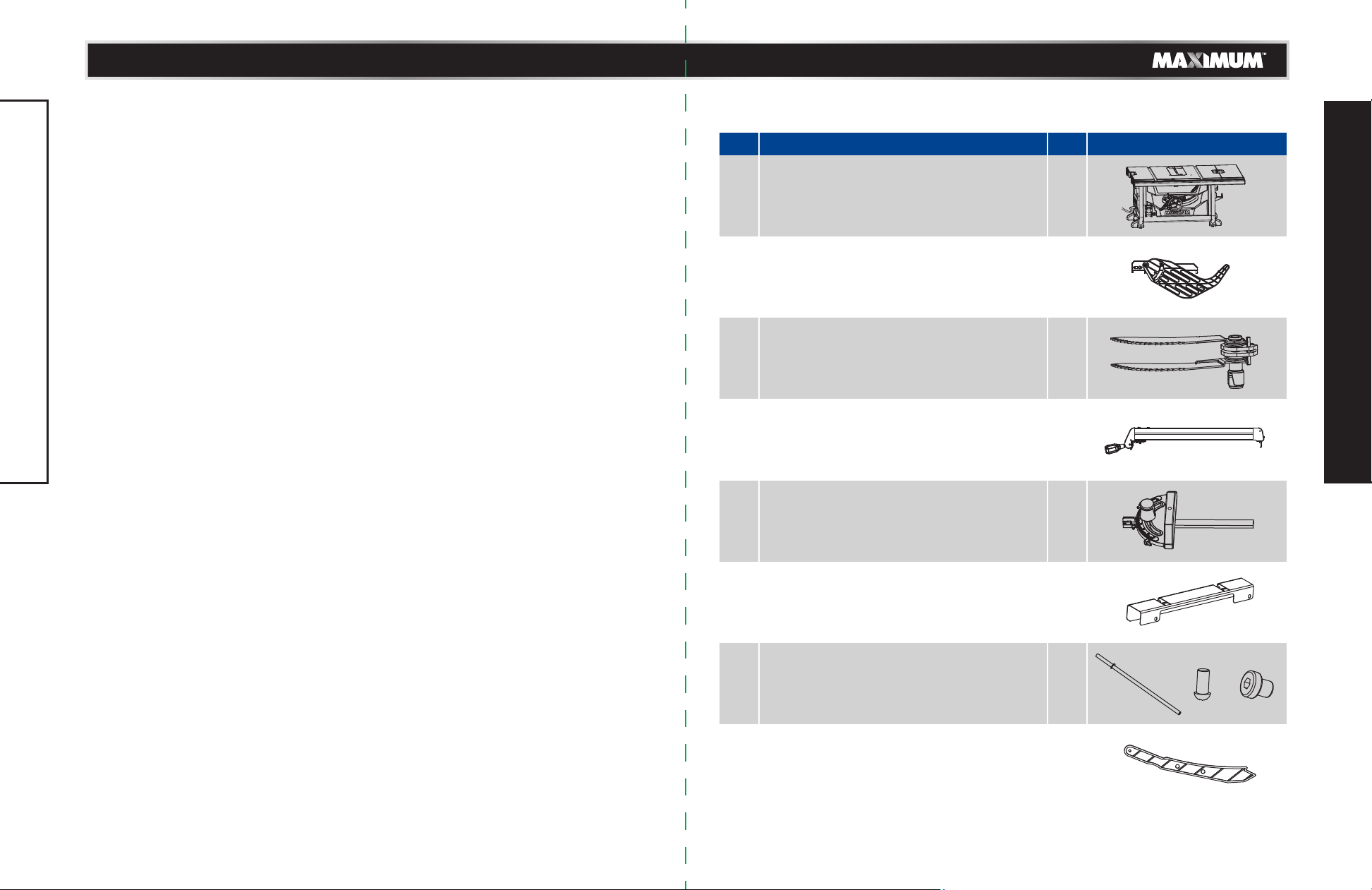
PACKAGE CONTENTS
No. Description Qty Illustration
Table saw assembly
1
Blade guard assembly
2
Anti-kickback pawls assembly
3
Rip fence
4
Mitre gauge
5
1
1
1
1
1
ASSEMBLY
Outfeed support
6
Extension poles, stop screws
7
and pole stopper bolts
Push stick
8
1
2
1
Page 11
20
model no. 055-6766-2 | contact us 1-888-670-6682
model no. 055-6766-2 | contact us 1-888-670-6682
21
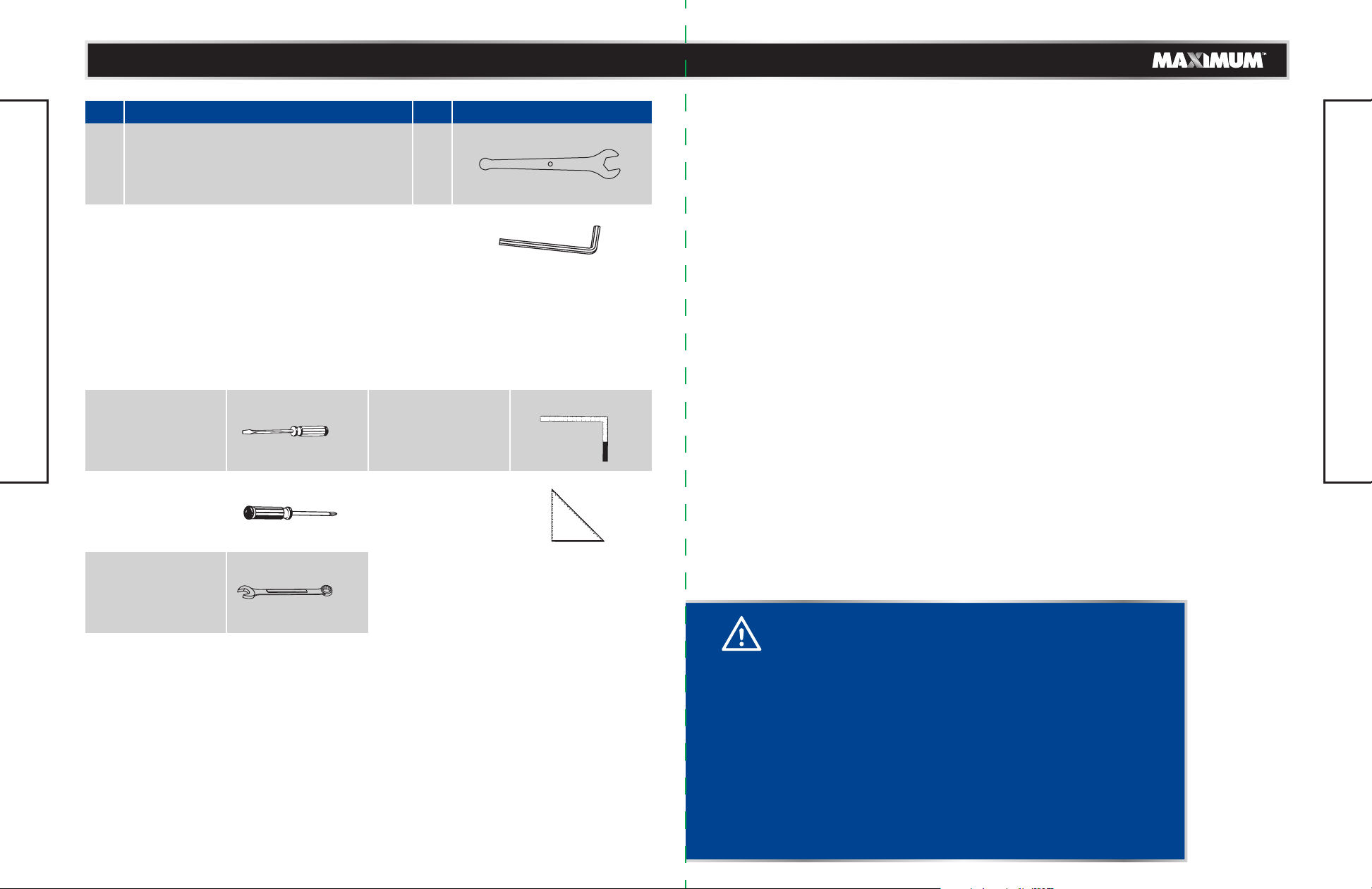
No. Description Qty Illustration
Blade wrenches
9
6 mm Hex key
10
TOOLS NEEDED FOR ASSEMBLY
Screwdriver Framing square
ASSEMBLY
Star-head screwdriver
2
1
Triangle square
UNPACKING
Do not use this product if any parts of the package contents are already assembled to
your product when you unpack it. Package contents are not assembled to the product by
the manufacturer and require customer installation. Use of a product that may have been
improperly assembled could result in serious personal injury.
• Carefully remove the table saw from the carton and remove the protective polyfoam
from around the motor.
• Inspect the tool carefully to make sure no breakage or damage occurred during
shipping.
• Do not discard the packing material until you have carefully inspected and satisfactorily
operated the tool.
• The saw is factory set for accurate cutting. After assembling it, check for accuracy. If
shipping has influenced the settings, refer to specific procedures explained in this
manual.
• If any parts are damaged or missing, please call 1-888-670-6682 for assistance.
ASSEMBLY
Wrench
WARNING!
• If any parts are damaged or missing, do not operate this
tool until the parts are replaced. Use of this product with
damaged or missing parts could result in serious personal
injury.
• Do not attempt to modify this tool or create accessories not
recommended for use with this tool. Any such alteration or
modification is misuse and could result in a hazardous
condition leading to possible serious personal injury.
• Do not connect to power supply until assembly is complete.
Failure to comply could result in accidental starting and
possible serious personal injury.
• Risk of injury! Always pull out the mains plug (disconnect
the product from its power supply) before commencing
work on the product.
Page 12
22
model no. 055-6766-2 | contact us 1-888-670-6682
model no. 055-6766-2 | contact us 1-888-670-6682
23
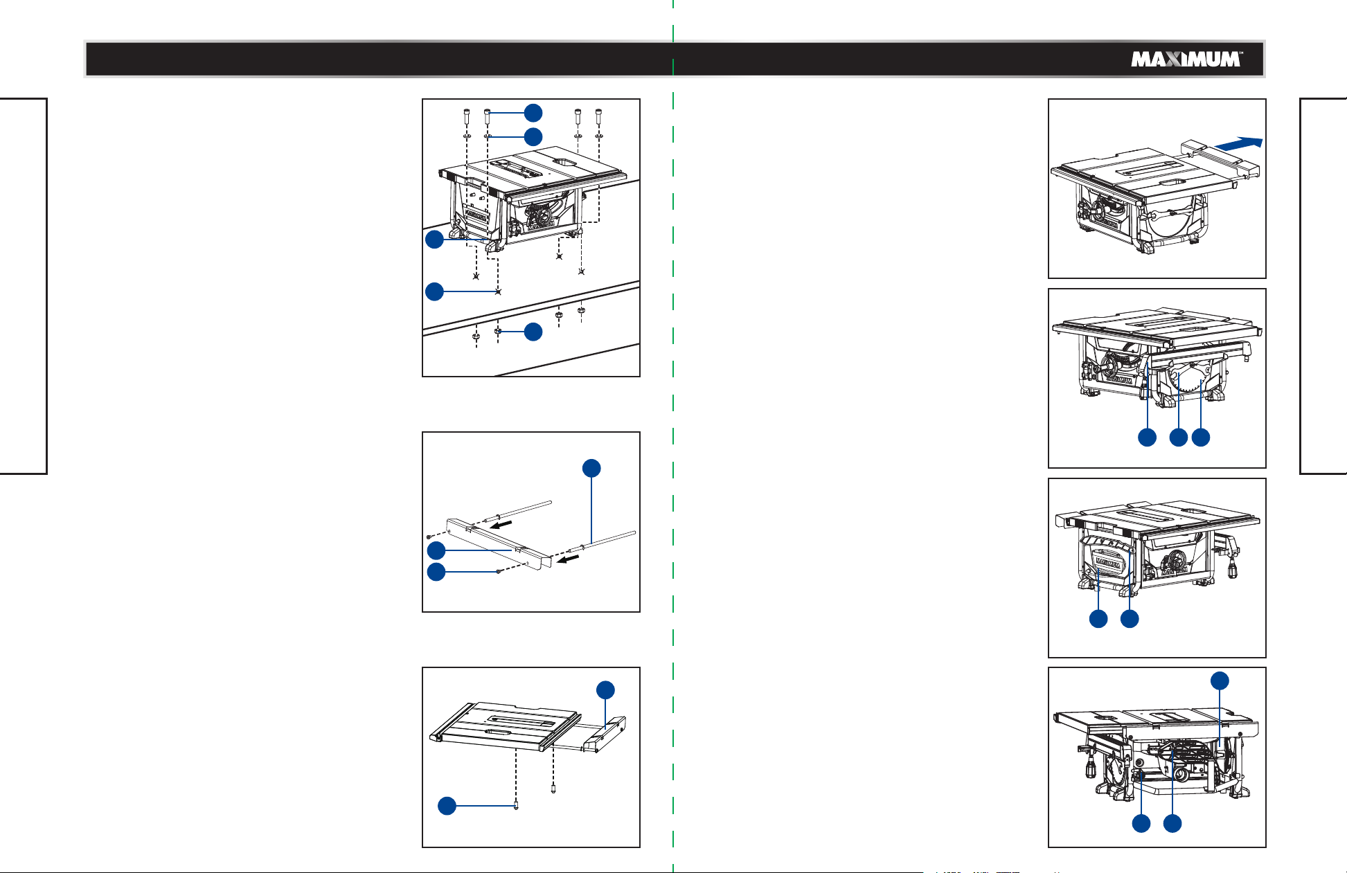
MOUNTING HOLES (Fig. 1)
The table saw must be mounted to a firm, supporting,
waist-high surface such as a workbench or leg stand.
• If mounting to a workbench, the base should be
bolted securely using 5/16" (8 mm) hex bolts (not
included) through mounting holes (1).
Bolts should be of sufficient length to accommodate
the tube frame, flat washers, hex nuts, and the
thickness of the workbench.
• Locate and mark where the saw is to be mounted,
relative to holes in the tube frame of the tool.
• Drill four 3/8" (9.5 mm) diameter holes (2) through
workbench.
• Place table saw on workbench aligning holes in
tube frame and with holes drilled in workbench.
• Insert four 5/16" (8 mm) dia. bolts (3) through
holes in tube frame, plastic septa and supporting
surface; then secure with 5/16" (8 mm) flat washers
(4) and 5/16" (8 mm) hex nuts (5).
Carefully check the workbench after mounting to
make sure that no movement can occur during use.
ASSEMBLY
If any tipping, sliding, or walking is noted, secure the
workbench to the floor before operating.
INSTALLING THE OUTFEED SUPPORT (Fig. 2-3)
• Insert the extension table poles (1) into the two
holes of the outfeed support (2) and tighen the
pole stopper bolts (3).
• Insert the extension table poles (1) into the two
holes in the rear of the work table and into the
extension tube brackets that are located under the
work table. Position the outfeed support.
• Thread the two stop screws (4) into the holes
located on ends of the rear table extension
poles (1) and tighten them.
3
4
1
2
5
Fig. 1
1
2
3
Fig. 2
TO USE THE OUTFEED SUPPORT (Fig. 4)
The outfeed support slides to give the operator
additional for cutting long workpieces.
• With the table saw in the off position, stand behind
the saw.
• Grasp the outfeed support with both hands and pull
it until it is fully extended.
TO STORE THE TABLE SAW ACCESSORIES
(Fig. 5-7)
The table saw has four convenient storage areas
(one on either side of the saw cabinet, one on the
back of the saw. and one on inside of the right saw
cabinet) specifically designed for the saw’s
accessories: saw blade (1), blade wrench (2), rip
fence (3), push stick (4), plug cable (5), mitre
gauge (6), blade guard (7), and anti-kickback pawls
(8).
When not in use, store accessories securely.
Fig. 4
3 2 1
Fig. 5
4
5
Fig. 6
ASSEMBLY
2
4
7
Fig. 3
8
6
Fig. 7
Page 13
model no. 055-6766-2 | contact us 1-888-670-6682
model no. 055-6766-2 | contact us 1-888-670-6682
2524
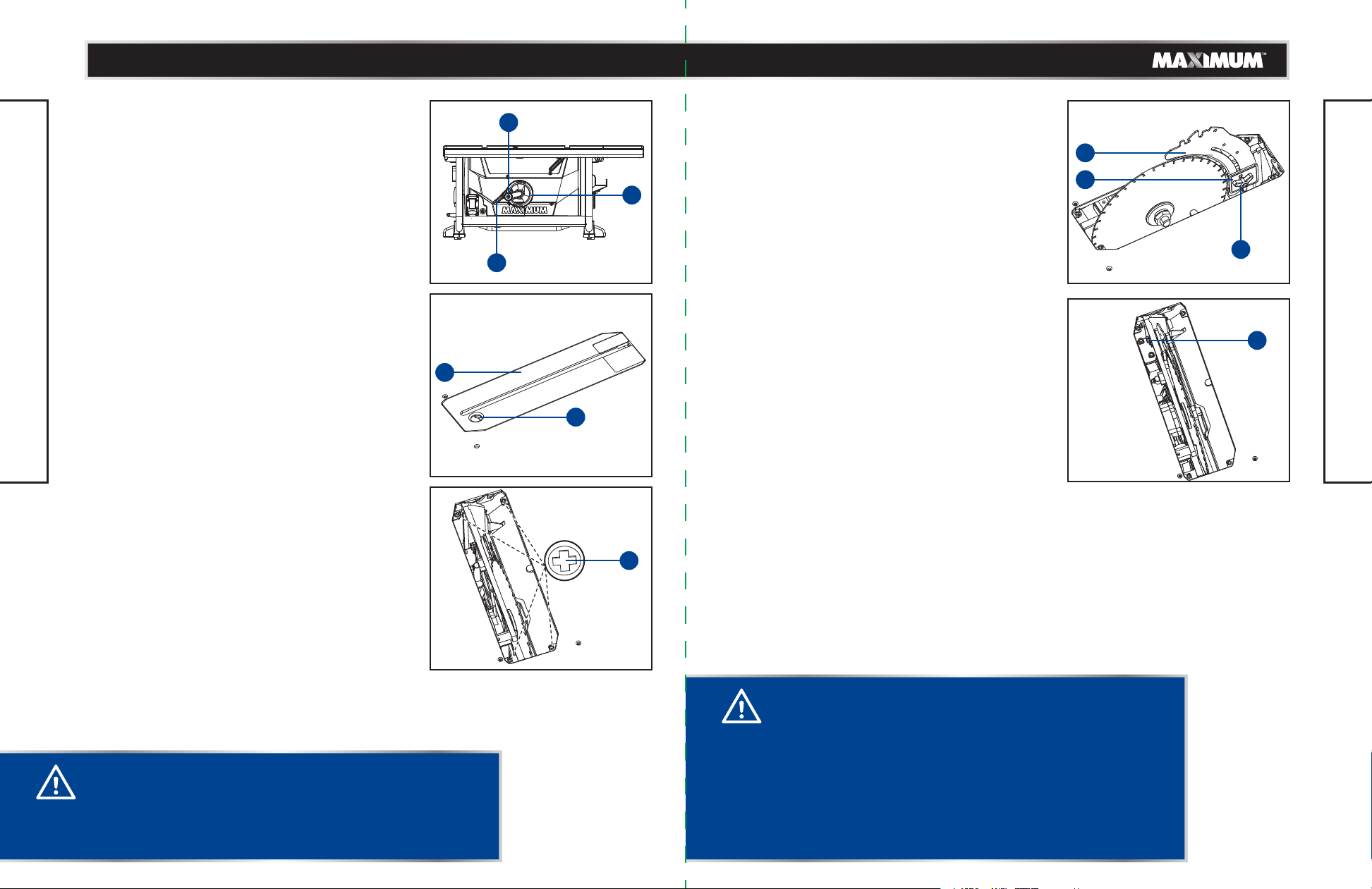
HEIGHT/BEVEL ADJUSTING HANDWHEEL
(Fig. 8)
• Turn the height adjusting knob (1) clockwise to
raise the blade, and counter-clockwise to lower the
blade.
• Turn the handwheel (2) clockwise, and move along
the arc rail, then the blade will bevel from 0-45°, or
turn counter-clockwise.
• Secure the blade bevel-locking lever (3) when the
bevel angle pointer points at desired angle on
scale. To lock the blade, turn blade bevel-lock lever
clockwise. To unlock the blade, turn it counter clockwise.
TO REMOVE/REPLACE/ALIGN THE TABLE
INSERT (Fig. 9-10)
• Turn the height adjusting knob counter-clockwise
to lower the blade to lowermost position.
• Lock the blade by turning bevel-lock lever
clockwise.
ASSEMBLY
• To remove the table insert: Place your index finger
in the hole and push the locking tab (1) back,
pulling the table insert (2) out toward the front of
the saw.
• To reinstall the table insert: Push the locking tab (1)
back, and at the same time push the table insert (2)
down to secure in place.
When the table insert is not level with the saw blade,
using a screwdriver, adjust the four set screws (3)
under the table insert until the table insert is lever
with the saw table.
1
2
3
2
1
Fig. 9
3
ADJUSTING THE RIVING KNIFE (Fig. 11-13)
This saw is shipped with the riving knife placed in
“down” position.
• Unplug the saw.
TO PLACE IN THE HIGHEST POSITION (THE LOWEST
HOLE IN THE RIVING KNIFE) FOR ALL THROUGH
CUTS (WITH BLADE GUARD AND ANTI-KICKBACK
PAWLS):
• Remove the table insert.
• Set the saw blade angle to 0°.
• Raise the saw blade to the uppermost positon by
turning the height adjusting knob clockwise.
• Loosen the tri-wing knob (1) to allow approximately
1/8" (3.2 mm) gap between riving knife (2) and lock
plate (3).
• Push the lock knob (4) to the riving knife (2) until
the riving knife (2) unlocks from the locking pin.
• Loosen the lock knob (4) and pull riving knife (2)
up or down until the pin is re-engaged and the
riving knife is in the highest position.
• Tighten the tri-wing knob (1).
• Reinstall the table insert.
TO PLACE IN THE MIDDLE POSITION (THE MIDDLE
HOLE IN THE RIVING KNIFE) FOR NON-THROUGH
CUTS, EG. RABBETS (WITH BLADE GUARD AND
ANTI-KICKBACK PAWLS REMOVED):
• Remove the table insert.
• Set the saw blade angle to 0°.
• Raise the saw blade to the uppermost positon by
turning the height-adjusting knob clockwise.
2
3
1
Fig. 11Fig. 8
4
ASSEMBLY
Fig. 12
WARNING!
The table insert must be level with the saw table. If the table
insert is too high or too low, the workpiece can catch on the
uneven edges, resulting in binding or kickback, which could
result in serious personal injury.
Fig. 10
WARNING!
Riving knife has three holes for three positions. The highest
position is for all through cuts. The middle position is for
rabbets and other non-through cuts, (with blade guard and
anti-kickback pawls removed). The lowest position is only for
shipping.
• Make sure locking pin is aligned with riving knife hole and
secured in position by tightening the tri-wing knob.
• Riving knife must be in line with blade. Make sure riving
knife sits flat against mounting bracket and lock plate.
Page 14
model no. 055-6766-2 | contact us 1-888-670-6682
model no. 055-6766-2 | contact us 1-888-670-6682
2726
• Loosen the tri-wing knob (1) to allow approximately
1/8" (3.2 mm) gap between riving knife (2) and lock
plate (3).
• Push the lock knob (4) to the riving knife (2) until
the riving knife (2) unlocks from the locking pin.
• Loosen the lock knob (4) and pull riving knife (2) up
or down until the pin is reengaged and the riving
knife is in the middle position.
• Tighten the tri-wing knob (1).
• Reinstall the table insert.
PLACE IN THE LOWEST POSITION (THE UPPER
HOLE IN THE RIVING KINIFE) ONLY FOR SHIPPING
TO INSTALL THE ANTI-KICKBACK PAWLS AND
BLADE GUARD (Fig. 14-18)
• Unplug the saw.
• Set the blade angle to 0°.
• Raise the saw blade to maximum height by turning
height adjustment knob clockwise.
• Place the riving knife in the highest position.
ASSEMBLY
TO INSTALL ANTI-KICKBACK PAWLS: (Fig. 14-15)
• Unplug the saw.
• Pull out and hold knob (1) and push anti-kickback
pawls down, remove it from the anti-backpawls
storage (2) at the bottom left rear side of the saw.
(Fig. 14)
• Pull out and hold knob (1). Place the spring pin (3)
on the anti-kickback pawls (4) into the notch (5)
indicated on the riving knife (6).
• Press anti-kickback pawls assembly completely
down and push spring pin down to secure in
position.
• Release knob (1) to insert the pin (7) into hole (8)
indicated on the riving knife (6).
IN UP POSITION FOR
THROUGH CUTTING
IN MIDDLE POSITION FOR
NON-THROUGH CUTTING
a
1
Fig. 13
2
TO INSTALL THE BLADE GUARD: (Fig. 16-17)
• Unplug the saw.
• Hold the knobs (9) (one on either side of the blade
guard) and push the knobs forward to the front of
the blade guard and down until the pin comes out
from the notch in the mounting bracket (blade
guard storage I) (10) at top left rear side of the saw,
then raise the blade guard up from the U-bracket
(blade guard storage II) (11) at bottom right rear
side of the saw and remove the blade guard from
the blade guard storage. (Fig. 16)
• Hold and push knobs (9) forward to the front of the
the blade guard. Place the pin (12) on the blade
guard (13) into the notch (14) indicated on the riving
knife (6).
• Pull blade guard fully back onto riving knife. Push
pin and release it to lock guard into position.
Make sure that blade guard body is parallel to the
table. If it is not, adjust the set screw (15) as
necessary. (Fig. 18)
3
4
7
8
9
9
12
9
6
10
b
1
5
6
Fig. 15
a
c
11
Fig. 16
13
14
Fig. 17
ASSEMBLY
NOTE: Anti-kickback pawls should only be installed for through cuts.
b
Fig. 14
15
Fig. 18
Page 15
model no. 055-6766-2 | contact us 1-888-670-6682
model no. 055-6766-2 | contact us 1-888-670-6682
2928
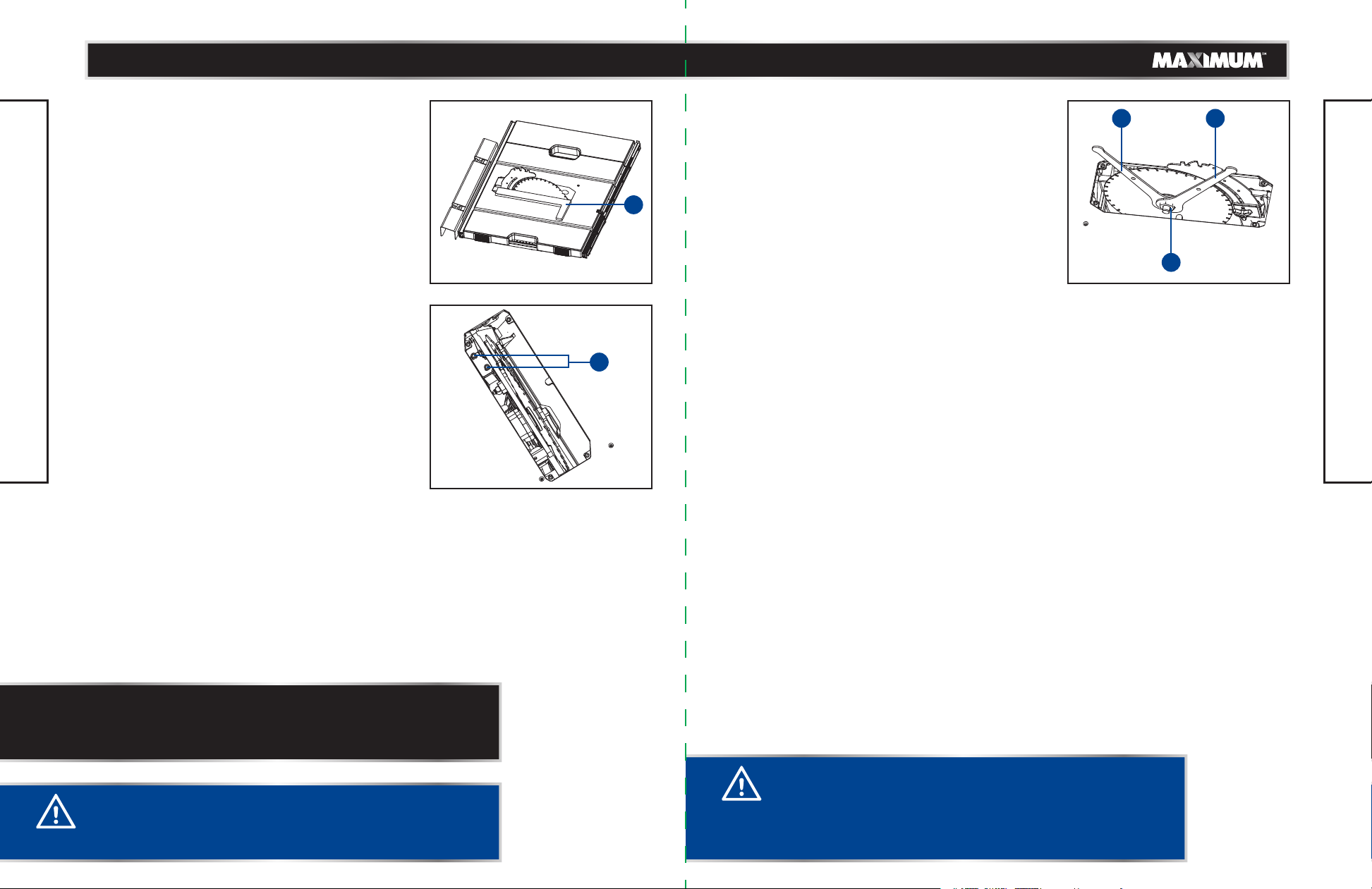
CHECK AND ALIGN THE RIVING KNIFE AND
SAW BLADE (Fig. 19-20)
TO CHECK THE ALIGNMENT OF THE RIVING KNIFE:
• Unplug the saw.
• Raise the saw blade as high as it will go by turning
the height-adjusting knob clockwise.
• Remove the anti-kickback pawls, place a framing
square (1) or straight edge against both the saw
blade and the riving knife.
Make sure that you place the framing square
between the carbide teeth, and measure from the
blade. This step will ensure that the framing square
is square against the blade from the front to the
back of the blade.
• The saw blade and riving knife are aligned when
the framing square contacts the blade and the
riving knife evenly, with no gaps.
TO ADJUST:
ASSEMBLY
• Unplug the saw.
• Remove the table insert.
• Loosen the socket head bolts (2) that hold the
mounting bracket.
• Reposition the blade guard assembly left or right,
as required in order to align the riving knife with
the saw blade.
• Once properly aligned, securely retighten the
socket head bolts.
2
Fig. 20
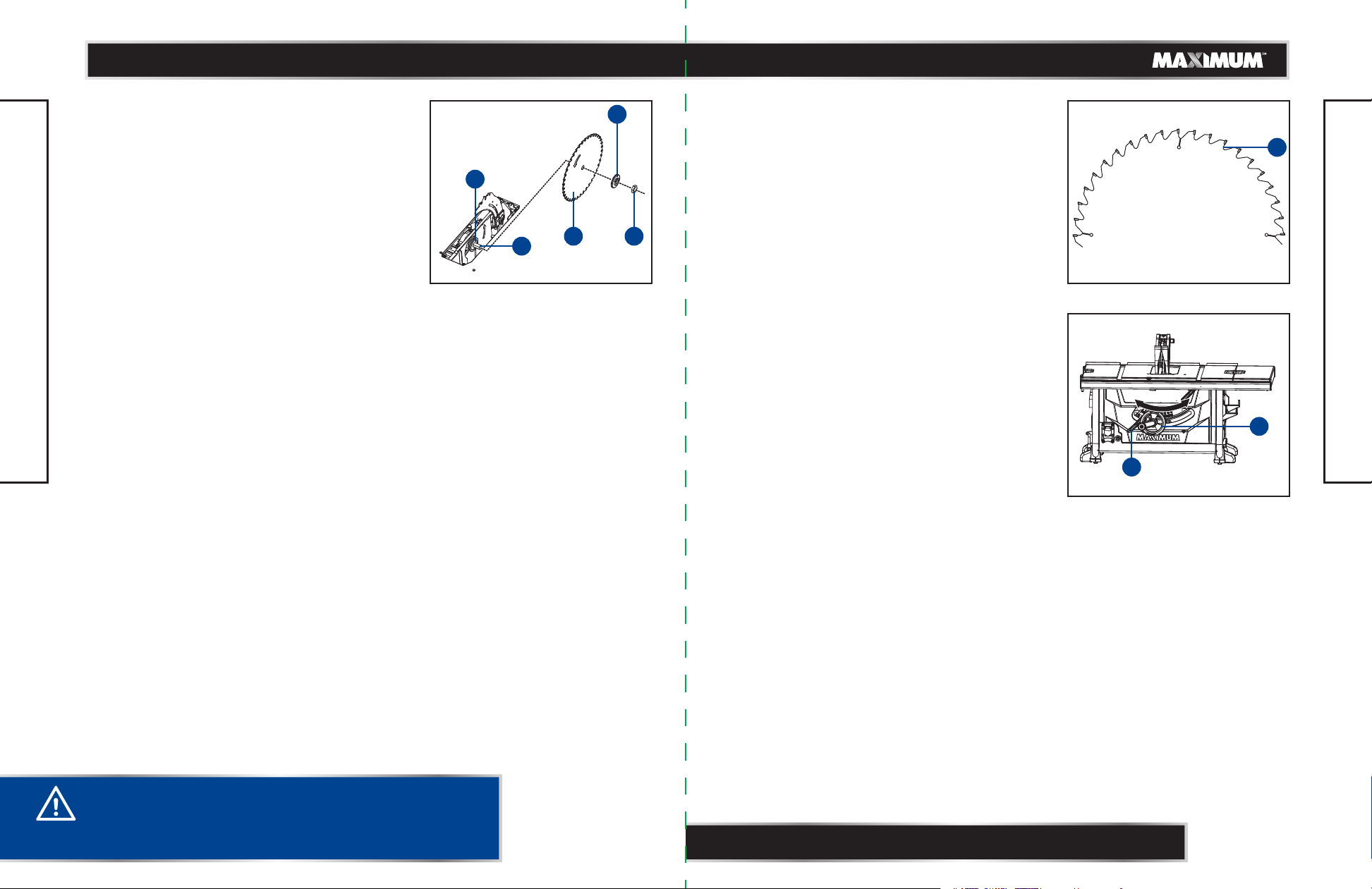
TO CHECK SAW BLADE INSTALLATION (Fig. 21)
The saw is shipped with the blade installed. Prior to
initial use, it is recommended that you check the
blade installation as instructed below.
• Unplug the saw.
1
• Remove the blade guard and anti-kickback pawls.
• Lower the saw blade and remove the table insert.
• Set the saw blade angle to 0°.
• Turn the bevel-locking lever clockwise to tighten it
securely. Raise the saw blade to its full height by
turning the height-adjusting knob clockwise.
TO LOOSEN THE BLADE:
• Using one opened-ended blade wrench (1), place
the flat open end on the flats on the outer blade
flange.
• Using the other opened-ended blade wrench (2),
place the flat open end on the flats on the arbour
nut (3). Holding both wrenches firmly, pull the
opened-ended blade wrench on the arbour nut
forward to the front of the machine.
TO TIGHTEN THE BLADE:
• Using one opened-ended blade wrench (1), place
the flat open end on the flats on the outer blade
flange.
• Using the other opened-ended blade wrench (2),
place the flat open end on the flats on the arbour
nut (3). Holding both wrenches firmly, pull the
opened-ended blade wrench (2) on the arbour nut
forward to the back of the machine. Make sure the
arbour nut is securely tightened. Do not overtighten.
• Check all clearances for free blade rotation.
1 2
3
Fig. 21Fig. 19
ASSEMBLY
NOTE: If the riving knife is out of alignment with the saw blade,
adjustment is needed. The blade guard and riving kinfe must always
be correctly aligned so that the cut workpiece will pass on either
side of the riving knife without binding or twisting to the side.
WARNING!
Improper riving knife alignment can cause kickback and
serious injury.
CAUTION!
To work properly, the saw blade teeth must point down
toward the front of the saw. Failure to heed this instruction
could cause damage to the saw blade, the saw or the
workpiece.
Page 16
model no. 055-6766-2 | contact us 1-888-670-6682
model no. 055-6766-2 | contact us 1-888-670-6682
3130
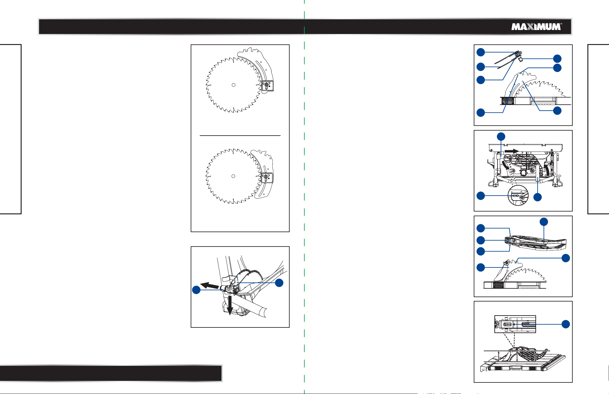
TO REPLACE THE SAW BLADE (Fig. 22)
When you need to replace the saw blade, please
follow the procedure below:
• Unplug the saw.
• Turn height-adjustment knob clockwise to raise
blade to maximum height.
• Remove the blade guard and anti-kickback pawls.
• Remove the table insert.
• Using one opened-ended blade wrench, place the
flat open end on the flats on the outer blade
flange (1).
• Using the other opened-ended blade wrench, place
the flat open end on the flats on the arbour nut (2).
Holding both wrenches firmly, pull the opened ended blade wrench on the arbour nut forward to
the front of the machine.
• Remove arbour nut (2), outer blade flange (1) and
saw blade (3).
• Place one new blade on arbour (4). Make sure saw
blade teeth point down at the front side of saw
ASSEMBLY
table. Place outer flange (1) and nut (2) on arbour
and use blade wrenches to tighten nut securely.
Verify that large, flat surface of the outer flange
faces the the saw blade and the saw blade (3) is
firmly seated aganist the inner flange (5).
• Lower the saw blade to lowest position and replace
table insert.
• Replace blade guard assembly and pawl assembly.
1
5
4
23
Fig. 22
CHANGING THE BLADE DEPTH (Fig. 23)
The saw blade depth should be set so that the outer
points of the saw blade are higher than the workpiece
by approximately 1/8 to 1/4" (3.2 to 6.4 mm), but the
lowest points (gullets) (1) are below the top surface.
• Unplug the saw.
• Turn the bevel-locking lever clockwise to tighten it
securely.
• Raise the blade by turning the height-adjusting
knob clockwise, or lower it by turning the knob
counter-clockwise.
1
Fig. 23
CHANGING THE BLADE ANGLE (Fig. 24)
This table saw has a rack-and-pinion bevel control
that allows you make angled cuts from 90° to 45°.
• Unplug the saw.
• Loosen the bevel-locking lever (1) by turning it
counter-clockwise.
• To adjust the bevel angle, turn the height/bevel
adjusting handwheel (2) counter-clockwise
increasing the angle of the blade and bringing it
closer to 45°. Turning it clockwise decreases the
angle, bringing the blade closer to 90°.
• Lock by turning the bevel-locking lever (1)
clockwise.
1
2
ASSEMBLY
Fig. 24
WARNING!
Be extremely careful when loosening arbour nut.
Keep firm grasp on both wrenches. Do not allow hands to
slip and contact blade.
NOTE: A 90° cut has a 0° bevel and a 45° cut has a 45° bevel.
Page 17
model no. 055-6766-2 | contact us 1-888-670-6682
model no. 055-6766-2 | contact us 1-888-670-6682
3332
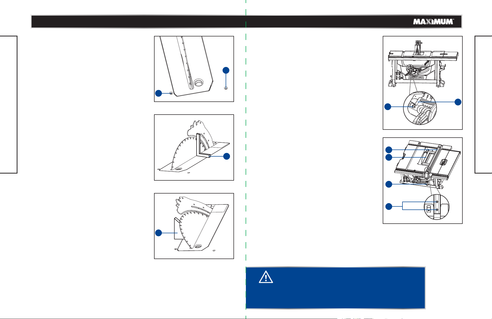
ADJUSTING THE BEVEL STOPS (Fig. 25-27)
This saw has positive stops that will quickly position
the saw blade at 90° or 45° to the table.
The angle settings of the saw have been set at the
factory and, unless damaged in shipping, should not
require setting during assembly. After extensive use,
it may need to be checked. Make adjustments only if
necessary.
• Unplug the saw.
• Remove the anti-kickback pawls assembly and
blade guard assembly.
• Raise the blade to the maximum height by turning
the height-adjusting knob clockwise.
• Using a framing square (1), set the blade to exactly
90°.
• If the blade stops bevelling before it gets to 90°,
loosen the 90°-stop set screw (2) (located at the
left of the table insert), and then adjust it to 90°.
• With the blade set at 90°, slowly turn the 90°-stop
set screw (2) until you feel resistance. Bevel the
ASSEMBLY
blade away from 90° a little, and then back to the
stop.
• Re-measure the angle and repeat the stop
adjustment as necessary until the blade stops at
90°.
• Set the 45° stop in the same way. The 45°-stop set
screw (3) is located at the right of table insert. Use
the triangle square (4).
• Replace the anti-kickback pawls assembly and
blade guard assembly.
• Make a test cut.
ADJUSTING THE BEVEL INDICATOR (Fig. 28)
If the bevel indicator (1) is not at 0° when the saw
blade is at 90°, adjust the indicator (1) by loosening
the cross screw (2) with a star-head screwdriver and
setting it to 0° on the bevel scale.
3
Retighten the cross screw (2).
Make sure that you make a trial cut on a scrap
piece of wood before making critical cuts. Measure
2
Fig. 25
1
Fig. 26
for exactness.
CHECKING THE ALIGNMENT OF THE RIP
FENCE TO THE BLADE (Fig. 29)
• Unplug the saw.
• Remove the blade guard assembly and anti-kickback
pawls assembly.
• Raise the locking handle (1) to allow the rip
fence (2) to be moved.
• Place the framing square (3) beside the blade, and
move the rip fence up to the square. Note the
measurement on the rip scale.
• Move the fence back and rotate the framing square
(3) 180° to check the other side.
• If the two measurements are not the same, loosen
the two socket head bolts (4) on the rip fence and
then align it.
• Retighten the two socket head bolts (4).
• Replace the blade guard assembly and anti-kickback
pawls assembly.
• Make two or three test cuts using scrap wood. If the
cuts are not true, repeat the process.
2
1
Fig. 28
2
3
ASSEMBLY
1
4
Fig. 29
4
Fig. 27
CAUTION!
To prevent personal injury:
• Always disconnect the plug from the power source when
making any adjustments.
• The adjustment must be correct. If it is not, kickback could
result in a serious injury and inability to make accurate cuts.
Page 18
model no. 055-6766-2 | contact us 1-888-670-6682
model no. 055-6766-2 | contact us 1-888-670-6682
3534
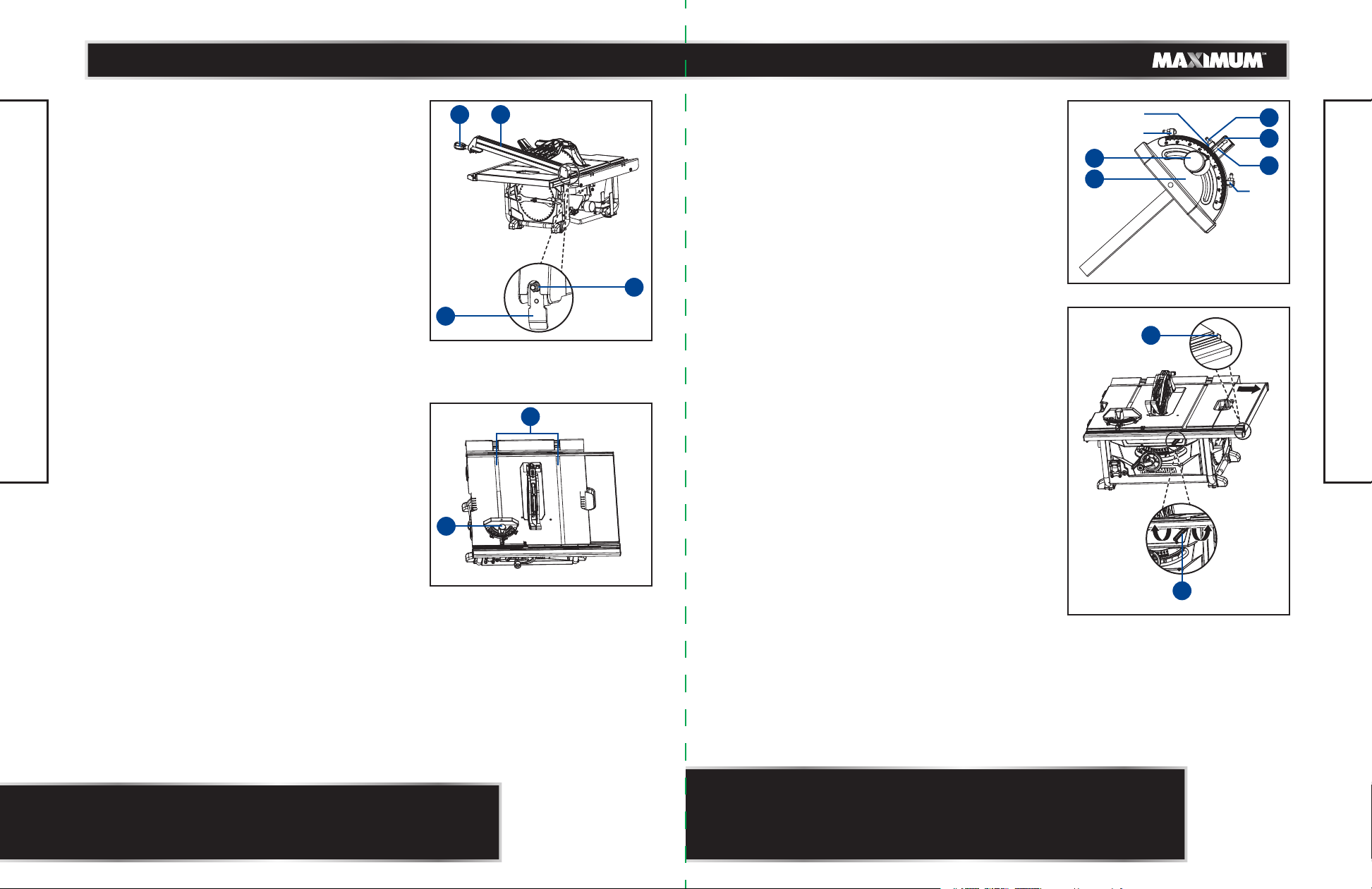
USING THE RIP FENCE (Fig. 30)
• Unplug the saw.
• Place the rear lip (1) of the rip fence (2) on the rear
of the saw table and push it slightly toward the
back of the unit.
• Lower the front end of the rip fence onto the guide
surfaces on top of the front rail.
• With the rip fence flat on the saw table, push the
fence toward the front rail to align the fence to the
saw table.
• Push the locking handle (3) down to align and
secure the fence.
Check for a smooth gliding action. If adjustments are
needed, see the previous section "Checking the
Alignment of the Rip Fence to the Blade."
• Make two or three test cuts using scrap wood. If
the cuts are not true, repeat the process.
USING THE MITRE GAUGE (Fig. 31)
ASSEMBLY
The mitre gauge provides greater accuracy in angled
cuts. For very close tolerances, test cuts are
recommended. There are two mitre gauge grooves,
one on either side of the saw blade. When making a
90° crosscut, use either mitre gauge groove. When
making a bevel crosscut (the blade tilted in relation
to the table), the mitre gauge should be located in
the groove on the right so that the blade is tilted
away from the mitre gauge and away from your
hands.
Mitre gauge supplied with saw is equipped with
individually adjustable index stops at 90° and 45°,
right and left, and can be manually adjusted up to
60° right and left.
• Slide the mitre gauge in the mitre gauge groove (1).
• Loosen the locking handle (2).
• With the mitre gauge in the mitre gauge groove,
rotate the gauge until the desired angle is reached
on the scale.
• Retighten the locking handle (2).
3 2
1
2
4
Fig. 30
TO ADJUST MITRE GAUGE (Fig. 32)
Loosen the locking handle (1). Raise the orientation
board (2) up and rotate it backward when meet with
the index stops (90°, 45° left and right ) in order to
allow the mitre body (3) to rotate freely. Position the
mitre body at 90°, so that the positive detent secures
its position.
Raise up and rotate the orientation board (2) forward,
then tighten the lock handle (1) in order to hold the
mitre body in position.
If the pointer (4) requires adjustment, adjust the
screw (5) on the mitre body using a screwdriver until
the pointer points to 90°.
USING THE SLIDING TABLE EXTENSION
90°
45°
1
5
2
4
3
45°
Fig. 32
2
(Fig. 33)
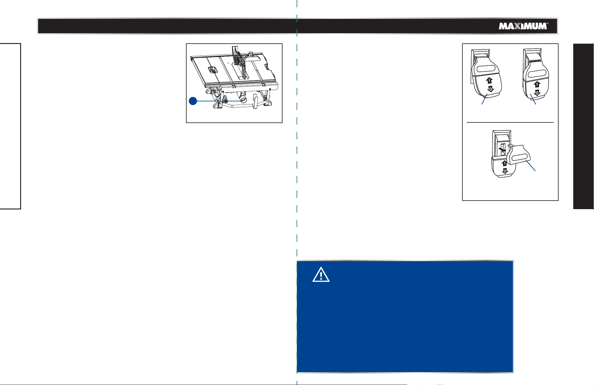
Increase the length of the saw table by using the
sliding table extension.
1
Fig. 31
• Remove the rip fence.
• Unlock the sliding table extension by lifting the
extension table locking lever (1) counter-clockwise.
• Slide the extension table to the desired width.
• Once the extension table is set to the desired width,
relock the lever by pushing the locking lever back
clockwise.
ASSEMBLY
To lock To unlock
1
Fig. 33
NOTE: The rip fence must be secure when the locking handle is
engaged. To increase the grip of the rip fence on the rear lip of the
table, tighten the clamp screw (4) on the rear of the rip fence by
turning it clockwise. (Fig. 30)
NOTE:
• Use the scale on the front rail when a specific width is desired.
• Rapidly set the rip fence to 14” (355.6 mm) on the right rail with
rapid position block (2) (See Fig. 33) and to more easily read the
extended length.
Page 19
model no. 055-6766-2 | contact us 1-888-670-6682
model no. 055-6766-2 | contact us 1-888-670-6682
3736
CONNECT TO A DUST COLLECTION SYSTEM
(Fig. 34)
The dust extraction port (1) with 2.5" (6.35 cm) size
is located on the back of the table saw. This port can
be connected directly to a dust collection system by
connecting the pickup end of the dust collection
hose to the dust port.
ASSEMBLY
BASIC OPERATION OF THE TABLE SAW
The three-prong plug must be plugged into a
matching outlet that is properly installed and
grounded according to all local codes and ordinances.
Improper connection of the equipment can result in
electric shock. Do not modify the plug if it will not fit
the outlet. Have the correct outlet installed by a
1
1
Fig. 34
qualified electrician. Refer to the electrical safety
section in this manual.
POWER SWITCH (Fig. 35)
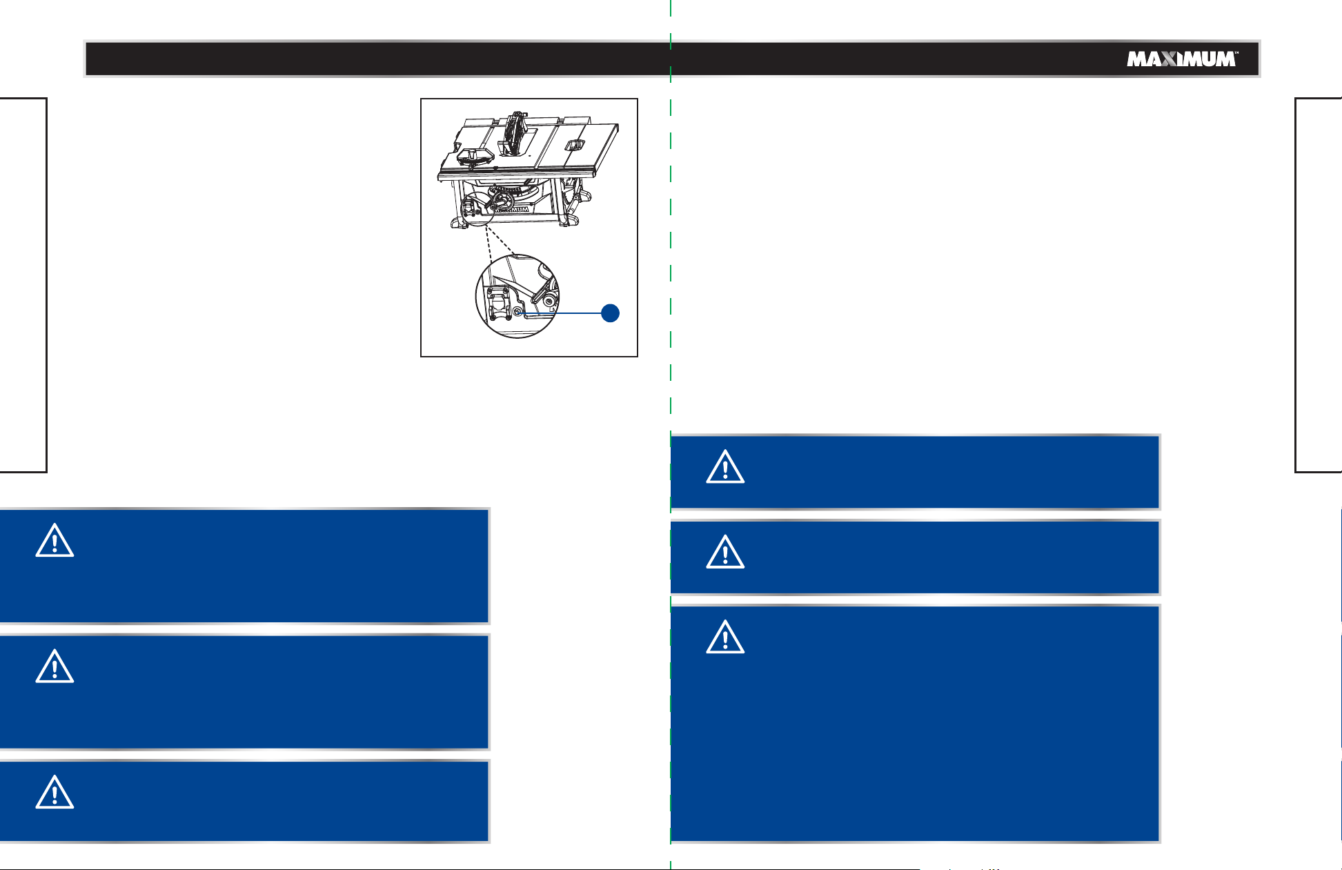
This saw is equipped with a switch assembly that has
a built-in locking feature. This feature is intended to
prevent unauthorized and possible hazardous use by
children and others.
TO TURN YOUR SAW ON:
• With the switch key inserted into the switch, lift the
switch to turn ON ( l ).
TO TURN YOUR SAW OFF:
• Press the switch down to turn OFF ( O ).
PULL OUT TO LOCK
PULL OUT TO LOCK
Switch On Switch Off
PULL OUT TO LOCK
Switch Key
Switch in Locked Position
Fig. 35
OPERATION
WARNING!
• Do not allow familiarity with tools to make you careless.
Remember that a careless fraction of a second is sufficient
to inflict severe injury.
• Always wear eye protection that conforms with CUL
requirements. Failure to do so could result in objects being
thrown into your eyes, resulting in possible serious injury.
• Do not use any attachments or accessories not recommended
by the manufacturer of this tool. The use of attachments or
accessories not recommended can result in serious personal
injury.
• Although many of the illustrations in this manual are shown
with the blade guard removed for clarity, do not operate the
saw without the blade guard unless specifically instructed
to do so.
Page 20
model no. 055-6766-2 | contact us 1-888-670-6682
model no. 055-6766-2 | contact us 1-888-670-6682
3938
TO LOCK YOUR SAW:
• Press the switch down.
• Remove the switch key from the switch and store
in a safe, secure location.
OVERLOAD PROTECTION (Fig. 36)
The saw is equipped with an overload switch (1) to
prevent the saw from overload damage. The saw
will stop if the machine was overloaded with cutting
or low voltage. Turn the switch to the Off position
and allow the motor to cool down for at least five
minutes. Press the overload switch button to
reactivate the overload switch. After the motor has
cooled down, turn the switch to the On position. The
saw should now start.
OPERATION
MAKING CUTS
Before using the table saw, polish the table with an automotive wax in order to keep it
clean and make it easier to slide the workpiece.
There are two basic types of table saw cuts: ripping and crosscutting. In general, ripping
means cutting with the grain, along the length of the workpiece. Crosscutting means
either cutting across the width or across the grain of the workpiece. However, with
man-made materials, this distinction can be difficult to make.
Therefore, cutting a piece of wood to a different width is ripping and cutting across the
short dimension is crosscutting. Neither ripping nor crosscutting operations can be
performed safety freehand: ripping requires the use of the rip fence, and crosscutting
requires the use of the mitre gauge.
1
Fig. 36
OPERATION
WARNING!
Overheating may be caused by misaligned parts or by a dull
blade. Inspect the saw for proper setup before using it again.
WARNING!
• ALWAYS remove the switch key when the tool is not in
use and keep it in a safe place. In the event of a power
failure, turn the switch OFF ( O ) and remove the key. This
action will prevent the tool from accidentally starting when
power returns.
WARNING!
• ALWAYS make sure your workpiece is not in contact with
the blade before operating the switch to start the tool.
Failure to heed this warning may cause the workpiece to
be kicked back toward the operator and result in serious
personal injury.
WARNING!
• To reduce the risk of accidental starting, always make sure
the switch is in the OFF ( O ) position before plugging tool
into the power source.
WARNING!
Do not use blades rated less than the speed of this tool. Failure
to heed this warning could result in personal injury.
CAUTION!
Make sure you read the general safety guidelines for the table
saw before operating it. Your safety depends on it. Verify the
following every time the saw is used:
• The blade is tight.
• The bevel angle locking knob is tight.
• If ripping, the fence locking handle is tight, the fence is parallel
and the mitre gauge locking handle is tight.
• If crosscutting, the mitre gauge knob is tight.
• The blade guard and riving knife are in place and are working
properly.
• Safety glasses are being worn.
Failure to adhere to these safety rules can greatly increase the
chances of injury.
Page 21
model no. 055-6766-2 | contact us 1-888-670-6682
model no. 055-6766-2 | contact us 1-888-670-6682
4140
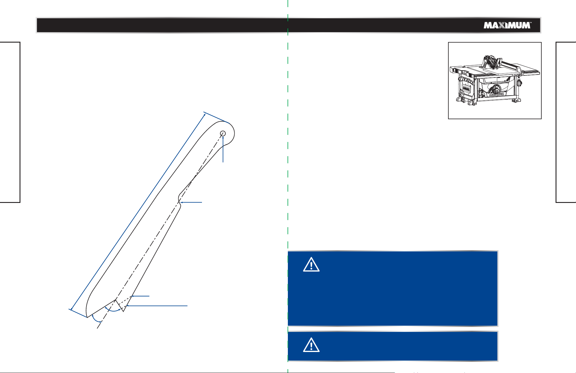
PUSH STICK (Fig. 37)
Push sticks are devices used for safely pushing a workpiece through the blade instead of
using your hands. They can be made from scrap wood in various sizes and shapes to be
used in a specific project. The stick must be narrower than the workpiece, with a 90°
notch in one end and shaped for a grip on the other end.
• Use good quality plywood or solid wood.
• Use 1/2" (1.27 cm) or 3/4" (1.9 cm) material.
• Push stick MUST be thinner than the width
of material being cut.
OPERATION
15 3/4" (40 cm)
Drill hole
for hanging
Notch to
prevent hand
from slipping
RIPPING (Fig. 38)
• Remove the mitre gauge, and secure the rip fence
to table.
• Adjust the blade so that it is approximately 1/8"
(3.2 mm) higher than the workpiece.
• Hold the workpiece flat on the table and against the
fence. Keep the workpiece approximately 1"
(2.5 cm) away from the blade.
• Turn the saw On, and allow the blade to come up to
full speed.
• Slowly feed the workpiece into the blade by pushing
forward only on the section of the workpiece that
will pass between the blade and the fence.
• Keep your thumbs off the table top. When both of
your thumbs touch the front edge of the table,
complete the cut using a push stick.
• The push stick should always be used when the
ripped workpiece is 2" (5 cm) wide or narrower.
• Continue to push the workpiece with the push stick
until it passes the blade guard and clears the rear of
the table.
• Never pull the workpiece back while the blade is
turning. Turn the switch Off. When the blade comes
to a complete stop, raise the anti-kickback pawls on
either side of the riving knife, if necessary, and then
slide the workpiece out.
Fig. 38
OPERATION
20°-30°
90°
Cut here to push
1/2" (1.27 cm) wood
Cut here to push
3/4" (1.9 cm) wood
WARNING!
To prevent serious injury:
• Never use the mitre gauge when ripping.
• Never use more than one rip fence during a single cut.
• Do not allow familiarity with or frequent use of your table saw
to cause careless mistakes. Remember that even a fraction of
a second of carelessness is enough to cause a severe injury.
• Keep both hands away from the blade and path of the blade.
• When ripping, the workpiece must have a straight edge
against the fence, and must not be warped, twisted or bowed.
Fig. 37
CAUTION!
Avoid kickback by pushing only on the section of workpiece
that will pass between the blade and the fence.
Page 22
model no. 055-6766-2 | contact us 1-888-670-6682
model no. 055-6766-2 | contact us 1-888-670-6682
4342
BEVEL RIPPING
This operation is the same as ripping, except that the
bevel angle is set to an angle other than 0°.
Make sure that you only cut with the workpiece and
the fence on the right-hand side of the blade.
RIPPING SMALL PIECES (Fig. 39)
• It is not safe to rip small pieces. It is not safe to put
your hands close to the blade. In order to ensure
your safety, rip the small piece from a larger piece.
• When a small width is to be ripped and your hand
cannot be safely put between the blade and the rip
fence, use one or more push sticks. Use the push
stick to hold the workpiece against the table top
and the fence, and to push the workpiece
completely past the blade.
Avoid injury resulting from contact with the blade.
Never make through-cuts narrower than 3/4"
(1.9 cm) wide.
OPERATION
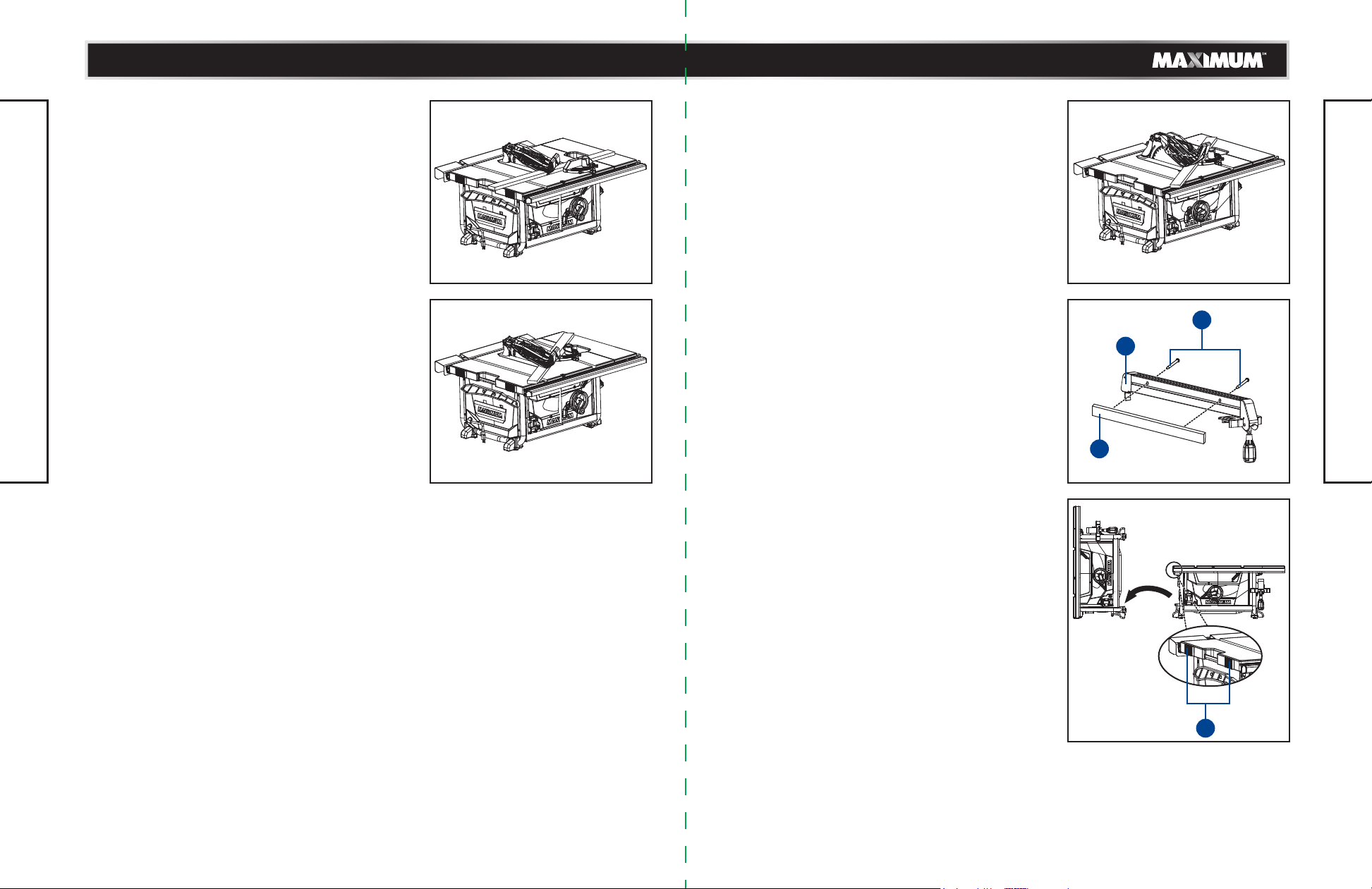
CROSSCUTTING (Fig. 40)
• Remove the rip fence, and place the mitre gauge in
one of the mitre gauge grooves on the table.
• Adjust the blade height so that it is 1/8" (3.2 mm)
higher than the top of the workpiece.
• Hold the workpiece firmly against the mitre gauge,
with the blade path in line with the desired cut
location. Move the workpiece to within 1" (2.5 cm)
of the blade.
• Start the saw, and wait for the blade to come up to
Fig. 39 Fig. 40
full speed. Never stand directly in line with the path
of the saw blade.
• Keep the workpiece against the face of the mitre
gauge and flat against the table. Slowly push the
workpiece through the blade.
• Do not attempt to pull the workpiece backward
while the blade is turning. Turn the switch off, and
wait until the blade has come to a complete stop
before carefully sliding the workpiece out.
OPERATION
CAUTION!
To prevent serious injury:
• Do not allow familiarity with or frequent use of your table saw
to cause careless mistakes. Remember that even a fraction of
a second of carelessness is enough to cause a severe injury.
• Keep both hands away from the blade and the path of the
blade.
• Never attempt to pull the workpiece backward during a cutting
operation. This will cause kickback, and serious injury to the
user can occur.
WARNING!
In order to avoid instability, always place the larger surface of
the workpiece on the table when crosscutting and/or bevel
crosscutting.
Page 23
model no. 055-6766-2 | contact us 1-888-670-6682
model no. 055-6766-2 | contact us 1-888-670-6682
4544
BEVEL CROSSCUTTING 0-45° BLADE BEVEL
AND 90° MITRE ANGLE (Fig. 41)
This cutting operation is the same as crosscutting,
except that the blade is at a bevel angle other than
0°.
This operation must be performed with mitre gauge
in the right side groove.
• Adjust the blade to the desired angle, and then
tighten the blade bevel-locking lever.
• Tighten the mitre lock handle at 90°.
• Hold the workpiece firmly against the face of the
mitre gauge throughout the cutting operation.
Make sure that you always work to the right side
of the blade during this type of cut. The mitre gauge
must be in the right side groove, because the bevel
angle may cause the blade guard to interfere with
the cut if it is used in the left side groove.
0-45° BLADE BEVEL AND 0-45° MITRE ANGLE
OPERATION
(Fig. 42)
This sawing operation combines a mitre angle with
a bevel angle. This operation must be performed
with the mitre gauge in the right side groove.
• Set the mitre gauge to the desired angle.
• Place the mitre gauge in the right side groove of
the table.
• Set the blade bevel to the desired bevel angle, and
tighten the blade bevel-locking lever.
• Hold the workpiece firmly against the face of the
mitre gauge throughout the cutting operation.
Make sure that you always work to the right side of
the blade during this type of cut. The mitre gauge
must be in the right side groove, because the bevel
angle may cause the blade guard to interfere with
the cut if it is used in the left side groove.
Fig. 41
Fig. 42
MITRING 0-45° MITRE ANGLE (Fig. 43)
This sawing operation is the same as crosscutting,
except that the mitre gauge is locked at an angle
other than 90°.
• Set the blade to the 0° bevel angle, and then
tighten the blade bevel locking lever.
• Set the mitre gauge to the desired mitre angle, and
lock it in position by tightening the mitre gauge
locking handle.
• Hold the workpiece firmly against the face of the
mitre gauge throughout the cutting operation.
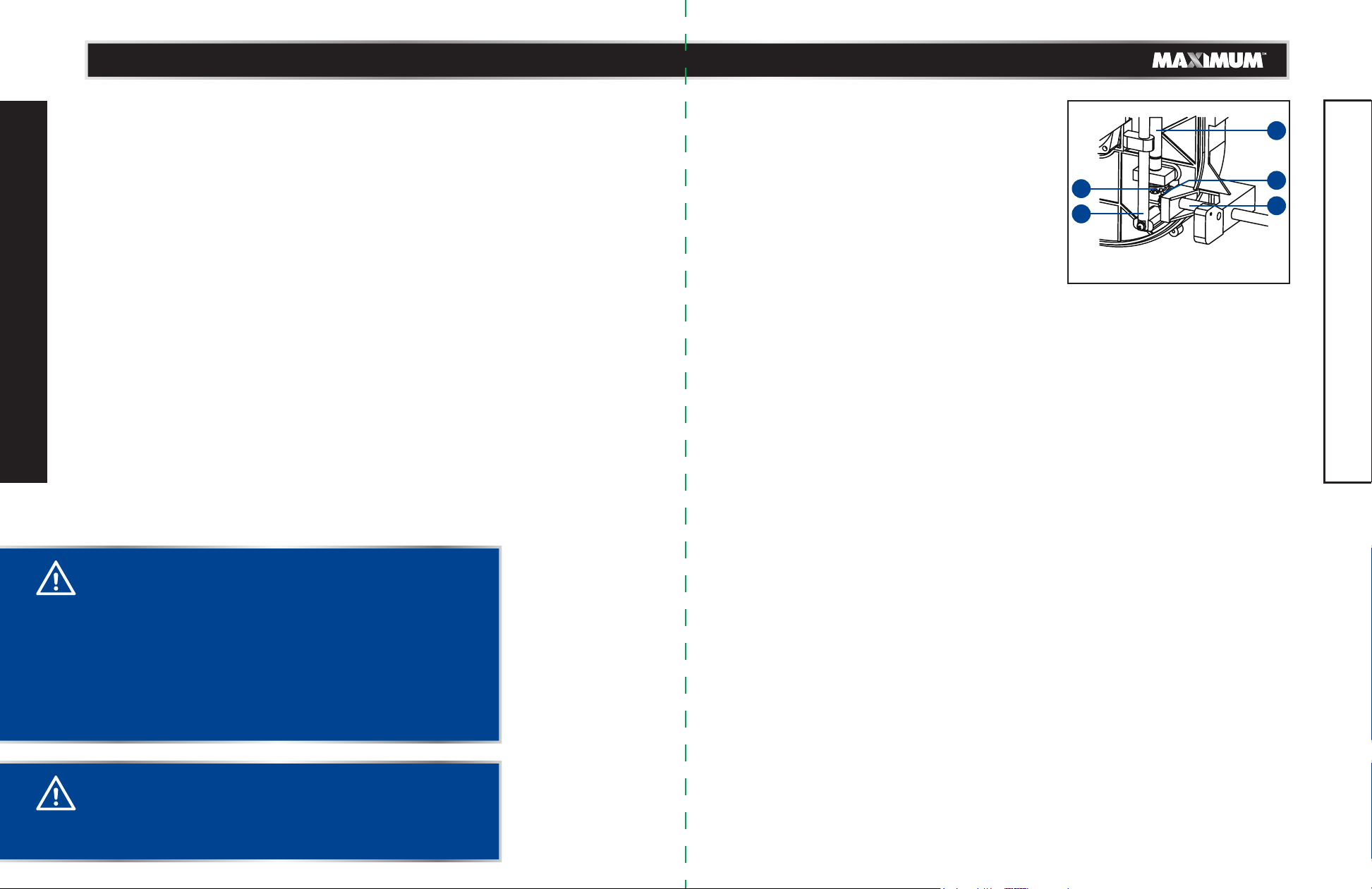
USING WOOD FACING ON THE RIP FENCE
(Fig. 44)
When performing certain special cutting operations,
add a wood facing to either side of the rip fence.
• Use a smooth, straight, 3/4" (1.9 cm) thick wooden
facing (1) that is as long as the rip fence.
• Attach the wood facing (1) to the rip fence (2) using
wood screws (3) (not included) through the drilled
hole previously in the fence. A wood facing should
be used when ripping material such as thin paneling,
in order to prevent the material from catching
between the bottom of the fence and the table.
TO STORE THE TABLE SAW VERTICALLY
(Fig. 45)
The table saw can be stored vertically with the left
side of saw on the level surface to occupy a narrower
space when not in use. The rubber mat (1) can better
protect the left side of the work table with its rubber
feet.
Make sure that
rip fence, anti-kickback pawls, mitre gauge, etc.)
securely before storing the table saw.
you store all the accessories (such as
Fig. 43
3
2
1
Fig. 44
OPERATION
1
Fig. 45
Page 24
model no. 055-6766-2 | contact us 1-888-670-6682
model no. 055-6766-2 | contact us 1-888-670-6682
4746
GENERAL MAINTENANCE
Avoid using slovents when cleaning plastic parts. Most plastics are susceptible to damage
from various types of commercial solvents and may be damaged by their use. Use clean
cloths to remove dirt, dust, oil, grease, etc.
• Periodically check all clamps, nuts, bolts and screws for tightness and condition. Make
sure the table insert is in good condition and in position.
• Check the blade guard assembly.
• To maintain the table surfaces, fence and rails, periodically apply paste wax to them and
buff them to provide smooth functioning.
• Protect the blade by cleaning out sawdust from underneath the table and in the blade
teeth. Use a resin solvent on the blade teeth.
• Clean plastic parts only with a soft, damp cloth. DO NOT use any aerosol or petroleum
solvents.
LUBRICATION
All of the bearings in this tool are lubricated with a sufficient amout of high-grade
lubricant for the life of the unit under normal operating conditions. Therefore, no further
lubrication is required.
MAINTENANCE
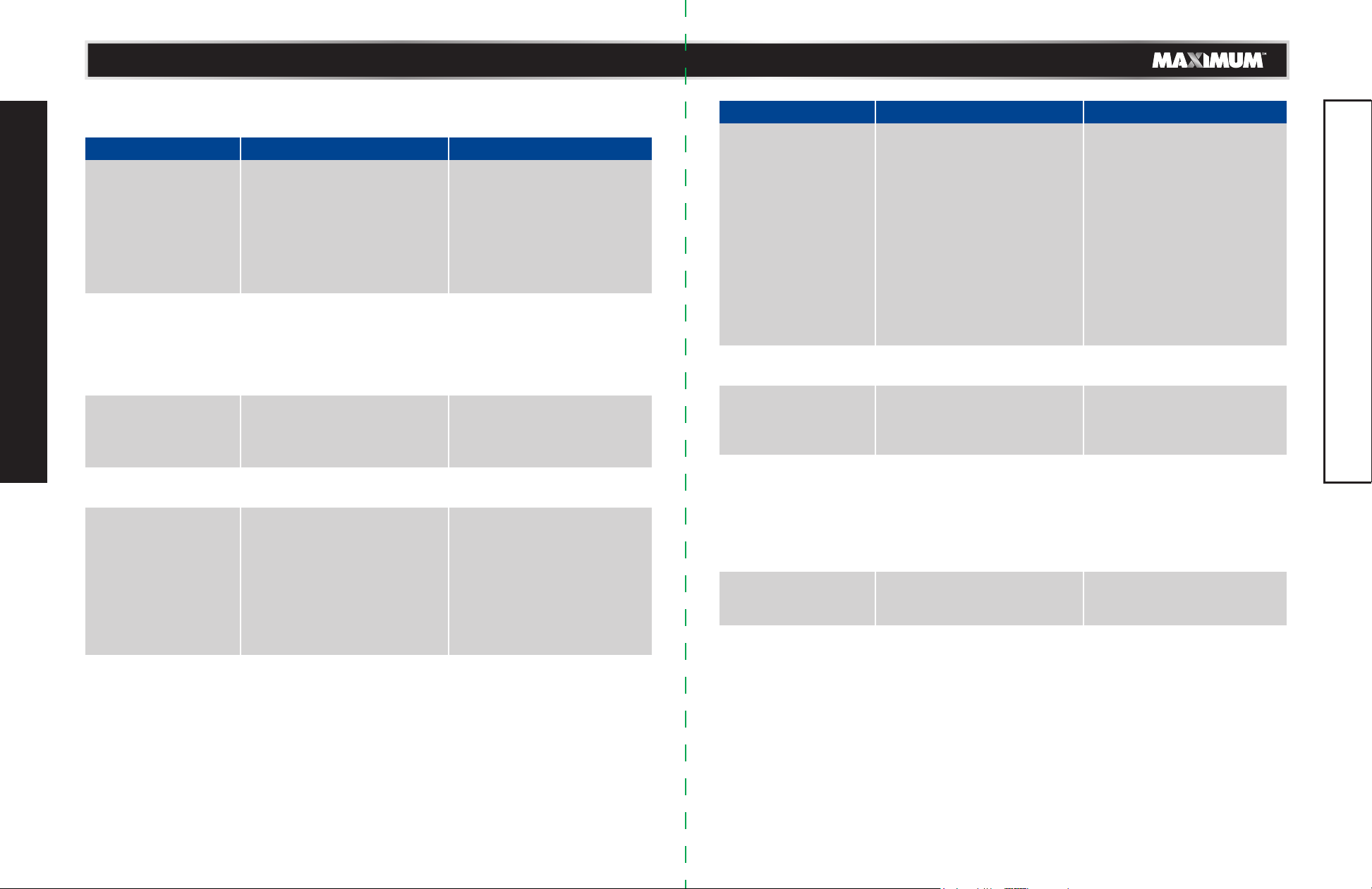
BLADE RAISING AND TILTING MECHANISM
(Fig. 46)
Check the blade raising and tilting mechanism for
looseness, binding, or other abnormalities after
every five hours of operation.
• Unplug the table saw from the power supply outlet
and turn it upside down.
• Turn the screw shaft (1), which connects with the
bevel gear (2), in clockwise or counter-clockwise
direction.
• This turning movement will be transferred to the
vertical guiding rod (3) through the taper gear (4)
and transverse shaft (5), thereby causing the
vertical guiding rod to move up and down.
4
4
3
2
1
Fig. 46
MAINTENANCE
WARNING!
• When servicing, use only identical replacement parts. Use
of any other parts may create a hazard or cause product
damage.
• For your own safety, turn the switch Off and remove the
key. Remove the plug from the power source before
performing maintenance on or lubricating your saw.
• Before performing any maintenance, make sure the tool
is unplugged from the power supply and the switch is in
the Off (O) position. Failure to heed this warning could
result in serious personal injury.
WARNING!
Do not at any time let brake fluids, gasoline, petroleumbased products, penetrating oils, etc., come in contact
with plastic parts. Chemicals can damage, weaken or
destory plastic, which may result in serious personal injury.
Page 25
model no. 055-6766-2 | contact us 1-888-670-6682
model no. 055-6766-2 | contact us 1-888-670-6682
4948
TROUBLESHOOTING
PROBLEM Possible Causes Solution
Saw will not start. • Overload tripped.
• Saw is not plugged in.
• Fuse blown or circuit breaker
tripped.
• Cord is damaged.
Does not make 45° and
90° rip cuts.
Material pinches blade
when ripping.
TROUBLESHOOTING
Material binds on riving
knife.
Saw makes
unsatisfactory cuts.
• Positive stop not adjusted
correctly.
• Bevel angle pointer not set
accurately.
• Rip fence not properly
aligned.
• Rip fence not aligned with
blade.
• Warped wood, edge against
fence is not straight.
• Riving knife not aligned
correctly with blade.
• Dull blade.
• Blade mounted backwards.
• Gum or pitch on blade.
• Incorrect blade for work
being done.
• Gum or pitch on blade
causing erratic feed.
• Allow motor to cool and
reset by pushing reset
switch.
• Plug in saw.
• Replace fuse or reset circuit
breaker.
• Have the cord replaced by a
qualified electrician.
• Check blade with square and
adjust positive stop.
• Check blade with square and
adjust to zero.
• Align the rip fence with the
mitre gauge slot.
• Check and adjust rip fence.
• Select another piece of
wood.
• Check and align riving knife
with blade.
• Replace blade.
• Turn the blade around.
• Remove the blade and clean
with turpentine and coarse
steel wool.
• Change the blade.
• Clean table with turpentine
and steel wool.
PROBLEM Possible Causes Solution
Material kicked back
from blade.
Blade does not raise or
tilt freely.
Blade does not come
up to speed or reset
trips too easily.
Machine vibrates
excessively.
Does not make
accurate 45° and 90°
cuts.
• Rip fence out of adjustment.
• Riving knife not aligned with
blade.
• Feeding stock without rip
fence.
• Riving knife not in place.
• Dull blade.
• The operator letting go of
material before it is past saw
blade.
• Mitre angle lock knob is not
tight.
• Sawdust and dirt in elevation/
tilting mechanisms.
• Extension cord too light or
too long.
• Low house voltage.
• The saw is not mounted
securely to the stand.
• Stand is on uneven floor.
• Workbench is moving.
• Damaged saw blade.
• Mitre gauge out of
adjustment.
• Align rip fence with mitre
gauge slot.
• Align riving knife with blade.
• Install and use rip fence.
• Install and use riving knife
(with guard).
• Replace blade.
• Push material all the way
past saw blade before
releasing work.
• Tighten knob.
• Brush or blow out loose dust
and dirt.
• Replace with adequate size
cord.
• Contact your electric
company.
• Tighten all mounting
hardware.
• Reposition on flat, level
surface.
• Securely the workbench to
floor.
• Replace blade.
• Adjust mitre gauge.
TROUBLESHOOTING
Page 26
model no. 055-6766-2 | contact us 1-888-670-6682
model no. 055-6766-2 | contact us 1-888-670-6682
5150
16
17
15
EXPLODED VIEW
17
17
14
14
24
26
23
27
18
28
25
29
30
31
32
40
37
38
39
22
21
208
36
6
7
19
20
6
4
5
12
13
11
201
35
34
7
34
2
3
10
9
35
33
33
1
61
60
59
56
545351504948
41
42
43
44
100
45
46
47
86
87
101
103
104
105
8
84
216
6
88
102
52
55
72
80
79
82 81
210
102
107
89
90
34
35
91
21334
7778
209
57
108
58
73
94
6869
70
71
74
7576
83
84
6
85
92
84
19
211
106
7
6
7
93
34
35
95
109
210
211
212
213
62
34
6667
99
6
84
7
64
63
65
EXPLODED VIEW
199
96
97
98
Page 27
model no. 055-6766-2 | contact us 1-888-670-6682
model no. 055-6766-2 | contact us 1-888-670-6682
5352
198 224
150
112
111
149
148
111
7
145
204
EXPLODED VIEW
203
142 141 140112111
6217
144
143
160
135
6
84
7
133
6
84
7
147
202
146
134
111
112
84
163
158
178
205
160
162
164
165
166
167
161
175
157
207
161206
176
194
111
217
177
156
160
193
218
219
156
220
192
155
195
170 171169168
179
223
191
180
84
222
221
6
154152
111 200
17
182
181
183
184
186
159
34
35
174
172
185
189
115 114
212
6 131
217
7
130
129
126
112
111
125
124
123
127
132
128
121
122
130
120
116
119
197
214
117118
196
94
215
139
138
135
137
136
6
7
187
151152
EXPLODED VIEW
173
186
188
190
Page 28
model no. 055-6766-2 | contact us 1-888-670-6682
model no. 055-6766-2 | contact us 1-888-670-6682
5554
PARTS LIST
No.
Description
1
Mitre gauge Handle
2
Large gasket Ø6
3
Mitre gauge
4
Pin
5
Sliding bar
6
Washer Ø4
7
Bolt M4 x 8
8
Bolt M4 x 20
9
Nut M4
10
Pointer (A)
11
Orientation board
12
Bolt M5 x 8
13
PARTS LIST
Orientation board fix base
14
Bolt M10
15
Rear out-feed support
16
Rear out-feed support pole
17
Bolt M4 x 10
18
Split washer Ø12
19
Locking nut M6
20
Spring
21
Rear fix base for rip fence
22
Rip pipe wheel
23
Round pin 4 x 39
24
Bolt (C)
25
Rear lockplate
26
Bolt M4 x 4
27
Spring piece
28
Locking board
29
Rub washer
30
Wobbler wheel
31
Nut M8
Qty
1
1
1
1
1
25
25
3
3
1
1
2
1
2
1
2
10
2
5
1
1
1
1
1
1
2
1
1
1
1
3
No.
Description
32
Handle
33
Bolt M6 x 20
34
Washer Ø6
35
Spring washer Ø6
36
Pointer
37
Holder
38
Blot 5 x 12
39
Spring round pin 8 x40
40
Spring round pin 5 x40
41
Plate (a)
42
Plate (b)
43
Table insert
44
Spring
45
Card board
46
Rear press board
47
Bolt M4 x 6
48
Split washer Ø14
49
Kickback pawl plate (b)
50
Spring round pin 4 x 16
51
Latch spring
52
Support base
53
Bolt M3 x 10
54
Torsional spring
55
Kickback pawl plate (A)
56
Split washer Ø14
57
Pin
58
Knob
59
Left blade guard
60
Blade guard support base
61
Bolt M5 x 16
62
Right blade guard
Qty
1
3
24
34
1
1
1
1
1
1
1
1
1
1
1
1
1
1
1
1
1
1
1
1
1
1
1
1
1
1
1
No.
Description
63
Guard spring
64
Guard screw M5 x 10
65
Pin cap
66
Split washer Ø5
67
Sliding pin
68
Stop pin
69
Spring
70
Locking knob
71
Riving knife press board
72
Riving knife
73
Position axes
74
Riving knife orientation pin
75
Riving knife fix base
76
Split washer Ø3.5
77
Locking nut M3
78
Adjustment pole
79
Bolt M3 x 18
80
Support plate ring
81
Bolt M5 x 10
82
Bolt M6 x 20
83
Bolt M4 x 8
84
Spring washer Ø4
85
Worktable pointer
86
Sunk head screw M4 x 12
87
Foot pad
88
Main worktable
89
Slip sheet
90
Fix base (b)
91
Bolt M6 x 16
92
Stop block
93
Fix base (a)
94
Gap piece
Qty
2
4
2
2
1
1
2
1
1
1
2
1
1
1
1
1
1
1
4
2
1
30
1
8
2
1
2
2
4
1
1
2
No.
Description
95
Screw M6 x 16
96
Hinge
97
Protection spring
98
Bolt M6 x 130
99
Protection board
100
Restoration spring
101
Mandrel
102
Nut M8
103
Spring pocket
104
Tension spring
105
Locking rod
106
Lengthen nut (b) M8
107
Locking knob
108
Tension piece
109
Locking block
110
Limitation plate (a)
111
Washer Ø5
112
Spring washer Ø5
113
Bolt M5 x 14
114
Slip sheet (b)
115
Fixed rear scale bar
116
Active rear scale bar
117
Rip fence fix block
118
Insert
119
Label
120
Extension table
121
Active main scale base
122
Insert (a)
123
Bolt M5 x 20
124
Stop block
125
Fix block
126
Screw M6 x 18
Qty
2
1
1
1
1
1
1
20
1
1
1
1
1
1
1
1
30
30
6
2
1
1
1
1
1
1
1
1
3
1
1
4
PARTS LIST
Page 29
model no. 055-6766-2 | contact us 1-888-670-6682
model no. 055-6766-2 | contact us 1-888-670-6682
5756
Description
No.
Bolt M4.2 x 14
127
Stop block
128
Insert (b)
129
Slip sheet (a)
130
Fixation main scale bar
131
Insert
132
Baffle
133
Butterfly screw M5 x 12
134
Baffle
135
Nut M16
136
Blade outer plywood
137
Blade inner plywood
138
Machine body
139
Bolt M5 x 20
PARTS LIST
140
Flat key 4 x 8
141
Adjustment pole (a)
142
Bevel gear
143
Circlip for shaft Ø10
144
Adjustment base
145
Adjustment pole (b)
146
Cover
147
Bolt M4 x 12
148
Trunnion
149
Bolt M5 x 20
150
Butterfly nut M8
151
Blade wrench
152
Blade
153
Support base
154
Bolt ST4.2 x 30
155
Bolt M5 x 35
156
Right panel
157
Screw M8 x 30
158
Qty
1
1
1
2
1
1
1
1
1
1
1
1
1
2
2
1
2
2
1
1
1
2
2
8
1
2
1
1
4
2
1
1
Description
No.
Frame groupware
159
Locking nut M5
160
Bolt ST4.2 x 10
161
Push stick block
162
Left panel
163
Push stick
164
Wire-wrap board
165
Wire outlet
166
Supply cord
167
Left foot
168
Rubber pad
169
Right foot
170
Bolt ST4.2 x 19
171
Front foot
172
Back foot
173
Bolt M6 x 16
174
Reinforce panel
175
Angle adjustment base
176
Bolt M5 x 16
177
Front panel
178
Rotation label
179
Angle pointer
180
Ring
181
Locking compression spring
182
Pole screw
183
Nut M5
184
Locking handle
185
Bolt M5 x 12
186
Rotation wheel
187
Rotation handle
188
Knob
189
Bolt
190
Qty
1
5
4
2
1
1
1
1
1
2
4
2
12
2
2
4
1
1
3
1
1
1
1
1
1
1
1
1
1
1
1
1
No.
Description
191
Bolt ST4.2 x 18
192
Switch
193
Switch board
194
Overload protection
195
Bolt M5 x 20
196
Switch box cover
197
Bolt ST4.8 x 50
198
Body pretection
199
Knob
200
Bolt ST4.2 x 9.5
201
Rip fence
202
Dust extraction port
203
Lower apron
204
Bolt M4 x 10
205
Crimping pin
206
Clamp
207
Bolt ST4.2 x 10
Qty
4
1
1
1
2
1
3
1
1
2
1
1
1
1
1
1
3
No.
Description
208
Pole
209
Limitation plate (a)
210
Limitation plate (b)
211
Plastic bolt
212
Bolt M5 x 30
213
Spring
214
Strain relief
215
Bolt M6 x 12
216
Platen
217
Blade storage (a)
218
Blade storage (b)
219
Fixing plate
220
Anti-kickback pawls storage
221
Accessory storage
222
Fixing plate
223
Horizontal support
224
Motor
Qty
1
1
1
1
1
1
2
1
1
1
1
1
1
1
1
1
1
PARTS LIST
Page 30
58
model no. 055-6766-2 | contact us 1-888-670-6682
model no. 055-6766-2 | contact us 1-888-670-6682
59
5-Year Limited Warranty
This MAXIMUM product is guaranteed for a period of 5
years from the date of original retail purchase against
defects in workmanship and materials only and is
subject to the following components:
a) Component A: The carrying case is guaranteed for a
period of 1-year from the date of original retail
purchase against defects in workmanship and
materials.
b) Component B: Accessories, including drill bits and
saw blades, do not carry a warranty.
Subject to the conditions and limitations described
below, this product, if returned to us with proof of
purchase within the stated warranty period and if
covered under this warranty, will be repaired or replaced
(with the same model, or one of equal value or specification), at
the sole discretion of the Maximum Canada authorised repair centre
(“Service Provider”). We will bear the cost of any repair or replacement and any costs of
labour relating thereto.
WARRANTY
These warranties are subject to the following conditions and limitations:*
a) a bill of sale verifying the purchase and purchase date must be provided;
b) defects in workmanship and material to be assessed and determined by the Service
Provider;
c) this warranty will not apply to any product or part thereof which is worn or broken or
which has become inoperative due to abuse, misuse, accidental damage, neglect or
lack of proper installation, operation or maintenance (as outlined in the applicable
owner’s manual or operating instructions);
d) this warranty does not apply to normal wear and tear or to expendable parts or
accessories (including drill bits and saw blades) that may be supplied with the
product that by their nature have a limited life span and are expected to become
inoperative or unusable after a reasonable period of use;
e) this warranty will not apply to routine maintenance and consumable items such as,
but not limited to, fuel, lubricants, vacuum bags, blades, belts, sandpaper, bits, fluids,
rubber o-rings, tune-ups or adjustments;
f) this warranty excludes the following components that may accompany your product:
(1) The carrying case, which is only for a period of 1-year from the date of original
retail purchase against defects in workmanship and materials.
(2) Accessories, including drill bits and saw blades, which do not carry a warranty of
any kind.
g) this warranty will not apply where damage is caused by repairs made or attempted
by others (i.e. persons not authorized by the manufacturer), and any such
unauthorized repairs or attempted repairs shall void this warranty in its entirety;
h) this warranty will not apply to any parts other than original parts, except to the
90
SATISFACTION
GUARANTEE
YEAR
AN
1
REPAIR
WARRANTY
DE GARANTIE
SUR RÉPARATIONS
DAYS
JOURS
DE SATISFACTION
GARANTIE
5
WARRANTY
DE GARANTIE
LIMITED
LIMITÉE
YEAR
ANS
extent that the retailer or manufacturer or persons authorized by either of them have
repaired or replaced them;
i) this warranty will not apply to any product that was sold to the original purchaser as
a reconditioned or refurbished product (unless otherwise specified in writing);
j) this warranty will not apply to any product or part thereof if any part from another
manufacturer is installed therein or any repairs or alterations have been made or
attempted by unauthorized persons;
k) this warranty will not apply to normal deterioration of the exterior finish, such as, but
not limited to, scratches, dents, paint chips, or to any corrosion or discolouring by
heat, abrasive and chemical cleaners;
l) this warranty will not apply to component parts sold by and identified as the product
of another company, which shall be covered under that product manufacturer’s
warranty, if any;
m) any products replaced by the retailer in attempt to fulfill warranty obligations is
subject to the original product warranty conditions and related time period as
initiated by the original date of purchase; if product is purchased in Quebec, the
warranty term will be extended for a period equal to the time during which the
Quebec retailer possesses the product in attempt to fulfill warranty obligations;
replaced product will not default to new product warranty conditions; and
n) The retailer and manufacturer’s sole obligation and the purchaser’s sole remedy
under this warranty shall be as set out herein. The warranties contained herein are not
transferable and are given only to the purchaser. FURTHER, THE WARRANTIES SET
OUT HEREIN ARE IN LIEU OF ALL OTHER WARRANTIES OR CONDITIONS,
WHETHER EXPRESS, IMPLIED OR STATUTORY (INCLUDING SUCH AS ARISE UNDER
THE SALE OF GOODS ACT OR THE INTERNATIONAL SALE OF GOODS ACT),
ARISING OUT OF A COURSE OF DEALING OR USAGE OF TRADE OR OTHERWISE,
INCLUDING, SUBJECT TO APPLICABLE LAW, ANY IMPLIED WARRANTIES OR
CONDITIONS OF MERCHANTABILITY, MERCHANTABLE QUALITY, FITNESS OR
ADEQUACY FOR A PARTICULAR PURPOSE OR USE, AND ALL OTHER SUCH
WARRANTIES ARE EXPRESSLY DISCLAIMED BY THE RETAILER AND
MANUFACTURER.
Additional Limitations
This warranty applies only to the original purchaser and may not be transferred.
This warranty applies for a period of 5 years from the date of original retail purchase, as
indicated on the bill of sale.
Neither the retailer, Maximum Canada, nor the manufacturer shall be liable for any other
expense, loss or damage, including, without limitation, any indirect, incidental,
consequential or exemplary damages arising in connection with the sale, use or inability
to use this product.
Under no circumstances shall the retailer, Maximum Canada, or manufacturer be liable to
the purchaser for any claim for (a) indirect, special, punitive, incidental, exemplary, or
consequential damages, (b) compensation for loss of profits, anticipated revenue,
savings or goodwill, or other economic loss of the purchaser, (c) exemplary, aggravated
or punitive damages howsoever incurred, (d) contribution or set-off in respect of any
WARRANTY
Page 31
model no. 055-6766-2 | contact us 1-888-670-6682model no. 055-6766-2 | contact us 1-888-670-6682
60
claims against the purchaser, (e) any damages whatsoever relating to third party
products or services or the purchaser’s materials, or (f) any damages whatsoever
relating to interruption, delays, errors or omissions; in each case under any theory of law
or equity, arising out of or in any way related to this warranty, even if advised of the
possibility thereof. Notwithstanding any provision herein or entitlement of the purchaser
at law, in equity or otherwise, in no event shall the liability of the retailer or
manufacturer under this warranty, whether in contract, tort, product liability or
otherwise, exceed, in the aggregate, the amount paid by the purchaser to the retailer for
the product to which this warranty applies.
*Notice to Consumer
This warranty gives you specific legal rights, and you may have other rights, which may
vary from province to province. The provisions contained in this warranty are not
intended to limit, modify, take away from, disclaim or exclude any statutory warranties
set forth in any applicable provincial or federal legislation.
In addition to the 5-Year Limited Warranty, this MAXIMUM product is covered by our:
1-Year Repair Warranty
Maximum Canada will maintain this product and replace critical parts which have worn
beyond reasonable use through normal use of such product, any time during the first
year after purchase.
WARRANTY
The following are excluded from this 1-Year Repair Warranty:
a) Missing or damaged parts or components that are a result of abuse or misuse;
b) Any wear and tear to non-critical parts or accessories that do not affect the core
function of the product.
90-Day Satisfaction Guarantee
If you are not completely satisfied with the performance of your MAXIMUM product for
any reason, you can return it within 90 days from the date of purchase with proof of
purchase for exchange or a full refund.
Made in China
Imported by MAXIMUM Canada Toronto, Canada M4S 2B8
 Loading...