

Page 1

Page 2

Page 3
TABLE OF CONTENTS
TECHNICAL SPECIFICATIONS 4
TM
3
GENERAL POWER TOOL SAFETY WARNINGS
SAFETY INSTRUCTIONS FOR ALL SAWS
SYMBOLS 10
PARTS LIST 11
ACCESSORIES 12
KNOW YOUR CIRCULAR SAW 13
OPERATING INSTRUCTIONS 15
WORKING HINTS FOR YOUR CIRCULAR SAW
MAINTENANCE 19
WARRANTY 20
5
8
18
TABLE OF CONTENTS
NOTE: If any parts are missing or damaged, or if you have any
questions, please call our toll-free helpline at 1-888-670-6682
SAVE THESE INSTRUCTIONS
This manual contains important safety and
operating instructions. Read all instructions and
follow them with use of this product.
Page 4

4
model no. 054-8364-8 | contact us 1-888-670-6682
TECHNICAL SPECIFICATIONS
VOLTAGE 120 V 60 Hz AC
CURRENT 15A
SINGLE SPEED 5000 RPM
BLADE
CUTTING CAPACITY
CUTTING DEPTH AT 90°
CUTTING DEPTH AT 45°
BEVEL CAPACITY 0-56°
ARBOUR SIZE
POWER CORD
WEIGHT 11 lb 15 oz (5.41kg)
7 1/4” (18.4 cm) 24-tooth carbide-
2 7/16” (6.2 cm)
1 7/8” (4.8 cm)
5/8” (1.6 cm)
10’ (3 m)
TECHNICAL SPECIFICATIONS
tipped
Page 5
WORK AREA SAFETY
• Keep work area clean and well lit. Cluttered or dark areas invite
accidents.
• Do not operate power tools in explosive atmospheres, such as in the
presence of flammable liquids, gases or dust. Power tools create sparks
which may ignite the dust or fumes.
• Keep children and bystanders away while operating a power tool.
Distractions can cause you to lose control.
WARNING!
Some dust created by power sanding, sawing, grinding,
drilling and other construction activities contains chemicals
known to the state of California to cause cancer, birth
defects or other reproductive harm. Some examples of
these chemicals are:
• Lead from lead-based paints,
• Crystalline silica from bricks and cement and other
masonry products,
• Arsenic and chromium from chemically-treated lumber.
Your risk from these exposures varies, depending on how
often you do this type of work. To reduce your exposure
to these chemicals, work in a well ventilated area, and
work with approved safety equipment, such as those dust
masks that are specially designed to filter out microscopic
particles.
TM
5
GENERAL POWER TOOL SAFETY WARNINGS
WARNING!
This product may contain lead, phthalates or other
chemicals known to the state of california to cause cancer,
birth defects and other reproductive harm. Please wash
your hands after use.
WARNING!
Read all safety warnings and instructions. Failure to follow
the warnings and instructions may result in electric shock,
fire and/or serious injury.
Save all warnings and instructions for future reference.
• The term power tool in the warnings refers to your
electric (corded) power tool or battery-operated
(cordless) power tool.
Page 6
6
model no. 054-8364-8 | contact us 1-888-670-6682
ELECTRICAL SAFETY
• Power tool plugs must match the outlet. Never modify the plug in
• Avoid body contact with grounded surfaces such as pipes, radiators,
• Do not expose power tools to rain or wet conditions. Water entering a
• Do not abuse the cord. Never use the cord for carrying, pulling or
• When operating a power tool outdoors, use an extension cord suitable
• If operating a power tool in a damp location is unavoidable, use a
PERSONAL SAFETY
• Stay alert, watch what you are doing and use common sense when
GENERAL POWER TOOL SAFETY WARNINGS
• Use personal protective equipment. Always wear eye protection.
• Prevent unintentional starting. Ensure the switch is in the off-position
• Remove any adjusting key or wrench before turning the power tool on.
• Do not overreach. Keep proper footing and balance at all times. This
• Dress properly. Do not wear loose clothing or jewellery. Keep your hair,
• If devices are provided for the connection of dust extraction and
any way. Do not use any adapter plugs with grounded power tools.
Unmodified plugs and matching outlets will reduce risk of electric
shock.
ranges and refrigerators. There is an increased risk of electric shock if
your body is grounded.
power tool will increase the risk of electric shock.
unplugging the power tool. Keep cord away from heat, oil, sharp edges
or moving parts. Damaged or entangled cords increase the risk of
electric shock.
for outdoor use. Use of a cord suitable for outdoor use reduces the risk
of electric shock.
residual current device (RCD) protected supply. Use of an RCD reduces
the risk of electric shock.
operating a power tool. Do not use a power tool while you are tired
or under the influence of drugs, alcohol or medication. A moment of
inattention while operating power tools may result in serious personal
injury.
Protective equipment such as dust mask, non-skid safety shoes, hard
hat, or hearing protection used for appropriate conditions will reduce
personal injuries.
before connecting to power source and/or battery pack, picking up or
carrying the tool. Carrying power tools with your finger on the switch
or energizing power tools that have the switch on invites accidents.
A wrench or a key left attached to a rotating part of the power tool may
result in personal injury.
enables better control of the power tool in unexpected situations.
clothing and gloves away from moving parts. Loose clothes, jewellery
or long hair can be caught in moving parts.
collection facilities, ensure these are connected and properly used. Use
of dust collection can reduce dust-related hazards.
Page 7
TM
POWER TOOL USE AND CARE
• Do not force the power tool. Use the correct power tool for your
application. The correct power tool will do the job better and safer at
the rate for which it was designed.
• Do not use the power tool if the switch does not turn it on and off. Any
power tool that cannot be controlled with the switch is dangerous and
must be repaired.
• Disconnect the plug from the power source and/or the battery pack
from the power tool before making any adjustments, changing
accessories, or storing power tools. Such preventive safety measures
reduce the risk of starting the power tool accidentally.
• Store idle power tools out of the reach of children and do not allow
persons unfamiliar with the power tool or these instructions to operate
the power tool.Power tools are dangerous in the hands of untrained
users.
• Maintain power tools. Check for misalignment or binding of moving
parts, breakage of parts and any other condition that may affect the
power tool’s operation. If damaged, have the power tool repaired
before use. Many accidents are caused by poorly maintained power
tools.
• Keep cutting tools sharp and clean. Properly maintained cutting
tools with sharp cutting edges are less likely to bind and are easier to
control.
• Use the power tool, accessories and tool bits etc., in accordance with
these instructions and in the manner intended for the particular type of
power tool, taking into account the working conditions and the work
to be performed. Use of the power tool for operations other than those
intended could result in a hazardous situation.
7
GENERAL POWER TOOL SAFETY WARNINGS
SERVICE
• Have your power tool serviced by a qualified repair person using only
identical replacement parts. This will ensure that the safety of the
power tool is maintained.
Page 8

8
SAFETY INSTRUCTIONS FOR ALL SAWS
model no. 054-8364-8 | contact us 1-888-670-6682
SAFETY INSTRUCTIONS FOR ALL SAWS
CUTTING PROCEDURES
• DANGER: Keep hands away from cutting area and the blade. Keep your
second hand on auxiliary handle, or motor housing. If both hands are holding
the saw, they cannot be cut by the blade.
• Do not reach underneath the workpiece. The guard cannot protect you from
the blade below the workpiece.
• Adjust the cutting depth to the thickness of the workpiece. Less than a full
tooth of the blade teeth should be visible below the workpiece.
• Never hold piece being cut in your hands or across your leg. Secure the
workpiece to a stable platform. It is important to support the work properly
to minimize body exposure, blade binding, or loss of control.
• Hold power tool by insulated gripping surfaces when performing an
operation where the cutting tool may contact hidden wiring or its own cord.
Contact with a “live” wire will also make exposed metal parts of the power
tool “live” and shock the operator.
• When ripping always use a rip fence or straight edge guide. This improves
the accuracy of cut and reduces the chance of blade binding.
• Always use blades with correct size and shape (diamond versus round) of
arbour holes. Blades that do not match the mounting hardware of the saw
will run eccentrically, causing loss of control.
• Never use damaged or incorrect blade washers or bolt. The blade washers
and bolt were specially designed for your saw, for optimum performance and
safety of operation.
FURTHER SAFETY INSTRUCTIONS FOR ALL SAWS
Causes and operator prevention of kickback:
• Kickback is a sudden reaction to a pinched, bound or misaligned saw blade,
causing an uncontrolled saw to lift up and out of the workpiece toward the
operator;
• When the blade is pinched or bound tightly by the kerf closing down, the
blade stalls and the motor reaction drives the unit rapidly back toward the
operator;
• If the blade becomes twisted or misaligned in the cut, the teeth at the back
edge of the blade can dig into the top surface of the wood causing the blade
to climb out of the kerf and jump back toward the operator.
Kickback is the result of saw misuse and/or incorrect operating procedures
or conditions and can be avoided by taking proper precautions as given
below.
• Maintain a firm grip with both hands on the saw and position your arms to
resist kickback forces. Position your body to either side of the blade, but not
in line with the blade. Kickback could cause the saw to jump backwards, but
kickback forces can be controlled by the operator, if proper precautions are
taken.
• When blade is binding, or when interrupting a cut for any reason, release the
trigger and hold the saw motionless in the material until the blade comes
Page 9
TM
to a complete stop. Never attempt to remove the saw from the work or
pull the saw backward while the blade is in motion or kickback may occur.
Investigate and take corrective actions to eliminate the cause of blade
binding.
• When restarting a saw in the workpiece, centre the saw blade in the kerf
and check that saw teeth are not engaged into the material. If saw blade
is binding, it may walk up or kickback from the workpiece as the saw is
restarted.
• Support large panels to minimize the risk of blade pinching and kickback.
Large panels tend to sag under their own weight. Supports must be placed
under the panel on both sides, near the line of cut and near the edge of the
panel.
• Do not use dull or damaged blades. Unsharpened or improperly set blades
produce narrow kerf causing excessive friction, blade binding and kickback.
• Blade depth and bevel adjusting locking levers must be tight and secure
before making cut. If blade adjustment shifts while cutting, it may cause
binding and kickback.
• Use extra caution when making a “plunge cut” into existing walls or other
blind areas. The protruding blade may cut objects that can cause kickback.
SAFETY INSTRUCTIONS FOR SAWS (CIRCULAR SAW WITH INNER
PENDULUM GUARD)
• Check lower guard for proper closing before each use. Do not operate the saw
if lower guard does not move freely and close instantly. Never clamp or tie the
lower guard into the open position. If saw is accidentally dropped, lower guard
may be bent. Raise the lower guard with the retracting handle and make sure it
moves freely and does not touch the blade or any other part, in all angles and
depths of cut.
• Check the operation of the lower guard spring. If the guard and the spring are
not operating properly, they must be serviced before use. Lower guard may
operate sluggishly due to damaged parts, gummy deposits, or a build-up of
debris.
• Lower guard may be retracted manually only for special cuts such as “plunge
cuts” and “compound cuts.” Raise lower guard by retracting handle and as soon
as blade enters the material, the lower guard must be released. For all other
sawing, the lower guard should operate automatically.
• Always observe that the lower guard is covering the blade before placing saw
down on bench or floor. An unprotected, coasting blade will cause the saw to
walk backwards, cutting whatever is in its path. Be aware of the time it takes for
the blade to stop after switch is released.
9
SAFETY INSTRUCTIONS FOR ALL SAWS
ADDITIONAL SAFETY RULES FOR YOUR CIRCULAR SAW
• Do not use any abrasive wheels.
Page 10
10
SYMBOLS
model no. 054-8364-8 | contact us 1-888-670-6682
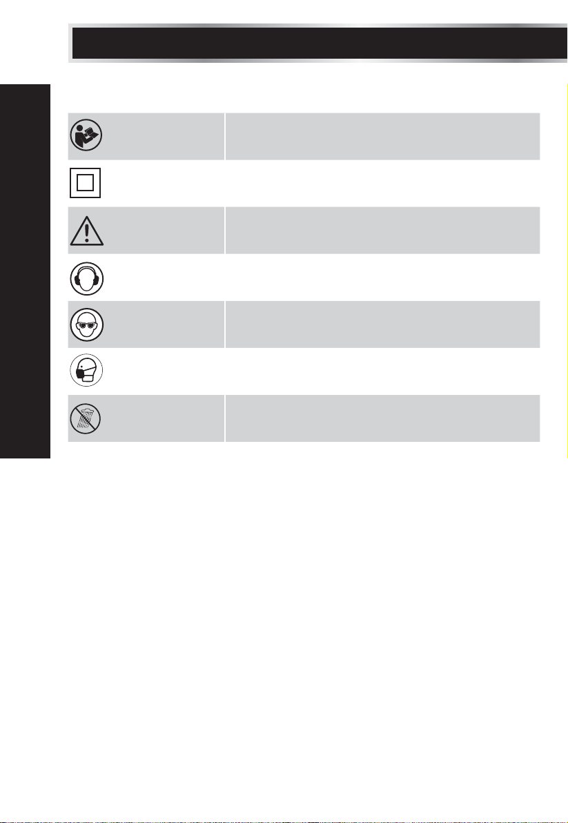
SYMBOLS
To reduce the risk of injury, user must read
instruction manual
Double insulation
Warning
Wear ear protection
Wear eye protection
Wear dust mask
Don’t use in the rain
Page 11
TM
11
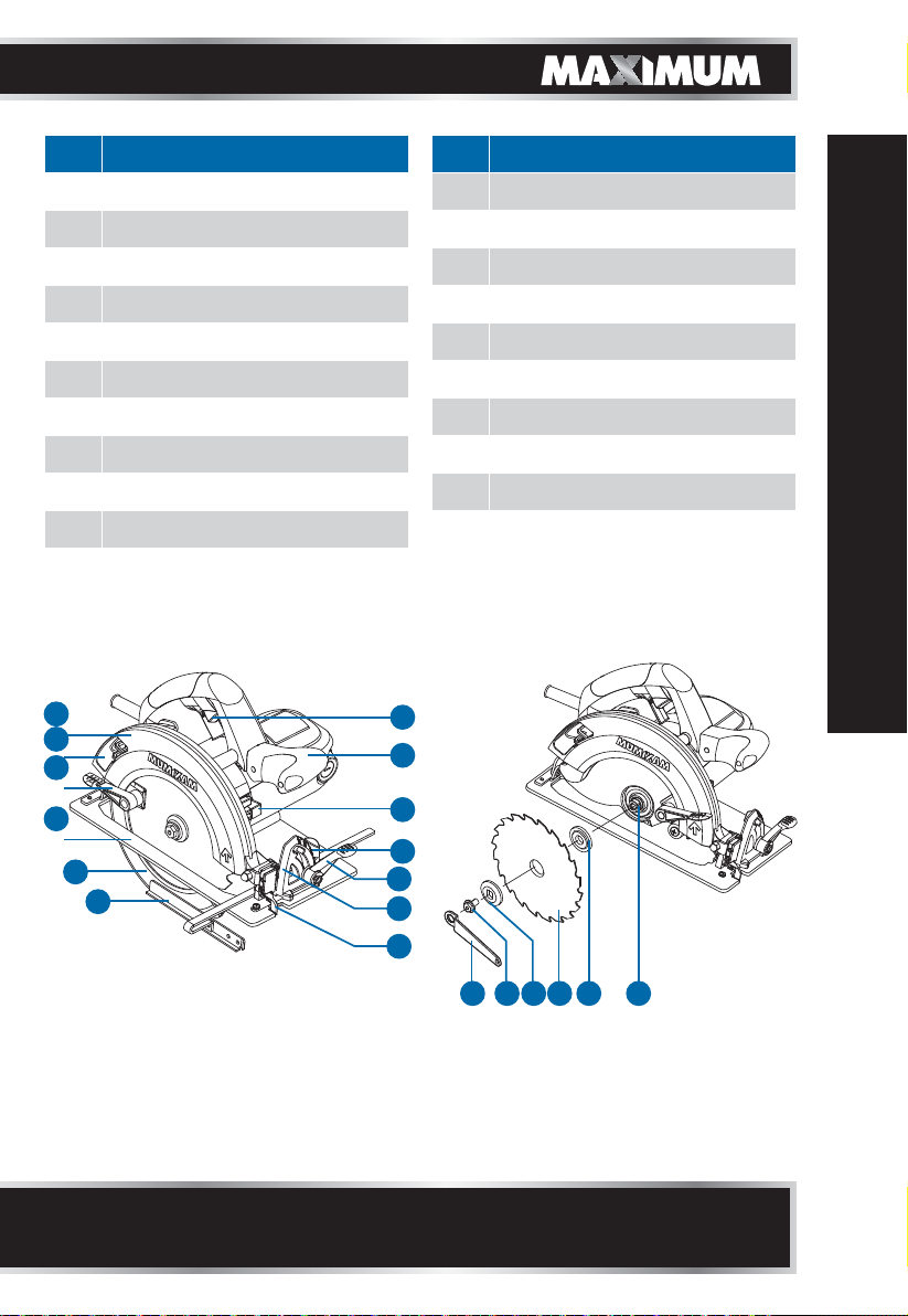
No. Description
1 On/off switch
2 Auxiliary handle
Spindle lock button
3
4 Base plate angle scale
5 Rip fence lock screw
6 Base plate bevel lock
7 Sight line
8 Rip fence
9 Lower blade guard
10 Base plate
11 Lower guard lever
13
12
11
No. Description
12 Dust extraction outlet
13 Fixed guard
14 Spindle
15 Inner flange
16 Saw blade
17 Outer flange
18 Blade bolt
19 Wrench
20 Depth-of-cut scale
21 Depth-of-cut lock lever
1
2
PARTS LIST
10
9
8
Not all the accessories illustrated or described are included in
standard delivery.
3
5
6
4
7
141516171819
Page 12

12
ACCESSORIES
model no. 054-8364-8 | contact us 1-888-670-6682
ACCESSORIES
Saw blade 1
Wrench 1
Rip fence 1
We recommend that you purchase your accessories from the same
store that sold you the tool. Use good quality accessories marked
with a well-known brand name. Choose the type according to the
work you intend to undertake. Refer to the accessory packaging for
further details. Store personnel can assist you and offer advice.
Page 13
TM
13
86
85
84
83
50
207
82
81
80
79
32
61
62
63
64
65
66
67
68
69
70
71
206
72
73
75
76
77
78
23
22
21
20
60
24
203
52
53
54
55
56
57
58
59
205
29
2
28
27
26
25
46
47
47
48
204
49
50
51
45
44
43
42
41
40
39
38
37
36
35
34
33
32
31
30
74
1
2
3
4
5
6
201
7
8
9
10
11
12
13
202
14
15
16
KNOW YOUR CIRCULAR SAW
17
18
19
Page 14
14
model no. 054-8364-8 | contact us 1-888-670-6682
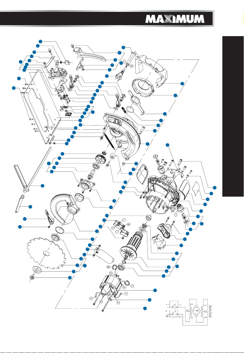
No. Description
1 Screw & washer assembly
2 Self-tapping screw
3 Brand lable
4 Side cover
5 Housing
6 Brush
7 Carbon brush
8 Brush cover
9 Self-tapping screw
10 Left auxiliary handle
11 Right auxiliary handle
12 Ball bearing race
13 Dustproof ring
14 Rotor
15 Ring
16 Ball bearing race
17 Stator
18 Connection board
19 Screw
20 Blade bolt
21 Outer flange
22 Saw blade
23 Inner flange
KNOW YOUR CIRCULAR SAW
24 Nut
25 Handle cover
26 Screw
27 Retaining ring
28 Lower guard
29 Switch
30 Bearing sleeve
31 Isolation cover
32 Self-tapping screw
33 Screw
34 Cord clamp
35 Self-tapping screw
36 Rubber ring
37 Side cover
38 Nut
39 Upper guard
40 Bolt
41 Compression spring
42 O-rings
43 Locking shaft piece
44 Baffle
45 Right handle
46 Cable protector
47 Rivet
No. Description
47 Rivet
48 Depth bracket
49 Rear support
50 Washer
51 Power cord
52 Snap ring
53 Nut
54 Lever
55 Washer
56 Washer
57 Screw
58 Pointer holder
59 Pointer
60 Compression spring
61 Top cover
62 Base plate
63 Bolt
64 Screw
65 Extension spring
66 Spring screw
67 Pointer cam
68 Screw
69 Ball bearing race
70 Gear
71 Ball bearing race
72 Spindle
73 Gear case cover
74 Cover
75 Guide ruler
76 Spanner
77 Movable guard handle
78 Screw
79 Screw
80 Rivet
81 Angle bracket
82 Front support
83 Fence
84 Bolt
85 Compression spring
86 Ruler locker
201 Carbon brush set
202 Rotor set
203 Saw blade
204 Depth bracket set (no accutrack)
205 Indicator set
206 Gear set
207 Angle bracket set (no accutrack)
Page 15
INTENDED USE
The machine is intended for ripping and crosscutting wood in straight cutting lines and with
bevel angles to 56°, while resting firmly on the
workpiece.
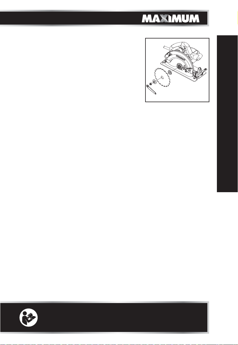
CHANGING THE SAW BLADE
• Before starting any work on the machine
itself, unplug the saw.
• Wear protective gloves when mounting the
saw blade. Danger of injury when touching
the saw blade.
• Only use saw blades that correspond with
the characteristic data given in the operating
instructions.
• Do not under any circumstances use grinding
discs as the cutting tool.
For changing the cutting tool, it is best to place
the machine on the face side of the motor
housing.
REMOVING (Fig. A)
TM
15
Fig. A
Press the spindle lock button (3) and keep it
depressed.
• The spindle lock button (3) may be actuated
only when the saw blade is at a standstill.
Loosen the blade bolt (18) with the spanner (19).
Remove the outer flange (17). Tilt back the lower
blade guard (9) and hold it firmly with the lower
guard lever (11). Remove the saw blade (16).
MOUNTING
Clean the saw blade and all the clamping parts to
be assembled. Tilt back the lower blade guard (9)
and hold it firmly with the lower guard lever (11).
Place the saw blade onto the inner flange (15).
Assemble the outer flange (17) and the blade bolt
(18). Use the wrench (19) to tighten the bolt (18)
with 1/4 turn more than finger tight.
• Take care that the mounting positions of the
NOTE: Before using the tool, read the instruction book
carefully.
OPERATING INSTRUCTIONS
Page 16
16
model no. 054-8364-8 | contact us 1-888-670-6682
inner flange (15) and outer flange (17) are
correct.
• When mounting, ensure that the cutting
direction of the teeth (direction of arrow
on saw blade) and the direction-of-rotation
arrow on the blade guard match.
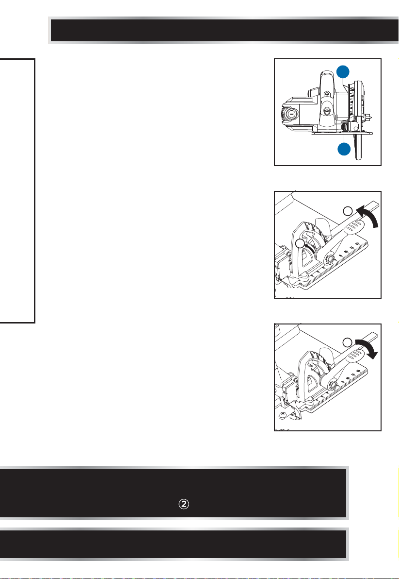
ADJUSTING THE CUTTING DEPTH (Fig. B)
To achieve an optimum cut, the saw blade must
not protrude beyond the material by more than
1/8” (maximum).
Lift the depth of cut lock lever (21) and raise the
saw body away from the base plate. Adjust the
required cutting depth using the depth of cut
scale (20). Turn the lock lever (21) in clockwise
direction to lock the set cutting depth.
ADJUSTING THE CUTTING ANGLE (Fig. C1,
C2)
Turn the base plate bevel lock (6) in counterclockwise direction to loosen the angle scale.
Tilt the base plate away from the machine until
the required cutting angle is adjusted on the
OPERATING INSTRUCTIONS
angle scale (4). Tighten the bevel lock (6) by
turning it in clockwise direction.
20
21
Fig. B
1
2
Fig. C1
3
Fig. C2
NOTE: The 45° mark has a fast and positive stop. You can use this
angle exactly. If you want to use a bigger cutting angle, you can
push the bevel lock along the path
and tighten the bevel lock.
NOTE: It is best to perform a practice cut prior to starting work.
Page 17
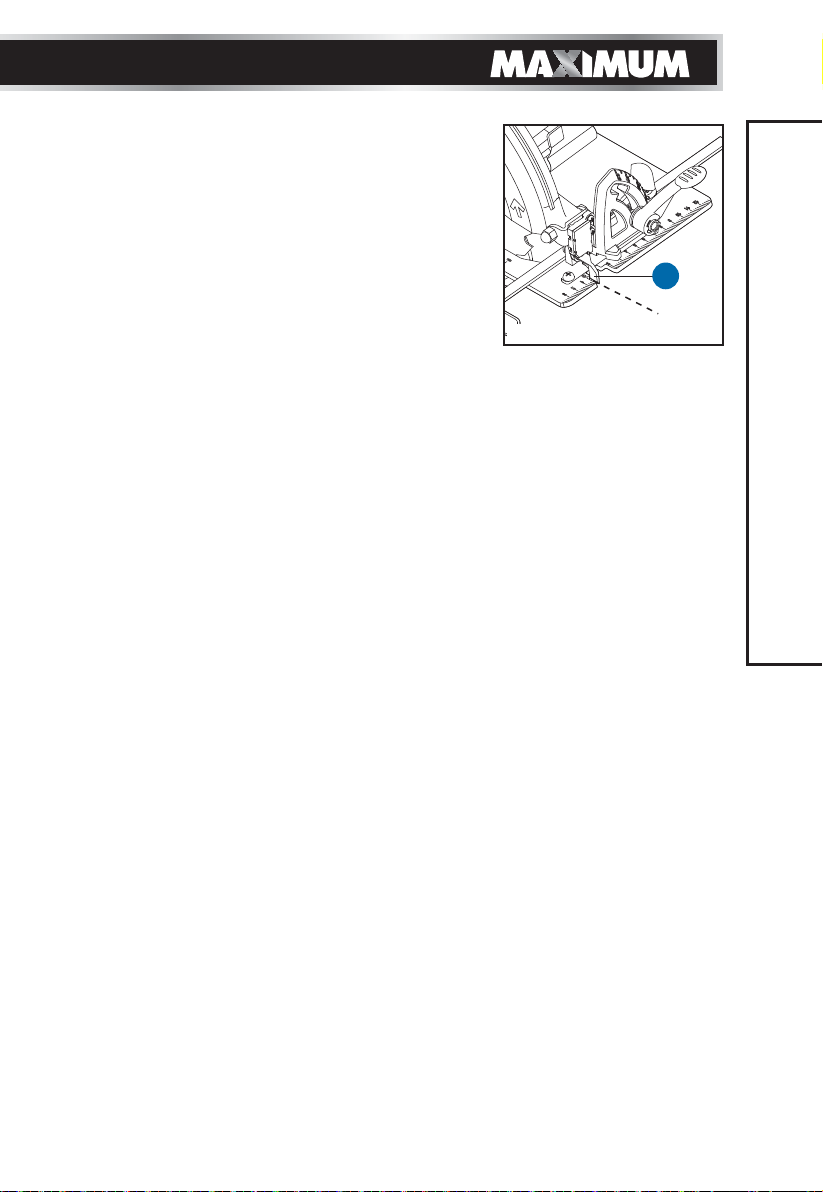
CUTTING GUIDE (Fig. D)
The sight line (7) fixed in front of the base plate
is used as a cutting guide. Always guide it along
the cutting mark made on the workpiece for
accurate cutting.
The cutting mark 0° indicates the position of the
saw blade for right-angled cuts.
SWITCHING ON AND OFF
Depress the on/off switch (1) to start the saw and
release to stop.
For safety reasons the on/off switch (1) of
the machine cannot be locked; it must remain
pressed during the entire operation.
TM
17
7
Fig. D
OPERATING INSTRUCTIONS
Page 18

18
WORKING HINTS FOR YOUR CIRCULAR SAW
model no. 054-8364-8 | contact us 1-888-670-6682
WORKING HINTS FOR YOUR CIRCULAR
SAW
If your power tool becomes too hot, please run your
circular saw no-load for 2-3 minutes to cool the
motor. Avoid prolonged usage at very low speeds.
Protect saw blades against impact and shock.
Excessive feed significantly reduces the
performance capability of the machine and
reduces the service life of the saw blade. Sawing
performance and cutting quality depend on the
condition and the tooth count of the saw blade.
Therefore, use only sharp saw blades that are
suited for the material to be worked.
Choice of blades: 24 teeth for general work,
approx. 40 teeth for finer cuts, more than 40
teeth for very fine cuts into delicate surfaces.
Fig. E
RIP FENCE (Fig. E)
The rip fence (8) enables exact cuts along a
workpiece edge and cutting strips of the same
dimension.
Fig. F
BEVEL CUTS (Fig. F)
Set required bevel angle between 0° and 56°.
Do not use the depth-of-cut scale when making
bevel cuts due to possible inaccuracy.
POCKET CUTTING (SOFT MATERIALS ONLY)
(Fig. G1, G2)
This operation requires much skill with a saw and
must only be carried out by a competent person.
Clearly mark the area to be cut. Set the depth of
cut on the saw. Position the saw over the marked
area with the front edge of the base plate resting
on the work surface and cutting guide aligned
with marked line on workpiece. Ensure the blade
is not touching but is close to the work surface.
The moving lower blade guard (9) must be
rotated open by using the lower guard lever (11).
Switch the saw on and gently swing the blade
down into the material but maintain a pivoting
force on the front edge of the base. The moving
lower blade guard can now be released for
normal action of the guard.
Fig. G1
Fig. G2
WARNING!
The blade teeth are exposed during this operation so
proceed with extreme caution.
Page 19
TM
MAINTENANCE
Remove the plug from the socket before carrying out any adjustment,
servicing or maintenance.
Your tool requires no additional lubrication or maintenance. There are no
user serviceable parts in your power tool. Never use water or chemical
cleaners to clean your power tool. Wipe clean with a dry cloth. Always
store your power tool in a dry place. Keep the motor ventilation slots
clean. Keep all working controls free of dust. Occasionally you may see
sparks through the ventilation slots. This is normal and will not damage
your power tool.
If the supply cord is damaged, it must be replaced by the manufacturer, its
service agent or similarly qualified persons in order to avoid a hazard.
19
MAINTENANCE
Page 20
20
WARRANTY
model no. 054-8364-8 | contact us 1-888-670-6682
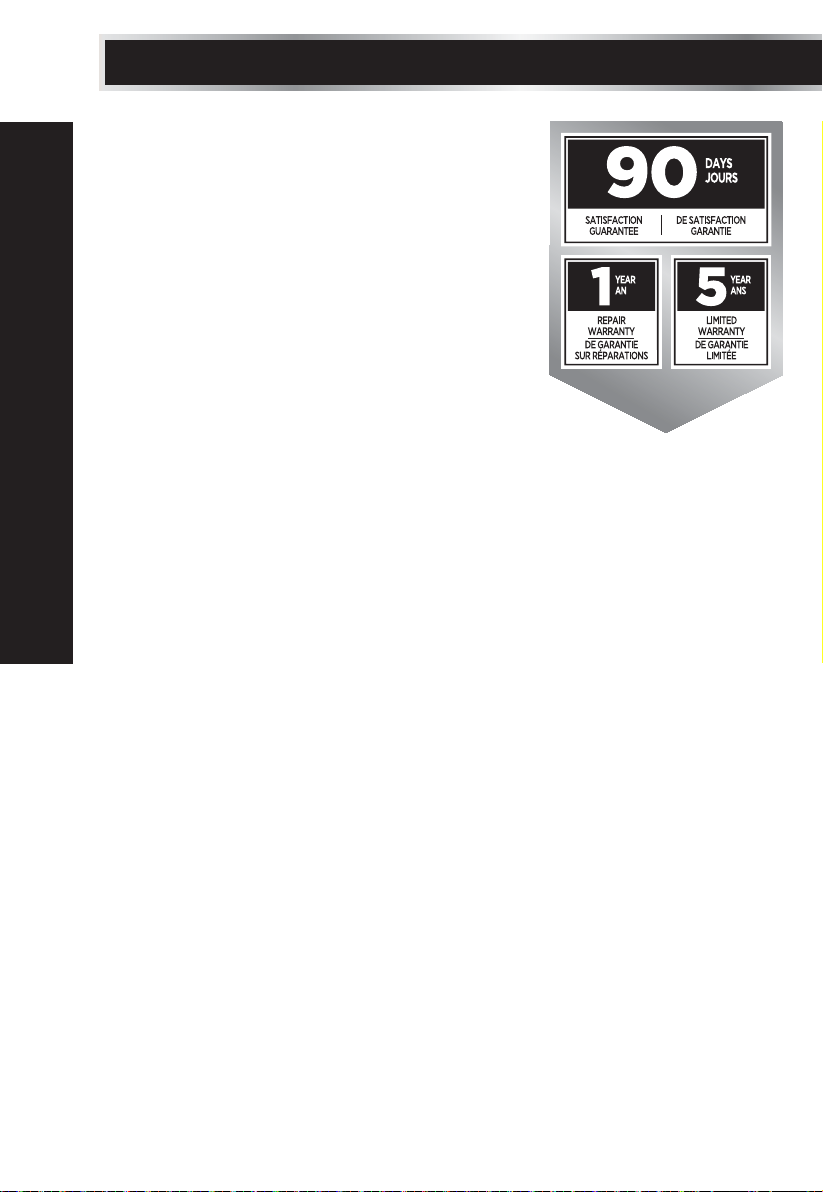
This MAXIMUM product is guaranteed for a period of 5
years from the date of original retail purchase against
defects in workmanship and materials only and is
subject to the following components:
a) Component A: Batteries/chargers can be repaired
or replaced due to defects in workmanship and
materials for a period of 3 years from the date of
original retail purchase;
b) Component B: The carrying case is guaranteed for
a period of 1-year from the date of original retail
purchase against defects in workmanship and
materials.
c) Component C: Accessories, including drill bits and
saw blades, do not carry a warranty.
Subject to the conditions and limitations described below, this product, if returned
to us with proof of purchase within the stated warranty period and if covered
under this warranty, will be repaired or replaced (with the same model, or one
of equal value or specification), at the sole discretion of the Maximum Canada
authorized repair centre (“Service Provider”). We will bear the cost of any repair or
replacement and any costs of labour relating thereto.
These warranties are subject to the following conditions and limitations:
a) a bill of sale verifying the purchase and purchase date must be provided;
b) defects in workmanship and material to be assessed and determined by the
Service Provider
c) this warranty will not apply to any product or part thereof which is worn or
broken or which has become inoperative due to abuse, misuse, accidental
damage, neglect or lack of proper installation, operation or maintenance (as
outlined in the applicable owner’s manual or operating instructions);
d) this warranty does not apply to normal wear and tear or to expendable parts
or accessories (including drill bits and saw blades) that may be supplied with
the product that by their nature have a limited life span and are expected to
become inoperative or unusable after a reasonable period of use;
e) this warranty will not apply to routine maintenance and consumable items such
as, but not limited to, fuel, lubricants, vacuum bags, blades, belts, sandpaper,
bits, fluids, rubber o-rings, tune-ups or adjustments;
f) this warranty excludes the following components that may accompany your
product:
(1) Batteries/chargers, which can be repaired or replaced due to defects in
workmanship or materials for a period of 3 years from the date of original retail
purchase. Any defects with such battery and/or charger will be subject to repair
or replacement as determined by the Service Provider.
(2) The carrying case, which is only for a period of 1-year from the date of
original retail purchase against defects in workmanship and materials.
(3) Accessories, including drill bits and saw blades, which do not carry a
warranty of any kind.
g) this warranty will not apply where damage is caused by repairs made or
Page 21
TM
attempted by anyone other than the Service Provider (i.e. persons not
authorized by the manufacturer), and any such unauthorized repairs or
attempted repairs shall void this warranty in its entirety;
h) this warranty will not apply to any parts other than original parts, except to the
extent that the retailer or manufacturer or persons authorized by either of them
have repaired or replaced them;
i) this warranty will not apply to any product that was sold to the original
purchaser as a reconditioned or refurbished product (unless otherwise specified
in writing);
j) this warranty will not apply to any product or part thereof if any part from
another manufacturer is installed therein or any repairs or alterations have been
made or attempted by unauthorized persons;
k) this warranty will not apply to normal deterioration of the exterior finish, such
as, but not limited to, scratches, dents, paint chips, or to any corrosion or
discolouring by heat, abrasive and chemical cleaners; and
l) this warranty will not apply to component parts sold by and identified as
the product of another company, which shall be covered under that product
manufacturer’s warranty, if any;
m) any products replaced by the retailer in attempt to fulfill warranty obligations is
subject to the original product warranty conditions and related time period as
initiated by the original date of purchase; if product is purchased in Quebec, the
warranty term will be extended for a period equal to the time during which the
Quebec retailer possesses the product in attempt to fulfill warranty obligations;
replaced product will not default to new product warranty conditions; and
n) The retailer and manufacturer’s sole obligation and the purchaser’s sole remedy
under this warranty shall be as set out herein. The warranties contained herein
are not transferable and are given only to the purchaser. FURTHER, THE
WARRANTIES SET OUT HEREIN ARE IN LIEU OF ALL OTHER WARRANTIES
OR CONDITIONS, WHETHER EXPRESS, IMPLIED OR STATUTORY (INCLUDING
SUCH AS ARISE UNDER THE SALE OF GOODS ACT OR THE INTERNATIONAL
SALE OF GOODS ACT), ARISING OUT OF A COURSE OF DEALING OR USAGE
OF TRADE OR OTHERWISE, INCLUDING, SUBJECT TO APPLICABLE LAW,
ANY IMPLIED WARRANTIES OR CONDITIONS OF MERCHANTABILITY,
MERCHANTABLE QUALITY, FITNESS OR ADEQUACY FOR A PARTICULAR
PURPOSE OR USE, AND ALL OTHER SUCH WARRANTIES ARE EXPRESSLY
DISCLAIMED BY THE RETAILER AND MANUFACTURER.
21
WARRANTY
ADDITIONAL LIMITATIONS
This warranty applies only to the original purchaser and may not be
transferred.
This warranty applies for a period of 5 years from the date of original retail
purchase, as indicated on the bill of sale.
Neither the retailer, Maximum Canada, nor the manufacturer shall be
liable for any other expense, loss or damage, including, without limitation,
any indirect, incidental, consequential or exemplary damages arising in
connection with the sale, use or inability to use this product.
Under no circumstances shall the retailer, Maximum Canada, or manufacturer
Page 22
22
model no. 054-8364-8 | contact us 1-888-670-6682
be liable to the purchaser for any claim for (a) indirect, special, punitive,
incidental, exemplary, or consequential damages, (b) compensation for loss of
profits, anticipated revenue, savings or goodwill, or other economic loss of the
purchaser, (c) exemplary, aggravated or punitive damages howsoever incurred,
(d) contribution or set-off in respect of any claims against the purchaser, (e) any
damages whatsoever relating to third party products or services or the purchaser’s
materials, or (f) any damages whatsoever relating to interruption, delays, errors
or omissions; in each case under any theory of law or equity, arising out of or
in any way related to this warranty, even if advised of the possibility thereof.
Notwithstanding any provision herein or entitlement of the purchaser at law, in
equity or otherwise, in no event shall the liability of the retailer or manufacturer
under this warranty, whether in contract, tort, product liability or otherwise, exceed,
in the aggregate, the amount paid by the purchaser to the retailer for the product to
which this warranty applies.
NOTICE TO CONSUMER
This warranty gives you specific legal rights, and you may have other rights, which
may vary from province to province. The provisions contained in this warranty are
not intended to limit, modify, take away from, disclaim or exclude any statutory
warranties set forth in any applicable provincial or federal legislation.
In addition to the 5-Year Limited Warranty, this MAXIMUM product is covered by
our:
WARRANTY
Maximum Canada will maintain this product and replace critical parts which have
worn beyond reasonable use through normal use of such product, any time during
the first year after purchase.
The following are excluded from this 1-Year Repair Warranty:
a) Missing or damaged parts or components that are a result of abuse or misuse;
b) Any wear and tear to non-critical parts or accessories that do not affect the
core function of the product.
1-YEAR REPAIR WARRANTY
90-DAY SATISFACTION GUARANTEE
If you are not completely satisfied with the performance of your MAXIMUM product
for any reason, you can return it within 90 days from the date of purchase with
proof of purchase for exchange or a full refund.
Imported by MAXIMUM Canada Toronto, Canada M4S 2B8
Made in China
 Loading...