

Page 1

Plunge/Fixed-base Router
model no. 054-6810-8
IMPORTANT:
Please read this manual carefully before
using this product, and save it for reference.
INSTRUCTION
MANUAL
Page 2

Page 3

TABLE OF CONTENTS
Technical Specifications 4
Safety Guidelines 5
Key Parts Diagram 10
Important Information 12
Assembly Instructions 14
Operating Instructions 20
Maintenance 28
Troubleshooting 29
Part list 30
Warranty 34
3
TABLE OF CONTENTS
NOTE: If any parts are missing or damaged, or if you
have any questions, please call our toll-free helpline at
1-888-670-6682.
SAVE THESE INSTRUCTIONS
• This manual contains important safety and
operating instructions. Read all instructions
and follow them with use of this product.
Page 4

4
TECHNICAL SPECIFICATIONS
model no. 054-6810-8 | contact us 1-888-670-6682
TECHNICAL SPECIFICATIONS
Rated voltage 120V ~ 60 Hz
Rated power input 11A
Horsepower 2.0 HP
No-load speed 11,000–25,000 RPM
Collet capacity 1/4 & 1/2"
Plunge stroke 2"
Base dimensions Fixed base 6"
Plunge base 6 1/2"
Inside base diameter 2"
Micro-fine depth Fixed base adjusts to 1/64"
Plunge base adjusts to 1/256"
Weight 12 lb (5.4 kg)
Page 5
RULES FOR SAFE OPERATION
KNOW YOUR TOOL
To operate this tool, carefully read this Instruction Manual and all labels affixed
to the Plunge/Fixed-base Router. Keep this Manual available for future reference.
IMPORTANT
This tool should only be serviced by a qualified service technician. For more
information, call the toll free helpline at 1-800-689-9928.
READ ALL INSTRUCTIONS CAREFULLY
SAVE THESE INSTRUCTIONS
GENERAL POWER TOOL SAFETY WARNINGS
WARNING!
Read all safety warnings and instructions. Failure to follow the warnings
and instructions may result in electric shock, fire and/or serious injury.
SAVE ALL WARNINGS AND INSTRUCTIONS FOR FUTURE REFERENCE.
The term “power tool” in the warnings refers to your mains-operated (corded)
power tool or battery-operated (cordless) power tool.
WORK AREA SAFETY
• Keep the work area clean and well lit. Cluttered or dark areas invite accidents.
• Do not operate power tools in explosive atmospheres, such as in the presence
of flammable liquids, gases or dust. Power tools create sparks, which may
ignite the dust or fumes.
• Keep children and bystanders away while operating a power tool. Distractions
can cause you to lose control.
5
SAFETY GUIDELINES
ELECTRICAL SAFETY
• Power tool plugs must match the outlet. Never modify the plug in any way. Do
not use any adapter plugs with earthed (grounded) power tools. Unmodified
plugs and matching outlets will reduce the risk of electric shock.
• Avoid body contact with earthed or grounded surfaces such as pipes,
radiators, ranges and refrigerators. There is an increased risk of electric shock
if your body is earthed or grounded.
• Do not expose power tools to rain or wet conditions. Water entering a power
tool will increase the risk of electric shock.
Page 6

model no. 054-6810-8 | contact us 1-888-670-6682
6
• Do not abuse the cord. Never use the cord for carrying, pulling or unplugging
the power tool. Keep the cord away from heat, oil, sharp edges or moving
parts. Damaged or entangled cords increase the risk of electric shock.
• When operating a power tool outdoors, use an extension cord suitable for outdoor
use. Use of a cord suitable for outdoor use reduces the risk of electric shock.
• If operating a power tool in a damp location is unavoidable, use a ground-fault
circuit interrupter (GFCI) protected supply. Use of a GFCI reduces the risk of
electric shock.
PERSONAL SAFETY
• Stay alert, watch what you are doing and use common sense when operating
a power tool. Do not use the tool while tired or under the influence of drugs,
alcohol, or medication. A moment of inattention while operating power tools
may result in serious personal injury.
• Use personal protective equipment. Always wear eye protection. Protective
equipment such as dust mask, non-skid safety shoes, hard hat, or hearing
protection, used for appropriate conditions, will reduce personal injuries.
• Prevent unintentional starting. Ensure the switch is in the off-position before
connecting to power source and/or battery pack, picking up or carrying the
tool. Carrying power tools with your finger on the switch or energising power
tools that have the switch on invites accidents.
• Remove any adjusting key or wrench before turning the power tool on. A
SAFETY GUIDELINES
wrench or a key left attached to a rotating part of the power tool may result in
personal injury.
• Do not overreach. Keep proper footing and balance at all times. This enables
better control of the power tool in unexpected situations.
• Dress properly. Do not wear loose clothing or jewellery. Keep your hair,
clothing and gloves away from moving parts. Loose clothes, jewellery or long
hair can be caught in moving parts.
• If devices are provided for the connection of dust extraction and collection
facilities, ensure that these are connected and properly used. Use of these
devices can reduce dust-related hazards.
POWER TOOL USE AND CARE
• Do not force the power tool. Use the correct power tool for your application.
The correct power tool will do the job better and more safely at the rate for
which it was designed.
• Do not use the power tool if the switch does not turn it on and off. Any power
tool that cannot be controlled with the switch is dangerous and must be repaired.
• Disconnect the plug from the power source and/or the battery pack from the
power tool before making any adjustments, changing accessories, or storing
power tools. Such preventive safety measures reduce the risk of starting the
power tool accidentally.
Page 7

• Store idle power tools out of the reach of children and do not allow persons
unfamiliar with the power tool or these instructions to operate the power tool.
Power tools are dangerous in the hands of untrained users.
• Maintain power tools. Check for misalignment or binding of moving parts,
breakage of parts and any other condition that may affect the power tool’s
operation. If damaged, have the power tool repaired before use. Many
accidents are caused by poorly maintained power tools.
• Keep cutting tools sharp and clean. Properly maintained cutting tools with
sharp cutting edges are less likely to bind and are easier to control.
• Use the power tool, accessories, tool bits, etc. in accordance with these
instructions, taking into account the working conditions and the work to be
performed. Use of the power tool for operations different from those intended
could result in a hazardous situation.
SERVICE
• Have your power tool serviced by a qualified repair person using only
identical replacement parts. This will ensure that the safety of the power tool
is maintained.
SPECIFIC SAFETY RULES FOR ELECTRIC ROUTERS
• Hold power tool by insulated gripping surfaces, because the cutter may
contact its own cord. Cutting a “live” wire may make exposed metal parts of
the power tool “live” and shock the operator.
• Use clamps or another practical way to support the workpiece and secure it to
a stable platform. Holding the work by your hand or against the body leaves it
unstable and may lead to loss of control.
• Always wear a dust mask and ear protection when using this power tool.
• Only use cutters that are designed for this router. Never use router bits with
a diameter exceeding the maximum diameter specified in the technical data
section.
• Only use sharp cutters that are not chipped or cracked. Blunt cutters will
cause stalling.
• Secure small pieces of wood firmly before working. Never hold a workpiece in
your hand.
• Keep your hands away from the cutting area.
• Before starting the router, check that the cutter is firmly positioned and
secured in the collet.
• Do not exceed the maximum indicated rotation speed of the cutter.
• Routing operations must always be performed against the direction of
rotation (cutter-rotation) of the cutter.
• The cutter must be running at full speed before it is lowered to the workpiece.
7
SAFETY GUIDELINES
Page 8

model no. 054-6810-8 | contact us 1-888-670-6682
8
• When operating the router, always hold the handles firmly with both hands.
Always ensure that your footing is secure when working.
• Be prepared for the reaction torque of the router, particularly if the cutter
becomes jammed in the workpiece.
• When a plunge-cutting operation is completed, release the handle to allow
the router to rise back to its initial position.
• Familiarize yourself with your working area, and be alert for possible hazards
that you may not hear due to the noise of the router.
• Allow sufficient run-down time for the cutter after turning the router off. Wait
for it to come to a complete stop before removing it from the workpiece.
• Never slow the router down with your hands.
• Do not touch the cutter immediately after operation. It may be extremely hot
and could burn you.
• Never stop the router by applying lateral pressure to the cutter.
• Do not force the router. It will do a better job if you allow it to work at its
intended speed.
• Avoid cutting nails and screws. Inspect timber before cutting, and remove all
nails and screws.
• In the event of an electrical or mechanical malfunction, switch the router off
SAFETY GUIDELINES
immediately, and disconnect the power cord from the outlet.
• Only use router bits suitable for the no-load speed of the tool.
• Always use cutter bits that are designed for this router. Never use cutter bits
which are larger in diameter than the opening in the router base. Cutter bits
that have cutter diameters larger than the opening could cause possible loss of
control or create other hazardous condition that could cause serious personal
injury.
Page 9
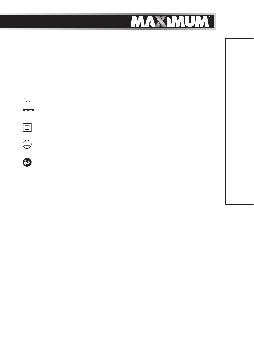
• The label on your tool may include the following symbols. The symbols
and their definitions are as follows:
V ..................... Volts
A ..................... Amperes
Hz ................... Hertz
W .................... Watts
min ................. Minutes
............... Alternating current
............. Direct current
n
................... No-load speed
0
............... Class II Construction
…/min ........... Revolutions or reciprocation per minute
............... Grounding terminal
BPM ............... Beats per minute
.............. WARNING – To reduce the risk of injury, user must read
instruction manual.
9
SAFETY GUIDELINES
Page 10
10
model no. 054-6810-8 | contact us 1-888-670-6682
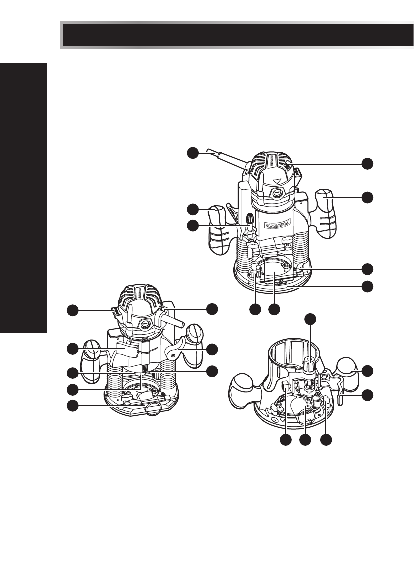
PACKAGE CONTENTS:
Router, plunge base, fixed base, 2 self-releasing collets (1/2" & 1/4"), collet
wrench, straight-edge guide, pattern guide, 2 dust-extraction adaptors, chip
shield, screws, and instruction manual
KEY PARTS DIAGRAM
11
12
10
10
9
13
14
KEY PARTS DIAGRAM
1
2
3
4
5
8
7
6
15 18
16
10
2
17 135
Page 11
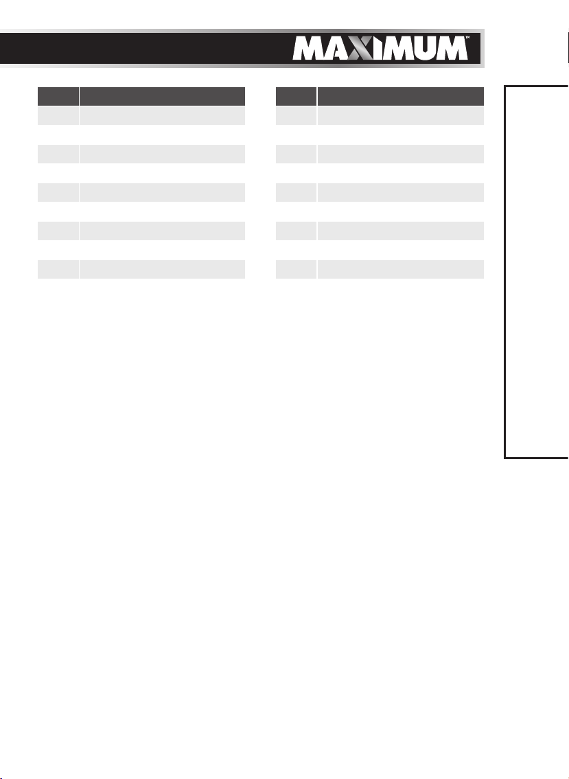
NO. PART NO. PART
1 ON/OFF switch 10 Handle
2 Lock lever 11 Cable
3 Spindle lock 12 Variable-speed dial
4 Collet 13 Lock nut
5 Dust-extraction adaptor 14 Base plate
6 LED worklight 15 Depth stop
7 Locking arm 16 Depth-adjustment knob
8 Live tool indicator 17 Adjustment button
9 Adjustment bar 18 Chip shield
11
KEY PARTS DIAGRAM
Page 12
12
model no. 054-6810-8 | contact us 1-888-670-6682
IMPORTANT INFORMATION
Before attempting to use this router, familiarize yourself with all of its operating
features and safety requirements. This electric router is designed to be used only
for milling and edge forming in wood or similar materials. Any other use of the
router that is not indicated in this manual could damage the router or seriously
injure the operator and, therefore, is expressly excluded from the application
range.
SOFT-START FEATURE
The soft-start feature minimizes torque twist, which is customary in larger router
motors, by limiting the speed at which the motor starts. This increases the life of
the motor.
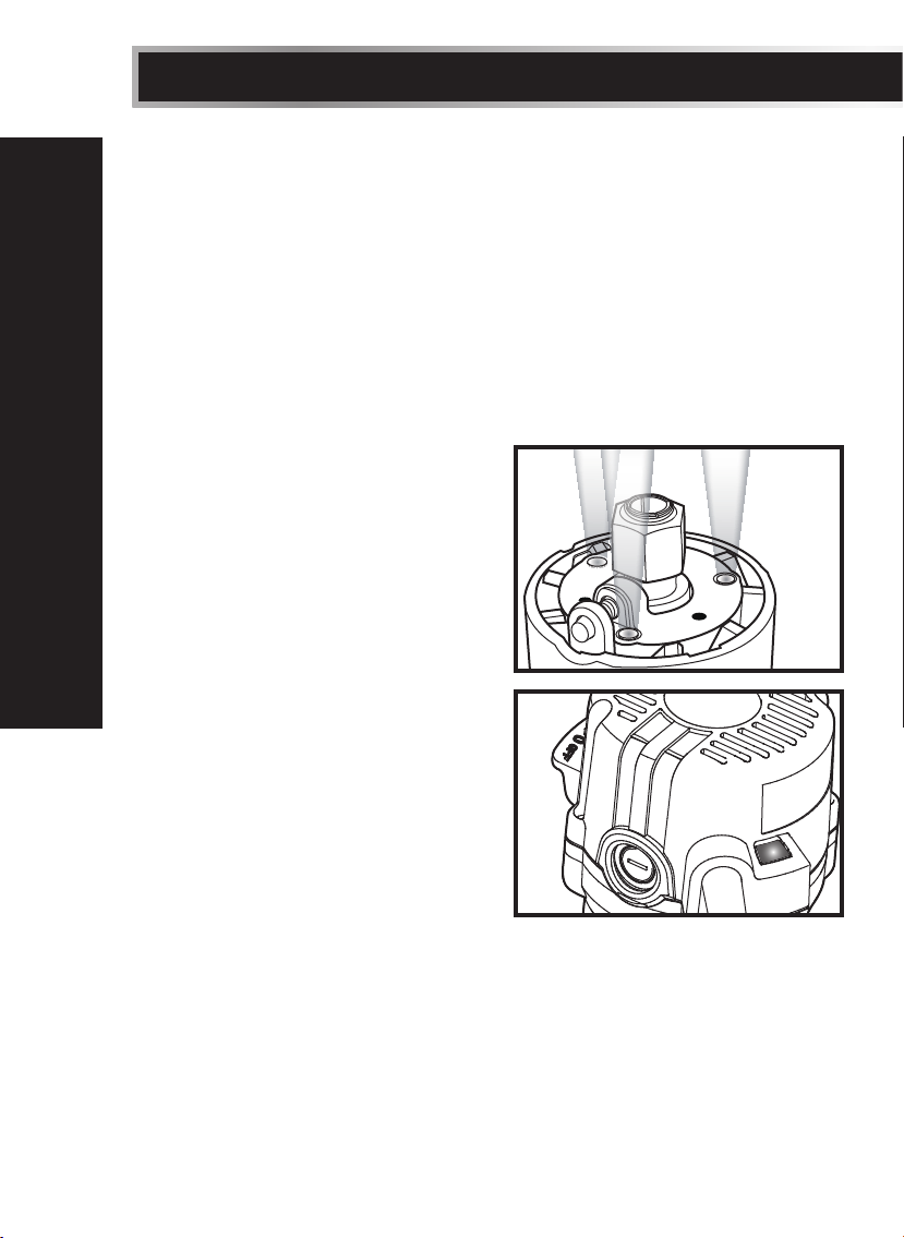
LED WORKLIGHTS (g 1)
The router motor has 3 built-in
worklights located around the collet;
these provide high visibility of the
workpiece when cutting. These lights are
always “ON” when the toggle switch is in
the “on” position.
“LIVE TOOL INDICATOR”
LIGHT (g 2)
IMPORTANT INFORMATION
The router also has a green “LIVE TOOL
INDICATOR” light located on the motor
housing top cap where the power cord
enters the motor housing. This green
light is always on when router motor is
plugged into a power source.
HEAVY-DUTY EDGE GUIDE
This Fixed-base Router comes with
a Heavy-duty Edge Guide. This edge
guide can be used as an aid in routing
applications such as decorative edging, straight-edge planing and trimming,
grooving, dadoing, and slotting.
g 1
g 2
Page 13
13
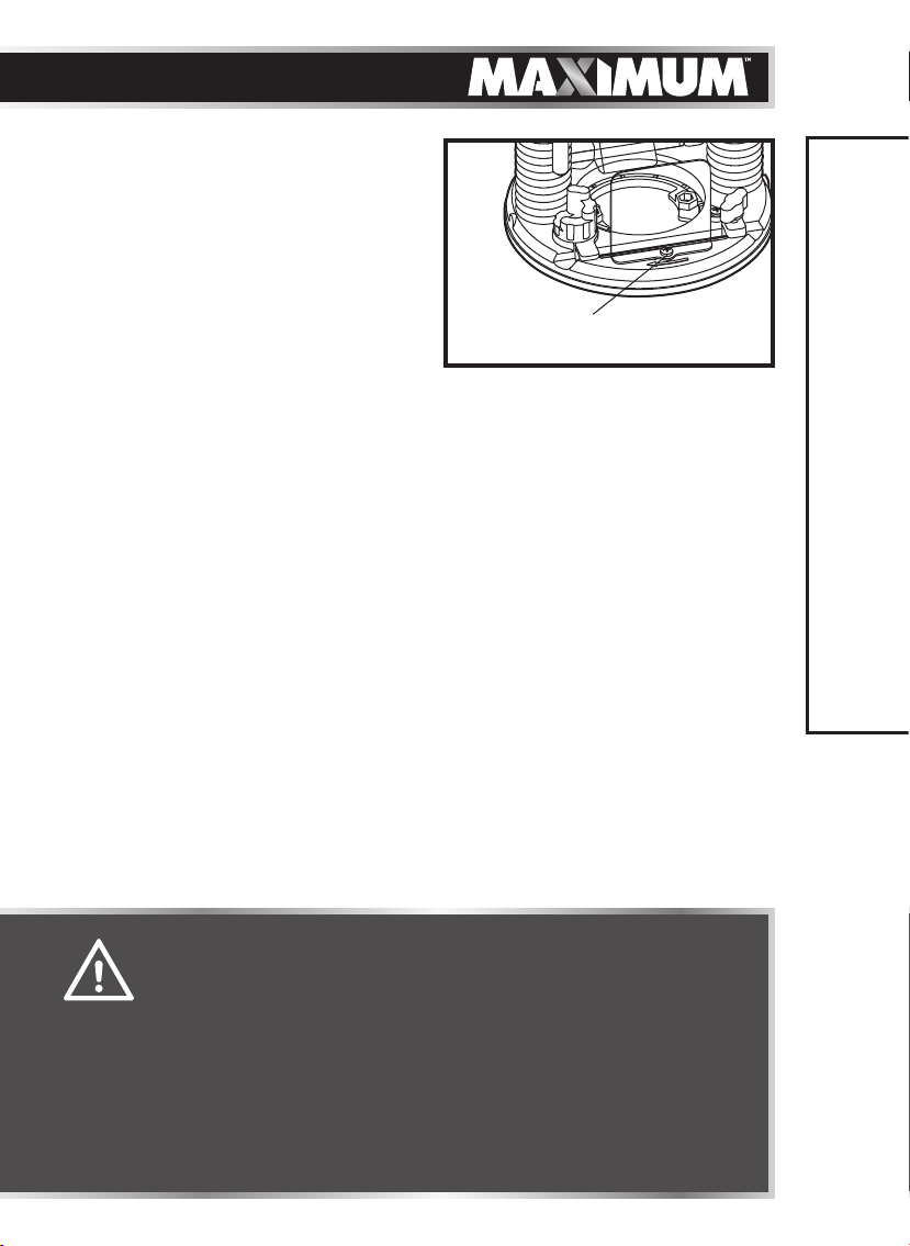
CHIP SHIELD (g 3)
The chip shield helps to keep dust and
chips away from the operator; it will
not stop objects larger than woodchips
thrown from the bit.
g 3
Screw (Included)
IMPORTANT INFORMATION
WARNING!
• Always wear eye protection. The chip shield deflector is not
intended as a safety guards.
• Always turn the router motor off and unplug router from
the power source before making any adjustments, installing
accessories or performing maintenance. Failure to turn the motor
off and unplug the router could result in accidental starting,
which can cause serious personal injury.
CAUTION!
• Always have the chip shield deflector in place on the base when
operating the router.
Page 14
14
model no. 054-6810-8 | contact us 1-888-670-6682
ASSEMBLY INSTRUCTIONS
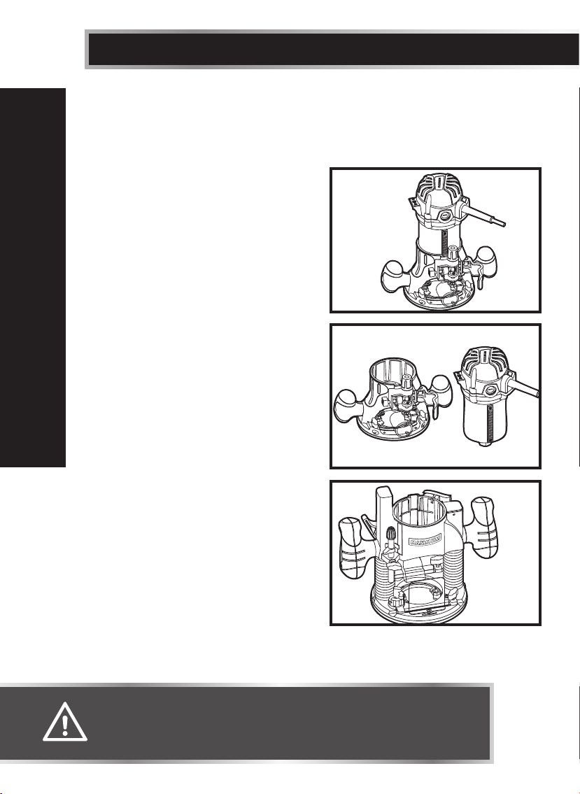
SWITCHING FROM THE FIXED BASE TO THE PLUNGE BASE
(see g 4 to g 7)
To remove the fixed base
1. Unplug the router.
2. Loosen the lock lever on the fixed
base.
3. Hold the motor pack with one hand,
and depress and hold the adjustment
button with the other hand.
4. Remove the motor pack from the fixed
base.
g 4
To Install the plunge base
1. Unplug the router.
2. Loosen the lock lever
3. Tighten the locking arm for stability.
4. Align the tab on the motor pack with
ASSEMBLY INSTRUCTIONS
the slot in the plunge base.
5. Tighten the lock lever.
6. Loosen the locking arm.
To install the chip shield on the plunge
base
The chip shield on the plunge base is held
in position with a screw. To remove the
chip shield from the plunge base, unplug
the router and simply loosen the screw
and take the chip shield off of the base
(fig 3).
WARNING!
• Always unplug the tool from the power source before making any
adjustment or attaching accessories.
g 5
Fixed Base
g 6
Motor
Plunge
base
Page 15
SWITCHING FROM THE PLUNGE BASE TO THE FIXED BASE
(see g 4 to g 7)
15
To remove the plunge base
1. Unplug the router.
2. Loosen the lock lever.
3. Tighten the locking arm for stability.
4. Remove the motor pack from the
plunge base.
To install the fixed base
1. Unplug the router.
2. Loosen the lock lever on the fixed base.
3. Depress and hold the adjustment button.
4. Align the tab on the motor pack with the slot in the fixed base.
5. Tighten the lock lever.
INSTALLING/REMOVING THE CUTTER
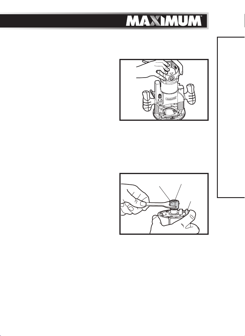
To install the cutter (see fig 8)
1. Unplug the router.
2. Hold the collet nut with the wrench
that is provided and depress the
spindle lock button until the spindle
locks into place.
3. Loosen the collet nut with the wrench
and remove the cutter. Insert the new
cutter.
4. Tighten the collet nut with the wrench that is provided.
5. Release the spindle lock button.
g 7
g 8
Nut
Collet
ASSEMBLY INSTRUCTIONS
Spindle
Lock
To remove the cutter
1. Unplug the router.
2. Hold the collet nut with the wrench that is provided and depress the spindle
lock button until the spindle locks into place.
3. Loosen the collet nut with the wrench and remove the cutter.
4. Release the spindle lock button.
Page 16
16
model no. 054-6810-8 | contact us 1-888-670-6682
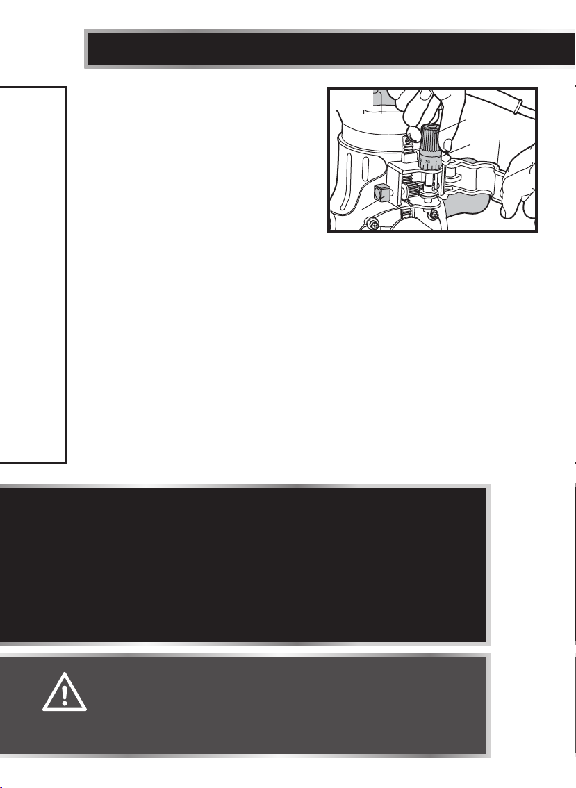
SETTING THE CUTTING DEPTH FOR
FIXED BASE ROUTING (see g 9)
The fixed base is designed with a
micro-fine adjustment worm-gear
system. When the bit is lowered to the
approximate desired position (rough
setting), the system can then be
micro-adjusted to the precise depth.
Rough Adjustment:
Depressing the Rough-adjustment Knob (B) allows the operator to quickly lower
or raise the cutter bit to an approximate depth setting.
Micro-fine Adjustments:
The Depth-indicator Ring (D) is located on the Micro-fine Adjustment Dial, and
is marked in 1/64" increments. Turning the Micro-fine Adjustment Dial clockwise
180° (1/2 turn), lowers the cutter bit 1/16". One full turn clockwise (360°) - zero
“0” to zero “0” - lowers the bit 1/8".
The system allows a maximum of 7 full 360° clockwise revolutions in order to
lower the cutter bit 7/8" (22.3 mm). The Depth-indicator Ring may be reset to
zero “0” without moving the Micro-fine Adjustment Dial. This allows the user to
begin adjustments from any desired reference point.
ASSEMBLY INSTRUCTIONS
g 9
B
C
A
D
NOTICE:
• All depth adjustments on the fixed base must be made with the motor
clamp loosened.
• For all fixed-base routers, the cutter bit depth equals the amount of the
cutter that is exposed below the surface of the sub-base.
• Be sure the worm-gear system is engaged before making fine adjustments.
Test it by turning the Micro-fine Adjustment Dial (C) clockwise and counterclockwise to see if the bit lowers and rises. If it does not, press the Roughadjustment Knob, and turn the Micro-fine Adjustment Dial until the gears
engage, and then reset zero “0” on Depth-indicator Ring (D).
WARNING!
• Ensure that the router is never turned on or connected to the
power source when assembling parts, making adjustments, or
installing or removing collets and cutter bits, during cleaning,
or when it is not in use. Disconnecting the router will prevent
accidental start-ups, which could cause serious personal injury.
Page 17

Adjusting the depth
1.
Turn the motor off, and unplug the tool from the power source.
2. Place the router on a flat, level surface, with the back of the fixed base facing
the operator.
3. Loosen the Motor Clamp (A).
4. With the cutter bit already installed, press the Rough-adjustment Knob (B),
and lower the motor into the base until the cutter bit is very close to the flat
surface on which the base is sitting.
5. Turn the Micro-fine Adjustment Dial (C) until the cutter bit “just” touches the
flat surface on which the base is sitting.
6. Tighten the motor clamp.
7. While continuing to press the Rough-adjustment Knob, turn the Micro-fine
Adjustment Dial until the zero “0” mark on the Depth-indicator Ring is lined
up with the “I” mark on the base.
8. Release the Rough-adjustment Knob, making sure that the “0” remains
aligned with the mark.
9. Place the router on two level scrap workpieces, positioned so that the cutter
bit can be lowered below the sub-base.
10. Turn the Micro-fine Adjustment Dial clockwise to lower the bit to the desired
cutting depth. Turn the dial counter-clockwise in order to raise the cutter bit.
11. Once the cutting depth is set, tighten the motor clamp securely.
17
ASSEMBLY INSTRUCTIONS
NOTICE: Making a single deep cut is never advisable. Smaller diameter cut-
ter bits are easily broken by too much lateral thrust and torque. Larger cutter
bits will cause a rough cut, and will be difficult to guide and control. For these
reasons, do not exceed 1/8" cutting depth in a single pass.
Page 18
18
model no. 054-6810-8 | contact us 1-888-670-6682
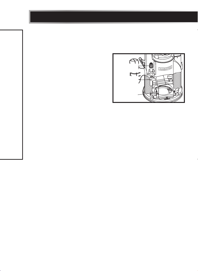
SETTING THE CUTTING DEPTH FOR PLUNGE BASE ROUTING
The cutting depth can be adjusted in two ways: by depressing the handles, or by
turning the depth stop on the plunge base.
Adjustment by depressing the handles
(see fig 10)
1. Unplug the router.
2. Place the plunge base on a flat surface
or on the workpiece.
3. Loosen the locking arm.
4. Loosen the knob on the adjustment bar.
5. Depress the handles to the desired
depth.
6. Tighten the locking arm.
7. Tighten the knob on the adjustment bar.
Adjustment using the depth stop
1. Unplug the router.
2. Unlock the locking arm.
ASSEMBLY INSTRUCTIONS
3. Loosen the knob on the adjustment bar.
4. Set the plunge adjustment knob to the desired setting by turning it clockwise
or counter-clockwise to raise or lower the depth stop.
5. Tighten the locking arm.
6. Tighten the knob on the adjustment bar.
g 10
Adjustment
bar
Adjustment
bar knob
Depth stop
Page 19
19
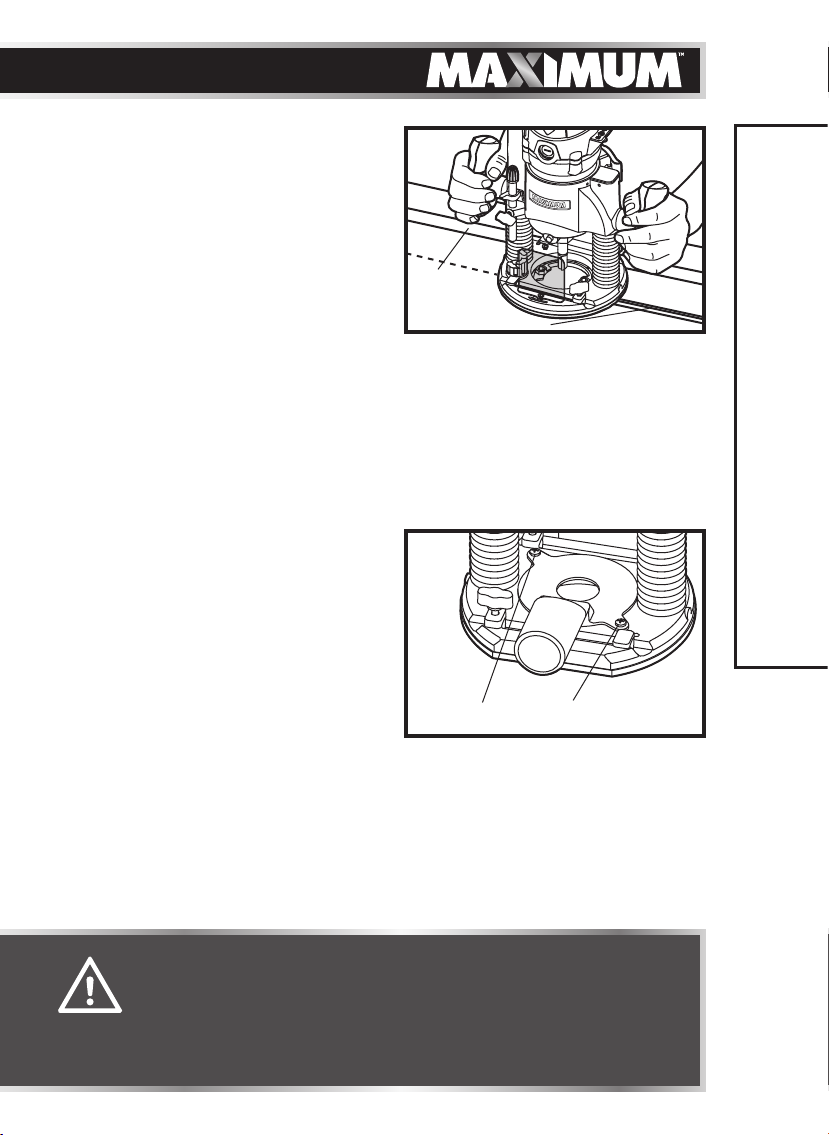
PLUNGING ACTION (g 11)
The plunge base feature simplifies depth
adjustments and allows the cutter bit to
be accurately lowered into the workpiece
for precise set-ups.
1. To lower the cutter bit, release the
plunge-lock lever by moving it “UP” to
the unlock position.
2. Apply an even, downward pressure on
the plunge action until the cutter bit
reaches the desired depth, then move the plunge-lock lever “DOWN” to the
locked position.
3. To raise the bit and the plunge action, unlock the plunge-lock lever and the
cutter bit and the plunge action will automatically retract from the workpiece
and return to the raised position.
Always have the plunge action in the raised position and locked when the bit is
not cutting in the workpiece.
DUST COLLECTION WITH VACUUM
PORT (g 12)
The vacuum port is sized to accept a 1
1/4" vac hose adapter (sold separately).
Unplug the router. To attach the vacuum
port onto the plunge base, position and
secure it to the back of the base with the
two screws (included), as shown in fig 12.
The vacuum port can also be installed
with the hose outlet facing the front of
the plunge base by removing the chip shield and attaching the adapter at the
front of the base.
g 11
Edge
Guide
Slot Cutting
g 12
2 Screws Included
ASSEMBLY INSTRUCTIONS
ASSEMBLING THE EDGE GUIDE
To assemble the edge guide onto the fixed or plunge base, simply insert the
edge-guide rods into the edge guide mounting slots, adjust to the desired
position, and lock down using the edge-guide locking knobs.
WARNING!
• Always turn the router motor off and unplug the router from
the power source before making any adjustments, installing
accessories or performing maintenance. Failure to turn the motor
off and unplug the router could result in accidental starting,
which can cause serious personal injury.
Page 20
20
model no. 054-6810-8 | contact us 1-888-670-6682
OPERATING INSTRUCTIONS
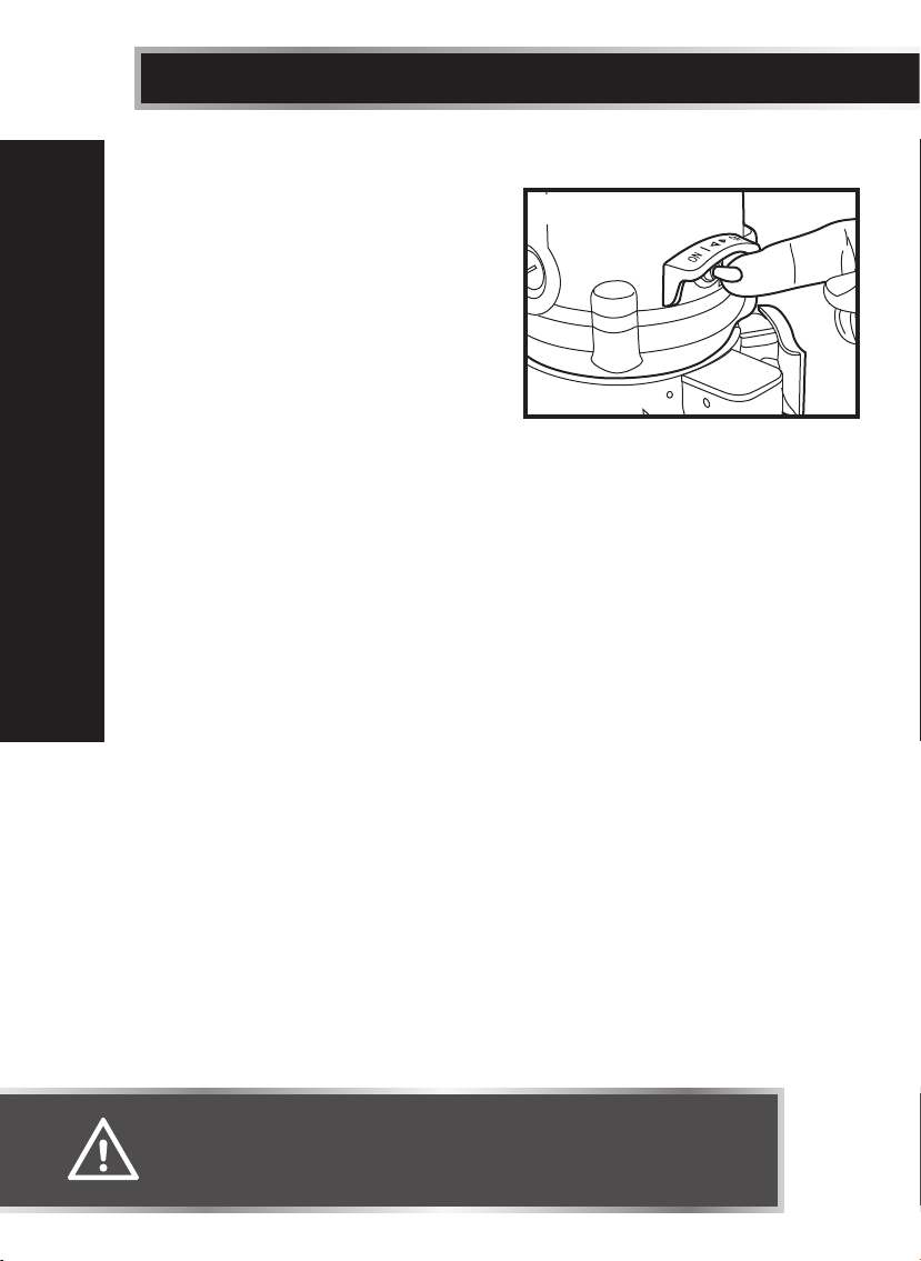
TO TURN THE ROUTER ON AND OFF
(g 13)
The router motor is turned “ON” and
“OFF” with using the toggle switch
located on the top cap of the motor
housing. The left side of the toggle
switch hood (when facing the operator)
is marked “I” for “ON”, and the right side
(when facing the operator) is marked “O”
for “OFF”.
To turn the motor “ON”, push the toggle switch to the left side, marked “I” for
“ON”.
To turn the motor “OFF”, push the toggle switch to the right side marked “O” for
“OFF”.
Always hold the router and cutter bit away from the workpiece when turning the
toggle switch “on”.
Only allow the router and cutter bit to come into contact with the workpiece
after the router has reached full speed. Only remove the router and cutter bit
from the workpiece after turning the router motor “off” and allowing the cutter
bit to come to a complete stop. Operating in this manner will increase the life of
OPERATING INSTRUCTIONS
the toggle switch and motor, and will increase the quality of the work.
g 13
WARNING!
• Always make sure that the switch is in the “OFF” position before
plugging it into a power source.
Page 21
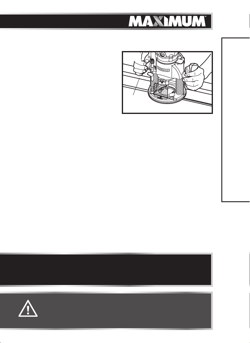
STARTING THE CUT
Much of routing is a trial-and-error
process of making various adjustments,
followed by test cuts as you become
familiar with all of your router’s
operational abilities. To avoid ruining
good material, make your test cuts on
scrap materials.
For ease of operation and to maintain
proper control, your router has two
handles, one on each side of the router
base. When operating the router, always
hold it firmly with both hands (Fig. 14).
DEEP CUTS
The proper cutting depth for each pass is always determined by the material, the
cutter bit size and type, and the power of the motor.
Always make several progressively deeper cuts: start at one depth and then
make several passes, each time increasing the cutting depth, until the desired
depth is reached.
Making a cut that is too deep will stress the router motor and the cutter bit, and
it may burn the workpiece and dull the cutter bit. It could also “grab” too much
of the workpiece, causing you to lose of control of the router, which may result in
a serious accident.
To be certain that your depth settings are correct, always make test cuts in scrap
material similar to your workpiece before beginning the final cutting operation.
Remember, knowing the right depth for each cut comes with routing experience.
g 14
Edge
Guide
Edge with plunge base
21
OPERATING INSTRUCTIONS
NOTICE: Making test cuts is essential with most routing applications. Even
with careful set-ups, you won’t know exactly how the cut will go until you try
it out. A test cut will give a feel for the set-up, the router’s speed, the depth
of cut, and how the cutter bit reacts to the workpiece.
WARNING!
• Before operating the router, follow all safety instructions in this
manual. Failure to do so could result in serious personal injury.
• Always be alert and watch what you are doing. Never operate the
router when you are fatigued or otherwise impaired.
Page 22
22
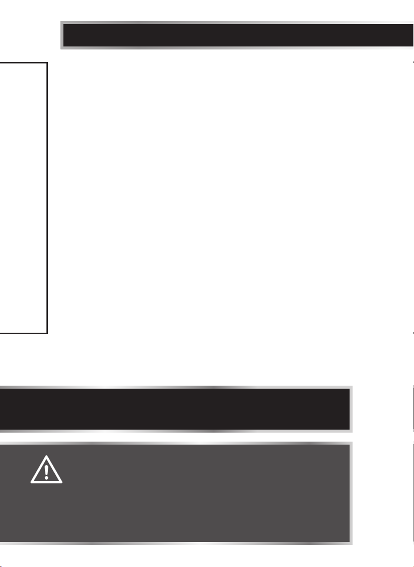
EDGE ROUTING WITH THE FIXED/PLUNGE BASE (g 14)
1. Unplug the router.
2. Set the cutting depth and place the router on the edge of workpiece, making
3. Clamp an edge guide (board or metal straightedge) onto the workpiece to
4. Plug in the router.
5. Turn the router “On”, and allow the motor to build to the full speed selected.
6. To begin your cut, gradually feed the cutter bit into the edge of the
7. When the cut is complete, turn the motor “Off” and allow cutter bit come to a
8. Unplug the router from the power source, place the router upside down on
OPERATING INSTRUCTIONS
model no. 054-6810-8 | contact us 1-888-670-6682
sure that the cutter does not contact the workpiece.
help guide the router base.
workpiece.
complete stop before removing it from the workpiece.
the worktable, and inspect the finished cut in the workpiece.
NOTICE: Making test cuts in scrap material that is similar to your workpiece
is essential. Learning how the router’s speed, depth-of-cut and cutter bit will
react in the workpiece will help you produce quality cuts.
WARNING!
• Always securely clamp your workpiece and keep a firm grip on
the router base with both hands at all times. Failure to do so could
result in loss of control, causing possibly serious personal injury.
If using a router table, large cutter bits should be used for edging
only.
• Removing the cutter bit from the workpiece while it is still
rotating could damage the workpiece and result in loss of control,
causing serious personal injury.
Page 23
23
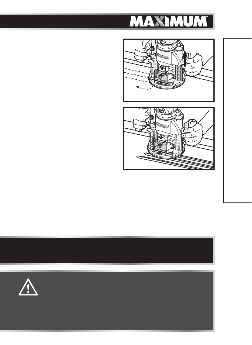
INTERNAL ROUTING WITH THE
PLUNGE BASE (gs 15 and 15a)
1. Set the cutting depth and lock the
plunge action in the raised (Up)
position. Turn the motor “On” and
allow the motor build up to its full
speed (see fig 15).
2. To begin your cut, unlock the plunge
lock lever and gently lower the plunge
action into the workpiece (see fig 15a).
3. When the desired depth-of-cut is
achieved, lock the plunge lock lever
(Down) and proceed to make your cut
(fig 15a).
4. When the cut is completed, turn the
motor “off” and allow the cutter bit
to come to a complete stop before
removing it from the workpiece.
5. When the cutter bit comes to a complete stop, unlock the plunge lock lever
(Up) and the plunge action will automatically retract the cutter bit from the
workpiece.
6. Unplug the router from the power source, place the router on the worktable,
and inspect the finished cut in the workpiece.
g 15
Feed Direction
g 15a
Plunge
Down
Cutting
Plunge up
set up
Edge
Guide
OPERATING INSTRUCTIONS
NOTICE: Making test cuts in scrap material that is similar to your workpiece
is essential. Learning how the router’s speed, depth-of-cut and cutter bit will
react in the workpiece will help you produce quality cuts.
WARNING!
• Always securely clamp your workpiece and keep a firm grip on
the router base with both hands at all times. Failure to do so could
result in loss of control, causing possibly serious personal injury.
• Removing the cutter bit from the workpiece while it is still
rotating could damage the workpiece and result in loss of control,
causing serious personal injury.
Page 24
24
model no. 054-6810-8 | contact us 1-888-670-6682
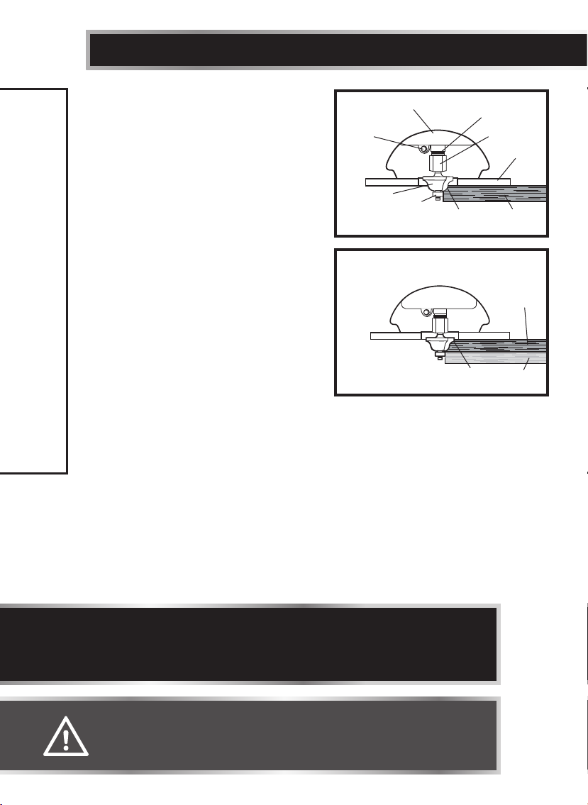
EDGING WITH A PILOT BIT
(gs 16 and 16a)
The arbor-type bits with pilots are
excellent for edge shaping any workpiece
edge that is either straight, or has a curve
equal to or greater than the radius of the
bit to be used.
The pilot prevents the bit from making
an excessively deep cut, and holding the
pilot firmly in contact with the workpiece
edge throughout prevents the cut from
becoming too shallow.
Top Edge Shaping
Whenever the workpiece thickness,
together with the desired depth of cut
(as adjusted by router depth setting) are
such that only the top part of the edge is
to be shaped (leaving at least a 1/16 in.
thick uncut portion at the bottom), the
pilot can ride against the uncut portion,
which serves to guide it (fig 16).
OPERATING INSTRUCTIONS
Whole Edge Shaping
If the workpiece is too thin or if the bit is set so low that there will be no uncut
edge against which to ride the pilot, you will be shaping the whole edge of the
workpiece, and an extra board must be placed under the workpiece to act as
a guide (see fig 16a). This “guide” board must have exactly the same contour straight or curved - as the workpiece edge. If it is positioned so that its edge is
flush with the workpiece edge, the bit will make a full cut (cutting in as far as
the bit radius). On the other hand, if the guide is positioned so that it extends
beyond the edge of the workpiece, the bit will make less than a full cut - which
will alter the shape of the finished edge.
g 16
Spindle
Lock
Cutter-bit
TOP EDGE
SHAPING
Motor Housing
Pilot
g 16a
WHOLE EDGE
SHAPING
Top Edge of
Workpiece
Whole Edge of
Workpiece
Spindle
Collet/Nut
Fixed Base
Workpiece
Workpiece
Guide
Board
NOTICE: The size (diameter) of the pilot that is used determines the maximum
width that can be cut with the pilot against the workpiece edge (a small pilot
exposes all of the bit; a large pilot reduces this amount by 1/16 in.). Any of the
piloted cutter bits can be used without a pilot for edge shaping with guides.
WARNING!
• Always securely clamp your workpiece and keep a firm grip on
the router base with both hands at all times. Failure to do so could
result in loss of control, causing possible serious personal injury.
Page 25
25
FEEDING THE
ROUTER (g 17)
The secrets to professionallooking routing are careful
set-up for the cut, proper
depth-of-cut selection, knowing
how the cutting bit reacts in
the workpiece, and the rate and
direction of feed of the router.
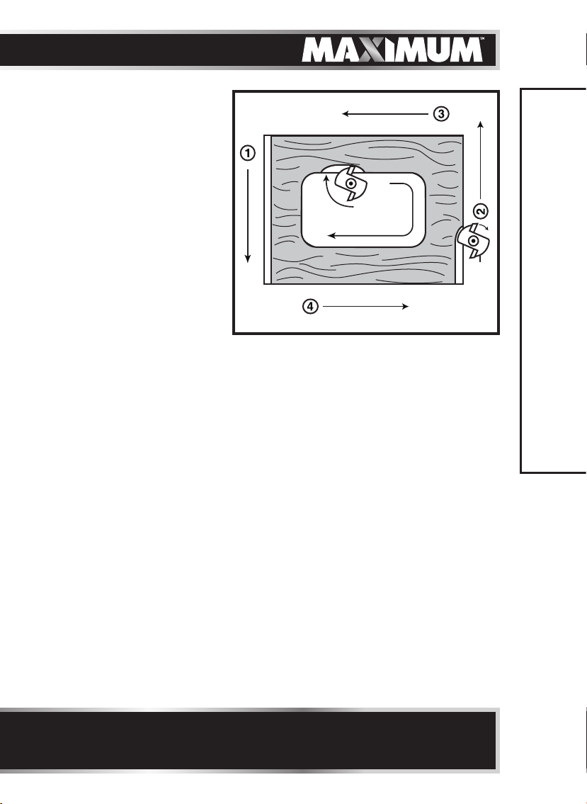
DIRECTION OF FEED:
g 17
ROUTER END
GRAINS FIRST
ROUTER FEED
DIRECTION
BIT
ROTATION
ROUTER FEED
DIRECTION
ROUTER FEED
DIRECTION
EXTERNAL CUTS
The router motor and cutting
bit rotate clockwise. This
requires the feed of the cutting
bit to be from left to right (see
fig 17). Feeding the bit from left
to right will cause the bit to pull the router towards (up against) the workpiece.
If the router is fed in the opposite direction (right to left), the rotating force of
the cutting bit will tend to throw the bit away from the workpiece, making it hard
to control. This is called “Climb-Cutting:” cutting in the opposite direction of the
proper feed direction. “Climb Cutting” increases the chance of losing control,
resulting in possible personal injury. When “Climb Cutting” is required (backing
around a corner, for example), exercise extreme caution to maintain control of
the router.
ROUTER FEED
DIRECTION
KICKBACK
Because of the high speed of the cutting bit during a proper feeding operation
(left to right), there is very little kickback under normal conditions. However, if
the cutting bit strikes a knot, an area of hard grain in the workpiece, or a foreign
object, the normal cutting action could be affected and cause “Kickback.” This
Kickback may cause damage to your workpiece, and could cause you to lose
control of the router, possibly causing serious personal injury. Kickback is always
counterclockwise: the opposite direction of the clockwise cutting bit rotation.
To guard against and help prevent Kickback, Always inspect the workpiece for
knots, hard grain, and foreign objects that could cause a kickback problem and
plan the set-up and direction of feed so that the router is always moving, and
keep the sharp edges of the cutting bit continuously biting straight into new
(uncut) wood (workpiece).
OPERATING INSTRUCTIONS
NOTICE: When the router is installed in a router table, the bit rotation will
be counterclockwise and the workpiece must be fed from right to left on the
table.
Page 26
26
model no. 054-6810-8 | contact us 1-888-670-6682
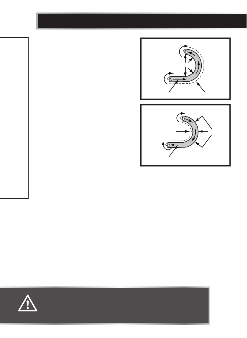
DIRECTION OF FEED - INTERNAL
CUTS (gs 18a and 18b)
When making an internal cut, such as a
groove, dado, or slot, the edge guide,
straight edge, or board guide must
always be positioned on the right-hand
side of the router as you make the cut
(fig 18a).
When the guide is positioned on the
right hand side of the router, the router
travel should be from left to right and
“counterclockwise” around curves (see
fig 18a). This counterclockwise action
around the curve could cause “Climb
cutting.” Always be alert and exercise
extreme caution to maintain control of
the router when making this type of cut
around curves.
When the guide is positioned as shown in
fig 18b, the router travel should be from
left to right and clockwise around curves.
OPERATING INSTRUCTIONS
If there is a choice, the set-up in fig 18a is easier to use, but there is the
possibility of “Climb Cutting” around curves. In either case, fig 18a or fig 18b, the
sideways thrust of the router cutting is always against the guide, as is proper.
g 18a
Bit
rotation
Rotation feed direction
g 18b
Bit rotation
Bit
rotation
Rotation feed direction
Guide outside
Bit rotation
Thrust
Guide inside
Guide
Guide
Thrust
WARNING!
• Always securely clamp the workpiece in place, and keep a firm
grip on the router base with both hands at all times. Failure to do
so could result in loss of control, causing possibly serious personal
injury.
Page 27
27
RATE OF FEED (gs 19a and 19b)
The proper rate of feed depends on
several factors: the hardness and moisture
content of the workpiece, the depth of
cut, and the cutting diameter of the bit.
When cutting shallow grooves in soft
woods, such as pine, you may use a faster
rate of feed. When making deep cuts in
hardwoods, such as oak, you should use a
slower rate of feed.
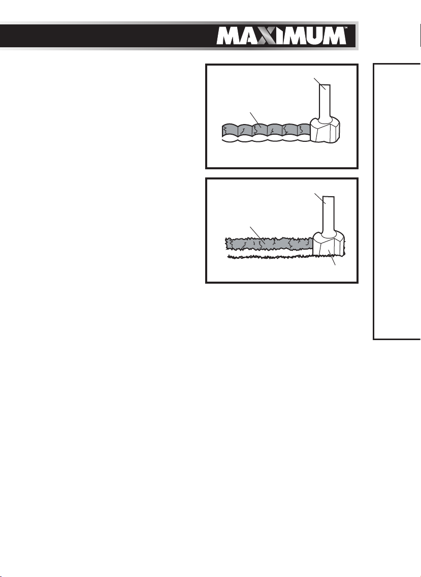
FEEDING TOO RAPIDLY (g 19a)
Clean and smooth finished cuts can
only be achieved when the cutting bit is
rotating at a relatively high speed, taking
very small bites, and producing tiny,
clean-cut chips.
Forcing the feed of the cutting bit
forward too rapidly slows the revolution
of the cutting bit, and the bit takes larger
bites as it rotates. Larger bites mean
larger chips and a rough finish. This forcing action can also cause the router
motor to overheat.
Under extreme force-feeding conditions, the revolutions can become so slow
and the bites become so large that chips are only partially cut off, causing
splintering and gouging of the workpiece.
The router will make clean, smooth cuts if it is allowed to run freely without the
overload of forced feeding. You can detect forced feeding by the sound of the
motor. Its usual high-pitched whine will sound lower and stronger as it loses
speed. Holding the router against the workpiece will also be more difficult to do.
g 19a
Cut
TOO FAST
g 19b
Cut
TOO SLOW
Bit Shank
Cutter
Bit Shank
Cutter
OPERATING INSTRUCTIONS
FEEDING TOO SLOWLY (g 19b)
When you feed the cutting bit too slowly, the rotating cutting bit does not cut
into new wood rapidly enough to take a bite. Instead, it scrapes away sawdustlike particles. This scraping produces heat, which can glaze, burn, and mar the
cut in the workpiece and, in extreme cases, overheat the cutting bit.
When the cutting bit is scraping instead of cutting, the router is more difficult to
control as you feed it.
With almost no load on the motor, the cutting bit has a tendency to bounce
off the sides of the cut in the workpiece, producing a cut with a rippled finish
instead of clean, straight sides.
Page 28

model no. 054-6810-8 | contact us 1-888-670-6682
28
MAINTENANCE
Before cleaning or performing any maintenance, verify that the router has been
disconnected from the power supply. Keep all ventilation openings clean. Avoid
using solvents when cleaning plastic parts. Most plastics are susceptible to
damage from various types of commercial solvents. Use a clean cloth to remove
dirt, oil, and grease.
MAINTENANCE
WARNING!
• Always turn the router motor off and unplug router from
the power source before making any adjustments, installing
accessories or preforming maintenance. Failure to turn the motor
off and unplug the router could result in accidental starting, which
can cause serious personal injury.
• Do not let brake fluids, gasoline, petroleum-based products,
penetrating oil, etc., come into contact with plastic parts. They
contain chemicals that can damage, weaken, or destroy plastic.
• To ensure safety and reliability, all repairs should be performed by
a qualified service technician.
• If the supply cord is damaged, it must be replaced by a specially
prepared cord available through the service organization.
Page 29

TROUBLESHOOTING
Problem Possible causes Solution
The router does
not work
The router is not
plugged into an
electrical outlet.
Insert the plug from the router
power cord into an electrical
outlet.
29
TROUBLESHOOTING
Page 30
30
PART LIST
model no. 054-6810-8 | contact us 1-888-670-6682
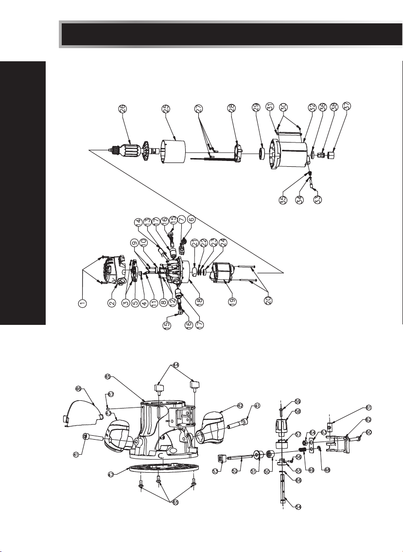
EXPLODED VIEW
Motor Unit
Fixed Unit
Page 31
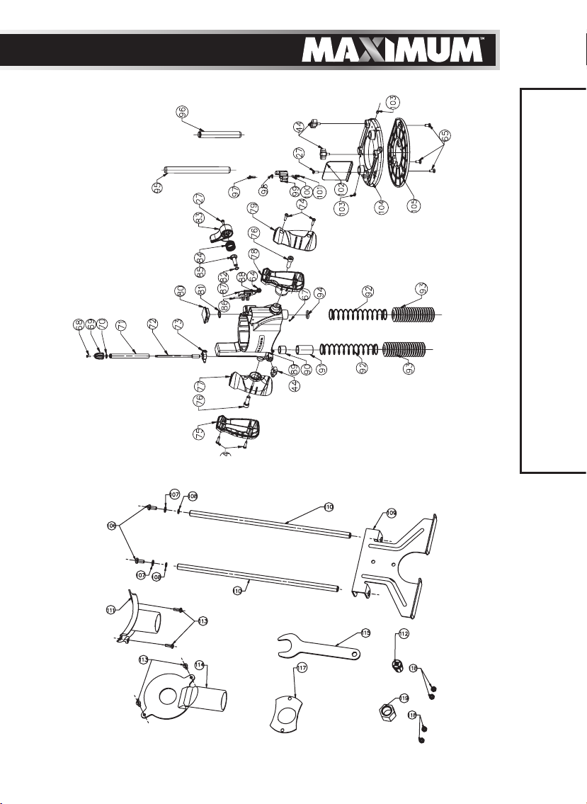
Plunge Base
Router Accessory
31
PART LIST
Page 32
32
PART LIST
model no. 054-6810-8 | contact us 1-888-670-6682
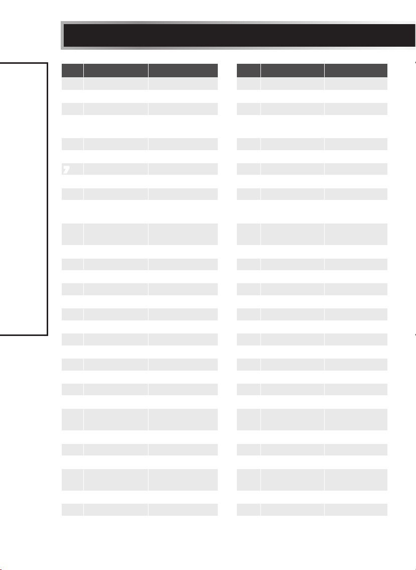
No. Part No. Description No. Part No. Description
1 5610220000 Screw 32 3420356000 Housing
2 3320366000 Rear Cover 33 3550592000 Spindle Lock
3 5610017000 Screw 34 5660005000 “E’’ Ring
4 3121518000 Transparent
Cap
5 4900247000 PCB Plate 36 5630179000 Nut
6 3122851000 Seal Ring 37 5630187000 Collet Nut
7 4870073000 Switch 38 3550721000 Collet
8 5610059000 Screw 41 5620024000 Screw
9 5610106000 Tapping Screw 42 3320363000 Right Handle
10 3122798000 Cord
Anchorage
11 4540017000 Power Indicator
Light
12 5620017000 Screw 45 3420471000 Mounting
13 4810002188 Power Cord 46 3121637000 Chip Shield
14 3121050000 Cord Guard 47 3122840000 Base Plate
15 3120537000 Brush Cap 48 5660003000 E Ring
16 4960019000 Carbon Brush 49 3660167000 Spring
17 2800005000 Brush Holder 50 3520147000 Lock Gear
18 3121494000 Middle Housing 51 3520141000 Gear
19 2740118000 Stator 52 3550579000 Gear Shaft
20 5610050000 Screw 53 3121648000 Button
21 3123926000 Bearing Holder 54 3550613000 Shaft
22 3121049000 Rubber Spring 55 3550615000 Worm
23 3700249000 Washer 56 5620033000 Screw
24 5700008000 Bearing 57 3121647000 Indicator Ring
25 3121495000 Fan Baffle 58 3121646000 Adjusting
26 2750184000 Rotor 59 5620041000 Screw
27 5620040000 Screw 60 5620332000 Screw
28 2820887000 LED 61 3550596000 Lock Pin
29 5700056000 Bearing 62 3420395000 Clamping
30 5620062000 Screw 63 3700848000 Plate
31 3520227000 Gear Rack 64 5630015000 Lock Nut
35 3660174000 Stop Spring
43 3320368000 Left Handle
44 3400189000 Lock Bolt
Knob
Lever
Page 33
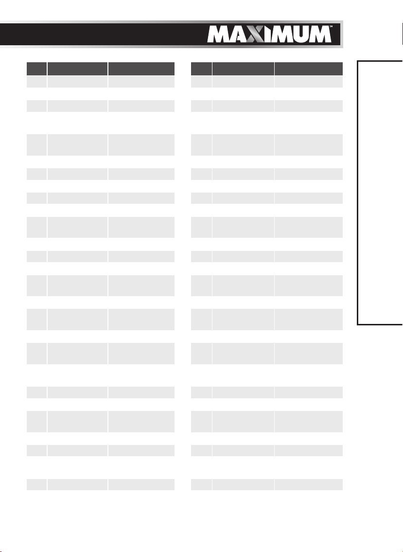
No. Part No. Description No. Part No. Description
65 5620049000 Screw 92 3660166000 Spring
66 5650172000 Washer 93 3123581000 Bellows Seal
67 5670040000 Located Pin 94 5690120000 “O’’Ring
68 5620032000 Screw 95 3550576000 Long Plunge
Rod
69 3120200000 Depth
Adjusting Cap
70 5690002000 “O’’ Ring 97 5620103000 Screw
71 3550791000 Depth Stop Bar 98 5650007000 Gasket
72 3550083000 Adjusting Pole 99 3420387000 Turn Table
73 3121634000 Depth Indicator 100 5700046000 Steel Ball
74 5610042000 Screw 101 3660030000 Spring
75 3320369000 Left Handle
Cover
76 5620023000 Screw 103 5670158000 Spring Pin
77 3320365000 Left Handle 104 3420370000 Mounting
78 3320364000 Right Handle 105 3122841000 Base Plate
79 3320367000 Right Handle
Cover
80 3121639000 Cover 107 5650015000 Spring Washer
81 5660018000 Circlips of
Shaft
82 3700078000 Spring Washer 109 3703591000 Parallel Guide
83 3420398000 Plunge Lock
Lever
84 3660254000 Torsion Spring 111 3122784000 Vacuum
85 5640045000 Bolt 112 3550595000 Collet
86 5670039000 Pin 113 5620040000 Screw
87 3420390000 Clamping Lever 114 3121599000 Vacuum
88 3550577000 Mitre Lock Bolt 115 3700807000 Wrench
89 3420470000 Plunge Frame 117 3700806000 Guide Bush
90 5700055000 Oil Impreging
Bearing
91 3520138000 Bush 119 5630187000 Collet Nut
96 3550575000 Plunge Rod
102 3121583000 Chip Shield
106 5620050000 Screw
108 5650013000 Plain Washer
110 3550683000 Guiding Rod
Adapter
Adapter
118 5630003000 Nut
33
PART LIST
If the problem remains unsolved after performing the checks described above,
call the toll-free helpline at 1-800-689-9928.
Page 34

34
WARRANTY
model no. 054-6810-8 | contact us 1-888-670-6682
5-YEAR LIMITED WARRANTY
This MAXIMUM product is guaranteed for a period of 5
years from the date of original retail purchase against
defects in workmanship and materials only and is
subject to the following components:
a) Component A: The carrying case is guaranteed for
a period of 1-year from the date of original retail
purchase against defects in workmanship and
materials.
b) Component B: Accessories, including drill bits and
saw blades, do not carry a warranty.
Subject to the conditions and limitations described
below, this product, if returned to us with proof of purchase within the stated
warranty period and if covered under this warranty, will be repaired or replaced
(with the same model, or one of equal value or specification), at the sole discretion
of the Maximum Canada authorised repair centre (“Service Provider”). We will bear
the cost of any repair or replacement and any costs of labour relating thereto.
These warranties are subject to the following conditions and limitations:*
a) a bill of sale verifying the purchase and purchase date must be provided;
b) defects in workmanship and material to be assessed and determined by the
Service Provider;
c) this warranty will not apply to any product or part thereof which is worn or
broken or which has become inoperative due to abuse, misuse, accidental
damage, neglect or lack of proper installation, operation or maintenance
(as outlined in the applicable owner’s manual or operating instructions);
d) this warranty does not apply to normal wear and tear or to expendable parts
or accessories (including drill bits and saw blades) that may be supplied with
the product that by their nature have a limited life span and are expected to
become inoperative or unusable after a reasonable period of use;
e) this warranty will not apply to routine maintenance and consumable items
such as, but not limited to, fuel, lubricants, vacuum bags, blades, belts,
sandpaper, bits, fluids, rubber o-rings, tune-ups or adjustments;
f) this warranty excludes the following components that may accompany your
product:
(1) the carrying case, which is only for a period of 1-year from the date of
original retail purchase against defects in workmanship and materials.
(2) accessories, including drill bits and saw blades, which do not carry a
warranty of any kind.
g) this warranty will not apply where damage is caused by repairs made or
attempted by others (i.e. persons not authorized by the manufacturer), and
any such unauthorized repairs or attempted repairs shall void this warranty
in its entirety;
Page 35

h) this warranty will not apply to any parts other than original parts, except to
the extent that the retailer or manufacturer or persons authorized by either
of them have repaired or replaced them;
i) this warranty will not apply to any product that was sold to the original
purchaser as a reconditioned or refurbished product (unless otherwise
specified in writing);
j) this warranty will not apply to any product or part thereof if any part from
another manufacturer is installed therein or any repairs or alterations have
been made or attempted by unauthorized persons;
k) this warranty will not apply to normal deterioration of the exterior finish,
such as, but not limited to, scratches, dents, paint chips, or to any corrosion
or discolouring by heat, abrasive and chemical cleaners; and
l) this warranty will not apply to component parts sold by and identified as
the product of another company, which shall be covered under that product
manufacturer’s warranty, if any;
m) any products replaced by the retailer in attempt to fulfill warranty
obligations is subject to the original product warranty conditions and
related time period as initiated by the original date of purchase; if product
is purchased in Quebec, the warranty term will be extended for a period
equal to the time during which the Quebec retailer possesses the product in
attempt to fulfill warranty obligations; replaced product will not default to
new product warranty conditions; and
n) the retailer and manufacturer’s sole obligation and the purchaser’s sole
remedy under this warranty shall be as set out herein. The warranties
contained herein are not transferable and are given only to the purchaser.
FURTHER, THE WARRANTIES SET OUT HEREIN ARE IN LIEU OF ALL
OTHER WARRANTIES OR CONDITIONS, WHETHER EXPRESS, IMPLIED OR
STATUTORY (INCLUDING SUCH AS ARISE UNDER THE SALE OF GOODS
ACT OR THE INTERNATIONAL SALE OF GOODS ACT), ARISING OUT OF A
COURSE OF DEALING OR USAGE OF TRADE OR OTHERWISE, INCLUDING,
SUBJECT TO APPLICABLE LAW, ANY IMPLIED WARRANTIES OR
CONDITIONS OF MERCHANTABILITY, MERCHANTABLE QUALITY, FITNESS
OR ADEQUACY FOR A PARTICULAR PURPOSE OR USE, AND ALL OTHER
SUCH WARRANTIES ARE EXPRESSLY DISCLAIMED BY THE RETAILER AND
MANUFACTURER.
35
WARRANTY
Additional Limitations
This warranty applies only to the original purchaser and may not be transferred.
This warranty applies for a period of 5 years from the date of original retail
purchase, as indicated on the bill of sale.
Neither the retailer, Maximum Canada, nor the manufacturer shall be liable for
any other expense, loss or damage, including, without limitation, any indirect,
incidental, consequential or exemplary damages arising in connection with the
sale, use or inability to use this product.
Page 36

36
model no. 054-6810-8 | contact us 1-888-670-6682
Under no circumstances shall the retailer, Maximum Canada, or manufacturer
be liable to the purchaser for any claim for (a) indirect, special, punitive,
incidental, exemplary, or consequential damages, (b) compensation for loss of
profits, anticipated revenue, savings or goodwill, or other economic loss of the
purchaser, (c) exemplary, aggravated or punitive damages howsoever incurred,
(d) contribution or set-off in respect of any claims against the purchaser, (e)
any damages whatsoever relating to third party products or services or the
purchaser’s materials, or (f) any damages whatsoever relating to interruption,
delays, errors or omissions; in each case under any theory of law or equity,
arising out of or in any way related to this warranty, even if advised of the
possibility thereof. Notwithstanding any provision herein or entitlement of
the purchaser at law, in equity or otherwise, in no event shall the liability of
the retailer or manufacturer under this warranty, whether in contract, tort,
product liability or otherwise, exceed, in the aggregate, the amount paid by the
purchaser to the retailer for the product to which this warranty applies.
*Notice to Consumer
This warranty gives you specific legal rights, and you may have other rights, which
may vary from province to province. The provisions contained in this warranty are
not intended to limit, modify, take away from, disclaim or exclude any statutory
warranties set forth in any applicable provincial or federal legislation.
In addition to the 5-Year Limited Warranty, this MAXIMUM product is covered by our:
WARRANTY
Maximum Canada will maintain this product and replace critical parts which
have worn beyond reasonable use through normal use of such product, any time
during the first year after purchase.
The following are excluded from this 1-Year Repair Warranty:
a) missing or damaged parts or components that are a result of abuse or
b) any wear and tear to non-critical parts or accessories that do not affect the
If you are not completely satisfied with the performance of your MAXIMUM
product for any reason, you can return it within 90 days from the date of
purchase with proof of purchase for exchange or a full refund.
Made in China
Imported by
MAXIMUM Canada Toronto, Canada M4S 2B8
1-Year Repair Warranty
misuse;
core function of the product.
90-Day Satisfaction Guarantee
 Loading...