

Page 1

Model No. 054-4297-2
IMPORTANT:
Please read this manual carefully before
using this product, and save it for reference.
INSTRUCTION
MANUAL
Page 2

Page 3

TABLE OF CONTENTS
Technical Specifications 4
Safety Guidelines 5
Key Parts Diagram 11
Important Information 12
Assembly Instructions 13
Operating Instructions 16
Maintenance 18
Troubleshooting 20
Parts List 21
Warranty 23
3
TABLE OF CONTENTS
NOTE: If any parts are missing or damaged, or if you
have any questions, please call our toll-free helpline at
1-888-670-6682.
SAVE THESE INSTRUCTIONS
• This manual contains important safety and
operating instructions. Read all instructions
and follow them with use of this product.
Page 4

4
model no. 054-4297-2 | contact us 1-888-670-6682
TECHNICAL SPECIFICATIONS
Rated Voltage 120V~, 60 Hz
Rated Power Input 13A
Rated Speed 10,500 RPM*
Compatible wheel sizes 5" (125 mm) & 4 1/2" (115 mm)
Wheel guard sizes 5" (125 mm) & 4 1/2" (115 mm)
Arbour Size 5/8" (16 mm)
Weight 6 lb 5 oz (2.87 kg)
Supply cord 10' (3 m) SJOW
*Tool’s rated speed is 10,500 RPM; using constant speed control (CSC) the
optimized speed is 9000 RPMs.
TECHNICAL SPECIFICATIONS
Page 5
RULES FOR SAFE OPERATION
KNOW YOUR TOOL
To operate this angle grinder, carefully read this instruction manual and all labels
affixed to the tool. Keep this manual available for future reference.
IMPORTANT
This angle grinder should only be serviced by a qualified service technician. For
more information, call the toll free helpline at 1-888-670-6682.
READ ALL INSTRUCTIONS CAREFULLY
SAVE THESE INSTRUCTIONS
GENERAL POWER TOOL SAFETY WARNINGS
WARNING!
Read all safety warnings and instructions. Failure to follow the warnings
and instructions may result in electric shock, fire and/or serious injury.
SAVE ALL WARNINGS AND INSTRUCTIONS FOR FUTURE
REFERENCE.
The term “power tool” in the warnings refers to your mains-operated (corded)
power tool or battery-operated (cordless) power tool.
WORK AREA SAFETY
• Keep work area clean and well lit. Cluttered or dark areas invite accidents.
• Do not operate power tools in explosive atmospheres, such as in the presence
of flammable liquids, gases or dust. Power tools create sparks which may
ignite the dust or fumes.
• Keep children and bystanders away while operating a power tool. Distractions
can cause you to lose control.
5
SAFETY GUIDELINES
ELECTRICAL SAFETY
• Power tool plugs must match the outlet. Never modify the plug in any way. Do
not use any adapter plugs with earthed (grounded) power tools. Unmodified
plugs and matching outlets will reduce risk of electric shock.
• Avoid body contact with earthed or grounded surfaces, such as pipes,
radiators, ranges and refrigerators. There is an increased risk of electric shock
if your body is earthed or grounded.
• Do not expose power tools to rain or wet conditions. Water entering a power
tool will increase the risk of electric shock.
• Do not abuse the cord. Never use the cord for carrying, pulling or unplugging
the power tool. Keep cord away from heat, oil, sharp edges or moving parts.
Page 6

6
model no. 054-4297-2 | contact us 1-888-670-6682
Damaged or entangled cords increase the risk of electric shock.
• When operating a power tool outdoors, use an extension cord suitable for
outdoor use. Use of a cord suitable for outdoor use reduces the risk of electric
shock.
• If operating a power tool in a damp location is unavoidable, use a ground-fault
circuit interrupter (GFCI) protected supply. Use of a GFCI reduces the risk of
electric shock.
PERSONAL SAFETY
• Stay alert, watch what you are doing and use common sense when operating a
power tool. Do not use a power tool while you are tired or under the influence
of drugs, alcohol or medication. A moment of inattention while operating
power tools may result in serious personal injury.
• Use personal protective equipment. Always wear eye protection. Protective
equipment such as dust mask, non-skid safety shoes, hard hat, or hearing
protection used for appropriate conditions will reduce personal injuries.
• Prevent unintentional starting. Ensure the switch is in the off-position before
connecting to power source and/or battery pack, picking up or carrying the
tool. Carrying power tools with your finger on the switch or energising power
tools that have the switch on invites accidents.
• Remove any adjusting key or wrench before turning the power tool on. A
SAFETY GUIDELINES
wrench or a key left attached to a rotating part of the power tool may result in
personal injury.
• Do not overreach. Keep proper footing and balance at all times. This enables
better control of the power tool in unexpected situations.
• Dress properly. Do not wear loose clothing or jewellery. Keep your hair,
clothing and gloves away from moving parts. Loose clothes, jewellery or long
hair can be caught in moving parts.
• If devices are provided for the connection of dust extraction and collection
facilities, ensure that these are connected and properly used. Use of these
devices can reduce dust-related hazards.
POWER TOOL USE AND CARE
• Do not force the power tool. Use the correct power tool for your application.
The correct power tool will do the job better and more safely at the rate for
which it was designed.
• Do not use the power tool if the switch does not turn it on and off. Any power
tool that cannot be controlled with the switch is dangerous and must be
repaired.
• Disconnect the plug from the power source and/or the battery pack from the
power tool before making any adjustments, changing accessories, or storing
power tools. Such preventive safety measures reduce the risk of starting the
power tool accidentally.
Page 7

• Store idle power tools out of the reach of children and do not allow persons
unfamiliar with the power tool or these instructions to operate the power tool.
Power tools are dangerous in the hands of untrained users.
• Maintain power tools. Check for misalignment or binding of moving parts,
breakage of parts and any other condition that may affect the power tool’s
operation. If damaged, have the power tool repaired before use. Many
accidents are caused by poorly maintained power tools.
• Keep cutting tools sharp and clean. Properly maintained cutting tools with
sharp cutting edges are less likely to bind and are easier to control.
• Use the power tool, accessories, tool bits, etc. in accordance with these
instructions, taking into account the working conditions and the work to be
performed. Use of the power tool for operations different from those intended
could result in a hazardous situation.
SERVICE
• Have your power tool serviced by a qualified repair person using only
identical replacement parts. This will ensure that the safety of the power tool
is maintained.
SAFETY GUIDELINES FOR ANGLE GRINDER
• This power tool is intended to function as a grinder. Read all safety warnings,
instructions, illustrations and specifications provided with this power tool.
Failure to follow all instructions listed below may result in electric shock, fire
and/or serious injury.
• Operations such as sanding, wire brushing, polishing or cutting-off are not
recommended to be performed with this power tool. Operations for which the
power tool was not designed may create a hazard and cause personal injury.
• Do not use accessories that are not specifically designed and recommended
by the tool manufacturer. Just because the accessory can be attached to your
power tool, it does not assure safe operation.
• The rated speed of the accessory must be at least equal to the maximum
speed marked on the power tool. Accessories running faster than their rated
speed can break and fly apart.
• The outside diameter and the thickness of your accessory must be within the
capacity rating of your power tool. Incorrectly sized accessories cannot be
adequately guarded or controlled.
• Threaded mounting of accessories must match the grinder spindle thread. For
accessories mounted by flanges, the arbour hole of the accessory must fit the
locating diameter of the flange. Accessories that do not match the mounting
hardware of the power tool will run out of balance, vibrate excessively and may
cause loss of control.
7
SAFETY GUIDELINES
Page 8

8
SAFETY GUIDELINES
model no. 054-4297-2 | contact us 1-888-670-6682
• Do not use a damaged accessory. Before each use, inspect the accessory,
such as abrasive wheels, for chips and cracks. If the power tool or accessory
is dropped, inspect it for damage or install an undamaged accessory. After
inspecting and installing an accessory, position yourself and bystanders away
from the plane of the rotating accessory and run the power tool at maximum
no-load speed for one minute. Damaged accessories will normally break apart
during this test time.
• Wear personal protective equipment. Depending on the application, use a
face shield, safety goggles or safety glasses. As appropriate, wear a dust
mask, hearing protectors, gloves and a workshop apron capable of stopping
small abrasive or workpiece fragments. The eye protection must be capable
of stopping flying debris generated by various operations. The dust mask or
respirator must be capable of filtering particles generated by your operation.
Prolonged exposure to high intensity noise may cause hearing loss.
• Keep bystanders a safe distance away from the work area. Anyone entering
the work area must wear personal protective equipment. Fragments of a
workpiece or of a broken accessory may fly away and cause injury beyond the
immediate area of operation.
• Hold the power tool by insulated gripping surfaces only, when performing an
operation where the cutting accessory may contact hidden wiring or its own
cord. Cutting accessory contacting a "live" wire may make exposed metal
parts of the power tool "live" and could give the operator an electric shock.
• Position the cord clear of the spinning accessory. If you lose control, the cord
may be cut or snagged and your hand or arm may be pulled into the spinning
accessory.
• Never lay the power tool down until the accessory has come to a complete
stop. The spinning accessory may grab the surface and pull the power tool out
of your control.
• Do not run the power tool while carrying it at your side. Accidental contact
with the spinning accessory could snag your clothing, pulling the accessory
into your body.
• Regularly clean the power tool’s air vents. The motor’s fan will draw dust
inside the housing and excessive accumulation of powdered metal may cause
electrical hazards.
• Do not operate the power tool near flammable materials. Sparks could ignite
these materials.
• Do not use accessories that require liquid coolants. Using water or other liquid
coolants may result in electrocution or shock.
• Use the right size of wheel guard when grinding with different size wheel.
Misuse of wheel guard will possibly cause personal injury.
Page 9
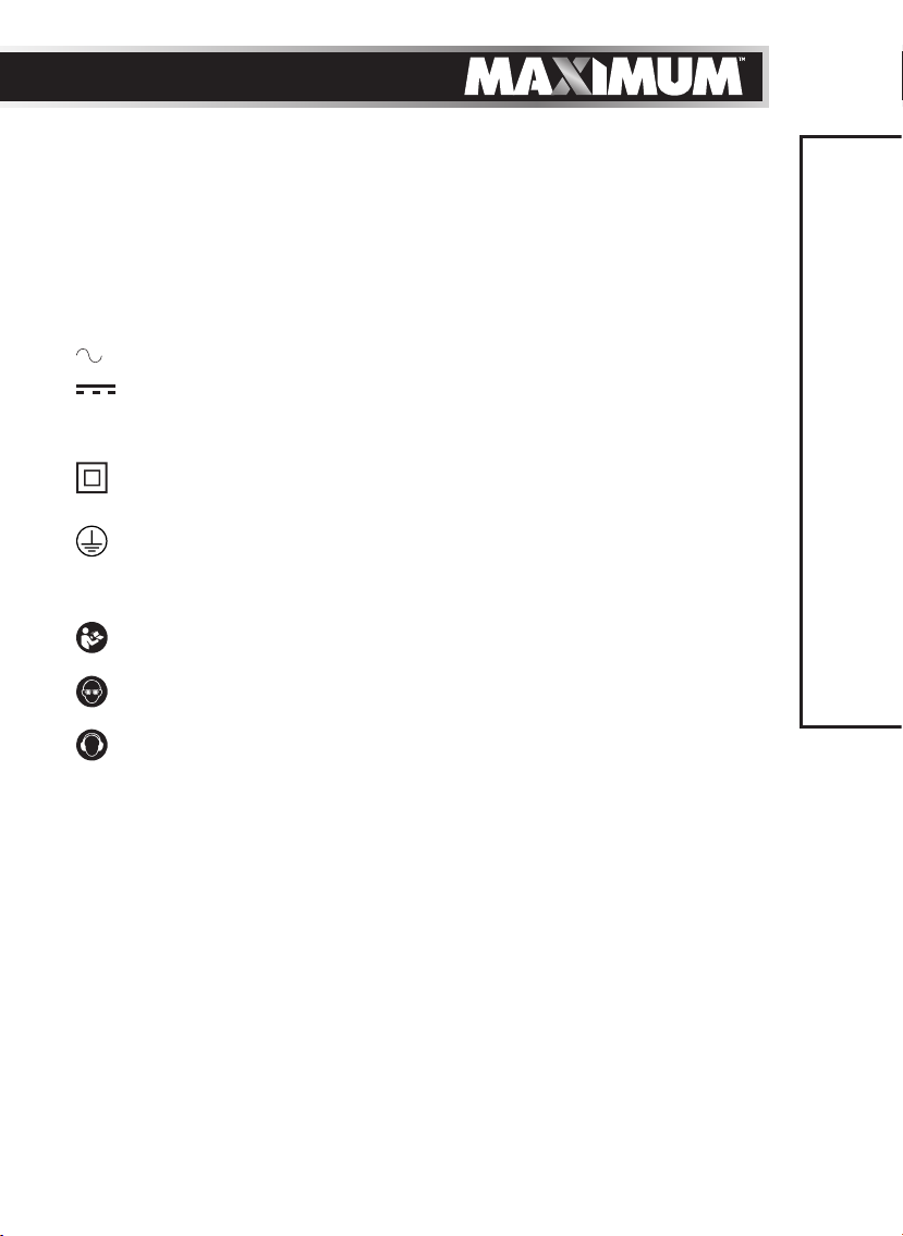
• The label on your tool may include the following symbols. The symbols and
their definitions are as follows:
V ..................... Volts
A ..................... Amperes
Hz ................... Hertz
W .................... Watts
min ................. Minutes
............... Alternating current
............. Direct current
n
................... Rated speed
n
................... No-load speed
0
............... Class II Construction
…/min ........... Revolutions or reciprocations per minute
............... Grounding terminal
BPM ............... Beats per minute
RPM ............... Revolutions per minute
.............. WARNING – To reduce the risk of injury, user must read
instruction manual.
.............. WARNING – To reduce the risk of injury always wear eye
protection.
.............. WARNING – To reduce the risk of injury always wear ear
protection.
9
SAFETY GUIDELINES
ADDITIONAL SAFETY INSTRUCTIONS FOR GRINDING OPERATIONS
• Use only wheel types that are recommended for your power tool and use
only the specific guard designed for the selected wheel. Wheels for which the
power tool was not designed cannot be adequately guarded and are unsafe.
• The grinding surface of centre-depressed wheels must be mounted below the
plane of the guard lip. An improperly mounted wheel that projects through the
plane of the guard lip cannot be adequately protected.
• The guard must be securely attached to the power tool and positioned
for maximum safety, so the least amount of wheel is exposed towards
the operator. The guard helps to protect the operator from broken wheel
fragments, accidental contact with wheel and sparks that could ignite clothing.
• Wheels must be used only for recommended applications. For example:
do not grind with the side of a cut-off wheel. Abrasive cut-off wheels are
intended for peripheral grinding; side forces applied to these wheels may
cause them to shatter.
Page 10

10
SAFETY GUIDELINES
model no. 054-4297-2 | contact us 1-888-670-6682
• Always use undamaged wheel flanges that are of correct size and shape for
your selected wheel. Proper wheel flanges support the wheel, thus reducing
the possibility of wheel breakage. Flanges for cut-off wheels may be different
from grinding wheel flanges.
• Do not use worn down wheels from larger power tools. Wheels intended for
larger power tools are not suitable for the higher speed of a smaller tool and
may burst.
KICKBACK AND RELATED WARNINGS
Kickback is the result of power tool misuse and/or incorrect operating
procedures or conditions and can be avoided by taking proper precautions, as
given below.
• Maintain a firm grip on the power tool and position your body and arms
to allow you to resist kickback forces. Always use the auxiliary handle, if
provided, for maximum control over kickback or torque reaction during startup. The operator can control torque reactions or kickback forces if proper
precautions are taken.
• Never place your hand near the rotating accessory. The accessory may
kickback over your hand.
• Do not position your body in the area where the power tool will move if
kickback occurs. Kickback will propel the tool in the direction opposite to the
wheel’s movement at the point of snagging.
• Use special care when working corners, sharp edges, etc. Avoid bouncing and
snagging the accessory. Corners, sharp edges or bouncing have a tendency to
snag the rotating accessory and cause loss of control or kickback.
• Do not attach a saw chain, wood carving blade or toothed saw blade. Such
blades create frequent kickback and loss of control.
Page 11
PACKAGE CONTENTS
High-performance angle grinder, 5" (125 mm) grinding wheel, 5" (125 mm) & 4
1/2" (115 mm) wheel guards, anti-vibration auxiliary handle, wrench, 2 extra carbon
brushes, tote, and instruction manual.
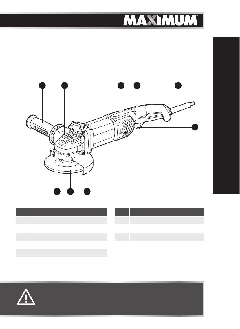
KEY PARTS DIAGRAM
1 2 543
789
11
6
KEY PARTS DIAGRAM
NO. PART NO. PART
1 Side handle 6 Trigger switch
2 Spindle-lock button 7 Wheel guard
3 Carbon brush cover 8 Grinding wheel
4 Lock-on button 9 Guard latch
5 Cord guard
WARNING!
• Remove the grinder from the carton and examine it carefully. Do
not discard the carton or any packaging material until all parts are
examined.
Page 12

12
model no. 054-4297-2 | contact us 1-888-670-6682
IMPORTANT INFORMATION
Before attempting to use this tool, become familiar with all of its operating
features and safety requirements. For optimum performance and safety, read the
following operating instructions carefully before using.
IMPORTANT INFORMATION
WARNING!
• Do not allow familiarity with the angle grinder to make you careless. A
fraction of a second of carelessness is enough to cause severe injury.
• To avoid injury, always turn the tool off and disconnect the angle grinder
from the power outlet before installing or changing the grinding wheel.
Page 13
ASSEMBLY INSTRUCTIONS
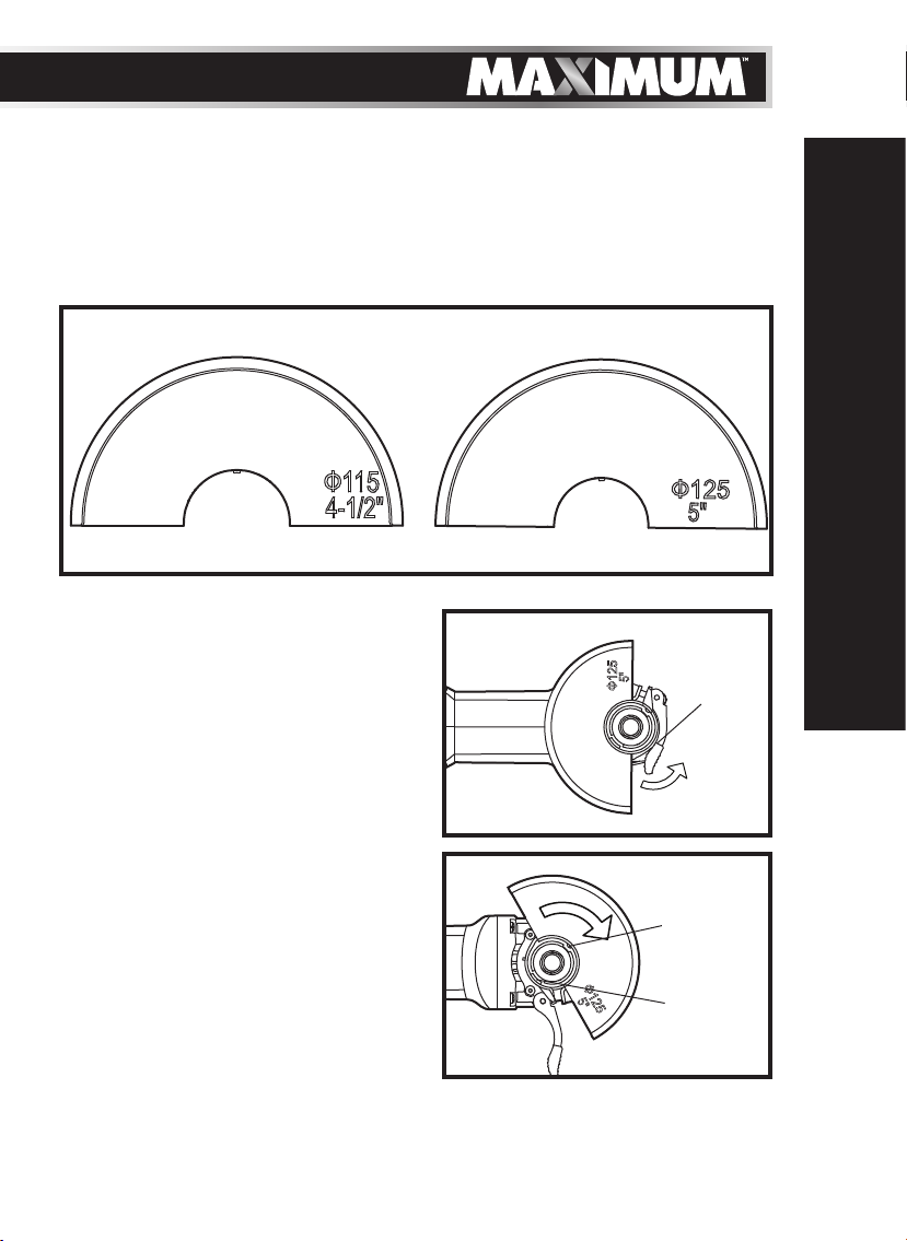
REPLACING THE WHEEL GUARD [4 1/2" (115 MM) AND 5" (125 MM)]
This grinder is supplied with 5" (125 mm) and 4 1/2" (115 mm) TYPE27 grinding
wheel guards. The size has been stamped on each guard (fig 1). Always make
sure that a wheel guard of the proper size is used when grinding with different
wheels.
g 1
13
TO REMOVE THE WHEEL
GUARD (g 2a and 2b)
1. Disconnect the plug from electrical
outlet.
2. Remove wheel and flanges from the
tool; refer to the section “INSTALLING
AND REMOVING THE GRINDING
WHEEL”.
3. Open the guard latch; refer to fig 2a.
4. Rotate wheel guard clockwise until the
lugs on the guard match the notches
on the gear box cover; refer to fig 2b.
5. Lift wheel guard off the tool.
g 2a
ASSEMBLY INSTRUCTIONS
Guard
latch
g 2b
Notches
Lugs
Page 14
14
model no. 054-4297-2 | contact us 1-888-670-6682
TO INSTALL THE WHEEL GUARD
1. Open the guard latch.
2. Align the lugs on the guard with the notches on the gear box cover.
3. Rotate wheel guard into desired working position.
4. Close the guard latch to secure the guard.
INSTALLING AND REMOVING THE GRINDING WHEEL
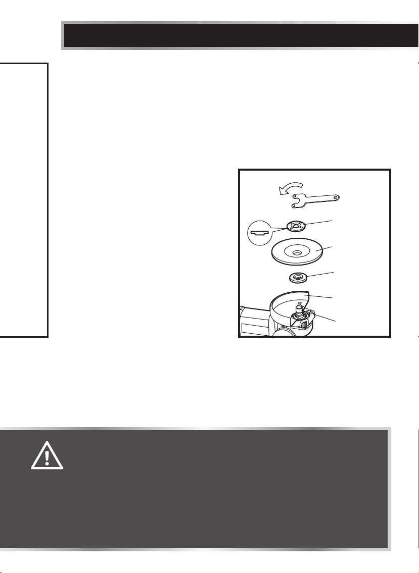
TO INSTALL A WHEEL (g 3 and 4)
1. Disconnect the plug from the electrical
outlet. Make sure the proper guard is
securely in place.
2. While pressing the spindle-lock
button, loosen the lock nut by turning
it counter-clockwise with the wrench
supplied.
3. Check to ensure that the backing flange
is properly seated on the spindle. It will
click into place on the spindle and will
ASSEMBLY INSTRUCTIONS
cause the spindle to rotate when the
backing flange is rotated.
4. Place the wheel on the spindle. Check
the rated speed on the grinding wheel.
Do not use a wheel with a rated speed lower than the speed shown on the
grinder’s nameplate.
WARNING!
• A wheel guard must be attached when using a grinding wheel. Always
keep the wheel guard between you and your work while grinding.
• You should not be able to rotate the wheel guard by hand when the guard
latch is closed. Do not operate the grinder with a loose guard or the guard
latch in the open position.
• Use only Type 27 wheels with the thickness of 1/4" (6 mm), such as the
one provided with this product. Never attach a Type 1 straight or cut-off
wheel to this angle grinder. This product is only designed for grinding.
Use for any other purpose is not recommended and creates a hazard,
which will result in serious injury.
g 3
Lock nut
Grinding
Wheel
Backing
flange
Wheel
Guard
Spindle
Page 15
15
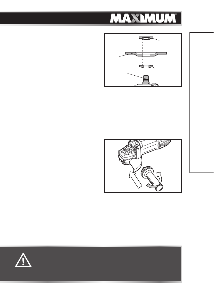
5. Thread the lock nut on the spindle with
the flat side of the flange facing up,
making sure the opening in the wheel
is positioned around the raised portion
of the lock nut (fig 4).
6. Press the spindle-lock button to keep
the spindle from moving.
7. While pressing the spindle-lock button,
tighten the lock nut by turning it
clockwise with the wrench supplied.
TO REMOVE A WHEEL
1. Disconnect the plug from the electrical outlet.
2. While pressing the spindle-lock button, loosen the lock nut by turning it
counter-clockwise with the wrench supplied.
3. Remove the wheel from the spindle.
INSTALLING THE SIDE
HANDLE (g 5)
1. Disconnect the plug from the electrical
outlet.
2. The side handle may be installed on
the right side or the left side of the
tool. Thread the side handle into the
desired operating position.
3. Securely tighten the side handle by
turning it clockwise.
g 4
Grinding
wheel
Spindle
g 5
Lock nut
Backing
flange
ASSEMBLY INSTRUCTIONS
WARNING!
• When you are trying to remove a wheel, the tool must be
completely stopped. Do not depress the spindle-lock button
until the spindle has completely stopped moving.
• The side handle should always be used during operation.
Page 16
16
model no. 054-4297-2 | contact us 1-888-670-6682
OPERATING INSTRUCTIONS
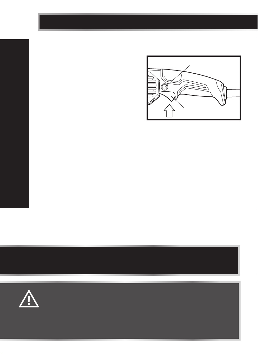
TRIGGER SWITCH (g 6)
1. To turn the angle grinder on, depress
the trigger switch.
2. To turn it off, release the trigger switch.
LOCK-ON BUTTON
The angle grinder is equipped with a
lock-on feature, which is convenient for
continuous grinding for extended period
of time.
1. Depress the trigger switch.
2. Push in and hold the lock-on button, located on the side of the handle.
3. Release the trigger switch.
4. Release the lock-on button and the angle grinder will continue running.
5. To release the lock, depress and release the trigger switch.
OPERATING INSTRUCTIONS
g 6
Lock-on button
Trigger switch
NOTICE: If the lock-on feature is engaged during use and the angle grinder
becomes disconnected from the power supply, disengage the lock-on feature
immediately.
WARNING!
• Hold the tool with both hands while starting the tool; the torque from the
motor can cause the tool to twist. Start the tool before applying to work
and let the tool come to full speed before contacting the workpiece. Lift
the tool from the work before releasing the switch.
• Do not turn the angle grinder “ON” or “OFF” while the grinder is in
contact with the workpiece. It will decrease the life of the paddle switch
and could cause damage to the workpiece.
Page 17
GENERAL OPERATION
1. For best control, hold the angle grinder firmly with one hand gripping the
side handle and the other gripping the body of the angle grinder.
2. Always position the guard so that the exposed grinding wheel is pointing
away from the operator.
3. After starting the tool, apply the grinding wheel to the workpiece.
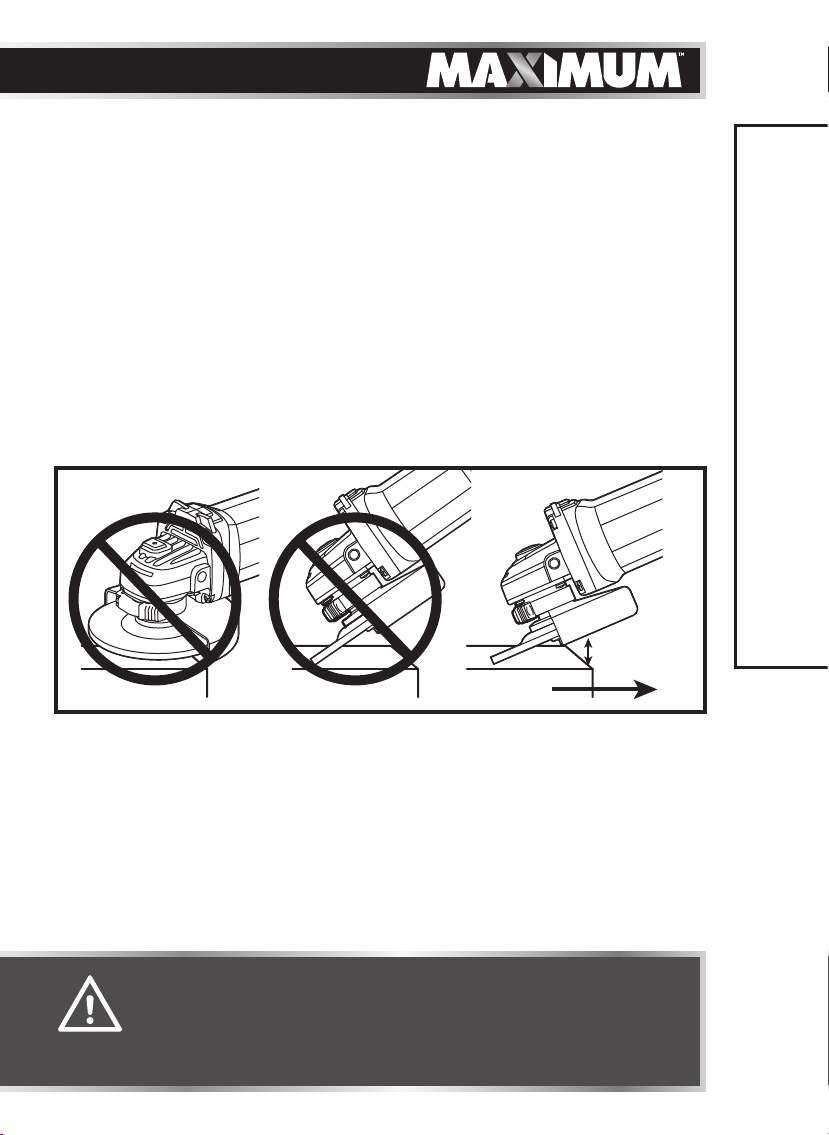
4. Tilt the angle grinder at a 10 to 15° angle for easy handling and smooth
grinding (fig 7). This will make it easier to remove the wheel from the
workpiece and will prevent overloading.
5. When using a new grinding wheel, do not move the wheel in a forward
direction (A) on the workpiece. Doing so will cause the edge of the wheel
to cut into the surface of the workpiece. While grinding, the direction of
movement should be backward, toward the operator (B in fig 7).
g 7
10°-15°
17
OPERATING INSTRUCTIONS
A B
•
WARNING!
• Do not apply unnecessary pressure. The weight of the tool applies
adequate pressure. Excessive or sudden pressure will overload the
motor, cause a drop in the speed and put dangerous stress on the
grinding wheel, possibly causing breakage and injury.
Page 18
18
model no. 054-4297-2 | contact us 1-888-670-6682
MAINTENANCE
Before cleaning or performing any maintenance, the tool should be unplugged
from the power supply. Using compressed air may be the most effective cleaning
method. Always wear safety goggles when cleaning tools with compressed air.
Do not let brake fluid, gasoline, petroleum-based products, penetrating oil, etc.,
come into contact with plastic parts. These substances contain chemicals that
can damage, weaken or destroy plastic.
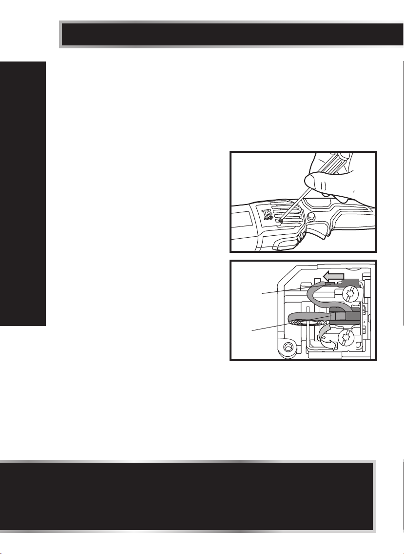
REPLACING THE CARBON BRUSHES
(g 8a and 8b)
1. Disconnect the plug from the electrical
outlet.
2. Loosen and remove the screw on the
brush cover with a screwdriver (not
included), and then lift the brush cover.
3. Push the terminal out with a straight
screwdriver; pry the spiral spring out
with a straight screwdriver.
4. Remove the older brushes and insert
the new brushes into the brush holders;
both carbon brushes should be
MAINTENANCE
replaced at the same time. Keep the
carbon brush clean and free to slip in
the holder.
5. Place the terminal inside; pry the spiral
spring back to the carbon brush.
6. Tighten the brush cover with a
screwdriver.
g 8a
g 8b
Terminal
Spiral
spring
NOTICE:
• If the tool stops working after long term use, the brushes might have
become worn. Replace them with identical carbon brushes. If you need new
brushes, please call our toll-free helpline at 1-888-670-6682.
• Make sure that the carbon brush is assembled in the right direction: the
terminal is on the top of the spiral spring.
Page 19
19
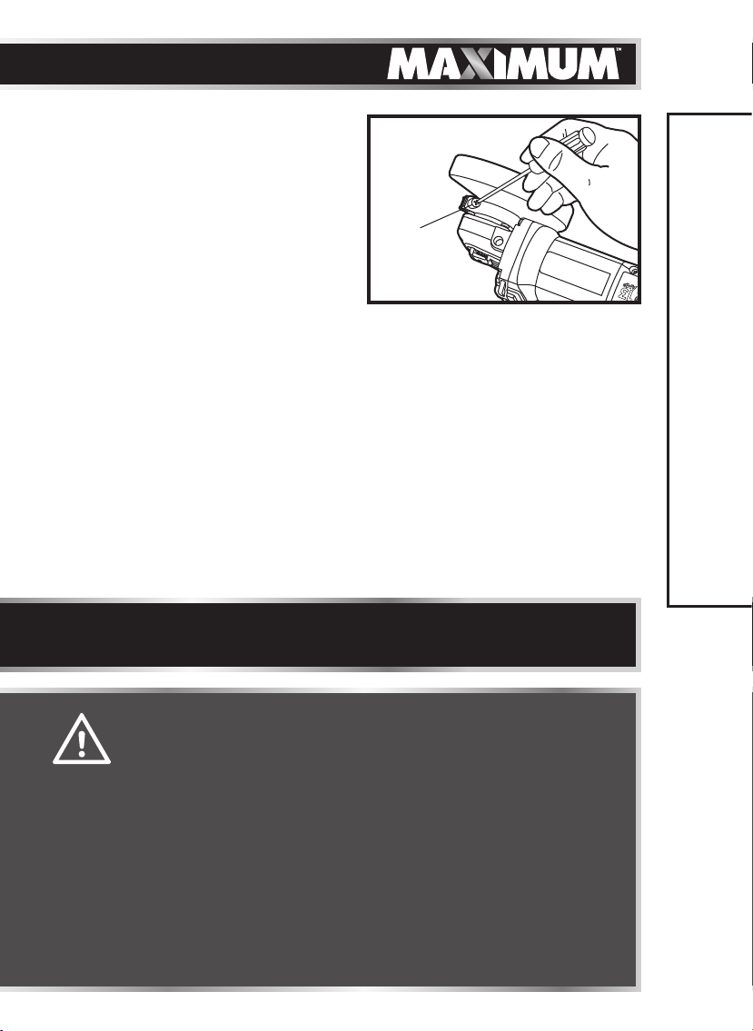
TIGHTENING THE WHEEL
GUARD (g 9)
1. Disconnect the plug from the electrical
outlet.
2. Remove the flanges and the wheel;
refer to the section “INSTALLING AND
REMOVING THE GRINDING WHEEL”.
3. Open the guard latch and rotate the
guard to a proper position.
4. Close the guard latch and tighten the screw on the guard with a screw driver
(not supplied).
g 9
Screw
NOTICE: After the wheel guard tightened, the guard should be fixed firmly
when the latch is closed and rotated normally when the latch is opened.
MAINTENANCE
WARNING!
• You should not be able to rotate the wheel guard by hand when
the guard latch is closed. Do not operate the grinder with a loose
guard or the guard latch in the open position.
• When servicing, use only identical replacement parts. The use
of any other parts may create a hazard or cause damage to
the product. For more information, call the toll-free helpline, at
1-888-670-6682.
• Use only accessories that are recommended by the manufacturer
for your model. Accessories that may be suitable for one tool
may become hazardous when used with another tool.
• Maintain tools with care. Keep cutting tools sharp and clean.
Properly maintained tools, with sharp cutting edges, are less
likely to bind and are easier to control.
• If the supply cord is damaged, it must be replaced by a specially
prepared cord available through the service organization.
Page 20

20
model no. 054-4297-2 | contact us 1-888-670-6682
TROUBLESHOOTING
PROBLEM CAUSE OF THE PROBLEM
Tool was not plugged in.
Motor does not start.
Tool is still locked on
when the plug was pulled
out.
Tool is over heated. Cool the tool.
Tool stops working.
Tool vibrates or
shakes.
Spindle lock button
cannot be used.
TROUBLESHOOTING
If the problem remains unsolved after performing the checks described above,
call the toll-free helpline at 1-888-670-6682.
Tool is forced. Do not force the tool.
Carbon brushes have
worn out.
Damaged wheel. Replace the wheel.
Loose wheel. Tighten the lock nut.
Spindle lock button is
blocked by debris.
SUGGESTED CORRECTIVE
ACTION
Check to see that the
supply cord is properly
connected to an electrical
supply.
Depress and release the
trigger switch.
Replace carbon brushes.
Clean the debris from
inside the spindle lock
button.
Page 21
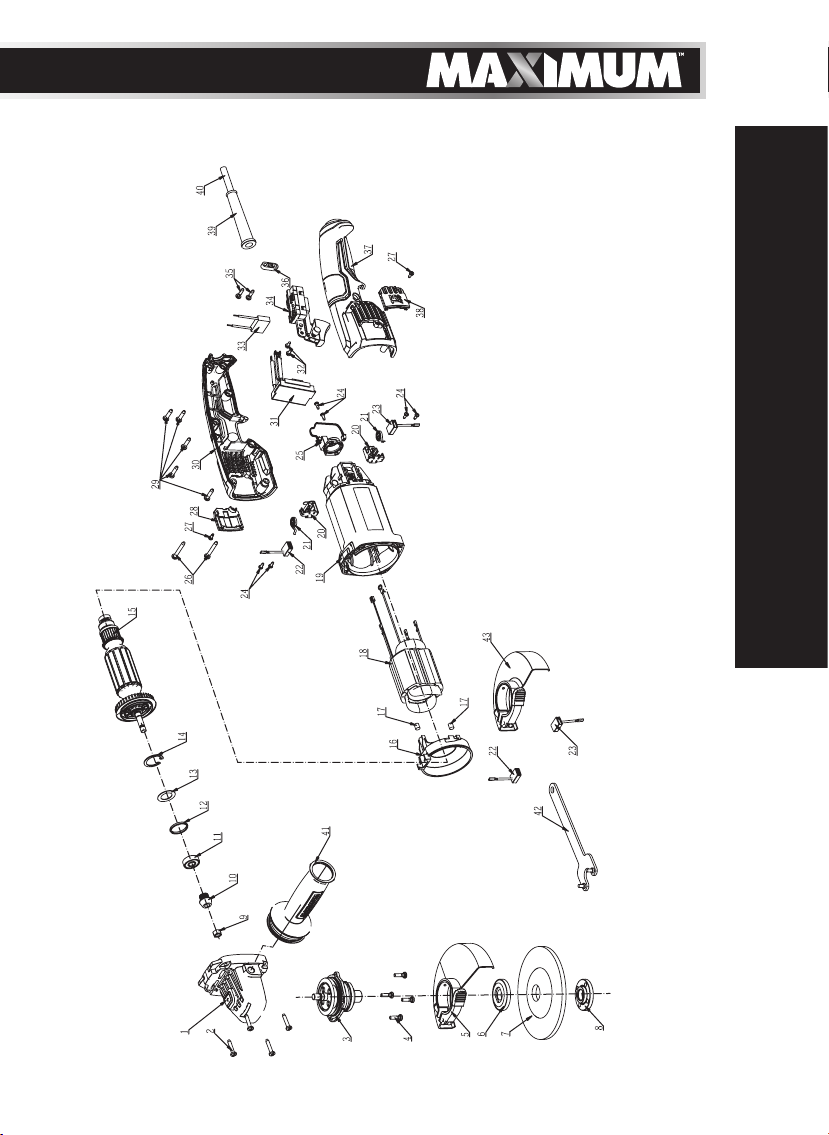
EXPLODED VIEW
21
PARTS LIST
Page 22

22
PARTS LIST
model no. 054-4297-2 | contact us 1-888-670-6682
No. Part No. Description No. Part No. Description
1 2823582000
2 5610284000 Tapping Screw 24 5610010000 Tapping Screw
3 2824769000
4 5620360000
5 2824705000
6 2820067000 Inner Flange 28 3128536000
7 3810003000
8 3550130000 Outer Flange 30 3322114000 Right Handle
9 5630224000 Nut 31 2830161000
10 3551562000 Pinion 32 3700137000 Flange Screw
11 5700008000 Ball Bearing 33 4970040000 Capacitor
12 3121029000 Rubber Ring 34 4870592000 Switch
13 5650368000
14 5660174000
15 2824768000 Rotor Set 37 3322113000 Left Handle
16 3128494000 Fan Baffle 38 3128538000
17 3121006000 Rubber Insert 39 3121050000 Cord Guard
18 2740409000 Stator 40 4810002000
19 3128495000 Motor Housing 41 3322123000 Side Handle
20 2800259000
21 3660268000 Spiral Spring 43 2824704000 Guard Assembly
22 4960331000 Carbon Brush
Gear Case
Assembly
Spindle
Assembly
Hexagon
Lobuar Screw
Guard
Assembly
Grinding
Wheel Slice
Adjusting
Washer
Circlips For
Hole
Brush Support
Assembly
23 4960330000 Carbon Brush
25 2830159000
26 5620169000 Tapping Screw
27 5610283000 Tapping Screw
29 5620157000
35 5610264000
36 3120234000 Cord Anchorage
42 3704780000 Wrench
Electric
Assembly
Right Brush
Cover
Hexagon Socket
Screw
Electric
Assembly
Hexagon
Lobular Screw
Left Brush
Cover
Power Cord and
Plug
If any parts are missing or damaged, or if you have any questions, please call the
toll-free helpline at 1-888-670-6682.
Page 23
5-YEAR LIMITED WARRANTY
This MAXIMUM product is guaranteed for a period of 5
years from the date of original retail purchase against
defects in workmanship and materials only and is
subject to the following components:
a) Component A: The carrying case is guaranteed for
a period of 1-year from the date of original retail
purchase against defects in workmanship and
materials.
b) Component B: Accessories, including drill bits and
saw blades, do not carry a warranty.
Subject to the conditions and limitations described
below, this product, if returned to us with proof of purchase within the stated
warranty period and if covered under this warranty, will be repaired or replaced
(with the same model, or one of equal value or specification), at the sole discretion
of the Maximum Canada authorised repair centre (“Service Provider”). We will bear
the cost of any repair or replacement and any costs of labour relating thereto.
These warranties are subject to the following conditions and limitations:*
a) a bill of sale verifying the purchase and purchase date must be provided;
b) defects in workmanship and material to be assessed and determined by the
Service Provider;
c) this warranty will not apply to any product or part thereof which is worn or
broken or which has become inoperative due to abuse, misuse, accidental
damage, neglect or lack of proper installation, operation or maintenance
(as outlined in the applicable owner’s manual or operating instructions);
d) this warranty does not apply to normal wear and tear or to expendable parts
or accessories (including drill bits and saw blades) that may be supplied with
the product that by their nature have a limited life span and are expected to
become inoperative or unusable after a reasonable period of use;
e) this warranty will not apply to routine maintenance and consumable items
such as, but not limited to, fuel, lubricants, vacuum bags, blades, belts,
sandpaper, bits, fluids, rubber o-rings, tune-ups or adjustments;
f) this warranty excludes the following components that may accompany your
product:
(1) the carrying case, which is only for a period of 1-year from the date of
original retail purchase against defects in workmanship and materials.
(2) accessories, including drill bits and saw blades, which do not carry a
warranty of any kind.
g) this warranty will not apply where damage is caused by repairs made or
attempted by others (i.e. persons not authorized by the manufacturer), and
any such unauthorized repairs or attempted repairs shall void this warranty
in its entirety;
23
WARRANTY
Page 24

24
h) this warranty will not apply to any parts other than original parts, except to
i) this warranty will not apply to any product that was sold to the original
j) this warranty will not apply to any product or part thereof if any part from
k) this warranty will not apply to normal deterioration of the exterior finish,
l) this warranty will not apply to component parts sold by and identified as
m) any products replaced by the retailer in attempt to fulfill warranty
WARRANTY
n) the retailer and manufacturer’s sole obligation and the purchaser’s sole
model no. 054-4297-2 | contact us 1-888-670-6682
the extent that the retailer or manufacturer or persons authorized by either
of them have repaired or replaced them;
purchaser as a reconditioned or refurbished product (unless otherwise
specified in writing);
another manufacturer is installed therein or any repairs or alterations have
been made or attempted by unauthorized persons;
such as, but not limited to, scratches, dents, paint chips, or to any corrosion
or discolouring by heat, abrasive and chemical cleaners;
the product of another company, which shall be covered under that product
manufacturer’s warranty, if any;
obligations is subject to the original product warranty conditions and
related time period as initiated by the original date of purchase; if product
is purchased in Quebec, the warranty term will be extended for a period
equal to the time during which the Quebec retailer possesses the product in
attempt to fulfill warranty obligations; replaced product will not default to
new product warranty conditions; and
remedy under this warranty shall be as set out herein. The warranties
contained herein are not transferable and are given only to the purchaser.
FURTHER, THE WARRANTIES SET OUT HEREIN ARE IN LIEU OF ALL
OTHER WARRANTIES OR CONDITIONS, WHETHER EXPRESS, IMPLIED OR
STATUTORY (INCLUDING SUCH AS ARISE UNDER THE SALE OF GOODS
ACT OR THE INTERNATIONAL SALE OF GOODS ACT), ARISING OUT OF A
COURSE OF DEALING OR USAGE OF TRADE OR OTHERWISE, INCLUDING,
SUBJECT TO APPLICABLE LAW, ANY IMPLIED WARRANTIES OR
CONDITIONS OF MERCHANTABILITY, MERCHANTABLE QUALITY, FITNESS
OR ADEQUACY FOR A PARTICULAR PURPOSE OR USE, AND ALL OTHER
SUCH WARRANTIES ARE EXPRESSLY DISCLAIMED BY THE RETAILER AND
MANUFACTURER.
Additional Limitations
This warranty applies only to the original purchaser and may not be transferred.
This warranty applies for a period of 5 years from the date of original retail
purchase, as indicated on the bill of sale.
Neither the retailer, Maximum Canada, nor the manufacturer shall be liable for
any other expense, loss or damage, including, without limitation, any indirect,
incidental, consequential or exemplary damages arising in connection with the
sale, use or inability to use this product.
Page 25

Under no circumstances shall the retailer, Maximum Canada, or manufacturer
be liable to the purchaser for any claim for (a) indirect, special, punitive,
incidental, exemplary, or consequential damages, (b) compensation for loss of
profits, anticipated revenue, savings or goodwill, or other economic loss of the
purchaser, (c) exemplary, aggravated or punitive damages howsoever incurred,
(d) contribution or set-off in respect of any claims against the purchaser, (e)
any damages whatsoever relating to third party products or services or the
purchaser’s materials, or (f) any damages whatsoever relating to interruption,
delays, errors or omissions; in each case under any theory of law or equity,
arising out of or in any way related to this warranty, even if advised of the
possibility thereof. Notwithstanding any provision herein or entitlement of
the purchaser at law, in equity or otherwise, in no event shall the liability of
the retailer or manufacturer under this warranty, whether in contract, tort,
product liability or otherwise, exceed, in the aggregate, the amount paid by the
purchaser to the retailer for the product to which this warranty applies.
*Notice to Consumer
This warranty gives you specific legal rights, and you may have other rights, which
may vary from province to province. The provisions contained in this warranty are
not intended to limit, modify, take away from, disclaim or exclude any statutory
warranties set forth in any applicable provincial or federal legislation.
In addition to the 5-Year Limited Warranty, this MAXIMUM product is covered by our:
1-Year Repair Warranty
Maximum Canada will maintain this product and replace critical parts which
have worn beyond reasonable use through normal use of such product, any time
during the first year after purchase.
The following are excluded from this 1-Year Repair Warranty:
a) missing or damaged parts or components that are a result of abuse or
misuse;
b) any wear and tear to non-critical parts or accessories that do not affect the
core function of the product.
25
WARRANTY
90-Day Satisfaction Guarantee
If you are not completely satisfied with the performance of your MAXIMUM
product for any reason, you can return it within 90 days from the date of
purchase with proof of purchase for exchange or a full refund.
Made in China
Imported by
MAXIMUM Canada Toronto, Canada M4S 2B8
Page 26

 Loading...