

Page 1
Maxim > Design Support > Technical Documents > User Guides > APP 3358
Page 1 of 21
Keywords: onewireviewer, 1-wire,ibutton, onewire, viewer, software, evaluation, eval kit, java, web start, webstart, user's guide, manual, howto, debugging
USER GUIDE 3358
OneWireViewer User's Guide, Version 1.5
By: Bernhard Linke, Principal Member Technical Staff
Sep 25, 2009
This User's
Abstract:
devices.
Introduction
The OneWireViewer is a Java™ -based software package to explore Maxim's 1- Wire and iButton devices with a personal computer. The 1-Wire and iButton devices
communicate over a single data line plus ground reference, using the 1-Wire protocol. Several 1-Wire adapters are available for USB and serial ports. The
OneWireViewer provides a user interface to evaluate the unique features of 1 - Wire and i
Hygrochron™ (real-time temperature and humidity), A to D (analog to digital), clock, memory, and file operations.
Installation
Refer to application note 4373, "OneWireViewer and iButton® Quick Start Guide " for the installation instructions for the 1 - Wire Drivers, which also install the
OneWireViewer. For additional/expanded help, see application note 5057, "OneWireViewer Tips and Tricks ," starting with the section Identifying the System.
Uninstalling
Refer to the application note 5057, " OneWireViewer Tips and Tricks ," section How to Install a Newer OneWireViewer Version.
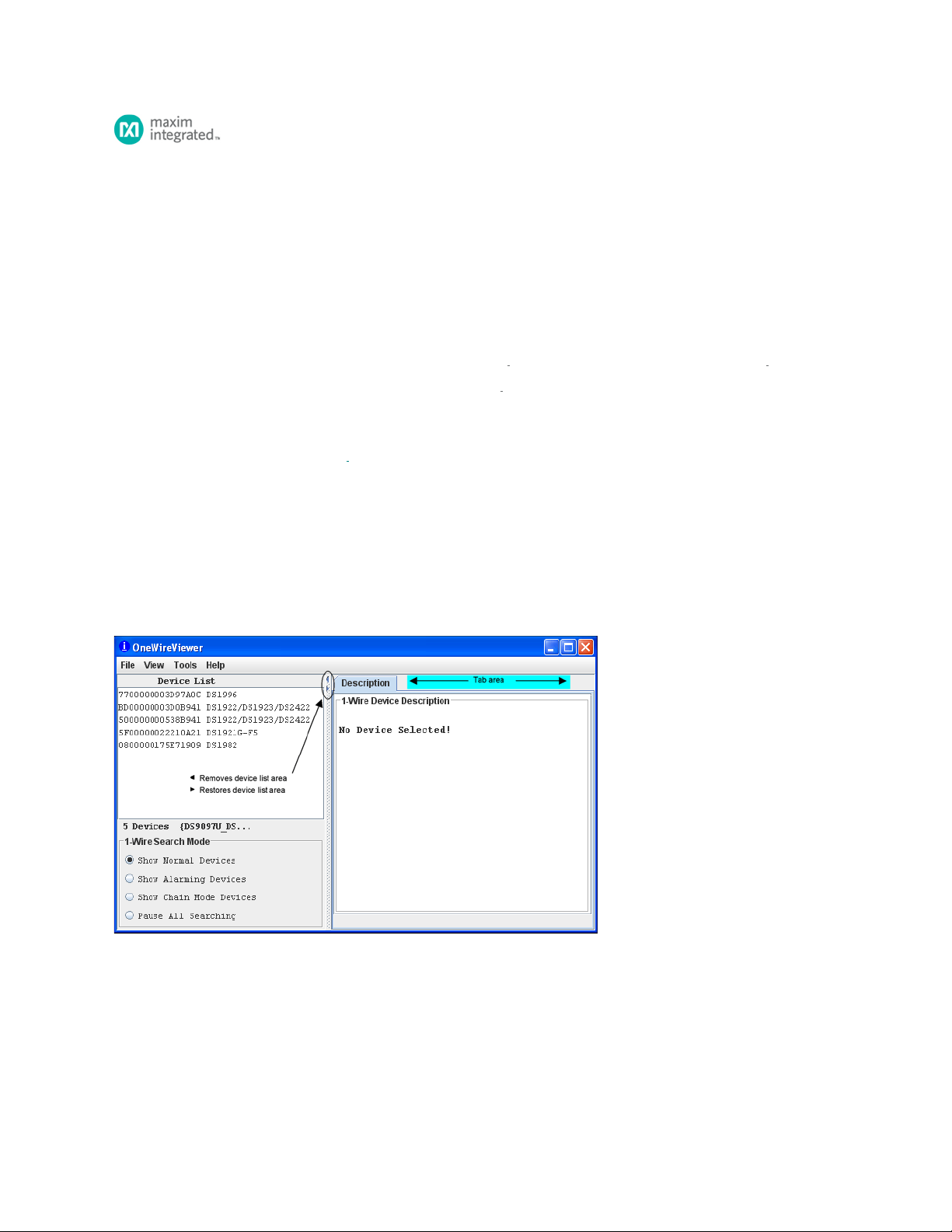
Program Main Window
The main window of the OneWireViewer consists of four areas: Device List (top left), 1-Wire Search Mode (bottom left), Tab area (to the right) and menus (top
row). The width of the device list/search mode area can be adjusted by horizontally moving the vertical scroll bar that separates these areas from the tab area. The
Device List/1-Wire Search Mode areas can be removed/restored by clicking on one of the tiny triangles to the right of the device list.
Guide explains the OneWireViewer software program and how it can be used to evaluate the unique features of 1 -Wire® and iButton®
Button products, including Thermochron® (temperature logging),
Viewer Menus
File
Close (to exit program)
Has a subtitle Alt-1 (instead of Alt+F4). The Program will end with Alt+F4 as well as Alt+1. The '1' must be pressed on the normal keypad, not the numeric keypad,
to be accepted.
View
Show Message Log (to read error messages)
Opens a new window that displays a device access log and error messages.
Page 2

Show Tab in New Window (to view multiple functions or devices simultaneously)
Page 2 of 21
To use this function, first select a device, then select one of the available tabs. Then use Show Tab in New Window, which moves the selected tab into a window of
its own. The main window will then revert back to the Description tab.
Show Device Alternate Names (to see alternate names in the device list)
Example: Thermochron instead of DS1921G-F5 to the right of the ROM ID
Tools
Pick Adapter (to change the communication port and 1-Wire port adapter)
Opens a new window for selecting one of several 1 -Wire port adapters, port type, and port number. For more information see application note 5057,
"OneWireViewer Tips and Tricks," section How to Change 1-Wire Adapters and Ports .
XML Tagging (to load device tags that can be displayed in the device list)
Opens a new window to select the file that holds the XML tags of the devices in use. See application note 158, "1 -Wire® Tagging with XML," for tag specification
and how to create tag files that are compatible with the OneWireViewer.
1- Wire Speed (to select the preferred 1-Wire speed)
Allows selection of standard speed or overdrive speed. Most 1-Wire devices support both speed modes. To use overdrive speed, the port adapter must also support
overdrive. If overdrive is selected and the port adapter does not support overdrive, an error message will appear when trying to access an overdrive-supporting 1Wire device.
Device Poll Rate (to set the frequency at which the 1-Wire net is searched for devices)
The rates are 1s, 5s, 10s, 30s, 1min, 5min, and immediate poll. The typical value is 1s, which yields the fastest response.
Help
About (displays the version numbers of the software components that comprise the OneWireViewer)
Opens a window that displays: the site from which the source code of the 1-Wire API and OneWireViewer can be downloaded; the API version; the version numbers
of the various viewers; and the location of the onewireviewer.properties file on the local hard drive. The OneWireViewer is provided as a source code example in the
1- Wire API for Java Kit.
Viewer Window Areas
Device List
This is the area that displays the ROM IDs of devices on the network and the device part numbers/names. The 1-Wire Search Mode controls whether a device is
included in the list. Devices that arrive on the network are appended at the bottom of the list. If XML tags have been defined (see the section Viewer Menus, Tools,
XML Tagging above), the device list shows the tags instead of the part numbers/names. In addition, only the functionality associated with their tags is exercisable.
Below the device list, the total number of devices on the network and the type of port adapter are displayed. In this example, the adapter is a DS9097U. The { }
brackets around the adapter name indicate that it uses a native TMEX driver.
1- Wire Search Mode (affects the contents of the device list)
Show Normal Devices
When checked, the list shows all devices on the network.
Show Alarming Devices
When checked, the list shows only devices that respond to the Conditional Search ROM command, e.g., because of an alarming condition.
Show Chain Mode Devices
When checked, the list shows only devices that support the Chain Mode. This feature allows detecting the physical sequence of all the devices in a linear network
that are wired for Chain Mode. An example device is the DS28EA00 1-Wire digital thermometer.
Pause All Searching (to stop/restart searching the network for arriving/departing devices)
When checked, the 1-Wire network is no longer searched. This minimizes the communication traffic on the network (e.g., to facilitate catching events with an
oscilloscope), and freezes the content of the device list. An error message will be generated if one selects a device that has departed from the network. With the
searching paused, one cannot access devices that have arrived because they are not included in the device list. To end the pause, check Show Normal Devices.
Tab Area
Once a device is selected, the Description tab appears with a short description of the device. Depending on the device, additional tabs may appear that provide
access to the applicable device function viewers. See the Supported Devices table below for a list of devices and applicable device viewers.
Page 3
The 1-Wire and iButton products support a broad set of features. The following table, sorted by family code, shows the applicable device function viewers.
Page 3 of 21
Page 4
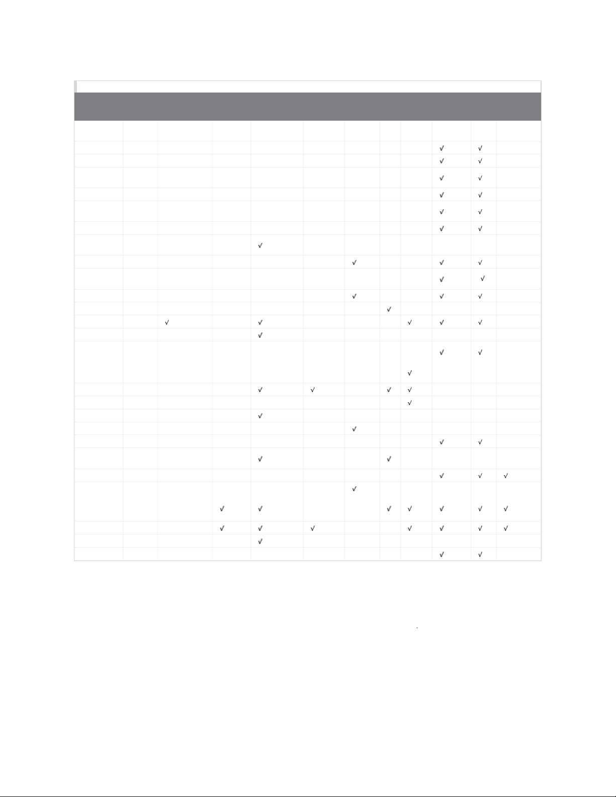
Supported Devices
Page 4 of 21
Supported
Devices
DS1990A,
DS1990R
DS1993L 06
DS1992L 08
DS1982,
DS2502
DS1995L 0A
DS1985,
DS2505
DS1996L 0C
DS1920,
DS1820
DS2406 12
DS1971,¹
DS2430A¹
DS28E04 1C
DS2450 20
DS1921 21
DS1822 22
DS1973,
DS2433
DS1904,
DS2415
DS2438 26
DS2417 27
DS18B20 28
DS2408 29
DS2431 2D
DS2760,
DS2762
DS1977 37
DS2413 3A
DS1922,²
DS2422²
DS1923 41
DS28EA00³ 42
DS28EC20 43
¹It is possible
²A-to- D support applies to the DS2422 only.
³This device supports Chain Mode; see data sheet for more information.
Family
Code
01
09
0B
10
14
23
24
30
41
to format this device; however, there is no memory left to store a file.
Thermochron Mission Temperature Humidity SwitchAtoDClock Memory File Password
( )
(
)
Device Function Viewers
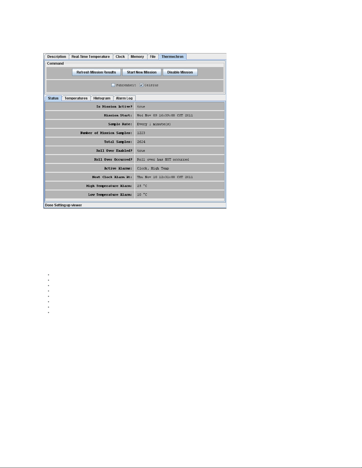
Thermochron (Temperature Logging)
The Thermochron viewer gives real- time information on the mission parameters and status of the selected Thermochron iButton connected to the OneWireViewer.
The user can start a new mission, end (disable) a running mission, view and download the mission's temperature log, and see (but not download) the mission's
temperature histogram and alarm log. Similar to the Mission viewer, the Thermochron viewer is used only for the DS1921 series of temperature loggers and their
features. See also the Supported Devices table above.
The tab structure of the Thermochron viewer consists of two areas: Command (top), and device data tabs (bottom). The Command tab includes three buttons to
operate the device's logging function and to select the temperature scale (°C or °F). Depending on the size of the Thermochron tab, there can be scroll bars for both
areas.
Page 5
Sample Thermochron Viewer Tab
Page 5 of 21
Thermochron Viewer Commands
Refresh Mission Results (to read device status, temperature, histogram, and alarm log)
This allows a mission to be monitored in progress without changing device viewers.
Start New Mission (to allow the user to enter all data necessary to start a new mission)
This command opens a new window in which the user enters the parameters for the next mission.
Disable Mission (to stop a running mission)
This command stops a mission. The collected data remains stored in the device.
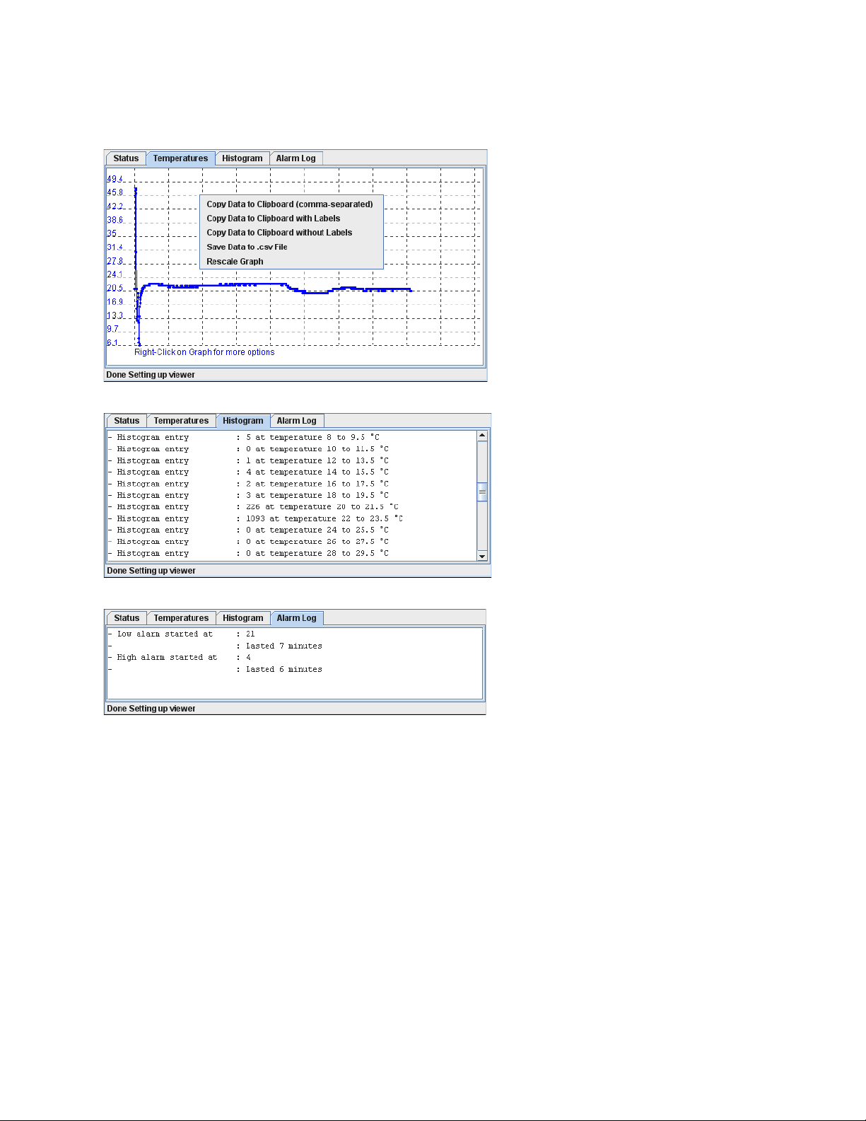
When the Thermochron Tab is active, the Thermochron viewer:
Automatically reads the device status, temperature, histogram, and alarm log.
Automatically displays the device status on the Status tab.
Displays the temperature log as a graphic (if you open the Temperatures tab).
Displays the temperature histogram in text form (if you open the Histogram tab).
Displays the alarm log in text form (if you open the Alarm Log tab).
Allows the temperature scale to be changed between °C (default) and °F; the selected scale is memorized.
Allows activation of automatic rescaling of the temperature log graph.
Allows the graph data to be exported by using the clipboard or saving as a CSV (Excel®) file.
Page 6
Sample Temperature Log Graphic
Page 6 of 21
Sample Histogram
Sample Alarm Log
Page 7
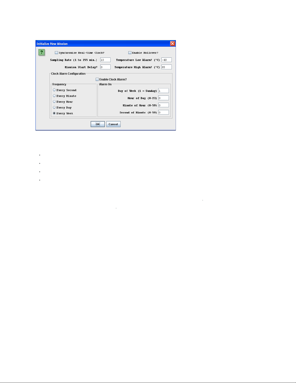
Start New Mission Window (default)
Page 7 of 21
It is recommended that you synchronize the device's real - time clock (RTC) to the PC. Enter the mission start delay in minutes. Sampling rate, mission start delay,
temperature alarms, and rollover depend on the technical requirements of the mission. See the respective DS1921-series data sheets for guidelines. The clock
alarm functions are not relevant for a device on a mission. The default settings, therefore, can be accepted.
Notes:
The time reference in the alarm log (e.g., "Low alarm started at: 21") indicates minutes after the start of the mission. To find the day and time when the alarm
occurred, manually add the indicated time to the mission start date and time.
The Thermochron viewer does not enable the temperature-high and temperature-low alarm search. As a result, if a temperature alarm occurs during the
mission, the device will not be identified as an alarming device unless there is also a timer alarm.
For the alarm -frequency and alarm -time values to be updated in the device, Enable Clock Alarm? must be checked. Otherwise, the current (i.e., previous
mission's) settings remain in effect for the new mission.
When a mission extends across time zones, the time shown in the exported data (clipboard or csv file) refers to the time at the location where the mission was
started.
Mission (Temperature and Humidity Logging)
The Mission viewer gives real-time information on the mission parameters and status of the selected Temperature Logger iButton connected to the OneWireViewer.
The user can start a new mission, end (disable) a running mission, view and download the mission's temperature and humidity. The Mission viewer is similar to the
Thermochron viewer, but is used for the DS1922 series of i
logger. See also the Supported Devices table above.
The tab structure of the Mission viewer consists of two areas: Command (top), and device data tabs (bottom). The Command tab includes three buttons to operate
the logging function of the device, and to select the temperature scale (°C or °F). Depending on the size of the Mission tab, there may be scroll bars for both areas.
Button products, the DS1923 Hygrochron and its features, and the DS2422 1-Wire temperature/data
Page 8

Sample Mission Viewer Tab
Page 8 of 21
Mission Viewer Commands
Refresh Mission Results (to read device status, temperature log, and data log)
This allows a mission in progress to be watched without changing device viewers. If passwords are enabled for the device, the user must first use the Password
viewer command Set Software Passwords before access is granted to device data.
Start New Mission (to allow the user to enter all data necessary to start a new mission)
This command opens a new window in which the user enters the parameters for the next mission. If passwords are enabled for the device, the user must first use
the Password viewer command Set Software Passwords, before access is granted to device data.
Disable Mission (to stop a running mission)
This command stops a mission. The data collected remains stored in the device. If passwords are enabled for the device, the user must first use the Password
viewer command Set Software Passwords, before access is granted to device data.
When the Mission tab is active, the Mission viewer:
Automatically reads the device status, temperature log, and data log.
Automatically displays the device status on the Status tab.
Displays the temperature log as a graphic (if you open the Temperature Data Log tab).
Displays the humidity or data log as a graphic (if you open the Humidity Data Log or Data tab).
Allows the temperature scale to be changed between °C (default) and °F; the selected scale is memorized.
Allows activation of automatic rescaling of the log graphs.
Allows log data to be exported by using the clipboard or saving as a CSV (Excel) file.
Page 9
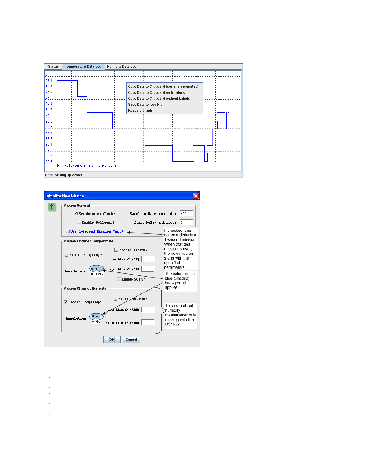
Sample Temperature Data Log Graphic (Humidity Data Log looks similar)
started.
Page 9 of 21
Start New Mission Window (default)
It is recommended that you synchronize the device's RTC to the PC. Enter the sampling rate in seconds (between samples). Enter the mission's Start Delay in
minutes. SUTA means Start mission Upon Temperature Alarm. Sampling rate, mission start delay, resolution, alarms, and rollover depend on the technical
requirements of the mission. See the respective device data sheets for details and guidelines.
Notes:
Mission Samples Count on the Status tab indicates the number of valid samples in the datalog memory. This number stops incrementing when the memory is
full.
Total Mission Samples indicates the number of samples taken during a mission. This number continues incrementing when a rollover occurs.
The Use 1-Second Mission Test ? is not needed for B1 revision parts (date code 2007 and newer; serial numbers 005A900h to 005C09Fh, 0064200h and
higher).
Although the part is found as an alarming device, a Temperature High Alarm is not flagged on the Status tab. If there is a Temperature Low Alarm, both the
high and low alarm are flagged on the Status tab.
When a mission extends across time zones, the time shown in the exported data (clipboard or csv file) refers to the time at the location where the mission was
Page 10

Password
Page 10 of 21
The Password viewer allows the user to set, enable, and disable passwords on a 1-Wire device, and to input the device -specific read and write passwords into the
viewer.
The tab structure of the Password viewer consists of two areas: Info (top) and Config (bottom). The Config tab has three buttons to set the software passwords, set
the device passwords, and to enable/disable the password protection on the 1-Wire device. Depending on the size of the Password tab, there may be scroll bars for
the Info area.
Password Viewer Tab
Password Viewer Commands
Set Software Passwords (to input the read and write password of the device into the software)
If the device has passwords enabled, the viewer needs to know the passwords to access the device. This command prompts the user to enter a read password in a
separate small window. Once the read password is entered, the user is asked to enter the full- access password. The viewer does not memorize the passwords
after the session with a particular device is closed. Passwords are 8-byte hexadecimal strings.
Set Device Passwords (to write a read password and a full-access password to the device)
If the user wants to activate passwords with the device, the passwords must first be written to the device and then enabled to take effect. This command prompts
the user to specify/enter a read password in a separate small window. Once the read password is entered, the user is asked to enter the full- access password. Next
the passwords are written to the respective device registers. The viewer does not memorize the passwords after the session with a particular device is closed.
Passwords entered with this command are automatically taken as software passwords; there is no need to reenter these passwords as software passwords.
Passwords need to be entered as 8 -byte hexadecimal strings.
Enable/Disable Passwords on Device (to enable or disable the use of passwords with the device)
This command allows the user to activate (enable) passwords that were written to the device previously. If passwords are enabled, this command allows the user to
disable them. This command does not erase passwords in the device.
Real-Time Temperature
The Real- Time Temperature viewer gives a real- time temperature reading of the selected 1-Wire temperature device connected to the OneWireViewer. The real time temperature log on the screen is created from temperature data stored in the PC's memory. This is different from Thermochron and Mission viewers, where the
temperature logging is performed inside an i
The tab structure of the Real- Time Temperature viewer consists of three areas: Info (top), Graph (bottom left), and Thermometer (bottom right). Depending on the
size of the Real-Time Temperature tab, there may be scroll bars for the Thermometer, Graph, and Info area. The Real -Time Temperature viewer applies to devices
that contain a digital thermometer. See the Supported Devices table above for the list of devices.
Button, whether or not the device is connected to the OneWireViewer.
Page 11

Sample Real-Time Temperature Tab
Page 11 of 21
When the Real -Time Temperature tab is active, the Real-Time Temperature viewer:
Continuously issues the device- specific command to perform a temperature conversion.
After each conversion reads the temperature registers of the selected device.
Converts the reading from the device- specific format into a conventional format.
Displays the result as a number, graph, and thermometer scale.
Compresses the horizontal scale of the graph, as needed, to display additional readings.
Allows the temperature scale to be changed between °C (default) and °F; the selected scale is memorized.
Allows the resolution of the temperature display (some devices only) to be changed.
Allows activation of automatic rescaling of the graph.
Allows graph data to be exported by using the clipboard or saving as a CSV (Excel) file.
Notes:
The Real- Time Temperature viewer closes whenever the selected device is found to be missing from the network or when another device is selected.
To keep the Real- Time Temperature viewer running while evaluating other devices, first activate the Real-Time Temperature viewer. Then on the View menu
(see Program Main Window), select Show Tab in New Window which will restart the Real-Time Temperature viewer in a new window. This separate window
will remain open, even if the device disappears from the network.
With the DS1922L, DS1922T, and DS1923, the temperature readings displayed are software corrected. For the DS1922E, software correction does not apply.
The Real- Time Temperature viewer cannot read the temperature of a Thermochron (DS1921, DS1922, or DS1923) that is currently running a mission.
Real-Time Humidity
The Real- Time Humidity viewer gives a real -time humidity reading of the selected 1-Wire humidity device connected to the OneWireViewer. The real -time humidity
log on the screen is created from humidity data stored in the PC's memory. This is different from Mission viewer, where the humidity logging is performed inside an
Button whether or not it is connected to the OneWireViewer.
i
The tab of the Real- Time Humidity viewer consists of three areas: Info (top), Graph (bottom left), and Humidity (bottom right). Depending on the size of the
Humidity tab, there may be scroll bars for the graph and/or humidity area. The Real-Time Humidity viewer applies primarily to the DS1923. The viewer may also
support other devices that can be set up to measure humidity. See the Supported Devices table above for the list of devices.
Page 12

Sample Real-Time Humidity Tab
Page 12 of 21
When the Real -Time Humidity tab is active, the Real-Time Humidity viewer:
Continuously issues the device- specific command to perform a humidity conversion.
After each conversion reads the humidity registers of the selected device.
Converts the reading from the device- specific format into a conventional format.
Displays the result as a number, graph, and humidity scale.
Compresses the horizontal scale of the graph, as needed, to display additional readings.
Allows activation of automatic rescaling of the graph.
Allows graph data to be exported by using the clipboard or saving as a CSV (Excel) file.
Notes:
The Real- Time Humidity viewer closes whenever the selected device is found to be missing from the network or when another device is selected.
To keep the Real- Time Humidity viewer running while evaluating other devices, first activate the Real- Time Humidity viewer. Then on the View menu (see
Program Main Window ), select Show Tab in New Window which will restart the Real -Time Humidity viewer in a new window. This separate window will remain
open, even if the device disappears from the network.
To watch humidity and temperature simultaneously, open the Real -Time Humidity and Real - Time Temperature viewers in separate windows.
With the DS1923, the humidity readings displayed are software corrected; they are not compensated for temperature or saturation drift.
The Real- Time Humidity viewer cannot read the humidity of a DS1923 that is currently running a mission.
Switch
The Switch viewer gives real- time information on the I/O channels of the selected 1-Wire addressable switch device connected to the OneWireViewer. This
information includes the channel's state, the logic level at its output, and the state of the associated activity latch. The user can change (toggle) the state of the I/O
channel and clear its activity latch. Each I/O channel of a multichannel addressable switch device can be operated individually.
The tab of the Switch viewer consists of two areas: Features (top), and Channels (bottom). The Features area lists device-specific characteristics. The number of
switches (i.e., number of channels) for the selected device is indicated by the number of channel boxes in the channels area. A digital switch can be closed ( State =
true) or open ( State = false). Level shows the logic equivalent of the voltage at the switch output. Each channel has two command buttons associated with it.
Depending on the size of the Switch tab and/or the device, there may be scroll bars for both areas. The Switch viewer applies to all devices that contain one or
more electronic switches. See the Supported Devices table above for the list of devices.
Page 13

Sample Switch Tab
Page 13 of 21
Switch Viewer Channel Commands
Toggle State (to toggle the state of the switch between on and off)
This command allows the switch's state to be changed through the 1-Wire network.
Clear Activity (to clear the channel's activity latch)
This command allows the switch's activity latch to be cleared through the 1-Wire network.
When the Switch tab is active, the Switch viewer:
Continuously reads the state of all channels of the selected device.
Automatically updates the state, level, and activity information in the Channels area.
Notes:
To use a switch channel as a remote digital sensor, the switch must be off (State = false).
See the respective device data sheets for more details on how the individual channels operate.
A to D (Analog to Digital)
The A to D viewer gives a real -time voltage reading on the analog inputs of the selected 1-Wire ADC connected to the OneWireViewer. The user can select which
channels of a multichannel ADC are included in the polling.
The tab of the A to D viewer (for an analog-to- digital converter, ADC) consists of two areas: Features (top), and Channels (bottom). The Features area lists devicespecific characteristics. For each channel, there is a channel box in the Channels area. A to D Voltage shows the voltage reading of the analog input. Depending
on the size of the A to D tab and/or the number of channels, there may be scroll bars for both areas. The A to D viewer applies to devices that contain an ADC with
one or more input channels. See the Supported Devices table above for the list of devices.
Page 14

Sample A to D Tab
Page 14 of 21
When the A to D tab is active, the A to D viewer:
Continuously reads/converts the input voltage of the selected channels.
For the selected channels, automatically updates the voltage reading in the Channels area.
Allows the channels that are monitored (see Include in Poll) to be selected.
Notes:
If a channel is not included in the poll, the display for this channel will "freeze", and not show the actual input voltage.
The voltage range, resolution, voltage alarm thresholds, and alternate channel functions can be set on the byte level through the Memory tab. See the
respective device data sheet for more details.
Clock
The Clock viewer gives a real-time reading of the RTC in the selected 1-Wire device connected to the OneWireViewer. This viewer also tells the time difference
between the RTC in the 1 - Wire device and in the PC. The user can synchronize the RTC in the 1-Wire device to the one in the PC or halt the RTC oscillator in the
1- Wire device.
The tab of the Clock viewer consists of two areas: Info (top), and Config (bottom). Depending on the size of the tab area, there may be scroll bars (horizontal,
vertical) for the Info area. The current time is always displayed in the 24- hour format with time zone. The Clock viewer applies to all devices that contain an RTC.
See the Supported Devices table above for the list of devices.
Sample Clock Tabs
Page 15
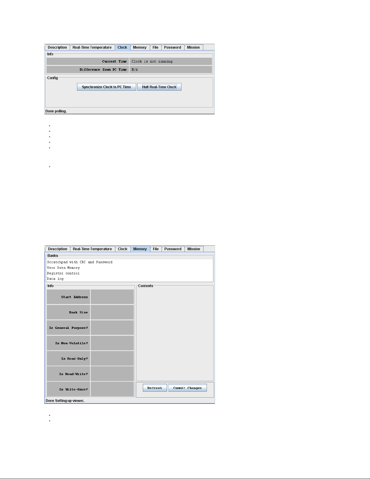
When the Clock tab is active, the Clock viewer:
Page 15 of 21
Continuously reads the time registers of the selected device.
Converts the reading from the device- specific format into a conventional format.
Displays the time read from the device (automatically updated with every reading).
Allows the RTC oscillator to be stopped and restarted.
Allows the time/date of the computer (PC or workstation) to be copied to the time registers in the device (i.e., click on Synchronize Clock to PC Time); this
function also restarts a halted RTC oscillator.
Notes:
If the 1-Wire device uses a binary counter as RTC (e. g., the DS1904, DS2415, DS2417), the Clock viewer sets the device clock to UTC (also known as
Greenwich Mean Time, GMT). If the RTC of the 1- Wire device counts seconds, hours, days, months, and years in separate registers (e.g., the DS1921,
DS1922), the Clock viewer sets the device clock to the local time.
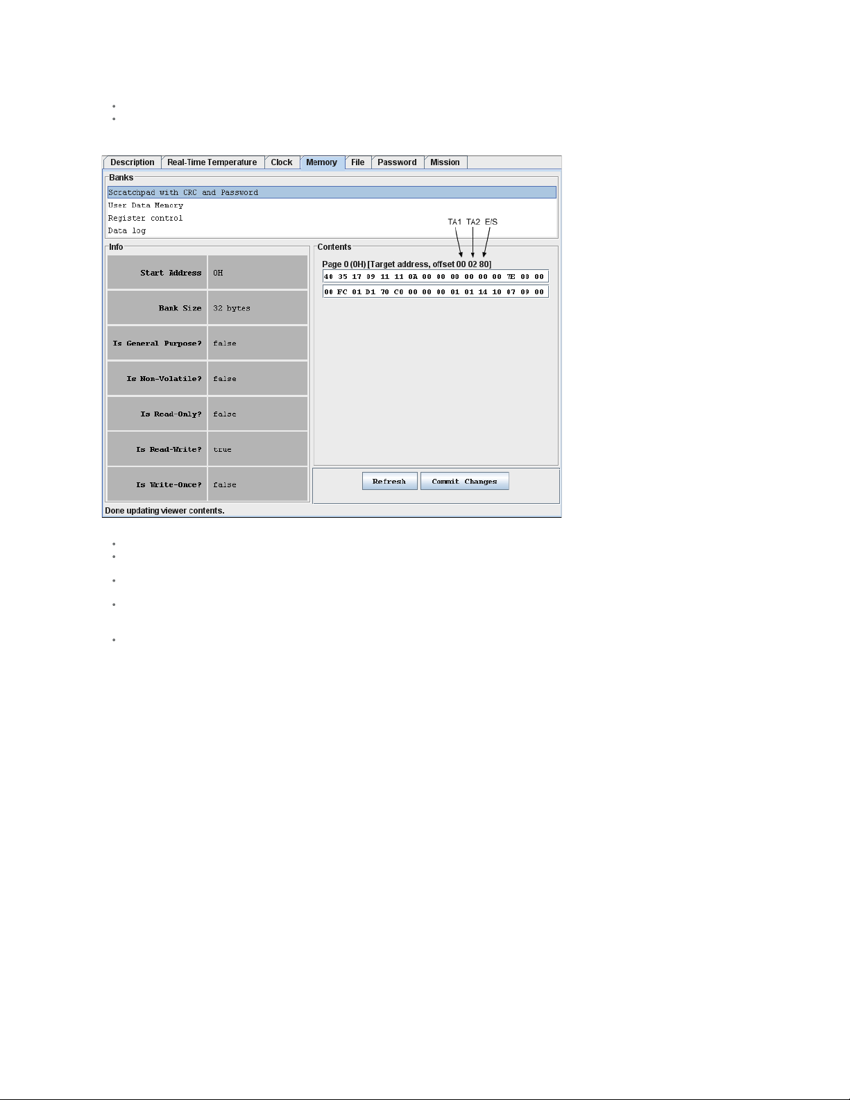
Memory
The Memory viewer displays in hexadecimal format the data of the selected memory bank of the selected 1-Wire memory device connected to the OneWireViewer.
The user can change the data (see Hex Editor below) and write it back to the 1-Wire device.
The tab of the Memory viewer consists of three areas: Banks (top), Info (bottom left), and Contents (center right). Two buttons below the Contents area allow the
data of a selected memory bank to be reread (Refresh) and data that was manually entered in the contents area to be written to the 1-Wire device ( Commit
Changes). Depending on the size of the tab area, there may be scroll bars for the Info and Contents area. The Memory viewer applies to all devices that contain
general-purpose user memory and/or special function/register pages. See the Supported Devices table above for the list of devices. A memory bank must first be
selected before its data (Contents) and characteristics (Info) will be displayed. The Contents area is automatically refreshed whenever the bank selection changes.
Sample Memory Tab (DS1922L)
When the Memory tab is active, the Memory viewer:
Lists the names of the available banks.
Displays the characteristics and contents of the selected bank.
Page 16
Allows the contents of the selected bank to be changed.
Allows the new data to be copied to the selected bank.
Page 16 of 21
Sample Memory Tab with Scratchpad Selected
Notes:
The number of the memory banks and their respective names depend on the type of the device viewed.
The display format in the content field varies with the device and memory bank selected. For most devices there are 2 x 16 bytes per page. With EPROM
devices, there are n x 8 bytes (special function registers only). With the DS1977 the format is 2 x 32 bytes per page.
If the selected memory bank is a scratchpad, the target address TA1, TA2, and the E/S byte (offset) are displayed above the scratchpad contents. With other
memory banks and depending on the device, one will see device- specific information associated with a memory page.
To write to the device, select the bytes to be changed in the Contents field, type new data, and click on Commit Changes. This method applies to all memory
blocks shown in the Memory tab. The viewer will perform the necessary steps (e.g., write scratchpad, copy scratchpad) to update the device memory or
register. See the section Auxiliary Functions text editor (hex/ASCII editor) for more details.
Writing to an EPROM device requires a port adapter that supports 12V programming pulses.
File
The File viewer displays the file names and directory structure of the selected 1-Wire memory device connected to the OneWireViewer. The user can format the
device, create/delete directories and files, edit files (see Hex Editor and ASCII Editor), resize files, and write them back to the 1-Wire device.
The File viewer supports the 1-Wire File Structure. (See application note 114, "1-Wire File Structure.") The tab of the File viewer consists of two areas: Directory
(center left), and File Contents (center right). In addition, there are eight command buttons. The vertical bar between Directory and File Contents can be moved
horizontally to change the size of the areas. Depending on the size of the file tab, there may be scroll bars for the Directory and File Contents area. The File viewer
applies to all devices that contain general-purpose user memory. See the Supported Devices table above for the list of devices.
Page 17
Sample File Tab (DS1922L)
Page 17 of 21
File Viewer Commands
Format Device (to create a root directory in the device)
The device must be formatted before files can be created. See application note 114 (cited above) for additional information. Formatting does not erase the memory.
Data from previous sessions will eventually be overwritten.
Create New Directory (to create a file directory or subdirectory)
Directory names are up to four ASCII characters long.
Create New File (to create a file in the device)
File names are up to four ASCII characters plus a numeric extension in the range from 0 to 99. Certain extensions are reserved for special purposes, e.g., 100 for
Append Files (EPROM devices only). (For more information see Table 1 in application note 114, "1 -Wire File Structure.")
Delete Selected (to delete a file or directory)
This function deletes the entry of the file in the directory or removes a subdirectory. It does not erase the file contents. However, with the file entry or subdirectory
removed, the file is no longer accessible through the File viewer. The file data can be recovered on the byte level through the Memory viewer (see above).
Read Dir (to read the device directory)
Displays file and directory names.
Read File (to read and display the contents of the selected file)
The file contents can be viewed as data bytes or as text. Click on the Hex or Ascii tab to change the view.
Write File (to write changes to the device)
This function assumes that the size of the file has not changed. If the file size has changed, first use Resize File to specify the new file length. Write File includes
an automatic readback for verification.
Resize File (to change the size of a file)
This function allows specification of the number of bytes that will be used for the file. If the new size is lower than the number of characters (bytes) in the content
area, the data will be truncated at the end. If the new size is too large, 00h bytes will be appended at the end of the file. A file first needs to be read before it can
be resized.
When the File tab is active, the File viewer:
Provides access to various file and directory functions.
Allows a file to be selected or a directory to be opened.
Allows the file's contents and size to be changed.
Allows the new contents to be written to the device.
Page 18

Sample File Tab with Directory and File Data Displayed
Page 18 of 21
Notes:
The 1-Wire File Structure allows multiple devices to be formatted as one cluster. For this reason when formatting a device, the device needs to be selected
again, even if the File viewer already accesses it.
Before data can be written to a file, the file must first be created as a new file.
The file size is a multiple of 28 bytes (59 bytes with the DS1977). Changing the file size through Resize File automatically updates the file size in the display's
directory area. Changing the file size to 0 bytes is equivalent to first deleting and then creating the same file again.
A new file is filled with 00h bytes and has a size of 28 bytes (59 bytes with the DS1977).
To create a file inside a directory, first click on the directory and then use the Create New File function.
To change the contents of a file (hex as well as ASCII format), select the section (bytes/characters) to be changed, type the new contents, and click on Write
File. If the file is edited on the ASCII tab, there will be an automatic resize when the file is written back to the device. See Auxiliary Functions , and sections
Hex Editor with File Viewer and ASCII Editor for more details.
Writing to an EPROM device requires a port adapter that supports 12V programming pulses.
When accessing another device, the file contents area still shows data from the most recently accessed file.
To copy data from a disk file to the File viewer and vice versa, use the editing, copy, and paste functions of the operating system.
Auxiliary Functions
Hex Editor
The Memory viewer allows the user to enter data in hex format. The File viewer expects hex input when the Hex tab is selected. There are three ways to use the
hex editor:
1. Change: select one or more bytes and replace them with the same number of new bytes.
2. Delete: select one or more bytes and delete them.
3. Insert: position the cursor between bytes in the contents field and enter one or more bytes.
With special function registers or EPROM devices one should only change (overwrite) bytes, but not insert or delete bytes.
Hex Editor with Memory Viewer
Editing
area
Changing
data
Deleting
data
Inserting
data
Verifying
data
Error
handling
All fields with white background that are displayed in the Contents area of the viewer. Each field is treated as an independent entity. More than
one field can be updated before committing the changes.
Using the cursor, select a range of adjacent bytes in the editing area and type as many new bytes as are selected. Entering data overwrites the
selected range and changes the background color of the field to yellow. When finished, click on Commit Changes.
Using the cursor, select one or more adjacent bytes in the editing area and press the "delete" key on the keyboard. This removes as many
bytes as are selected in the editing area and changes the background color of the affected field to yellow. When finished, click on Commit
Changes. The viewer will ask for permission to pad the affected field(s) in the editing area with 00h bytes. This padding, however, does not
happen and data at the end of the affected field(s) remains unchanged. All other data in the field(s) is shifted to the left (lower address)
according to the number of bytes deleted.
Position the cursor in a field of the editing area and type the data to be inserted. This changes the background color of the field to yellow and
shifts existing data to the right of the cursor out of the field, where it is lost. When finished, click on Commit Changes.
Click the Refresh button and scroll to the updated field in the editing area.
Numbers from 0 to 9 and characters (upper/lower case) from A to F are accepted. Other characters can be entered in the editing area, but are
not written to the device. Spaces are optional between bytes; they are taken as delimiters.
Page 19

Hex Editor with File Viewer
Page 19 of 21
Editing
Area
Changing
data
Deleting
data
Inserting
data
Verifying
data
Error
handling
ASCII Editor (File Viewer Only)
Editing
area
Changing
data
Deleting
data
Inserting
data
Verifying
data
Error
handling
Multiple rows of 16 bytes each in the Hex tab of the viewer; the last row can be shorter (partially editable). Each row is treated as an
independent entity. More than one row can be updated before committing the changes. Use the Resize button to set the size of the editing
area, as needed. The description below assumes that the editing area contains data, which was obtained by selecting a file in the directory area
and then clicking the Read File button.
Using the cursor, select a range of adjacent bytes in the editing area and type as many new bytes as are selected. Entering data overwrites the
selected range and changes the background color of the row to yellow. When finished, click on Write File.
Using the cursor, select one or more adjacent bytes in the editing area and press the "delete" key on the keyboard. This removes as many
bytes as are selected in the editing area and changes the background color of the affected field to yellow. When finished, click on Write File.
There is no padding at the end, and data deleted at the end remains unchanged. All other data in the row(s) is shifted to the left (lower
address) according to the number of bytes deleted.
Position the cursor in a row of the editing area and type the data to be inserted. This changes the background color of the field to yellow and
shifts existing data to the right of the cursor out of the row, where it is lost. When finished, click on Write File.
After writing, the file is automatically read back and its data is displayed.
Numbers from 0 to 9 and characters (upper/lower case) from A to F are accepted. Other characters can be entered in the editing area, but an
error message appears if there is an attempt to write the file to the device. Spaces are optional between bytes; they are taken as delimiters.
This is a large blank field in the ASCII tab of the viewer. The size of the file can be changed using the Resize button. The description below
assumes that the editing area is filled with "blanks" or contains data, which was obtained by selecting a file in the directory area and then
clicking Read File.
Using the cursor, select a range of adjacent characters in the editing area and type as many new characters as are selected. Entering data
overwrites the selected range. When finished, click Write File.
Using the cursor, select one or more adjacent characters in the editing area and press the "delete" key on the keyboard. This removes as many
characters as are selected in the editing area. When finished, click on Write File. Instead of padding at the end, the file is automatically resized.
Position the cursor in the editing area and type the text to be inserted. No text is deleted. When finished, click on Write File. The file is
automatically resized.
After writing, the file is automatically read back and its data is displayed.
All characters are accepted, including those that are not found on the English keyboard.
Appendix A. 1-Wire Port Adapters
The following table lists the 1- Wire adapters that the OneWireViewer supports. The name shown in the Short Reference column is used to identify a category of
adapter during the program setup. The DS9097E is a legacy adapter that relies on the bit timing of the UART that is controlling the COM port. This method is
described in application note 214, "Using a UART to Implement a 1-Wire Bus Master."
1- Wire Port Adapter Table
Port Type Short Reference Ordering Part Number Extended Features
DS9097U-009#
COM DS9097U
COM DS9097U DS9097U-E25# Overdrive, power delivery, EPROM programming (12V)
COM DS9097E* DS9097E# EPROM programming (12V)
COM DS9097E*
USB DS9490
USB DS9481R DS9481R-3C7+ Overdrive, power delivery, EPROM programming (12V, 7V)
*Not recommended for new designs.
Extended Features
Overdrive
The standard 1-Wire data rate is 15.3kbps. All iButtons and 1-Wire devices support this communication speed. Most 1-Wire devices also support overdrive speed,
which is typically 125kbps.
Power Delivery
Most iButtons and 1 -Wire devices are parasite powered. This means that they derive their operating energy from the 1-Wire net during communication. Some
devices, however, require more energy than can be accumulated in this fashion. For these devices, choose an adapter with the power- delivery feature.
DS9097U-S09#
DS1411-009#
DS1411-S09#
DS9097#
DS1413#
DS9490B#
DS9490R#
Overdrive, power delivery, built - in serial number (009 - suffix only)
None
Overdrive, power delivery, built - in serial number
Page 20
EPROM Programming
Page 20 of 21
iButton and 1 -Wire devices that are one -time-programmable (OTP) incorporate technology called electrically programmable read only memory (EPROM). EPROM
programming requires 12V programming for writing. Although all adapters can read an EPROM i
to them.
Button, only adapters with EPROM programming capability can write
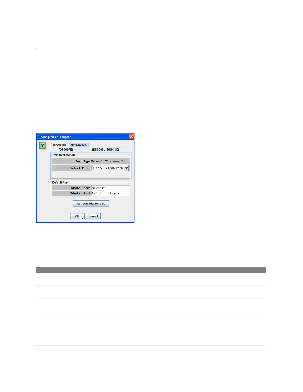
NetAdapter
The NetAdapter is a virtualized 1 - Wire adapter. Using TCP/IP protocol, it is possible for the OneWireViewer to communicate through a 1-Wire adapter attached to
another PC, as long as both PCs are connected through a TCP/IP network. Another requirement is that the other PC must be running a small host program, such
as the "StartNetAdapterHost" demo program found in the 1-Wire API for Java Software Development Kit. It is recommended that suitable software drivers for the 1 Wire adapter be installed on the host PC, such as the 1-Wire Drivers . For a more in -depth discussion on this, please see application note 193, "Extending 1 -Wire
Range with Network Proxies."
On the host PC where the 1-Wire adapter of interest resides, the StartNetAdapterHost Java program should be run from a command line. This is done by simply
copying the program and the OneWireAPI.jar file to a directory and typing the following example command-line parameters:
java -cp .;OneWireAPI.jar StartNetAdapterHost -adapterName {DS9490} - adapterPort USB1 -listenPort 6161 -secret secret
This sets up the host program to communicate to a DS9490 on USB1 and allows NetAdapter connections to it through the TCP/IP port of 6161 with the secret set to
"secret". Then, on the client OneWireViewer, simply set up the NetAdapter as shown in the screen shot below. In the "Adapter Name" field, type in "NetAdapter". In
the "Adapter Port" field, type in the IP address of the host computer, the TCP/IP socket port number, and the secret separated by colons.
Example "Pick Adapter" Window
1- Wire is a registered trademark of Maxim Integrated Products, Inc.
iButton is a registered trademark of Maxim Integrated Products, Inc.
Excel is a registered trademark of Microsoft Corporation.
Hygrochron is a trademark of Maxim Integrated Products, Inc.
Java is a registered trademark and registered service mark of Oracle and/or its affiliates.
Thermochron is a registered trademark of Maxim Integrated Products, Inc.
Related Parts
DS1411 Serial Port iButton Holder
DS2480B Serial to 1
DS2490 USB to 1
DS9097U-009 Universal
DS9097U-E25 Universal
DS9097U-S09 Universal 1-Wire COM Port Adapter
DS9490 USB to 1
More Information
For Technical
For Samples:
Other Questions
Support: http://www.maximintegrated.com/support
http://www.maximintegrated.com/samples
and Comments:
http://www.maximintegrated.com/contact
-Wire Line Driver Free Samples
-Wire Bridge Chip
1- Wire COM Port Adapter
1- Wire COM Port Adapter
Button Adapter
-Wire/i
Page 21

Application Note 3358: http://www.maximintegrated.com/an3358
USER GUIDE 3358, AN3358, AN 3358, APP3358, Appnote3358, Appnote 3358
Page 21 of 21
Copyright © by Maxim Integrated
Additional Legal Notices:
http://www.maximintegrated.com/legal
 Loading...