

Page 1

MAXQ20-Based Microcontrolle r
Bootloader Command Reference
Rev 1; 9/13
Maxim Integrated cannot assume responsibility for use of any circuitry other than circuitry entirely embodied in a Maxim Integrated product. No circuit patent
licenses are implied. Maxim Integrated reserves the right to change the circuitry and specifications without notice at any time.
Maxim Integrated 160 Rio Robles, San Jose, CA 95134 USA 1-408-601-1000
© 2013 Maxim Integrated Products, Inc. Maxim Integrated and the Maxim Integrated logo are trademarks of Maxim Integrated Products, Inc.
Page 2

MAXQ20-Based Microcontroller Bootloader Command Reference
The MAXQ20 microcontroller core used in many of Maxim’s products employs a firmware bootloader accessible
through the programming interface. The command set used by the bootloader is common across all MAXQ20core devices, with additional commands supporting unique features of specific devices. By taking advantage of
this commonality, the developer of a host-side programming interface can reuse existing software when adding
programming support for new devices. This document describes the command set used by the MAXQ20-core
microcontrollers.
Overview
All Maxim microcontrollers with a MAXQ20 core share a common bootloader protocol to maximize software reuse
and minimize the development cycle required to add programming support for new Maxim MAXQ20-core
microcontrollers.
This document lists the commands supported by the MAXQ20-core bootloaders. Not all commands are supported
in all devices; details about the bootloader commands specific to each device will be described in the applicable
user’s guide. The Get Support Commands command can also be used to determine which families of commands
are supported Commands in families 0-E are function the same across all products, but not all commands are
supported in all devices.
All devices with more than 64KB of flash memory must utilize the word mode version of commands which offer a
byte/word mode choice. Use the Get Code Size command or consult the applicable user’s guide to determine the
amount of code memory a device.
2
Page 3
MAXQ20-Based Microcontroller Bootloader Command Reference
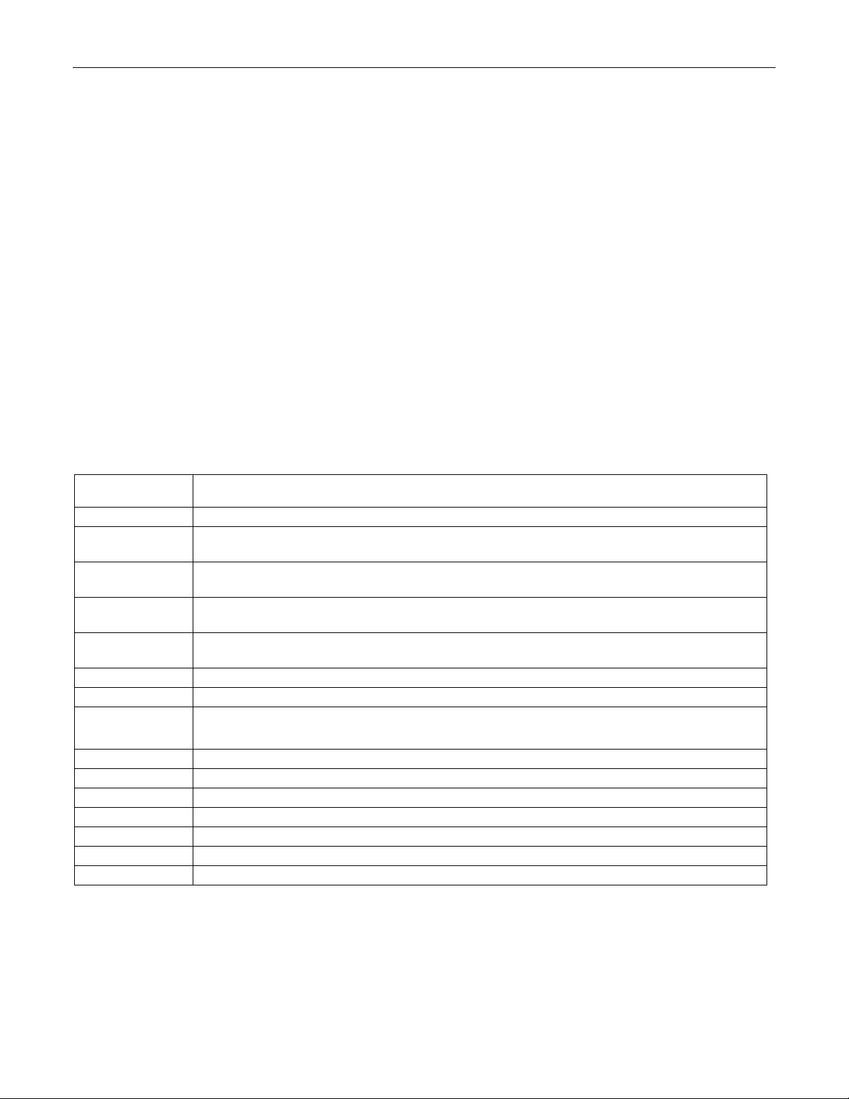
STATUS
VALUE
00
No Error. The last command completed successfully .
Family Not Supported. An attempt was made to use a command f rom a family which the
bootloader does not support.
Invalid Command. An attempt was made to use a nonexistent command within a
supported command family.
No Password Match. This status code is returned when an attempt is made to use a
command other than a Family 0 command when the sec uri ty lock is set (SL=1).
Bad Parameter. The parameter (address or otherwise) passed to the command was out of
range or otherwise invalid.
05
Verify Failed. The verification step failed on a Load/Verify or Verif y command.
06
Unknown Register. An attempt was made to read from or write to a nonexistent register.
08
Master Erase Failed. The bootloader was unable t o perform master erase.
09
Page Erase Failed. An attempt to erase a flash page failed.
10
Not Implemented. The command or feature was not implemented.
11
Timeout. A hardware timeout occurred during the operation.
12
Invalid Mode.
13
Hardware Failure.
14
Loader Lock Failed. Writing the loader lockout pattern t o flash failed.
Loader Protocol Layer
Bootloader commands are segregated by command family, designated. 0 to F. Commands within a family have a
common functionality. Family F comman ds are target-specific that have special features in common.
All bootloader commands begin with a single command byte. The high four bits of this command byte define the
command family (from 0 to 15), while the low fou r bits define the specific command within that family.
After each command has completed, the loader will output a ‘prompt’ byte to indicate that it has finished the
operation. The prompt byte is the single character ‘>’ (byte value 03Eh).
After each bootloader command the error code should be read by means of the Get Status command (04h). If the
status byte is a value other than 00h then an error has occurred and the host should take the appropriate action.
All commands in Family 0 may be executed whether or not the security lock is set or password protection
enabled. All other commands may only be executed if the security lock is cleared (SL=0).
When providing addresses for code or data read or write to bootloader commands, all addresses run from 0000h
to (memory size – 1).
Table 1. Bootloader Status Codes
01
02
03
04
07
MEANING
Word Mode Not Supported. An attempt was made to set word mode access, but the
bootloader supports byte mode access only.
3
Page 4
MAXQ20-Based Microcontroller Bootloader Command Reference
Byte1
Input
00h
Output
03Eh
Byte1
Byte2
Input
01h
00h
Output
03Eh
Byte1
Byte2
Byte3
Input
02h
00h
00h
Output
03Eh
00h
03Eh
Byte1
Bytes 2 … 33
Byte 34
Byte 35
Input
03h
32-byte password value
00h
00h
Output
03Eh
Byte1
Byte2
Byte3
Byte4
Byte5
Input
04h
00h
00h
00h
00h
Output
Flags
Status Code
03Eh
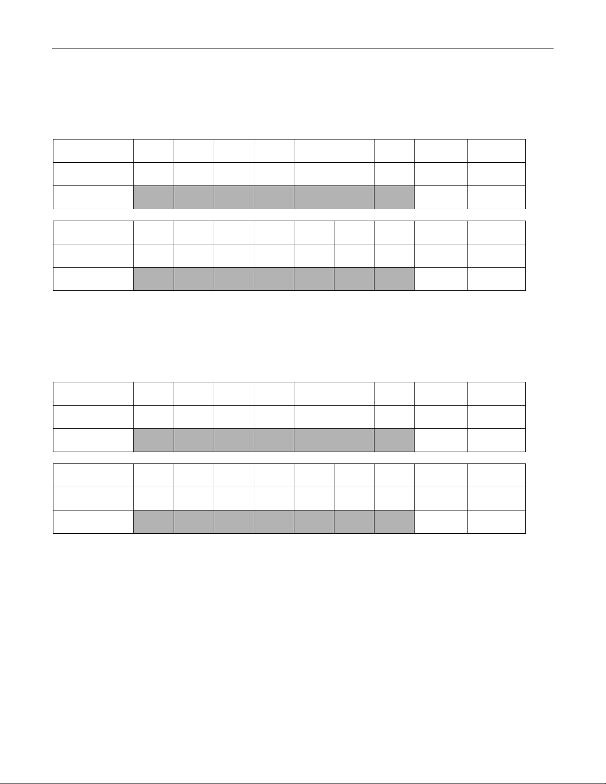
Family 0 Commands (Always Available)
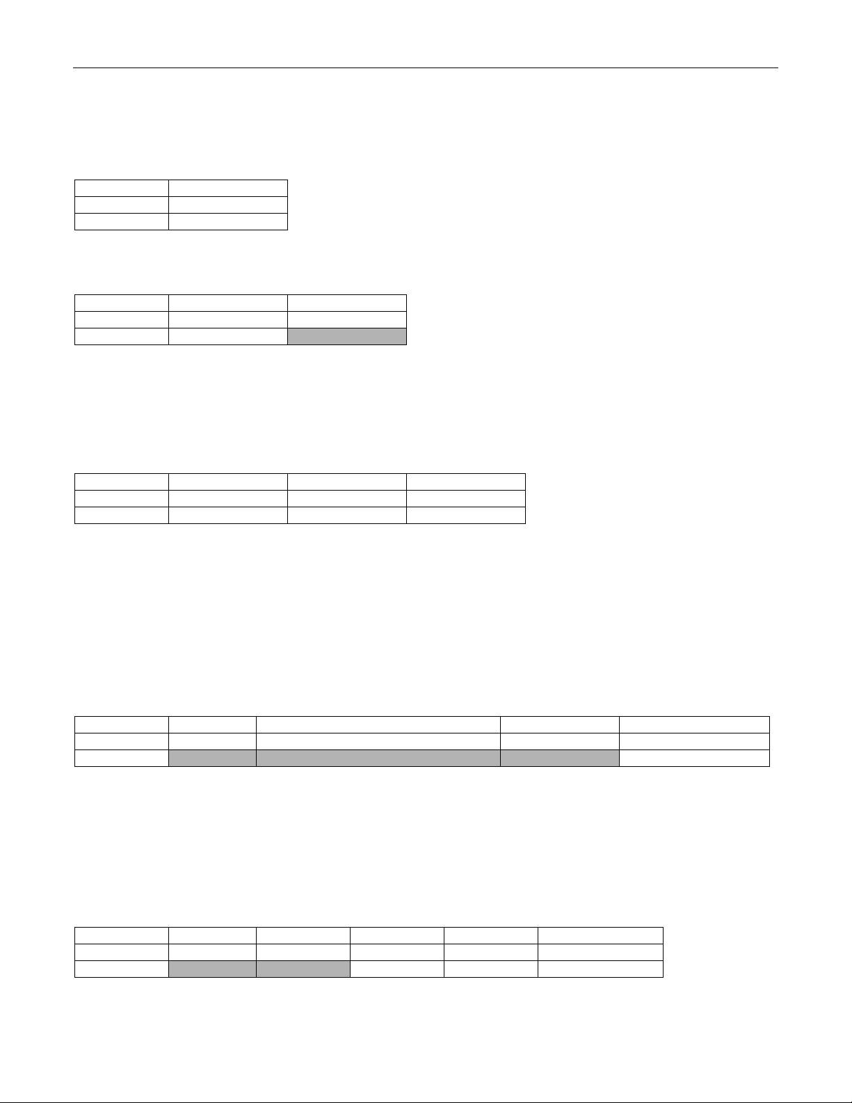
Command 00h—No Operation
Command 01h—Exit Loader
This command causes the bootloader command loop to exit. Upon exit, the SPE bit is cleared and the device
performs and internal reset. Following the reset, execution jumps to the beginning of application code at address
0000h.
Command 02h—Master Erase
This command erases (programs to FFFFh) all words in the program flash memory and writes all words in the
data SRAM and the AES cryptographic memory to zero. After this command completes, if SL=1 the security lock
bit is automatically cleared and the device res ets, but the device will still remain in loader mode.
Devices which support the Set Context command require the desired context to be set before executing this
command. The selected context will designate which area(s) (system, user loader, or user application) will be
erased.
Command 03h—Password Match
This command is used to gain access to memory on devices protected by the 32-byte password match f eature.
Devices which support the Set Context command require the desired context to be set before executing this
command. The selected context will designate which area (system, user loader, or user application) the password
will be compared against.
Command 04h—Get Status
The status code returned by this command is defined in Table 1. The flags byte contains the bit status flags
shown in Table 2.
4
Page 5
FLAG BIT
MEANING
Password Lock.
001Fh) required to allow access to the bootloader and in-circuit debugging functions.
3:8
Reserved.
Byte1
Byte2
Byte3
Byte4
Byte5
Byte6
Byte7
Input
05h
00h
00h
00h
00h
00h
00h
Output
SupportL
SupportH
CodeLen
DataLen
03Eh
Byte1
Byte2
Byte3
Byte4
Byte5
Input
06h
00h
00h
00h
00h
Output
SizeL
SizeH
03Eh
Byte1
Byte2
Byte3
Byte4
Byte5
Input
07h
00h
00h
00h
00h
Output
SizeL
SizeH
03Eh
Table 2. Bootloader Status Flags
MAXQ20-Based Microcontroller Bootloader Command Reference
0
0 – Password protection of bootloader and debugging functions is disabled.
1 – 32-byte password match against a stored pass word (in program space words 0010h–
Word/Byte Mode.
1
0 – The bootloader is currently in byte mode for memory reads/writes.
1 – The bootloader is currently in word mode for memory reads/writes.
Word/Byte Mode Supported.
2
0 – The bootloader supports byte mode only .
1 – The bootloader supports word mode as well a s byte mode.
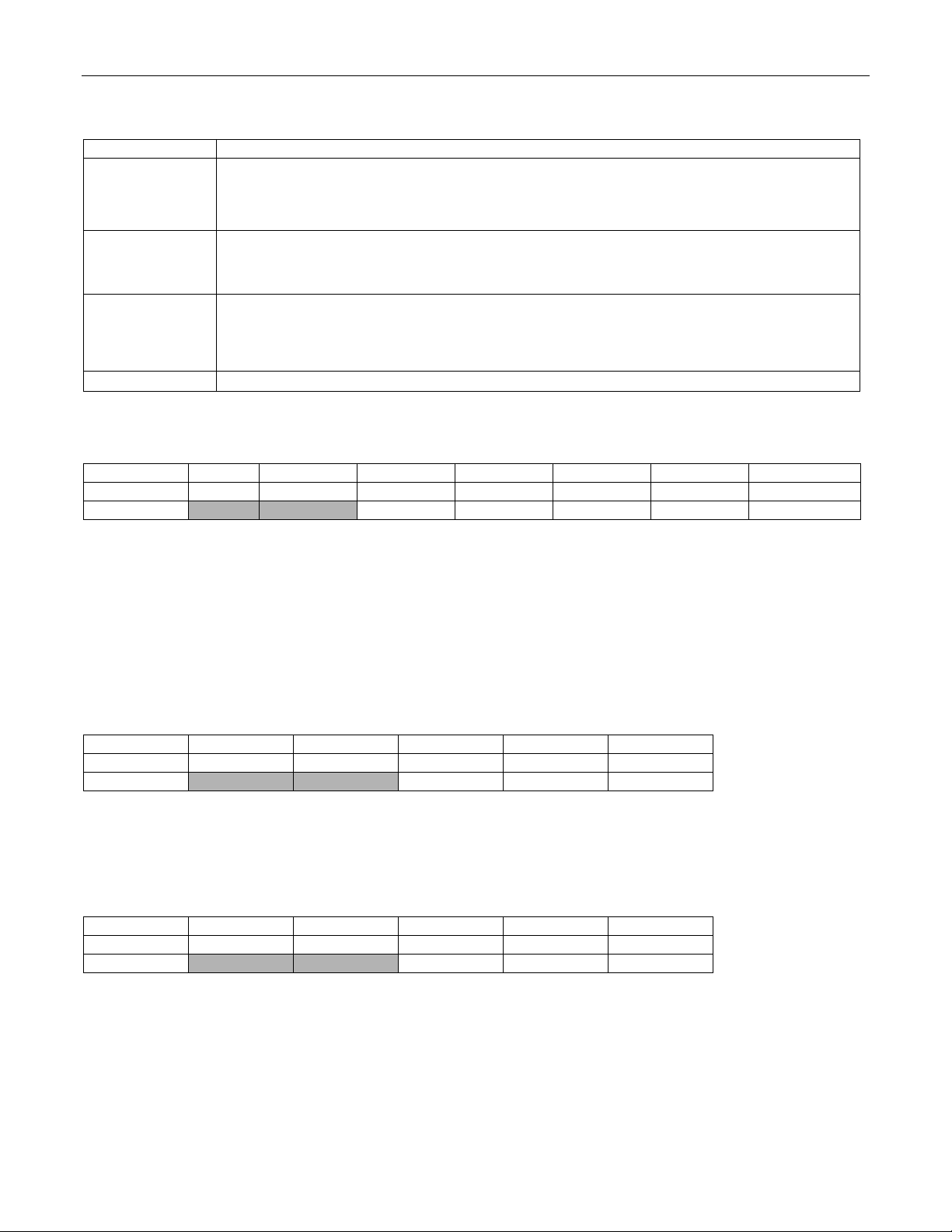
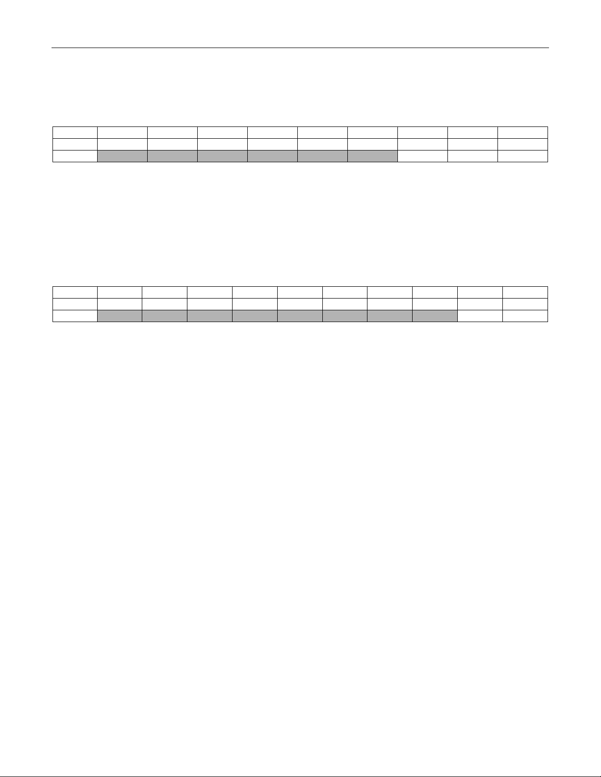
Command 05h—Get Supported Commands
The SupportL (LSB) and SupportH (MSB) bytes form a 16-bit value indicates which command families this
bootloader supports. If bit 0 is set to 1, it indicates that Family 0 is supported. If bit 1 is set to 1, it indicates that
Family 1 is supported, and so on.
The CodeLen and DataLen bytes return the fixed block lengths used by the Load/Dump/Verify Fixed Length
commands for code and data space, respectively. Devices which do not support fixed block loading will return 00h
for bytes five and six.
Command 06h—Get Code Size
This command returns SizeH:SizeL, which represents the size of available code memory in words minus 1. If this
command is unsupported, the return value will be 0000h meaning “unknown amount of memory ”.
Command 07h—Get Data Size
This command returns SizeH:SizeL, which represents the size of available data memory in words minus 1. If this
command is unsupported, the return value will be 0000h meaning “unknown amount of memory”.
5
Page 6
MAXQ20-Based Microcontroller Bootloader Command Reference
Byte1
Byte2
Byte3
Byte4
Byte5
Input
08h
00h
00h
00h
00h
Output
VersionL
VersionH
03Eh
Byte1
Byte2
Byte3
Byte4
Byte5
Input
09h
00h
00h
00h
00h
Output
VersionL
VersionH
03Eh
Byte1
Byte2
Byte3
Byte4
Input
0Ah
Mode
00h
00h
Output 03Eh
Byte1
Byte2
(Variable)
Last Byte
Input
0Dh
0Dh
00h, 00h, 00h, ....
00h
Output
Device dependent information
03Eh
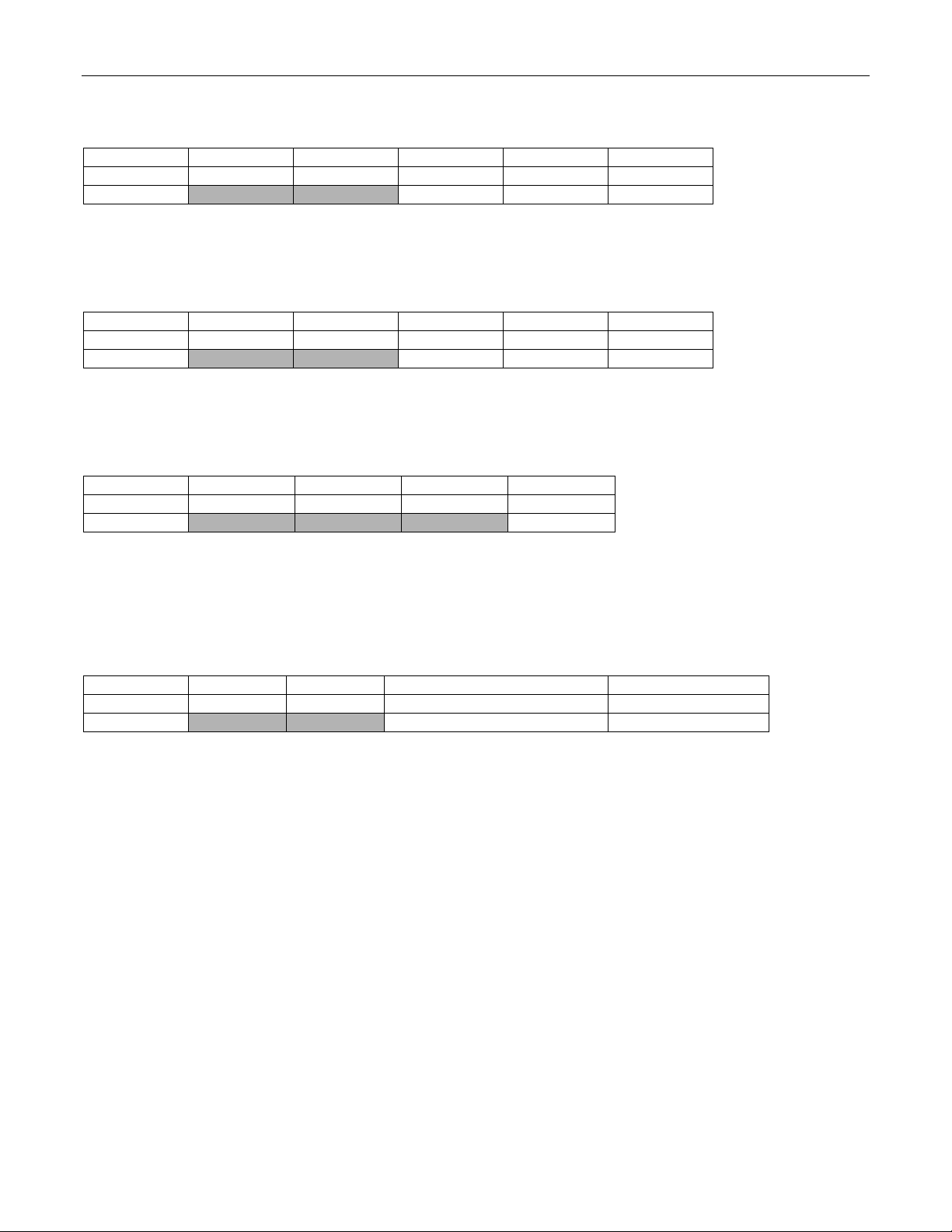
Command 08h—Get Loader Version
This is a factory verification command and is in cluded here only for completeness.
Command 09h—Get Utility ROM Version
This is a factory verification command and is in cluded here only for completeness.
Command 0Ah—Set Word/Byte Mode Access
The Mode byte should be 0 to set byte access mode or 1 to set word access mode. The current access mode is
returned in the status flag byte by command 04h, as well as a flag to indicate whether word access mode is
supported by this particular bootloader.
Command 0Dh—Get ID Information
The output of this command is a zero-terminated ASCII string. Devices which support this command will have a
detailed description in the applicable user’s gui de.
6
Page 7

MAXQ20-Based Microcontroller Bootloader Command Reference
(Length)
Bytes
Byte
Length+5
Byte
Length+6
Input
10h
Length
AddrL
AddrH
Data to load
00h
00h
Output
03Eh
(Length)
Bytes
Byte
Length+5
Byte
Length+6
Input
11h
Length
AddrL
AddrH
Data to load
00h
00h
Output
03Eh
Family 1 Commands—Load Variable Lengt h
Command 10h—Load Code Variable Length
Byte1 Byte2 Byte3 Byte4
This command programs (Length) bytes of data into the program flash starting at byte address (AddrH:AddrL),
with the following restrictions.
• The low bit of the AddrL is always forced to zero, since instructions in program flash must be word
aligned.
• In byte mode, if an odd number of bytes is input, the final word written to the program flash will have its
most significant byte set to 00h by default.
• Memory locations in flash which have previously been loaded must be erased using the Master Erase or
Erase Code Fixed Length commands before they can be loaded with a different value.
• In keeping with standard MAXQ little-endian memory architecture, the least significant byte of each word
is loaded first. For example, loading bytes (11h, 22h, 33h, 44h) starting at address 0000h, the first two
words of program space will be written to (2211h, 4433h).
Command 11h—Load Data Variable Length
Byte1 Byte2 Byte3 Byte4
This command writes (Length) bytes of dat a i nto the data SRAM starting at byte address (AddrH:AddrL).
7
Page 8
MAXQ20-Based Microcontroller Bootloader Command Reference
(Length)
Bytes
Byte
Length+7
Input (to dump
< 256 units)
Output
Memory
contents
(Length)
Bytes
Byte
Length+8
Input (to dump
256+ units)
Output
Memory
contents
(Length)
Bytes
Byte
Length+7
Input (to dump
< 256 units)
Output
Memory
contents
(Length)
Bytes
Byte
Length+8
Input (to dump
256+ units)
Output
Memory
contents
Family 2 Commands—Dump Variabl e Length
Command 20h—Dump Code Variable Length
Byte1 Byte2 Byte3 Byte4 Byte5 Byte6
20h 1 AddrL AddrH Length 00h 00h... 00h
Byte1 Byte2 Byte3 Byte4 Byte5 Byte6 Byte7
20h 2 AddrL AddrH LenL LenH 00h 00h... 00h
This command has a slightly different format depending on the length of the dump requested. It returns the
contents of the program flash memory – (Length) or (LenH:LenL) bytes starting at byte address (AddrH:AddrL).
“Units” is either bytes or words, depending on which mode is currently selected.
Command 21h—Dump Data Variable Length
Byte1 Byte2 Byte3 Byte4 Byte5 Byte6
21h 1 AddrL AddrH Length 00h 00h... 00h
Byte1 Byte2 Byte3 Byte4 Byte5 Byte6 Byte7
03Eh
03Eh
03Eh
This command has a slightly different format depending on the length of the dump requested. It returns the
contents of the data SRAM – (Length) or (LenH:LenL) bytes starting at byte address (AddrH:AddrL). “Units ” is
either bytes or words, depending on which mode is currently selected.
8
21h 2 AddrL AddrH LenL LenH 00h 00h... 00h
03Eh
Page 9

MAXQ20-Based Microcontroller Bootloader Command Reference
Byte9
Input
< 256 units)
Output
CrcH
CrcL
03Eh
Byte1
Byte2
Byte3
Byte4
Byte5
Byte6
Byte7
Byte8
Byte9
Byte10
Input
256+ units)
Output
CrcH
CrcL
03Eh
Byte9
Input
< 256 units)
Output
CrcH
CrcL
03Eh
Byte1
Byte2
Byte3
Byte4
Byte5
Byte6
Byte7
Byte8
Byte9
Byte10
Input
256+ units)
Output
CrcH
CrcL
03Eh
Family 3 Commands—CRC Variable Length
Command 30h—CRC Code Variable Length
Byte1 Byte2 Byte3 Byte4 Byte5 Byte6 Byte7 Byte8
(to CRC
(to CRC
This command has a slightly different format depending on the length of the CRC requested. It returns the CRC16 value (CrcH:CrcL) of the program flash – (Length) or (LenH:LenL) bytes/words starting at (AddrH:AddrL).
“Units” is either bytes or words, depending on which mode is currently selected.
Command 31h—CRC Data Variable Length
(to CRC
30h 1 AddrL AddrH
30h 2 AddrL AddrH LenL LenH 00h 00h 00h 00h
Byte1 Byte2 Byte3 Byte4 Byte5 Byte6 Byte7 Byte8
31h 1 AddrL AddrH Length 00h 00h 00h 00h
Lengt
h
00h 00h 00h 00h
(to CRC
This command has a slightly different format depending on the length of the CRC requested. It returns the CRC16 value (CrcH:CrcL) of the data SRAM – (Length) or (LenH:LenL) bytes/words starting at (AddrH:AddrL). “Units”
is either bytes or words, depending on which mod e i s cu rrently selected.
9
31h 2 AddrL AddrH LenL LenH 00h 00h 00h 00h
Page 10

MAXQ20-Based Microcontroller Bootloader Command Reference
(Length)
Bytes
Byte
Length+5
Byte
Length+6
Input
40h
Length
AddrL
AddrH
Data to verify
00h
00h
Output
03Eh
(Length)
Bytes
Byte
Length+5
Byte
Length+6
Input
41h
Length
AddrL
AddrH
Data to verify
00h
00h
Output
03Eh
Family 4 Commands—Verify Variable Length
Command 40h—Verify Code Variable Length
Byte1 Byte2 Byte3 Byte4
This command operates in the same manner as the “Load Code Variable Length” command, except that instead
of programming the input data into flash memory, it verifies that the input data matches the data already in code
space. If the data does not match, the stat us code is set to reflect this failure.
The Get Status command must be executed after any verify command to determine if the verify was successful.
Command 41h—Verify Data Variable Length
Byte1 Byte2 Byte3 Byte4
This command operates in the same manner as the “Load Data Variable Length” command, except that instead
of writing the input data into data SRAM, it verifies that the input data matches the data already in data space. If
the data does not match, the status code is set to reflect this failure.
The Get Status command must be executed af ter any verify command to determine if the verify was successful.
10
Page 11

MAXQ20-Based Microcontroller Bootloader Command Reference
(Length)
Bytes
Byte
Length+5
Byte
Length+6
Input
50h
Length
AddrL
AddrH
Data to load
and verify
00h
00h
Output
03Eh
(Length)
Bytes
Byte
Length+5
Byte
Length+6
Input
51h
Length
AddrL
AddrH
Data to load
and verify
00h
00h
Output
03Eh
Family 5 Commands—Load and Verify Variable Length
Command 50h—Load and Verify Code Variable Length
Byte1 Byte2 Byte3 Byte4
This command combines the functionality of the “Load Code Variable Length” and “Verify Code Variable Length”
commands. The Get Status command must be executed after any verify command to determine if the verify was
successful.
Command 51h—Load and Verify Data Variable Length
Byte1 Byte2 Byte3 Byte4
This command combines the functionality of the “Load Data Variable Length” and “Verify Data Variable Length”
commands. The Get Status command must be executed after any verify command to determine if the verify was
successful.
11
Page 12

MAXQ20-Based Microcontroller Bootloader Command Reference
Byte1
Byte2
Byte3
Byte4
Byte5
Bytex
Byte21
Byte22
Input
90h
CodeLen
AddrL
AddrH
Data1
Data(x-4)
00h
00h
Output 03Eh
Byte1
Byte2
Byte3
Byte4
Byte5
Byte6
Byte7
Byte8
Byte9
Byte10
Input
91h
DataLen
AddrL
AddrH
Data1
Data2
Data3
Data4
00h
00h
Output 03Eh
Family 9 Commands—Load Fixed Lengt h
Command 90h—Load Code Fixed Length
This command loads a block of 16 bytes into the program memory starting at the specified address. The address,
which must be from 0000h–07FFh, is rounded down to the nearest block boundary (multiple of 16) before the
data is loaded. CodeLen is one of the values retu rned by the Get Supported Commands command.
Command 91h—Load Data Fixed Length
This command is only useful in devices with nonvolatile data memory. This command loads a block of 4 bytes into
data memory starting at the specified address. The address, which must be from 0040h–00BFh, is rounded down
to the nearest block boundary (multiple of 4) before the data is loaded. DataLen is one of the values returned by
the Get Supported Commands command.
12
Page 13

MAXQ20-Based Microcontroller Bootloader Command Reference
Byte1
Byte2
Byte3
Byte4
Byte5
Byte6
Byte7
Byte8
Input
B0h
00h
00h
00h
00h
00h
00h
00h
Output
CRCL
CRCH
3Eh
Byte1
Byte2
Byte3
Byte4
Byte5
Byte6
Byte7
Byte8
Input
B1h
00h
00h
00h
00h
00h
00h
00h
Output
CRCL
CRCH
3Eh
Family B Commands—CRC Fixed Lengt h (Password Protected)
Command B0h—CRC Code Fixed Length
This command returns the CRC-16 value (CRCH:CRCL) of the entire program memory
Command B1h—CRC Data Fixed Length
This command is only useful in devices with nonvolatile data memory. This command returns the CRC-16 value
(CRCH to CRCL) of the entire data memory, excludin g the data SRAM.
13
Page 14
MAXQ20-Based Microcontroller Bootloader Command Reference
Byte1
Byte2
Byte3
Byte4
Byte5
Byte6-21
Byte22
Byte23
Byte24
Input
C0h
CodeLen
AddrL
AddrH
Data1
xx
Data16
00h
00h
Output
3Eh
Byte1
Byte2
Byte3
Byte4
Byte5
Byte6
Byte7
Byte8
Byte9
Byte10
Input
C1h
DataLen
AddrL
AddrH
Data1
Data2
Data3
Data4
00h
00h
Output 3Eh
Family C Commands—Verify Fixed Length
Command C0h—Verify Code Fixed Length
This command operates in the same manner as the “Load Code Fixed Length” command, except that instead of
programming the input data into flash memory, it verifies that the input data matches the data already in code
space. If the data does not match, the status code is set to reflect this failure. CodeLen is one of the values
returned by the Get Supported Commands command.
The Get Status command must be executed af ter any verify command to determine if the verify was successful.
Command C1h—Verify Data Fixed Length
This command operates in the same manner as the “Load Data Fixed Length” command, except that instead of
programming the input data into flash memory, it verifies that the input data matches the data already in data
space. If the data does not match, the status code is set to reflect this failure. DataLen is one of the values
returned by the Get Supported Commands command.
The Get Status command must be executed after any verify command to determine if the verify was successful.
14
Page 15

MAXQ20-Based Microcontroller Bootloader Command Reference
Byte1
Byte2
Byte3
Byte4
Byte5
Byte6-21
Byte22
Byte23
Byte24
Input
D0h
10h
AddrL
AddrH
Data1
xx
Data16
00h
00h
Output
3Eh
Byte1
Byte2
Byte3
Byte4
Byte5
Byte6
Byte7
Byte8
Byte9
Byte10
Input
D1h
04h
AddrL
AddrH
Data1
Data2
Data3
Data4
00h
00h
Output 3Eh
Family D Commands—Verify Fixed Length
Command D0h—Load/Verify Code Fixed Length
This command combines the functionality of the "Load Code Fixed Length" and "Verify Code Fixed Length"
commands
Command D1h—Load/Verify Data Fixed Length
This command is only useful in devices with nonvolatile data memory. This command combines the functionality
of the "Load Data Fixed Length" and "Verify Data Fi xed Length" commands.
15
Page 16

MAXQ20-Based Microcontroller Bootloader Command Reference
Byte1
Byte2
Byte3
Byte4
Byte5
Input
E0h
00h
AddrL
AddrH
00h
Output
03Eh
Family E Commands—Erase Fixed Length
Command E0h—Erase Code Fixed Length
This command erases (programs to FFFFh) all words in a 512-word page of the program flash memory. The
address given should be located in the 512-word page to be erased. For example, providing address 0000h (in
byte mode) to this command erases the first 512-word page, address 0400h erases the second page, and so on.
16
Page 17

MAXQ20-Based Microcontroller Bootloader Command Reference
Byte1
Byte2
Byte3
Input
F1h
00h
00h
Output
Context
03Eh
Byte1
Byte2
Byte3
Byte4
Byte5
Byte6
Input
F1h
50h
4Ch
4Ch
4Fh
00h
Output 03Eh
Byte1
Byte2
Byte3
Byte4
Input
F1h
Context
00h
00h
Output 03Eh
Byte1
Byte2
Byte3
Byte4
Byte5
Input
F1h
00h
00h
00h
00h
Output
03Eh
Family F Commands—Device Specific Commands
Family F commands are device-specific so only one command of a given command code will be supported per
device. The applicable user’s guide has details on which commands are supported for that device.
Command F0h—Get Context
This command returns the current context setting
00h: System Context
01h: User Loader Context
02h: User Application Context
Command F1h—Set Permanent Loader Lockout
This command disables the bootloader and debug functions of the device upon exiting the bootloader. Once the
bootloader has been exited, the only way to remove the loader lockout is for the user application to erase the last
page of flash under application software control.
Command F1h—Set Context
This command sets the context for program memory and verification.
00h: System Context
01h: User Loader Context
02h: User Application Context
Command F1h—Set Code Lock Bit
This command sets the code lock bit and the password lock bit. All bootloader commands (except for those in
Family 0) are locked out. The Password Match command will not unlock the part. The Master erase command will
erase the part, clear the code lock bit and allow the part to be reprogrammed.
17
Page 18

REVISION
NUMBER
REVISION
DATE
PAGES
CHANGED
0
4/13
Initial release
—
In Table 2, changed the description of bit 0 for Get Status flags
from Security Lock to Password Lock
Revision History
MAXQ20-Based Microcontroller Bootloader Command Reference
DESCRIPTION
1 9/13
5
18
 Loading...