

Page 1

Maxim > Design Support > Technical Documents > User Guides > APP 3917
Page 1 of 6
Keywords: sequencer, sequencing, monitor, eeprom, tracking,
USER GUIDE 3917
The MAX6876 Power -Supply Tracker/Sequencer User
Guide
By: Eric Schlaepfer, Applications Engineer
Sep 20, 2006
Abstract: This application note provides a step -by-step tutorial for configuring the MAX6876. The tutorial
describes how to set thresholds, timing delays, current measurements, and sequencing/tracking order.
Overview of the MAX6876's Key Features
Tracks and sequences up to four voltages
Closed- loop tracking control with programmable slew rate
Mixed tracking and sequencing
I²C programmable
Overcurrent sensing
Separate power-good (PG) outputs
Introduction
The MAX6876 tracks and sequences up to four voltages using parameters programmed over I²C and stored in
the internal EEPROM; these parameters include voltage thresholds, slew rates, timing delays, and the
sequencing order. The parameters are set within the user-friendly MAX6876 Evaluation Kit software. The part
may be programmed in-circuit using four wires: V
experimentation during prototyping very easy since no resistors or capacitors need to be replaced to change the
thresholds or timing delays. In this circuit, power during normal operation comes from IN1 (the highest of the
input voltages), and power during programming comes from V
power supplies on the board to remain off during programming.
Several passive components are required for operation. The ABP connection needs to be connected to a 1µF
ceramic capacitor to filter the internal power supply. All of the status outputs are open drain and, accordingly,
require pullup resistors. These resistors can be connected to any power-supply voltage under +6V. To filter
noise on the IN_ connections, 0.1µF capacitors can be connected, but they are not absolutely necessary.
Figure 1 illustrates the basic connections and key features of the MAX6876.
, SDA, SCL, and GND. In - circuit programming makes
CC
. This configuration allows the main DC -DC
CC
Page 2
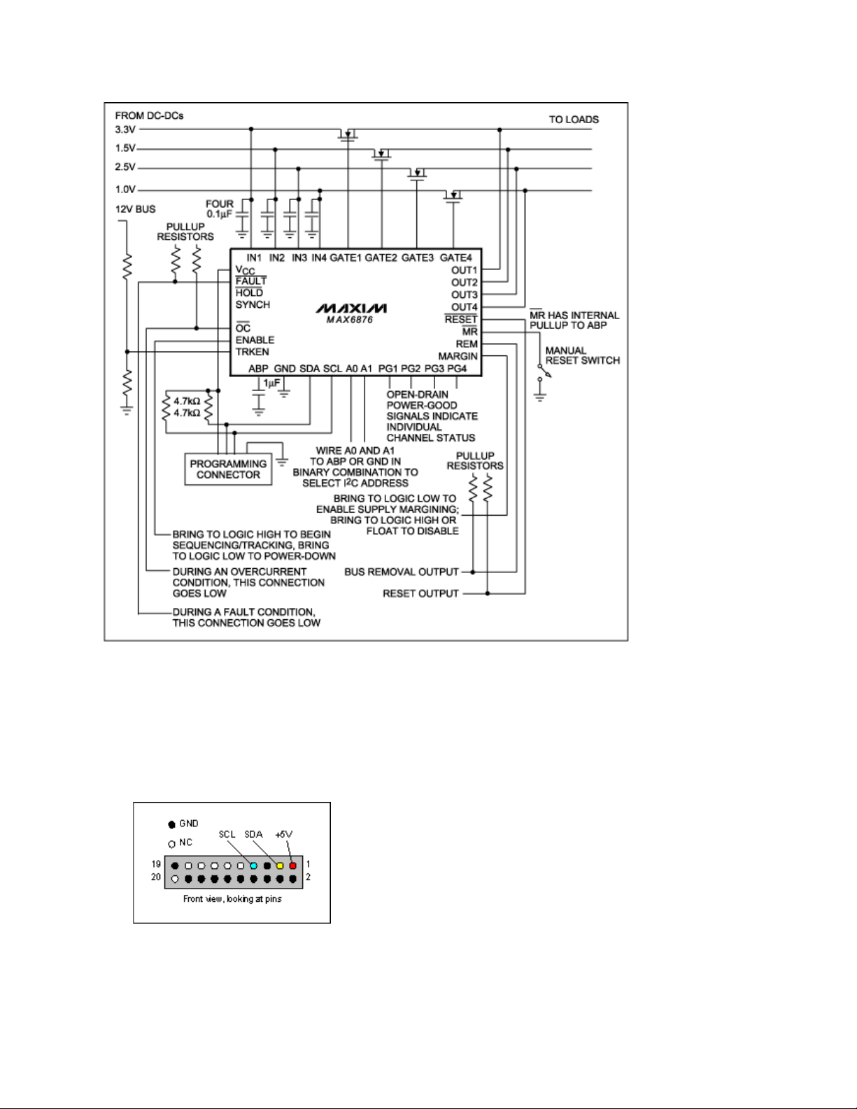
Figure 1. A diagram of the MAX6876's basic connections.
Page 2 of 6
To create a basic design with the MAX6876, use the following steps:
1. Download and install the MAX6876 Evaluation Kit software.
2. Connect a CMOD232 board (included in the Evaluation Kit) to the host computer using an RS232 cable
(not a "null modem" type cable). Note that the MAX6876 Evaluation Kit software does not yet support the
newer CMAXQUSB interface board.
3. Connect the CMOD232 board to either the MAX6876 Evaluation Kit or the application circuit board. The
pinout of the CMOD232 connector P3 is as follows:
Figure 2. The pinout of the CMOD232 connector P3.
4. To connect to the CMOD232 and the MAX6876, launch the Evaluation Kit software, select System-
Page 3
>Connect from the menu, and choose OK.
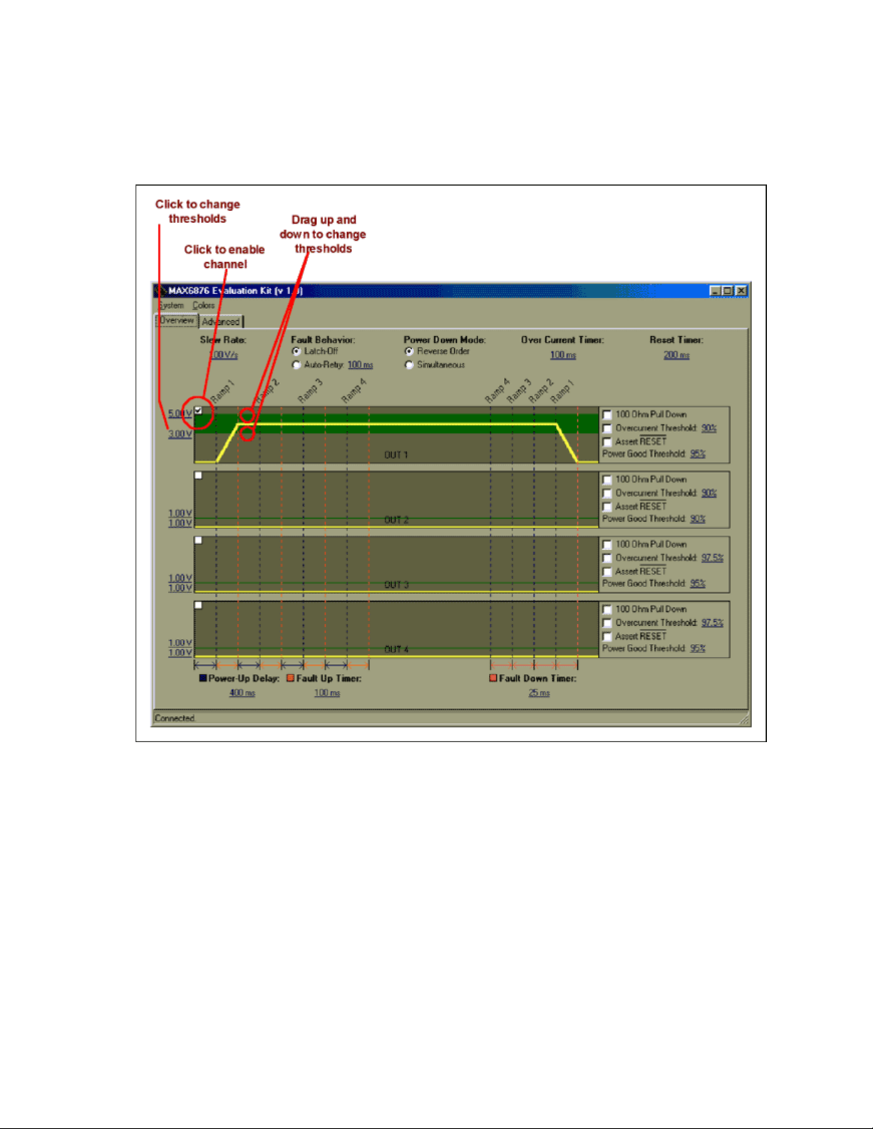
5. To enable a channel, click the checkbox in the upper left corner of each channel window; next, set the
Page 3 of 6
undervoltage and overvoltage thresholds by either clicking the voltage to the right of the window or
dragging the waveform.
Figure 3. This screen capture illustrates how to enable a channel and set the thresholds of the MAX6876
with the Evaluation Kit software.
6. Select the sequence for each channel by dragging the base of each ramp. Reverse sequencing can be
turned-on using the Power Down Mode option buttons.
Page 4
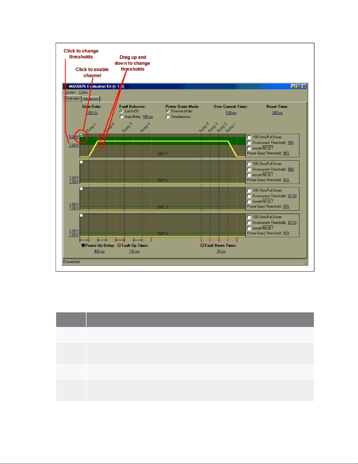
Figure 4. This screen capture illustrates how to configure the MAX6876 for mixed -mode
Page 4 of 6
tracking/sequencing.
7. Consult Table 1 and select the appropriate options for each channel.
Table 1. Channel-Control Options.
Option
Name
100 Ohm
Pull Down
Overcurrent
Threshold
Assert
RESET
Power
Good
Threshold
Function
Activates a 100Ω pulldown resistor on the channel's OUT connection during shutdown only.
Activates overcurrent monitoring on the channel. This compares the IN_ voltage to the OUT_
voltage. When OUT_ falls below a percentage of IN_, Overcurrent Threshold asserts the OC
output (bringing it low).
Activates this channel's control over the RESET line. If this channel falls below its powergood threshold, RESET asserts low.
When the channel's OUT voltage is within this percentage of the IN voltage, the
corresponding PG pin asserts (goes high impedance).
Page 5
8. To set the slew rate, click the Slew Rate selection on the upper left portion of the screen.
9. Set the power- up delay by clicking Power - Up Delay in the lower left portion of the screen. The power- up
assert the OC output. Set the Over Current timer to a value that will not cause glitches to prematurely
Page 5 of 6
delay is the amount of time it takes for a channel to track up after another channel goes into power- good
mode.
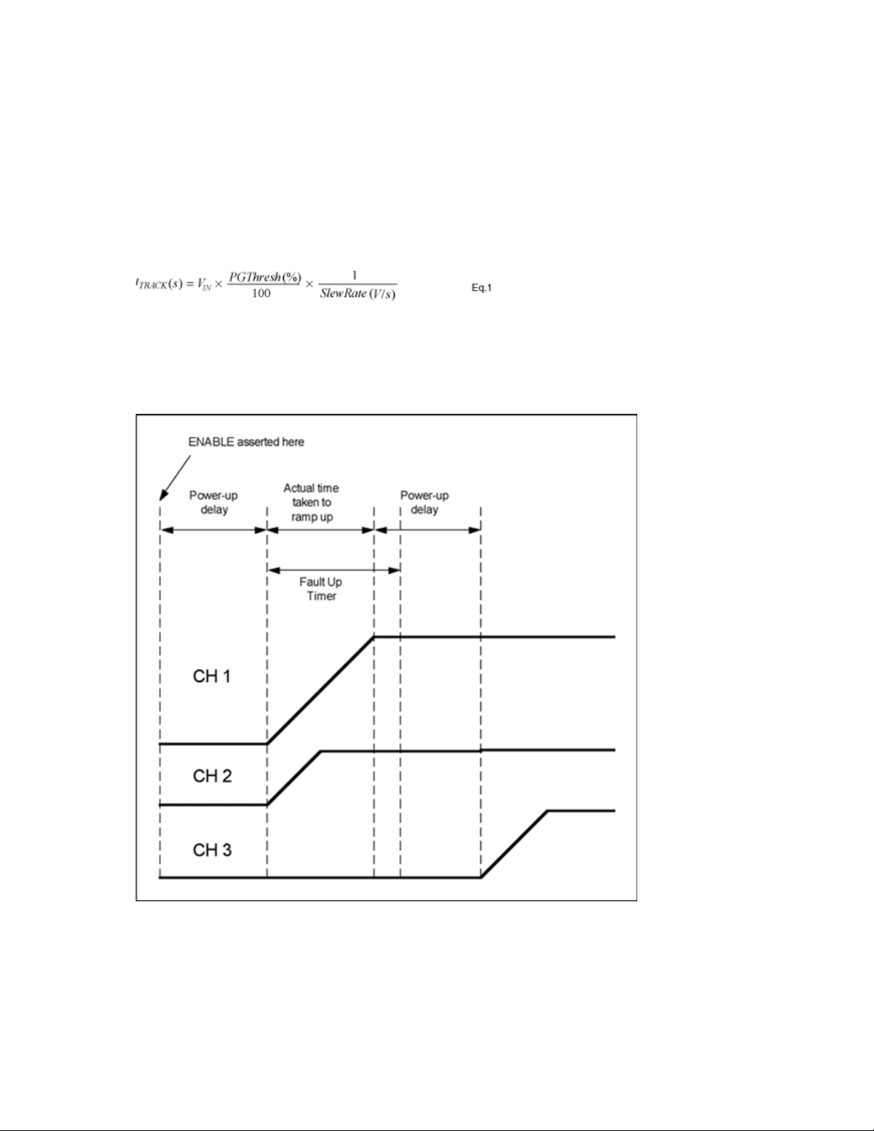
10. Set the Fault Up Timer and the Fault Down Timer. These are the maximum allowable times for a channel
output to ramp from zero volts to the channel input voltage, or from the channel input voltage to zero volts.
Be very careful when setting the fault timers: it is possible to generate an unnecessary fault by using slow
slew rates and fast fault timers. The time for a single voltage to track up from zero volts can be calculated
with the following formula:
For example, with a VIN of 3.3V, a Power Good Threshold of 95%, and a Slew Rate of 100V/s, the time
required to ramp-up/-down is 31.35ms. Therefore, the Fault Up Timer and Fault Down Timer must be set
to at least 50ms—the 25ms option would cause FAULT to be asserted. If more than one channel is
ramping-up/-down at the same time, the two voltages will track; it is, therefore, possible for the ramp - up/down time period to be longer than the theoretical calculation.
Figure 5. Power- Up and Fault Timings for the MAX6876.
11. Set the Fault Behavior option. In Latch - Off mode, the device shuts off after a fault and waits for ENABLE
to be toggled before trying again. In Auto-Retry mode, the device tries again at the specified interval.
12. The Over Current Timer setting determines how long an overcurrent condition must be present in order to
Page 6

assert the OC output.
13. The Reset Timer setting determines the RESET pulse width. Set the Reset Timer to a value that is
Page 6 of 6
guaranteed to reset the microprocessor connected to the pin.
14. Once all parameters are set, write them to the MAX6876 EEPROM by selecting System→Commit
Configuration to EEPROM.
15. The configuration can be saved to a file by selecting System→Save Configuration. All of the registers are
written to this configuration file.
Multiple MAX6876 devices can be connected together for more than 4 channels, but this multiple-device
configuration only operates in tracking mode, in which all channels ramp- up at once. See the datasheet for
more information and an application circuit for connecting multiple MAX6876 devices.
Related Parts
MAX6876 EEPROM-Programmable, Quad, Power- Supply
More Information
For Technical Support: http://www.maximintegrated.com/support
For Samples: http://www.maximintegrated.com/samples
Other Questions
Application Note
USER GUIDE 3917, AN3917, AN 3917, APP3917, Appnote3917, Appnote 3917
Copyright © by Maxim Integrated Products
Additional Legal Notices:
Tracker/Sequencer Circuit
and Comments:
http://www.maximintegrated.com/contact
3917: http://www.maximintegrated.com/an3917
http://www.maximintegrated.com/legal
Free Samples
 Loading...