

Page 1

EE-Sim User Manual
Online Edition
March 2014
Page 2

EE-Sim User Guide
Table of Contents
1 Getting Started .............................................................................. 4
1.1 Introduction ..............................................................................4
1.2 Registering as a New User ..................................................................4
1.3 Starting EE-Sim ...........................................................................5
1.3.1 Using EE-Sim as a New User ............................................................5
1.3.2 Using EE-Sim as the Recipient of a Shared Design ...........................................6
1.3.3 Opening an Existing Design ............................................................7
1.3.4 Saving Changes to an Open Design ......................................................7
1.3.5 Logging Out of EE-Sim .................................................................8
1.4 Web Browser Configuration for Easy Automatic Logins . . . . . . . . . . . . . . . . . . . . . . . . . . . . . . . . . . . . . . . . . . . . 8
1.4.1 Configuring Microsoft Internet Explorer for EE-Sim............................................8
1.4.2 Configuring Mozilla Firefox for EE-Sim .....................................................9
1.4.3 Configuring Google Chrome for EE-Sim ....................................................9
2 Designs, Contacts, and Sharing ................................................................ 10
2.1 Managing Your Designs ...................................................................10
2.1.1 Creating a New Contact................................................................11
2.1.2 Managing Your Contacts ...............................................................12
2.1.3 Sharing a Single Design ...............................................................13
2.1.4 Sharing Multiple Designs...............................................................14
3 DC/DC Conversion Designs ................................................................... 15
3.1 Creating a New Design ....................................................................15
3.2 Specifying Input, Output, and Other Design Requirements........................................16
3.3 Generating a Schematic and Saving Your Design ...............................................17
3.4 Next Steps..............................................................................17
3.5 Modifying Schematics.....................................................................18
3.5.1 Modifying Product Components . . . . . . . . . . . . . . . . . . . . . . . . . . . . . . . . . . . . . . . . . . . . . . . . . . . . . . . . . 18
3.6 Simulation and Analysis ...................................................................20
3.6.1 Running a Simulation and Generating Waveforms ...........................................20
3.7 Generating a Summary Page and BOM (DC-DC) ...............................................22
3.7.1 Generating and Printing a Summary Page .................................................22
3.7.2 Generating and Saving a BOM ..........................................................22
page 2
Page 3

EE-Sim User Guide
4 System Power Designs ....................................................................... 23
4.1 Creating New System Power Processor Designs ...............................................23
4.1.1 Creating a New FPGA Processor Design and Schematic......................................23
4.1.2 Creating a New Processor/SoC/Custom Load Design and Schematic ...........................24
4.2 Next Steps..............................................................................25
4.3 Modifying System Power Schematics.........................................................26
4.3.1 Adding and Connecting Product Components..............................................26
4.3.2 Selecting a Component ...............................................................28
4.4 Sequencing .............................................................................30
4.4.1 Adding a Sequencer ..................................................................30
4.4.2 Editing the Group/Rail Assignments and Viewing the Timing Diagrams ..........................31
4.5 Generating a Summary Page and BOM (System Power) .........................................31
4.5.1 Exploring the System Power Tool Summary Page ...........................................31
4.5.2 Generating and Printing a Summary Page .................................................33
4.5.3 Generating and Saving a BOM..........................................................33
5 Filter Designs............................................................................... 34
6 PLL/VCO Designs ........................................................................... 35
7 The EE-Sim Application for Windows ............................................................36
7.1 Downloading the Desktop Edition of EE-Sim....................................................36
7.2 Installing the Desktop Edition of EE-Sim .......................................................36
7.3 How to Start Using the EE-Sim Application for Windows ..........................................39
7.4 Downloading a Schematic..................................................................42
page 3
Page 4

EE-Sim User Guide
1 Getting Started
1.1 Introduction
As a registered member of the Maxim Integrated online community, you can
use the Maxim EE-Sim® tool to design, simulate, analyze, and purchase a
variety of analog and power solutions. You can also view customized DC/DC
and sequencer recommendations for multi-rail or multi-load systems including
processor, SoC, uC, and FPGA designs.
EE-Sim automatically creates a circuit schematic based on your requirements,
saving you precious design time and resources. Set up and complete your
simulations in just minutes. You can also take advantage of the following
additional features of EE-Sim:
• Share your designs with a colleague
• Order a BOM from your distributor of choice
• Print a complete report
• Download your own free version of EE-Sim
While you are online using EE-Sim, don’t forget to explore the other features
and benets of online membership with Maxim Integrated.
1.2 Registering as a New User
This section guides new users through the registration process, setting up an
account prole, and creating login credentials.
1. Open your web browser and navigate to www.maximintegrated.com.
2. At the top of the page, click Register. If your user name appears at the
top of the page and you do not see a Register button, you are already
registered and logged in. Skip the remaining steps in this procedure.
3. If you arrived at the EE-Sim page through a shared design or another
web link, and you are a new user, click Register if you are a new user.
4. Enter your contact information, including your email address, and specify
a password.
5. Click Submit.
6. Open the desktop application, website, or mobile device you use to
access email for the account you used to register.
7. Look for a new message with the subject line Maxim Member Center
Notier from the Maxim Member System. Open the message and click
the activation link.
8. Congratulations! You are now a welcome new member at Maxim
Integrated!
page 4
Page 5

EE-Sim User Guide
1.3 Starting EE-Sim
As a registered user, you can now start using EE-Sim. You can start EE-Sim
directly or you may start the tool as the recipient of a shared design from
another user.
1.3.1 Using EE-Sim as a New User
Use the following procedure if you are new to Maxim Integrated and are using
EE-Sim for the rst time.
1. Start EE-Sim by any of the following methods:
a. Navigate to www.maximintegrated.com, click the Design menu,
b. Search for a part and open the online product folder. For parts that
c. Create a Bookmark or Favorites link to
2. Because you already registered with Maxim Integrated, you can now
click Login if you are a returning user and begin using EE-Sim. If your
user name appears at the top of the page and you do not see a Login
option, you are already logged in and can skip step 3.
3. On the Member Log In page:
a. In the User Name eld, enter your email address.
and then click EE-Sim.
are available in EE-Sim, an EE-Sim link will appear at the top of
the part’s Description. Click the Create a design and simulate
using EE-Sim link.
http://www.maximintegrated.com/ee_sim/.
b. In the Password eld, enter the password for your Maxim account.
c. Click the Log In button.
4. On the EE-Sim main page:
a. Click the My Designs tab to view your saved designs, as well as
any designs that were shared with you.
b. Click the New tab to create a new design.
page 5
Page 6

EE-Sim User Guide
1.3.2 Using EE-Sim as the Recipient of a Shared Design
The following procedure applies to users who receive an email invitation to
open a shared design.
Note:IfthisisthersttimeyouarevisitingtheMaximIntegratedonlinemember
community,navigatetohttps://memcenter.maximintegrated.comand
clickRegister for Membership.See1.2HowtoRegisterasaNewUser.
1. Open the desktop application, website, or mobile device you use to
access email.
2. Open the shared design’s email invitation:
a. Examine the subject line and notes at the bottom of the invitation.
The owner of the design may have included special instructions for
you.
b. The name of the design and your permissions appear. For
example, you may have Read/Write permissions for one design
and Read Only permissions for another design.
c. Click the accept this invitation link. If you already registered,
you can click the link to the shared design in the sender’s email
invitation.
3. If you are logged in, skip ahead to the next step. If you are not logged in
automatically, complete the Member Login page:
a. In the Email Address eld, enter the email address you used to
register with Maxim.
b. In the Password eld, enter the password for your Maxim account.
c. Click the Log In button.
4. On the EE-Sim main page:
a. Click the My Designs tab to view the shared design, as well as
any additional designs that you save or receive through sharing.
b. Click a design to open it.
page 6
Page 7

EE-Sim User Guide
1.3.3 Opening an Existing Design
Use this procedure to open and resume work on a saved design. For example,
you may have closed your browser or are using a different computer and want
to reopen one of your designs. You can also use this procedure to open a
shared design and save a copy that you can edit as the owner of the design.
1. Open your web browser and navigate to
http://www.maximintegrated.com/ee_sim/.
2. If you are logged in, click Start the EE-Sim tool and skip the next step.
3. If you are not logged in automatically, click Login if you are a returning
user and complete the Member Login page:
a. In the Email Address eld, enter the email address that you used
when you registered.
b. In the Password eld, enter the password for your Maxim account.
c. Click the Log In button.
d. On the Login Successful page, click Start the EE-Sim tool.
4. Click the My Designs tab.
5. On the My Designs page, click the Name link or position your mouse
over a design and click the Open button.
6. In the Loading design will overwrite your existing design... message,
click OK. EE-Sim opens the design at the last saved page in the design
process.
1.3.4 Saving Changes to an Open Design
When you open a design, and have read/write access, you can either overwrite
the original design or save your design changes as a new design.
1. Click the My Designs tab.
2. On the My Designs page, click the Name link or position your mouse
over a design and click the Open button.
3. In the Loading design will overwrite your existing design... message,
click OK. EE-Sim opens the design.
4. Make any desired changes to the design.
5. Click the Save button to save your design. In the Save Your Design
window, click the Save button again to update the design with same
lename.
6. To save your design changes as a new design:
a. Click the Save button to save your design.
b. In the Design Name eld, enter a unique new name to differentiate
this design from your other designs, as well as the shared
designs of other users. For example, save the MAXIM 17598
MyDesign-001 design as MAXIM 17598 MyDesign-002.
c. In the Design Description eld, you may enter a short description
of the modied design for yourself and any recipients with whom
you may share the design.
d. Click Save.
page 7
Page 8

EE-Sim User Guide
1.3.5 Logging Out of EE-Sim
EE-Sim was designed with easy login/logout in mind. Follow these steps to end
your session.
1. Click the Save button to save any changes you made to your design.
2. Close your browser.
Note:ThenexttimeyoustartEE-Sim,youareloggedinautomaticallyunlessyouchecked
the Delete browsing history on exitoptioninyourwebbrowser.
(Optional)Tocompletelyexitthetool,clicktheMaximIntegratedlogo.Logoutof
theMaximwebsiteusingthelinkintheupper-rightcorner.
1.4 Web Browser Conguration for Easy Automatic Logins
When you log in to the Maxim Integrated website, you can rely on standard
security protocols to keep you logged in as a convenience. If you return to the
site and are not automatically logged back in, you will have to manually enter
your login credentials again. You may encounter this behavior for any of the
following reasons, all involving options available to you through your choice
of supported web browser (Microsoft Internet Explorer 9, 10, or 11, Google
Chrome, Mozilla Firefox, or Apple Safari):
• You cleared your browser cookies at any time after your last successful
login. Cookie settings might be cleared on a shared workstation by a
network security policy, or cleared from your own PC as a personal
preference, or by your anti-virus program.
• You are browsing in your web browser’s private or incognito mode.
• You are using a different browser, computer, or device from the one you
used to login last time.
To allow Maxim Integrated to log you in automatically, congure your web
browser as described in the following topics.
1.4.1 Conguring Microsoft Internet Explorer for EE-Sim
Use this procedure to enable automatic logins or if you see the This page can’t
be displayed error page in Internet Explorer.
1. Open Internet Explorer 9, 10, or 11 for Microsoft Windows 7 or 8.
2. Click the Tools menu and select Internet Options.
3. In the Browsing History section, uncheck the Delete browsing history
on exit check box. Or, if you want to check it, click Delete and uncheck
the Cookies and website data check box.
4. Click the Privacy tab.
5. Click the Advanced button.
6. Select the Override Automatic Cookie Handling checkbox.
7. Select Accept for First-party Cookies and Third-party Cookies.
8. Select the Always allow session cookies check box.
9. Click the OK button.
10. Click the Advanced tab.
11. In the scrolling list of Settings, scroll down or press the Page Down key
to go to the bottom of the list to the series of Security check boxes.
12. Check Use SSL 3.0 and Use TLS 1.0.
13. Click OK to close the Internet Options window.
page 8
Page 9

EE-Sim User Guide
1.4.2 Conguring Mozilla Firefox for EE-Sim
1. From the menu bar, click on Tools.
2. From the Tools menu, select Options.
3. In the Options window, select the Privacy icon.
4. If the Firefox will drop-down option is Never remember history, cookies are deleted from the browser when you close it. Change the option to
Remember history so that the cookie is retained between sessions.
5. If the Firefox will drop-down option is Use customer settings for
history, ensure that both the Accept cookies from sites and Accept
third-party cookies boxes are checked (ON) and the Keep until
drop-down option value is set to they expire.
6. In the Options window, select the Content icon.
7. Uncheck (OFF) the check box for Block Popup Windows. Or, if you
choose to have it checked (ON), add the maximintegrated.com domain to
the list of Allowed Sites.
8. Check (ON) the check box for Load Images automatically.
9. Check (ON) the check box for Enable JavaScript.
10. In the Options window, select the Advanced tab.
11. Select the Security section.
12. Check (ON) the check box for Use SSL 2.0.
13. Check (ON) the check box for Use SSL 3.0.
14. Click on OK button to close the Options window.
1.4.3 Conguring Google Chrome for EE-Sim
1. Click on the Customize and Control Google Chrome menu and
choose
Settings.
2. Click on the Show Advanced Settings link at the bottom of the page.
3. In the Privacy section, click Content Settings.
4. Select Allow local data to be set (recommended).
5. Click Done.
6. If you ever click Clear browsing data in the Privacy section to clean up
your PC or troubleshoot a separate issue that is not related to EE-Sim,
remember to uncheck Delete cookies and other site and plug-in data.
If checked you will have to login to EE-Sim again.
7. Click Cancel.
8. Scroll down to Network and click Change proxy settings.
9. In the Internet Properties window, click the Advanced tab.
10. In the Settings scrolling list, scroll down or press the Page Down key to
go to the bottom of the list to the series of Security check boxes.
11. Check Use SSL 3.0 and Use TLS 1.0.
12. Click OK to close the Internet Properties window.
13. Close the Settings tab in Chrome.
page 9
Page 10
EE-Sim User Guide
2 Designs, Contacts, and Sharing
2.1 Managing Your Designs
There is no particular procedure for managing your designs. As you create and
share them, your design list will grow. The following graphic provides a visual
summary.
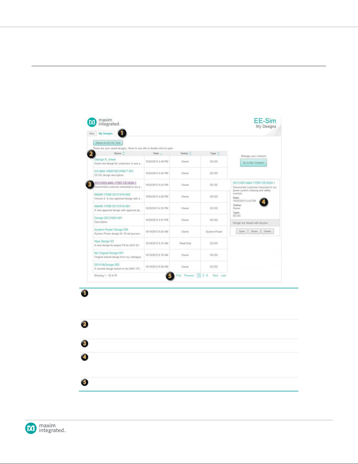
MyDesigns:Clickthe My Designstab to view,manage,sort,open, share, and delete yourdesigns. If you navigateto
the MyDesignspagefromanopendesign, abutton appears to take you back to the last pageyou were viewingso
that youcancontinueworking on the opendesign. Thebuttonnamecorresponds to thelast EE-Sim design module
youopened.Possible buttonnames include Return toDC DC Tool,Return to System Power Tool, Return toPLL Tool,
orReturn toFilter Tool.
Sort Order:Clickthe column headersto toggle theascending/descendingsort order foreachcolumn.Inthis example,
the entire tableofdesigns is sorted by datein descendingorder(indicatedbythearrow pointing down in theDate
columnheader).
Open aDesign:Click the designname hyperlinktoopen a design.Thevaluein the Statusfielddenotesyour
permissions(ReadOnly,Read/Write, orOwner).
Sharing:Position your mouse overa row in the designs table to viewits full descripti on, sharedcontacts, and
permissions. Availablebuttonsinclude Open,Share, and Delete. In the topexample, theowner of aDC-DCdesignhas
notshared itwith anyone. Inthebottom example, a contactperson has been grantedRead-Only permission to a
System-Power design.
Navigation: Use theconvenient linksatthe bottomof the list to navigate throughmultiplepages with up to ten (10)
designs appearingon eachpage.
page 10
Page 11

EE-Sim User Guide
2.1.1 Creating a New Contact
Before sharing a design with a colleague, you must add them as a new contact.
1. Click the My Designs tab.
2. Click the Go to My Contacts button.
3. In the Add New Contact eld:
a. Enter the email address for your new contact.
b. Click Add Contact.
4. In the Invite Preview section:
a. In the Subject eld, enter a subject line for the email message to
your new contact.
b. In the Message section, enter a custom greeting to follow the
Hello line and your name as the person who wants to add you as
a contact on Maxim EE-Sim. You can also add custom notes at the
bottom of the invitation.
5. Click Add Designs to Share to assign permissions to one or more of
your designs for your new contact to view or edit them. In the Share
multiple designs... window:
a. Select the Read/Write option to enable the new contact to edit the
shared design.
b. Select the Read Only option to enable the new contact to view
your design. Your original design is preserved. The recipient can
save their own new edition of the design.
c. Select the No Access option to restrict permissions. Designs with
this option are not shared.
d. Click Apply.
6. Review the invitation and click Send Invite.
Note:NewcontactsmayappearinthePending Contactssectionuntiltheyaccept
yourinvitation.
7. (Optional) To revise the invitation, click Resend Invite.
8. To return to your designs, click the Go to My Designs button.
page 11
Page 12

EE-Sim User Guide
2.1.2 Managing Your Contacts
EE-Sim helps you organize your contacts, send email invitations, and set
sharing permissions for collaboration in viewing, approving, or developing new
designs.
1. Click the My Designs tab.
2. Click the Go to My Contacts button.
3. In the My Contacts section:
a. Click a column header to sort your contacts by either their
email address or the number of designs you have shared with
Read/Write or Read Only permissions.
b. Position your mouse over a contact to view the names of any
shared designs.
c. Click First or Last to jump to the rst or last page in the list.
d. Click Previous or Next to go back or advance one page at a time.
e. Click a page number to view that page of ten contacts. The current
page is shown with a border around its number.
4. Click Manage to set the design’s sharing permissions that you want to
grant to this contact, if any. In the resulting Share multiple designs...
window:
a. Click a column header to sort the list by design name or permitted
level of access.
b. Click Apply to save any new permission preferences.
c. Click Preview and Send Invitation to send your contact a
personalized message about the sharing privileges changes you
just made.
d. (Optional) Click Share with a new contact to exit this window and
share designs with a new contact. To learn more, see 2.1.1 How to
Create a New Contact.
5. New contacts are added to the Pending Contacts section if their email
address is not recognized as an existing EE-Sim user. In the Pending
Contacts section, you can perform any of the following actions:
a. Click a column header to sort your contacts by their email account,
invitation date, shared designs, or sharing action.
b. Click First or Last to jump to the rst or last page in the list.
c. Click Previous or Next to go back or advance one page at a time.
d. Click a page number to view a specic page of ten contacts. The
current page is shown with a border around its number.
e. Click Resend Invite to adjust any design sharing permissions, edit
your personalized invitation, and/or email it to the pending contact
again.
6. In the Add New Contact section, enter an email address and click Add
Contact to begin the sharing process or notify another contact.
7. Click Go to My Designs when nished to return to your list of designs.
page 12
Page 13

EE-Sim User Guide
2.1.3 Sharing a Single Design
Use this procedure to share a specic design with a contact. You have two
options: start at step 1 or 2.
1. (Option 1) On the My Designs page, position your mouse over the
design you want to share. In the dynamic status area that appears on the
right side, click Share.
a. In the Manage Permissions window for the selected design choose
Read/Write, Read Only, or No Access for each contact in the list.
(This option enables you to share the design with multiple contacts.)
b. (Optional) Click Apply to save your settings.
c. Click Preview and Send Invitation.
2. (Option 2) Open a design and click the Share button in the upper-right
corner of the page, if available. The Share button may not appear on all
pages.
a. In the Share Your Design window, select a contact (or click
Add Contact) to enter a new contact in the Share With eld.
b. In the Set Permissions Level eld, choose Read Only or
Read/Write.
Note:Forbothoptions,continuewiththefollowingcommonsteps.
3. In the Subject eld, enter a subject line for the email message to your
new or existing contact.
4. In the Message section:
a. EE-Sim shows Hello. Enter the name of the person receiving
your design.
b. EE-Sim may enter your name as the person who is sharing a
design. You can edit the name.
c. You can also add notes in the Additional comments eld at the
bottom of the invitation.
5. Review the invitation and click Send Invite.
page 13
Page 14

EE-Sim User Guide
2.1.4 Sharing Multiple Designs
Use this procedure to share multiple designs at the same time with a single
contact.
1. On the My Designs page, click Go to my Contacts.
2. On the My Contacts page, locate a specic contact in the list and click
the Manage button.
3. In the Share Multiple Designs window:
a. Select Read/Write or Read Only for each design in the list. Select
No Access to disable sharing of that design.
b. (Optional) Click Apply to save your settings.
c. Click Preview and Send Invitation.
4. In the Subject eld, enter a subject line for the email message to your
contact.
5. In the Message section:
a. EE-Sim shows Hello. Enter the name of the person receiving
your design.
b. EE-Sim may enter your name as the person who is sharing a
design. You can edit the name.
c. You can also add notes in the Additional comments eld at the
bottom of the invitation.
6. Review the invitation and click Send Invite.
page 14
Page 15

EE-Sim User Guide
3 DC/DC Conversion Designs
As a registered member of the Maxim Integrated online community, you can
use the Maxim EE-Sim® DC-DC Conversion tool to design, simulate, analyze,
and purchase a variety of power solutions, including step-up, step-down, and
isolated congurations.
EE-Sim automatically creates a circuit schematic based on your requirements,
saving you precious design time and resources. Set up and complete your
simulations in just minutes. You can also take advantage of the following
additional features of EE-Sim:
• Share your designs with a colleague.
• Order a Bill of Materials (BOM) from your preferred distributor.
• Print a complete report.
• Download your own free version of EE-Sim.
While you are online using EE-Sim, don’t forget to explore the other features
and benets of online membership with Maxim Integrated.
3.1 Creating a New Design
You can use EE-Sim to create an unlimited number of new designs. After
entering your detailed input requirements, you can generate an interactive
schematic with components you can modify.
1. Open your web browser and navigate to
http://www.maximintegrated.com/ee_sim/.
2. Click Start the EE-Sim tool or Login if you are a returning user.
3. If you are logged in, skip ahead to the next step. If you are not logged in
automatically, complete the Member Login page:
a. In the Email Address eld, enter the email address that you used
when you registered.
b. In the Password eld, enter the password for your Maxim account.
c. Click the Log Me In button.
d. On the Login Successful page, click Start the EE-Sim tool.
4. On the New tab, select DC/DC Conversion.
5. Expand a category to view a list of Maxim products.
6. (Optional) Click to view additional product information, including
ordering details and the product data sheet.
7. Click the part number to create a new design based on that part.
8. The Design Requirements page appears. EE-Sim displays the part
number you selected in the upper left corner.
For example:
Part Number: MAX17598
Design Name: Not Saved
9. Continue to the next section for instructions on developing your design.
page 15
Page 16

EE-Sim User Guide
3.2 Specifying Input, Output, and Other Design Requirements
EE-Sim lls in default design requirements for the part you selected. Use this
procedure to edit those values before generating a schematic.
1. On the Design Requirements page:
a. In the Input Requirements section, enter your input values in
each eld.
b. In the Output Requirements section, enter your output values in
each eld.
c. In the Design Criteria section, enter your settings in each eld.
2. If available, click Show Advanced to view additional requirements. Click
Hide Advanced to hide the additional requirements and simplify the
current page.
Note:Eventhoughyoumaychoosenottoviewthem,hiddenadvancedrequirements
arestillusedinthedesign.
3. Apply any of the following tips to save time and improve accuracy:
a. Press the Tab key to move to the next eld.
b. Verify that the values you enter are in the correct eld and in the
required units.
c. In some browsers, such as Internet Explorer 10, you can click a
small x to clear the value of a eld.
d. In elds that require a limited set of acceptable values, you can
enter a value using any of the following methods:
• Click the drop-down menu icon and choose a value.
• Type the rst digit of the closest matching value.
• Press the Tab key to enter the eld and then press the Up or
Down arrow keys.
4. A message may appear when your value is not acceptable. Read the tip,
click OK, and adjust the value as advised. The tool automatically inserts
a suggested value.
5. (Optional) Click the Restore Defaults button to revert all elds back to
their original values.
6. Continue to the next topic.
page 16
Page 17

EE-Sim User Guide
3.3 Generating a Schematic and Saving Your Design
In the two previous procedures, you selected a part and entered your design
requirements. Follow these steps to generate a schematic and save your new
design.
1. When all your values have been entered, click Create Design.
2. EE-Sim performs a complex set of calculations to design a circuit that
meets your requirements. A visual representation of your design appears
on the Schematic page. Where practical, the tool also identies specic
supporting components.
3. Click the Save button to save your design. In the Save Your Design
window:
a. In the Design Name eld, enter a unique name to differentiate this
design from your other designs as well as the shared designs of
other users.
b. In the Design Description eld, enter a short description of the
design to remind you later of its purpose. The description is also
helpful for any recipients if you decide to share the design.
c. Click Save.
3.4 Next Steps
Congratulations! You’ve generated a schematic and saved your design. You
can now perform one or more of the following tasks.
Task Step Learn More
To modify your design Click the Design Requirements tab
To edit your schematic Click the Schematic tab. 3.5 Modifying Schematics
To run simulations Click the Analysis tab and enter your
To complete the design, view a
summary, and download a BOM
To download one or more
designs
Note: You are not required to visit every tabbed page in EE-Sim.
to change your design requirements
and then click Create Design to
generate a new schematic.
simulation settings.
Click the Complete Your Design
tab and perform any of the available
options.
Click the Download Designs tab and
perform any of the available options.
3.2 How to Specify Input, Output,
and Other Design Requirements
3.6 Simulation and Analysis
3.7 Generating a Summary Page
and BOM
7.4 How to Download a Schematic
page 17
Page 18

EE-Sim User Guide
3.5 Modifying Schematics
3.5.1 Modifying Product Components
You can change component settings, parts, and even switch manufacturers.
You can choose stock or custom settings in a design.
1. Open a design and click the Schematic tab.
2. Click a component to open and edit it. In the example shown below, the
C16 capacitor is opened in the schematic diagram.
3. In the Edit window:
a. Expand Use Vendor Part to view the currently selected
component. To switch components, click Search for a
Different Part. Continue with the remaining steps in this
procedure.
b. (Optional) Expand Use Custom Part to enter your own setting. For
example, you can change the Capacitance from 33 nF to 31 nF.
Click OK and exit this procedure.
4. Apply one or more lters to search for the required manufacturers,
attributes, and products. To learn more, see the example on the next
page.
5. In the search results:
a. Click a product by its Manufacturer Part Number to learn more
about it.
b. Click the Select icon to swap the old part for the new one.
6. Click OK to close the Edit window.
page 18
Page 19

EE-Sim User Guide
Available Filters: This section lists your search opti ons.Defaultsetti ngs are based on the design requirements thatyou entered
foryourdesignbefore generatingthe schemati c. Make adjustments tofi nd only the partsofinterest toyou.
FilterControls: Scroll from left to right to view all available fil teropt i ons. ClickHide Appliedto hide filtercriteria fromthepage
Filters button to beginyoursearch forproducts that matchyoursearch criteria.
original partwith anew one. Your changes arereflected immediately in the schematic.
Selected Part: Thetopofthe window shows the originalpartyou selectedinthe schematic.
inordertoviewmore searchresults. ClickReset to restoredefaultvalues and ClearAll to removeall values. Click theApply
AppliedFilters: Thissection reminds you of the searchcriteria thatwere used to generatethe listofmatchingparts.
SearchResults: Click a partnumber to learn more abouttheproduct and manufacturer. Click Selectto replacethe
page 19
Page 20

EE-Sim User Guide
3.6 Simulation and Analysis
3.6.1 Running a Simulation and Generating Waveforms
You can use EE-Sim to run an analysis to generate waveforms.
1. Open a design and click the Analysis tab.
2. In the Congure Analysis section, select an option for the Analysis
Selection eld:
a. Click AC Analysis and enter a Start Frequency and
Stop Frequency.
b. Click Transient Analysis and enter a Simulation Stop Time.
c. Click Steady-State Analysis and enter a Simulation Stop Time.
d. Click Startup Analysis and enter a Simulation Stop Time.
Note: Theparametersvarybasedonthedesign.Fieldlabelsmayalsoappearas
StartupandStopTime.
3. Click the Run Analysis button.
page 20
Page 21

EE-Sim User Guide
Waveforms: EE-Sim offersyou several diff erent types ofsimulationresults includingBodeplot, IC, Input, Switching, Output,
Primary,Secondary,and Signals.
WaveformViewer:Clickthe Openin WaveformViewer buttonorclickthe waveform graph toopen theWebScope
Plot,Secondary, or Signals.
Toolbar: Toolbar buttons allow you to zoom in and out, pan, and printyourwaveforms. Position your mouse overeach toolbar
icon to view its function.
Configurati on Data: Youcaneditthe confi gurati on data to update thewaveform. For example, adjustthe startti me,stop
oroff (uncheck) colorizedmarkersin theplottedarea.
ChartLegend: Show,hide,and adjustthesequence of theplottedcurrent (A)andvoltage(V)values.Clicka color square to
values in thewaveform.
Run Analysis: Select an analysis type and enteryourConfi gurati onsettings. ClickRun Analysistogeneratea defaultwaveform.
waveformviewer in aseparate window. You canclickthe tabs available in theviewer to generate and manipulate the plotted
results.The tabs correspond tothe available waveformsfor yourdesign andselected typeof analysis. Forexample, click Bode
time,or change(delta) in ti me.Youcan also indicate Min, Max,RMS,Pk2Pk, Slope, or Avg electricalvalues and turnon(check)
select anew color from the pop-up color selection swatch. Youcanalsoturn on (check) or off (uncheck) a color-coded series of
The following image shows another exampleof the waveform viewer. Inthis example, the IC
theOutput view are turned off. The color selection pop-up appears because we clicked the V
squareicon to change it to another color.
1 values in
OUT
green
OUT
page 21
Page 22

EE-Sim User Guide
3.7 Generating a Summary Page and BOM (DC-DC)
3.7.1 Generating and Printing a Summary Page
You can generate a summary page for your design.
1. Open a design and click the Complete Your Design tab.
2. A summary page appears. Click any of the available options:
a. Click Evaluation Board to view a product evaluation kit with
ordering information, samples, design resources, an overview, data
sheet, and related product links. (If no evaluation board exists for
the part you have selected, the button will not appear.) You can
also subscribe to alerts about the selected product.
b. Click Order Samples to search for product samples. Click the
Sample Now button to add the samples that you want to your
sample cart.
c. Click the Buy button to view product availability, quantities, and
pricing. Click Quote Now for a price quote or Buy Now to make a
purchase.
d. Click Quick View, Data Sheet, or App Notes, if shown, to view
additional information about the part.
3. Click Print Page to print the page to a printer, network copier, fax device,
or to a PDF, XPS, or other le.
Note: If the Simulation ResultssectionoftheCompleteYourDesignsummarypage
displaysthefollowingmessage,itmeansyouhavenotyetclickedRun Analysis
ontheAnalysistab:
Results will be shown here after a simulation has been run.
3.7.2 Generating and Saving a BOM
Use this procedure to generate, view, and save a bill of materials (BOM) for the
current design.
1. Open a design and click the Complete Your Design tab.
2. Scroll down to the Bill of Materials section.
3. In the BOM Engine eld, choose a distributor such as Digi-Key, Avnet,
or Mouser. You can also choose Generic. If available, price and inventory
information appears.
4. (Optional) If pricing information is available, choose an order quantity in
the Price Break eld.
5. (Optional) If you select Digi-Key, you can enter your order quantity and
click Checkout to place this BOM in a shopping cart on the Digi-Key
website.
6. Click Download to save the BOM as a Microsoft Excel spreadsheet
le.
page 22
Page 23

EE-Sim User Guide
4 System Power Designs
As a registered member of the Maxim Integrated online community, you can
use the Maxim EE-Sim® System Power tool to view custom DC/DC and
sequencer recommendations for multi-rail or multi-load systems, including
processor, SoC, uC, and FPGA designs.
EE-Sim automatically validates your part selections based on your
requirements, saving you precious design time and resources. You can also
take advantage of the following additional features of EE-Sim:
• Share your designs with a colleague.
• Order a BOM from one or more distributors.
• Design and simulate individual integrated circuits (ICs).
• Choose power sequencer ICs and view timing.
• Print a complete report.
While you are online using EE-Sim, don’t forget to explore the other features
and benets of online membership with Maxim Integrated.
4.1 Creating New System Power Processor Designs
You can use EE-Sim to create a new processor design and explore the
components required to power it. After entering your detailed input requirements,
you can generate an interactive schematic with components you can modify.
4.1.1 Creating a New FPGA Processor Design and Schematic
Use this procedure to create a new processor design with a Device Type setting
of FPGA.
1. Click the New tab and select SYSTEM POWER.
2. Click Open System Power Tool.
3. On the Design Requirements page, in the Device Selection section:
a. Select FPGA in the Device Type eld.
Note:TheeldsandacceptablevaluesontheDesign Requirementspageautomatically
changebasedonthevalueyouchooseintheDev ice Type eld.
b. In the Manufacturer eld, choose Xilinx or Altera.
c. In the Family eld, choose the product family or series available
from the manufacturer that you selected in the previous step.
d. In the Device eld, choose a specic model number. The list of
available devices corresponds to the product series that you
selected in the Family eld.
4. (Optional) You can click Save now to open the Save dialog box. Name
your design, assign a short description, and click Save. Or, you can
continue developing your design and save it later.
5. In the Power Requirements section, the FPGA Power Estimator
Spreadsheet option is automatically selected for you when you choose
FPGA in the Device Type eld in the previous section.
page 23
Page 24

EE-Sim User Guide
Note:IfyouchangetheDev i ce Type,youroriginalvaluesareremoved.
6. Click Browse.
7. In the Choose File to Upload window, navigate to your Altera or Xilinx
power estimator spreadsheet in a folder or on your computer. Select the
le and click Open.
8. Click Upload.
9. Click Preview Device to view the rails and pins for your device.
a. EE-Sim reminds you to enter any missing design requirements in
the table by placing a red border around the empty cells.
b. (Optional) You can combine loads with the same voltage requirement
by assigning the same Group Number to them. Two or more rows with
a shared group number will be treated as a single rail.
10. Examine the preview image and, if necessary, adjust any values.
11. In the DC Input Requirement section, adjust the default voltage in the
Supply Voltage eld.
12. Click Create Design.
13. Click Save to save your changes.
4.1.2 Creating a New Processor/SoC/Custom Load Design and
Schematic
Use this procedure to create a new processor design with a Device Type setting
of Processor/SoC/Custom Load.
1. Click the New tab and select SYSTEM POWER.
2. Click Open System Power Tool.
3. On the Design Requirements page, in the Device Selection section:
a. In the Device Type eld, select Processor/SoC/Custom Load.
Note:TheeldsandacceptablevaluesontheDesign Requirementspageautomatically
changebasedonthevalueyouchooseintheDev ice Type eld.
b. In the Manufacturer eld, enter a manufacturer.
c. In the Family eld, enter a product family for your choice of
manufacturer.
d. In the Device eld, enter a model number or product identier.
4. (Optional) You can click Save now to open the Save dialog box. Name your
design, assign a short description, and click Save. Or, you can continue
developing your design and save it later.
5. In the Power Requirements section, the Processor/Custom Load
option is selected when you choose the Processor/SoC/Custom Load
value in the Device Type eld.
Note: IfyouchangetheDev i ce Type,youroriginalvaluesareremoved.
page 24
Page 25

EE-Sim User Guide
6. Complete one or more rows in the power requirements table:
a. In the Pin Name eld, enter the unique identier for each pin (for
example, VCCO).
b. In the Group eld, enter an integer number. To combine rails with
the same voltage, enter the same group number for those rails.
c. In the Voltage (V) eld, enter the voltage.
d. In the Ireq (A) eld, enter the amperage.
e. In the Supply Tolerance eld, adjust the tolerance threshold if
you require a value greater than or less than the default value of
±2.5%.
f. To delete a row, click Delete.
g. To add settings for a new pin, click + Add Row.
7. Click Preview Device to view the rails and pins for your device.
a. Any missing values in the table appear with a red border to alert
you to nish entering your design requirements.
b. Correct any conicting voltage values if you assigned a shared group
8. Examine the preview image and, if necessary, adjust any values.
9. In the DC Input Requirement section, adjust the default voltage in the
Supply Voltage eld.
10. Click Create Design.
11. Click Save to save your changes.
4.2 Next Steps
Congratulations! You generated a schematic and saved your design. As a summary,
you can now perform one or more of the following tasks:
Task Step Learn More
To edit your design Click the Design Requirements tab. 4.1 Creating New System Power
To edit your schematic Click the View Schematic tab. 4.3 Modifying System Power
To configure sequencing and
group/rail assignments:
To complete the design, view a
summary, and download a BOM
To download designs Click the Download Designs tab. 7.4 How to Download a Schematic
Note: You are not required to visit every tabbed page in EE-Sim.
number to rows with different voltages. Enter the same voltage for
each row in the group.
Processor Designs
Schematics
Click the Sequencing tab. 4.4 Sequencing
Click the Summary tab. 4.5 Generating a Summary Page
and BOM (System Power)
page 25
Page 26

EE-Sim User Guide
4.3 Modifying System Power Schematics
4.3.1 Adding and Connecting Product Components
You can add, connect, and change components directly in the schematic.
1. Open a system power design and click the View Schematic tab.
2. To add a component, click Add Component and choose a component
from the menu. You can select converters, an input power supply, an
additional load, or another processor.
3. Move the component to a specic location and click in the grid to position
it there.
4. To connect components, drag circuit connection lines by their points and
release your mouse button at the end point or to make a 90° turn in the
line.
Note:Tocorrectamistake,clicktheUndoiconinthetoolbar.Toremoveunwanted
objects,usetheMarquee Selecttooltodrawaboxaroundthemusingyour
mouseandclicktheDeleteicontodeleteallobjectsinthemarqueebox.
5. Refer to the examples described in the following graphic to complete any
additional tasks. For example, you can print, zoom, add wire, and check
a design for errors.
6. Click Save.
7. (Optional) When you make a conscious choice to click Check Design or
a passive choice to navigate away from the View Schematic page,
EE-Sim validates the following design rules:
• The voltages on a given connection match.
• The required current is less than the supplied current.
• The power out is equal to 80% of input power.
• Loads do not have multiple sources.
page 26
Page 27
EE-Sim User Guide
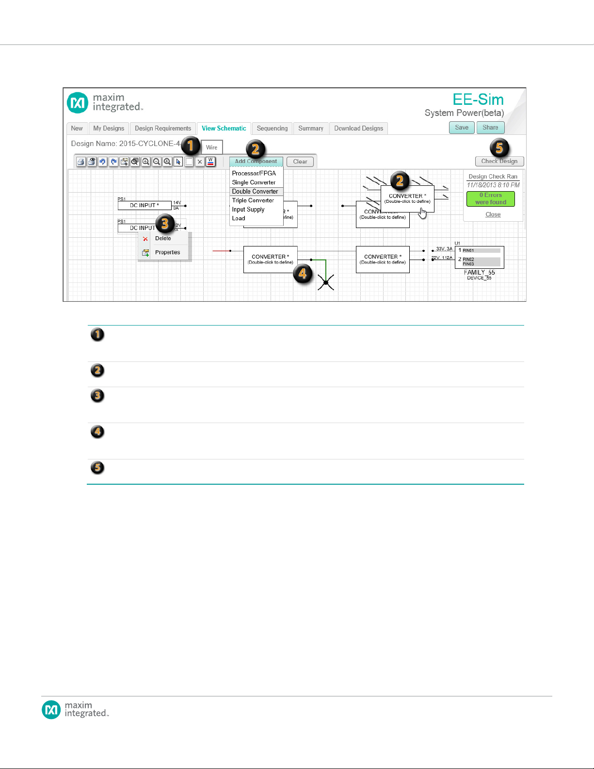
Toolbar: The topof thewindow shows atoolbaryoucanuse to access tool buttons forfamiliar commands.Youwill recognize
anicon to view its functional name in a tooltip.
Add Component: Whenyou click thisbutton, a menu appears.Choose a component.Slowly moveyourmousedownto
position thenew component in the grid.
Right-ClickMenu:Insteadof clickinga componentfirstandthenclicking theDelete toolbar butt on, you canright-clickthe
right-click and choose Properties.
Connection Wires:When positioningyour mouse over a connectionpoint, it changes to theX-shaped wirecursor. Youcan
asstraightlinesegments or 90°connected line segments with no points.
CheckDesign:ClickCheckDesign to determineifthe converters areproperly sized for theloads they are supporting.When
you navigate awayfrom the View Schematic page, EE-Simautomaticallychecks yourdesignand reports anyvalidation errors.
iconsfor the print,undo, redo, zoom, select, delete, and wire commands.To refresh yourmemory, positionyour mouse over
component andchoose Delete from a shortcut menu. Instead of double-clicking a component to view itsproperties, youcan
connecta newgreenlinetoanotherline or point.Red lines representincomplete connections. Completeconnecti ons appear
page 27
Page 28

EE-Sim User Guide
4.3.2 Selecting a Component
You can select and change components directly in the schematic.
1. Open a system power design and click the View Schematic tab.
2. Double-click a component. The resulting window varies for each type of
component.
a. Input Supply: In the Dene Source Supply window, verify or
change the Supply Voltage eld and then click Ok.
b. Processor/FPGA: In the Choose/Congure Processor/FPGA
window, verify, change, or dene the power requirements of each
pin. Click + Add Row to add a new row to the table. To learn more
about creating a new processor in this design, refer to 4.1.1 How
to Create a New FPGA Processor Design and Schematic. When
nished, click Ok.
c. Load: In the Congure Load window, complete the Name,
Required Voltage (Volts), Voltage Tolerance (%), and Required
Current (Amps) elds. Click OK.
d. Converter: In the Find a Solution window, verify or change the
Converter Requirements, apply one or more lters, and then
choose a converter. Click Select Part to use the highlighted part
in your schematic. If the part is available in the EE-Sim DC/DC
Conversion tool, click the Design It button to add the converter
to your schematic and then automatically design and simulate it.
Refer to the following example.
Note:Whenyoudouble-clickaconverterwiththeDesign Itfeature,theDesign
Decisionwindowappears.YoucanclickDesignIttodesignthecomponentoryou
canclickReselecttochooseadifferentpart.IfyouclickDesign It,theEE-Sim
DC/DCConversiontoolappearsinawindow.SeethechapteronDC/DCConversion
Designsforinstructions.
3. Complete any additional tasks. For example, you can print, zoom, add
wire, and check a design for errors.
4. Click Save.
page 28
Page 29

EE-Sim User Guide
Converter Requirements: Verifythe detected voltage and currentvalues arecorrect. Youcanalso modify detected values,or
manually add or deleterails.ClickResettoeraseall custom values on the entire pageand startover.
Apply Filters: ClickShow Filters and checkthe filter criteria youwantto applytonarrow downthe searchresults.CheckDesign
criteriaand simplify theappearanceofthepage.
Display Options andFinal Selecti on Filters: Choose avalueinthe Display resultsfieldtodetermine yourpreferences for
ofthe table. If toofew solutionsappear, tryrelaxing your fil tercriteria.Youcan alsofilter on apart ID.
Select aPart:You may need to scrollor navigatetoview all the matchingsolutions for your fi lter criteria.Positi on your mouse
foryourchosenpart and thenclick theSelect Partbuttonto use itinyour schematic.
ToolAvailable to find soluti ons that feature the EE-Sim DC/DCConverter tool. ClickHide Filtersto stopshowing thefilter
paging and scrolling. Forexample, choose All to view all results in onelong scrollinglist instead of pageby pagewith 10results
per page. If too many solutionsappear, apply specificinputvoltage,output current, and switching frequencyfilters at the top
over theShow link inthe Features column toview asummaryof the keyfeatures forthis device. Thelistincludes features that
matchyourfiltercriteriaaswell asanyotherfeaturestohelp youmake an informed decision.Click on thecircularradiocontrol
page 29
Page 30

EE-Sim User Guide
4.4 Sequencing
4.4.1 Adding a Sequencer
Typically, your design should include at least one sequencer to manage the
ow of power to the rails in the prescribed order.
1. Open a system power design and click the Sequencing tab.
2. Click the Add Sequencer button.
3. In the Find a Solution window:
a. Click Show Filters (it may already be displayed).
b. In the Input Channels section, enter values for the minimum (Min)
and maximum (Max) number of input channels.
c. In the Voltage Input section, enter a value for the Max voltage.
d. In the Interface, Option, and Features sections, check the lter
criteria that you want to apply to narrow the search results for your
sequencer.
e. In the Choose Sequencer section, scroll or navigate to the pages
that show matching parts. You can also click a column heading to
sort or enter a search phrase to nd specic matching sequencers.
4. Select a sequencer in the list and then click Select Part.
5. On the Sequencing page in the Sequencer Selection section:
a. Verify your sequencer appears and the number of input channels
is acceptable.
b. To change parts, click Edit.
c. To delete this sequencer, click Delete.
d. To add another sequencer, click Add Sequencer and repeat the
steps in this procedure.
e. To indicate that you want EE-Sim to produce a timing diagram to
help you verify the timings, check the box for Check for Timing
View.
6. Click Save.
page 30
Page 31
EE-Sim User Guide
4.4.2 Editing the Group/Rail Assignments and Viewing the Timing
Diagrams
Perform these steps to edit the group/rail assignments and generate timing
diagrams.
1. Open a system power design and click the Sequencing tab.
2. Verify that you have added at least one sequencer.
3. Expand the Group/Rail Assignment section. The color-coded FPGA
Groups and Rail(s) data appear only when you have added at least one
sequencer.
4. For each FPGA Group and rail or pin:
a. Choose a sequencer reference designation from the Sequencer
b. Enter a Delay On value in milliseconds. This is the delay from t = 0
c. Enter a Delay Off value in milliseconds. This is the delay from t = 0
5. Click Apply Changes.
6. Expand the Timing Diagram section and examine the Delay On and
Delay Off graphs.
7. (Optional) Position your mouse over a data point in the graph to view its
FPGA group, voltage out, and delay in milliseconds.
8. Click Save.
eld.
seconds before power is applied to the rail.
seconds before power is terminated to the rail.
4.5 Generating a Summary Page and BOM (System Power)
4.5.1 Exploring the System Power Tool Summary Page
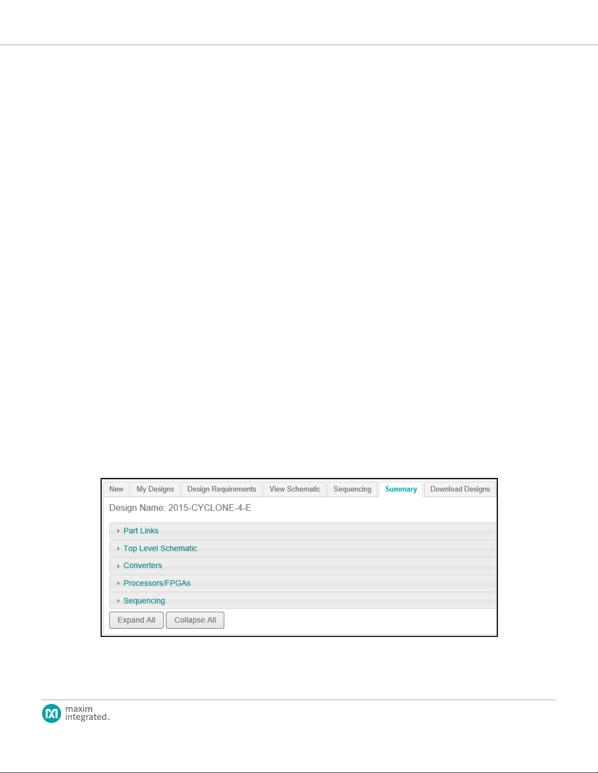
1. Open a system power design and click the Summary tab.
2. Scroll down to the bottom of the Summary page and click Collapse All.
The page shows the ve sections of the Summary page:
page 31
Page 32

EE-Sim User Guide
3. Click Part Links to expand this section and view the following data:
a. Ref Des: The abbreviated name or ID for the part as it is refer
enced in the design schematic. For example, item PS1 represents
a power supply and item U1 represents a processor.
b. Part Number: The OEM part number, model name, or generic
item name such as Power Supply.
c. Device Type: The category for the part, such as Processor/
FPGA, Sequencer, or Supply.
d. Click Data Sheet to view a multi-page PDF document with complete
part specications, commands, and other reference information.
e. Click Info to view additional online information about the part.
4. Click Top Level Schematic to expand this section and view the diagram
in read-only mode. To edit the schematic again, click View Schematic.
5. Click Converters to view the requirements for each converter used
in your schematic. If the converter was designed and simulated in the
EE-Sim DC/DC Conversion tool, those results are shown here (BOM,
schematic, waveforms, etc.)
6. Click Processors/FPGAs to expand this section. Click a processor to
expand it. Your specications from the original Design Requirements
page appear in a read-only view that includes the manufacturer, model
or family, device number, pin names, pin groups, voltages, amperes, and
supply tolerances.
7. Click Sequencing to expand this section and reveal three subsections:
a. Click Sequencer Selection to view any sequencers chosen.
b. Click Group/Rail Assignment to view these assignments.
c. Click Timing Diagram to view the timing diagrams for this device.
d. To make any changes, click the Sequencing tab.
8. Click Save to save the nal version of your design.
page 32
Page 33

EE-Sim User Guide
4.5.2 Generating and Printing a Summary Page
Follow these steps to view a web page or PDF that summarizes your design in
the following ve sections:
• Part Links
• Level Schematic
• Converters
• Processors/FPGAs
• Sequencing
1. Open a system power design.
2. For a summary page in HTML format:
a. Click the Summary tab.
b. Scroll down to the bottom of the Summary page and click Expand
All.
c. The Summary page appears showing all ve sections in your web
browser.
3. For a summary page in PDF format:
a. Click the Download Designs tab.
b. Click Download PDF to view, open, or save the Summary page
with all ve sections in a PDF le.
4. From your web browser or the PDF le, click Print to print the summary
to a printer, network copier, fax device, or to save the le as a PDF, XPS,
or other format.
4.5.3 Generating and Saving a BOM
Use this procedure to generate, view, and save a bill of materials (BOM) for a
system power design.
1. Open a system power design and click the Download Designs tab.
2. Click Download BOM.
3. Open or save the BOM as a Microsoft Excel spreadsheet le with the
following columns:
• Reference ID (matching the item identiers used in the schematic)
• Quantity
• Part Number
• Manufacturer
• Description
page 33
Page 34

EE-Sim User Guide
5 Filter Designs
Documentation for this section is not yet available. Questions can be submitted
at www.maximintegrated.com/tech-support.
page 34
Page 35

EE-Sim User Guide
6 PLL/VCO Designs
Documentation for this section is not yet available. Questions can be submitted
at www.maximintegrated.com/tech-support.
page 35
Page 36

EE-Sim User Guide
7 The EE-Sim Application for Windows
You can perform any of the following tasks with the ofine edition of EE-Sim:
• Simulate your schematic.
• Perform enhanced schematic editing, waveform viewing, and analysis.
• Use the SIMPLIS simulation engine for closed-loop switching power
supply applications.
• Run the SIMetrix Spice simulation engine.
7.1 Downloading the Desktop Edition of EE-Sim
You can download a desktop application edition of EE-Sim for ofine use on a
PC running Microsoft Windows® 8 or Windows 7.
Click the Download Designs tab.
1. Click the EE-Sim.exe link.
2. Save the le to your desktop or temporary downloads folder.
Note:AfterinstallingEE-Simofineedition,youcandeletethisle.
3. Exit all other applications.
4. Continue to the next procedure to run the installer.
7.2 Installing the Desktop Edition of EE-Sim
1. Open the EE-Sim installer application. For example, ee-sim-62e.exe. The
installation wizard appears to guide you through a series of installation
options spanning multiple pages. Click Next.
page 36
Page 37

EE-Sim User Guide
2. In the License Agreement window, scroll down to read the terms and
click I accept the terms of the license agreement. Click Print to save a
copy of the terms. To continue, click Next.
3. In the Choose Destination Location window, if you accept the default
folder destination, click Next to continue. To specify a different directory,
click Browse, navigate to another folder, and select it. Then, click Next.
page 37
Page 38

EE-Sim User Guide
4. In the Ready to Install the Program window, click Install.
5. A window appears to notify you that the installation is complete.
Click Finish.
page 38
Page 39

EE-Sim User Guide
7.3 How to Start Using the EE-Sim Application for Windows
Follow these steps after the installation to open the ofine application and get
started.
1. Click Start in Microsoft Windows and then click EE-Sim. You can also
type ee-sim into the search eld.
Windows 8 users can create a new start tile or can create desktop
shortcuts in a Quick Launch toolbar just like previous versions of
Windows.
2. In the Starting EE-Sim for the First Time message box, select the
following options:
a. Preferences from Earlier Version: This option only applies if you
had a previous version of EE-Sim installed on your PC. Click Yes
to migrate your old conguration settings or click No to start over
with new settings copied from the installer.
b. Example Files: Click Yes to install example les including schematics
and instructional materials or click No to skip this optional content.
page 39
Page 40

EE-Sim User Guide
If you click Yes for the example les, they appear in your My
Documents folder in a series of sub-folders as shown below:
c. After selecting either Yes or No, click Close.
page 40
Page 41

EE-Sim User Guide
3. At the EE-Sim startup window, click Ok.
4. To open a schematic from the small command shell window, choose
Open Schematic from the File menu. To open a schematic from the edi-
tor window, choose Open from the File menu. EE-Sim schematic les
end in either of the following extensions:
• sxsch
• wxsch
5. Click Help in the command shell window to open detailed help les.
page 41
Page 42

EE-Sim User Guide
DownloadDesigns: Click this tabwhen you arereadytodownloadyourschematic. You canalsodownloadthe offli ne
application on thispage.
EE-Sim Offline Applicat i on: Download and install thisapplicationtoconti nue yourdesign work.
Current Schematic: You candownload your designdata and schematic diagram as a .wxsch fi le for off l ine editing.
Google Chrome: Right-click thedownloadlink for your schematic and chooseSavelinkasfrom themenu. In the resultingSave
Asdialog box,you cansave thisfile in anyfolder.
InternetExplorer: Click thedownload linkforyourschematic.IntheDo youwant toopen or save... download bar, click
the Savebutton and thenchoose Saveas. In theresultingSave As dialogbox, youcan savethisfile in anyfolder.
7.4 Downloading a Schematic
In the DC/DC Conversion and Filter tools, you can download a schematic and
edit it using the ofine EE-Sim application.
1. Open a design and click the Download Designs tab.
2. Click the Download link for the current schematic.
3. Refer to the following graphic for download examples in Google Chrome
and Internet Explorer.
page 42
Page 43

EE-Sim User Guide
You can save your downloaded design schematic les in any folder including
the EE-Sim folder that is created under My Documents when you installed the
EE-Sim Windows application and example les.
page 43
Page 44

EE-Sim User Guide
Maxim Integrated cannot assume responsibility for use of any circuitry other than circuitry entirely embodied in a Maxim Integrated product. No circuit patent licenses
are implied. Maxim Integrated reserves the right to change the circuitry and specifications without notice at any time. The parametric values (min and max limits)
shown in the Electrical Characteristics table are guaranteed. Other parametric values quoted in this data sheet are provided for guidance.
Maxim Integrated 160 Rio Robles, San Jose, CA 95134 USA 1-408-601-1000
©
2014 Maxim Integrated Products, Inc. Maxim Integrated and the Maxim Integrated logo are trademarks of Maxim Integrated Products, Inc.
 Loading...