

Page 1
Corona (MAXREFDES12#) Nexys 3
Quick Start Guide
Rev 0; 4/13
Maxim Integrate d cannot a ssume responsibi lity f or use of a ny circui try oth er than circuitry entirel y embodi ed in a Maxim Integrated prod uct. No ci rcuit
patent licenses are implied. Maxim Integrated reserves the right to change the circuitry and specifications without notice at any time.
Maxim Integrated 160 Rio Robles, San Jose, CA 95134 USA 1-408-601-1000
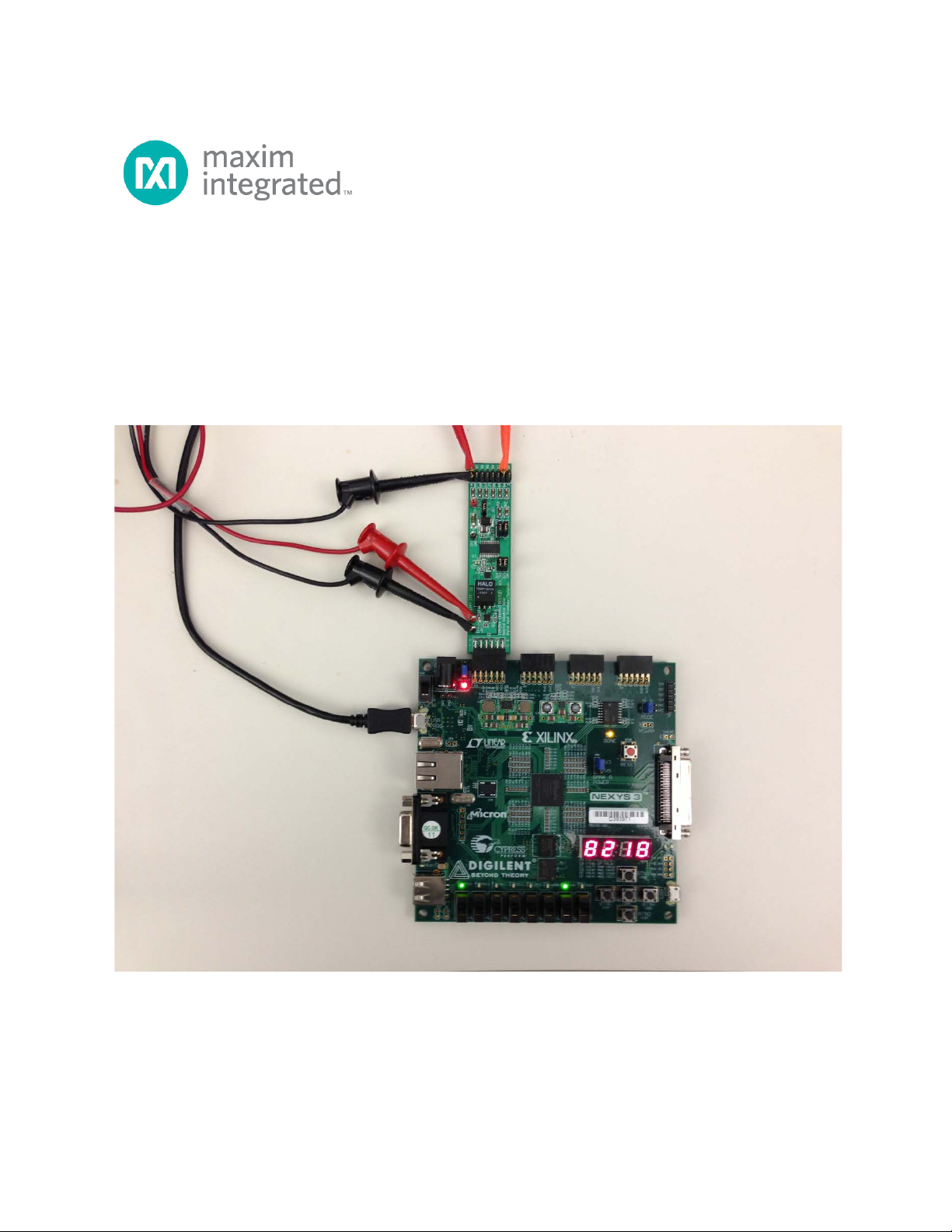
© 2013 Maxim Integrated Products, Inc. Maxim Integrated an d the Maxim Integrated logo are tradem arks of Maxim Integrated Prod uct s, Inc.
Page 2

Corona (MAXREFDES12#) Nexys 3 Quick Start Guide
Table of Contents
1. Required Equipment ................................................................................................. 3
2. Overview ................................................................................................................... 3
3. Included Files............................................................................................................ 5
4. Procedure ................................................................................................................. 6
5. Code Documentation .............................................................................................. 17
6. Appendix A: Project Structure and Key Filenames ................................................. 18
7. Trademarks............................................................................................................. 18
8. Revision History ...................................................................................................... 19
2
Page 3

Corona (MAXREFDES12#) Nexys 3 Quick Start Guide
1. Required Equipment
• PC with Windows® OS with Xilinx® ISE®/SDK version 13.4 or later and one
USB port
• License for Xilinx EDK/SDK version 13.4 or later
• Corona (MAXREFDES12#) board
• Nexys™3 development kit
• One 24V 1A DC power supply
2. Overview
Below is a high-level overview of the steps required to quickly get the Corona design
running by downloading and running the FPGA project. Detailed instructions for each
step are provided in the following pages. The Corona (MAXREFDES12#) subsystem
reference design will be referred to as Corona throughout this document.
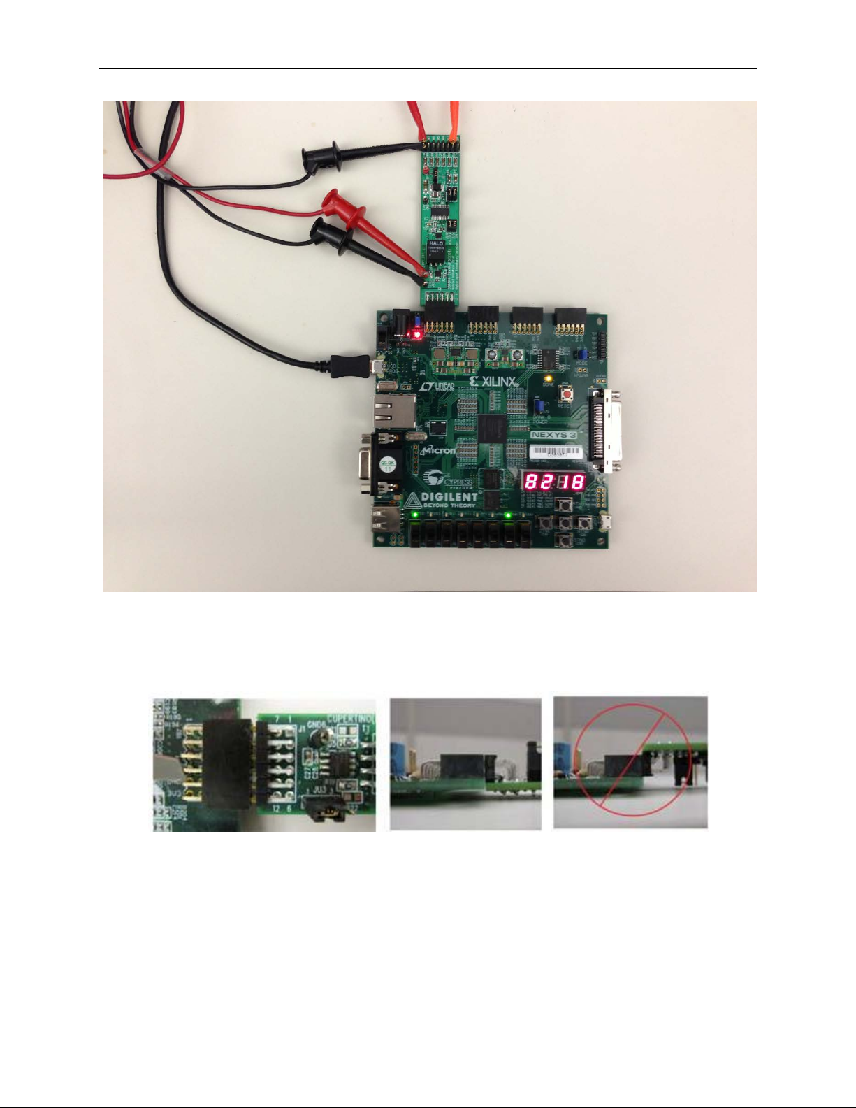
1) Connect the Corona board to the JA1 port of a Nexys 3 development kit as
shown in Figure 1
2) Download the latest RD12V01_00.ZIP file located at the Corona page.
3) Extract the RD12V01_00.ZIP file to a directory on your PC.
4) Open the Xilinx SDK.
5) Download the bitstream (.BIT) file to the board. This bitstream contains the F PGA
hardware design and software bootloader.
6) Use Xilinx SDK to download and run the executable file (.ELF) on the
MicroBlaze™.
. Ensure the connector is aligned as shown in Figure 2.
3
Page 4
Corona (MAXREFDES12#) Nexys 3 Quick Start Guide
Figure 1. Corona Board Connected to Nexys 3 Development Kit
Figure 2. Pmod™ Connector Alignment
4
Page 5
Corona (MAXREFDES12#) Nexys 3 Quick Start Guide
3. Included Files
The top level of the hardware design is a Xilinx ISE Project Navigator Project (.XISE) for
Xilinx ISE version 13.4. The Verilog-based HDL design instantiates the MicroBlaze core,
the support hardware required to run the MicroBlaze, and the peripherals that interface
to the Pmod ports. This is supplied as a Xilinx software development kit (SDK) project
that includes a demonstration software application to evaluate the Corona subsystem
reference design. The lower level c-code driver routines are portable to the user’s own
software project.
5
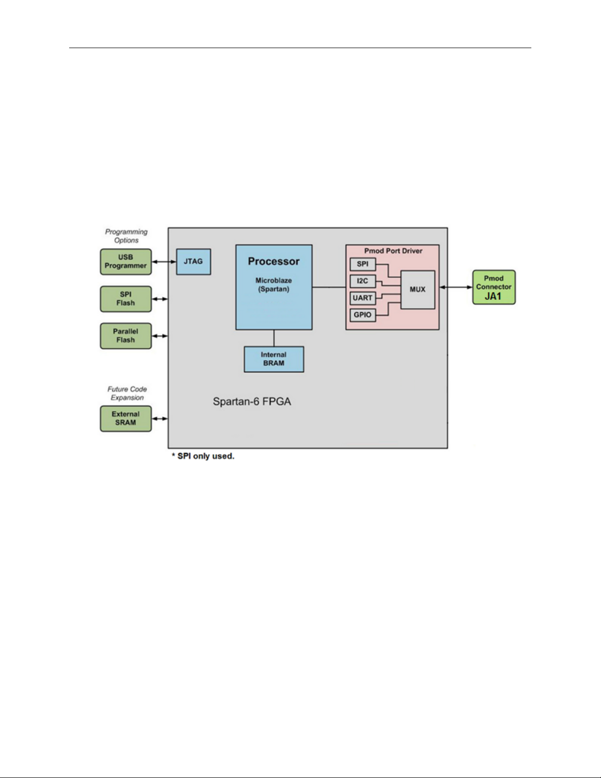
Figure 3. Block Diagram of FPGA Hardware Design
Page 6

Corona (MAXREFDES12#) Nexys 3 Quick Start Guide
4. Procedure
1. Connect the Corona board to the JA1 port of a Nexys 3 development kit as
shown in Figure 1.
2. Connect the 24V DC power-supply positive terminal to the TP3 connector on the
Corona board. Connect the 24V DC power-supply ground terminal to the TP4
connector on the Corona board.
3. Power up the Nexys 3 development kit by sliding the SW8 switch on the Nexys 3
board to the ON position.
4. Download the latest RD12V01_00.ZIP file at
www.maximintegrated.com/AN5611. All files available for downl oa d are
available at the bottom of the page.
5. Extract the RD12V01_00.ZIP file to a directory on your PC. The location is
arbitrary but the maximum path length limitation in Windows (260 characters)
should not be exceeded.
In addition, the Xilinx tools require the path to not contain any spaces.
C:\Do Not Use Spaces In The Path\RD12V01_00.ZIP
(This path has spaces.)
For the purposes of this document, it will be C:\designs\maxim\RD12V01_00\.
See Appendix A: Project Structure and Key Filenames in this document for
the project structure and key filenames.
6
Page 7
Corona (MAXREFDES12#) Nexys 3 Quick Start Guide
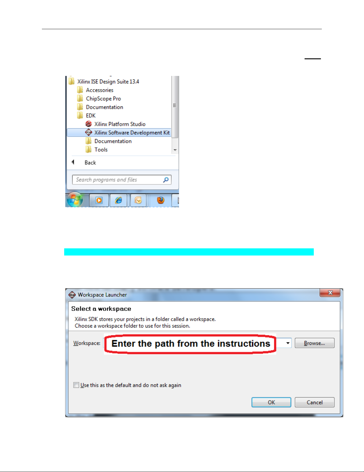
6. Open the Xilinx Software Development Kit (SDK) from the Windows Start
menu.
7. SDK will prompt for a workspace directory, which is the location where the
software project is located. For this example, it is:
C:\designs\maxim\RD12V01_00\RD12_NEXYS3_V01_00\Design_Files\sdkWorkspace
Click OK and SDK will open. The Xilinx SDK is based on an Eclipse™-based
IDE, so it will be a familiar flow for many software developers.
7
Page 8
Corona (MAXREFDES12#) Nexys 3 Quick Start Guide
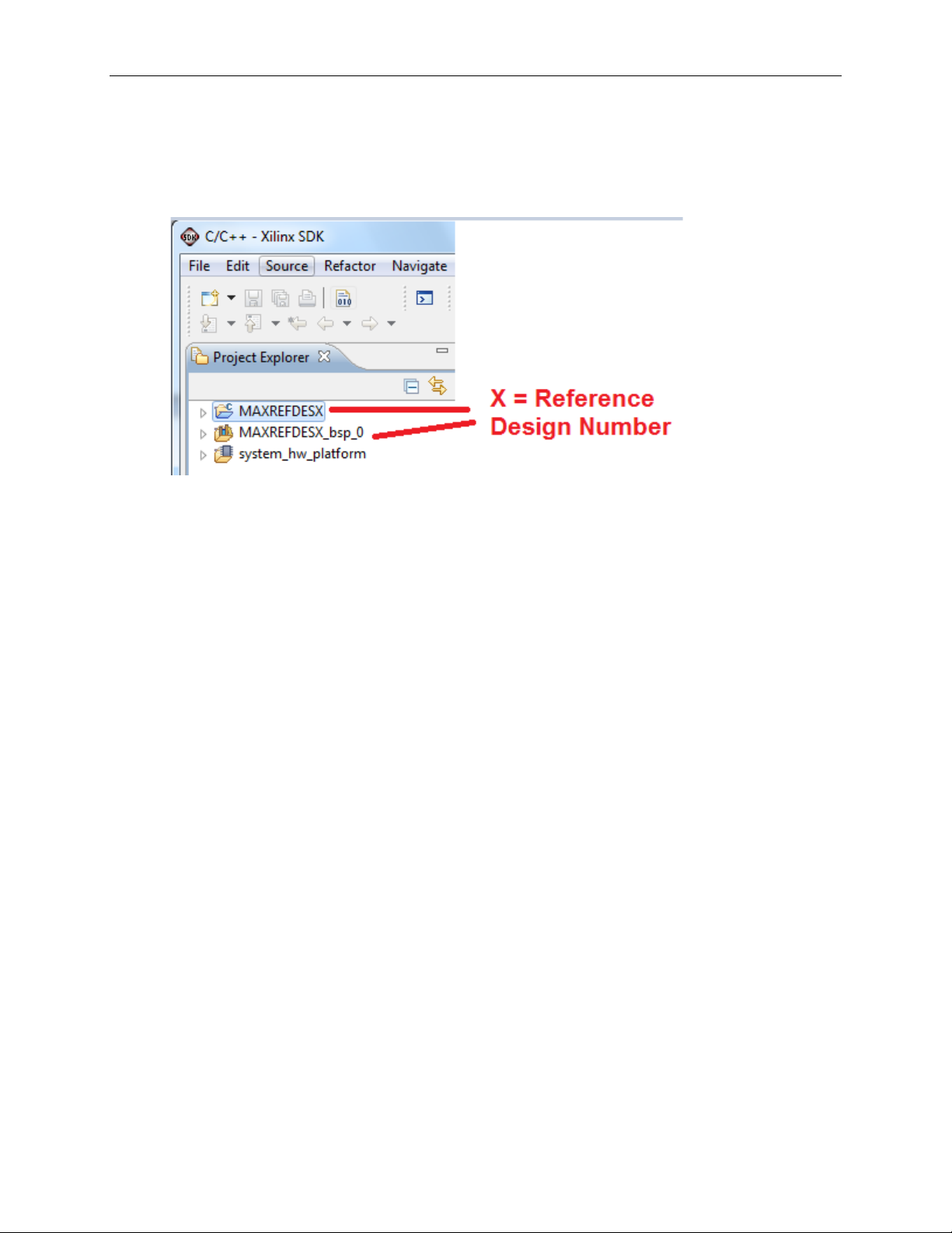
8. Review the SDK IDE. The Project Explorer in the upper left tab should have
three components as shown in the image below. If all three subfolders are
present, you can skip the next step.
8
Page 9
Corona (MAXREFDES12#) Nexys 3 Quick Start Guide
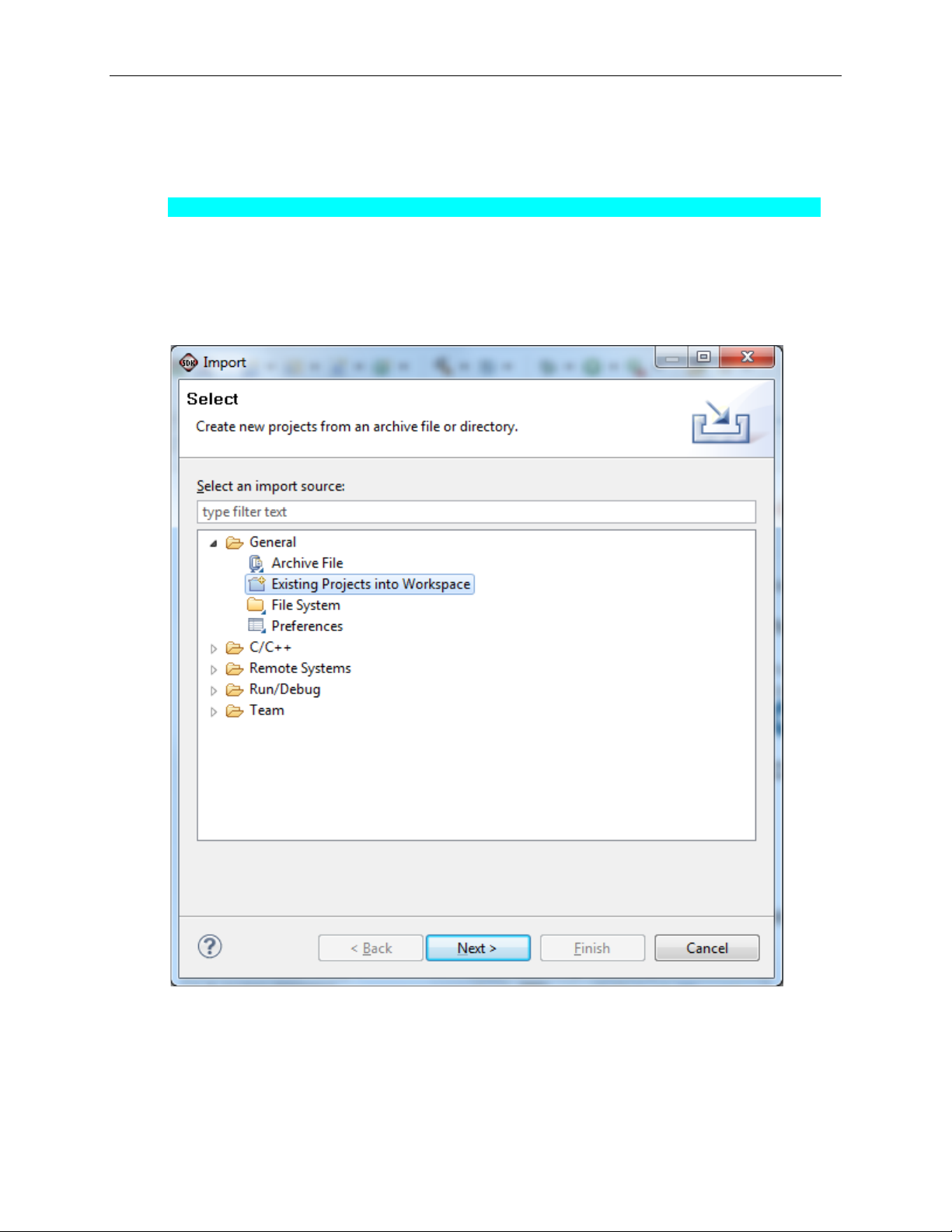
9. If the Project Explorer does not contain these three subfolders, launch the
File | Import menu, expand the General folder, and select Existing Projects
into Workspace. Click Next. Set the root directory to:
C:\designs\maxim\RD12V01_00\RD12_NEXYS3_V01_00\Design_Files\sdkWorkspace
and the missing projects should appear in SDK Project Explorer with their
checkboxes checked.
Click Finish to import the projects.
9
Page 10
Corona (MAXREFDES12#) Nexys 3 Quick Start Guide
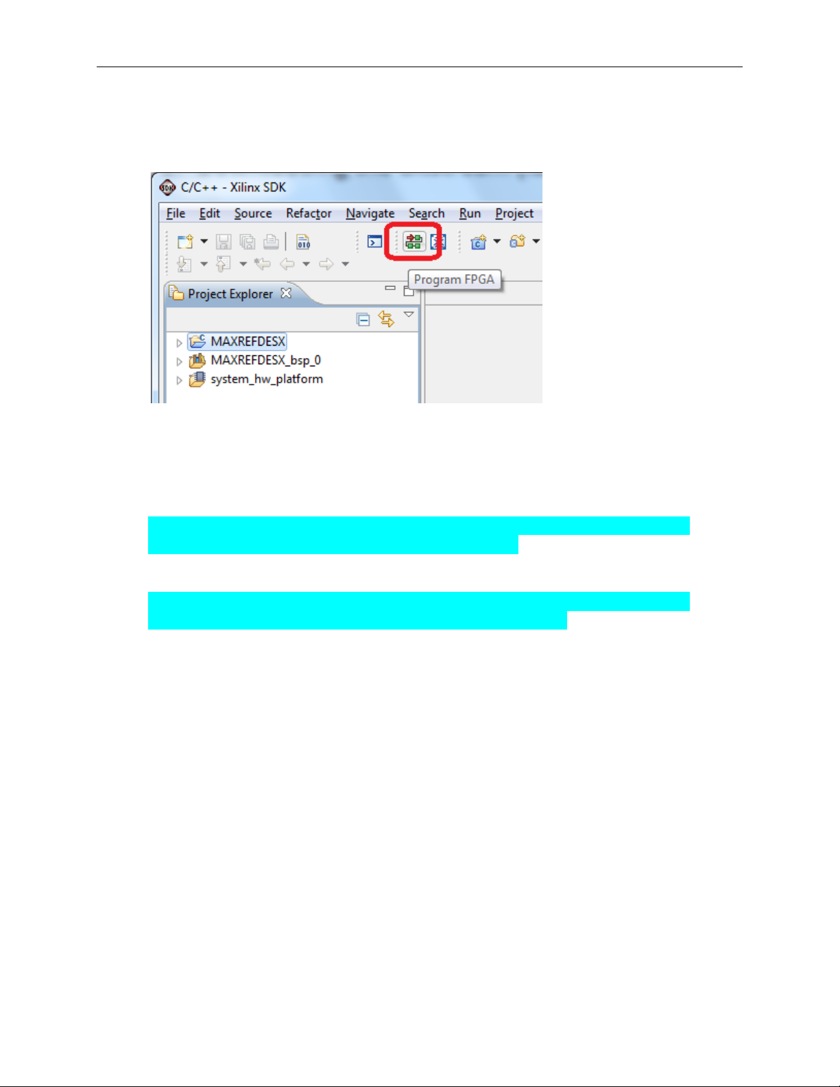
10. To download the bitstream (.BIT) file to the board, click on the Program FPGA
icon (which looks like a green chain of devices).
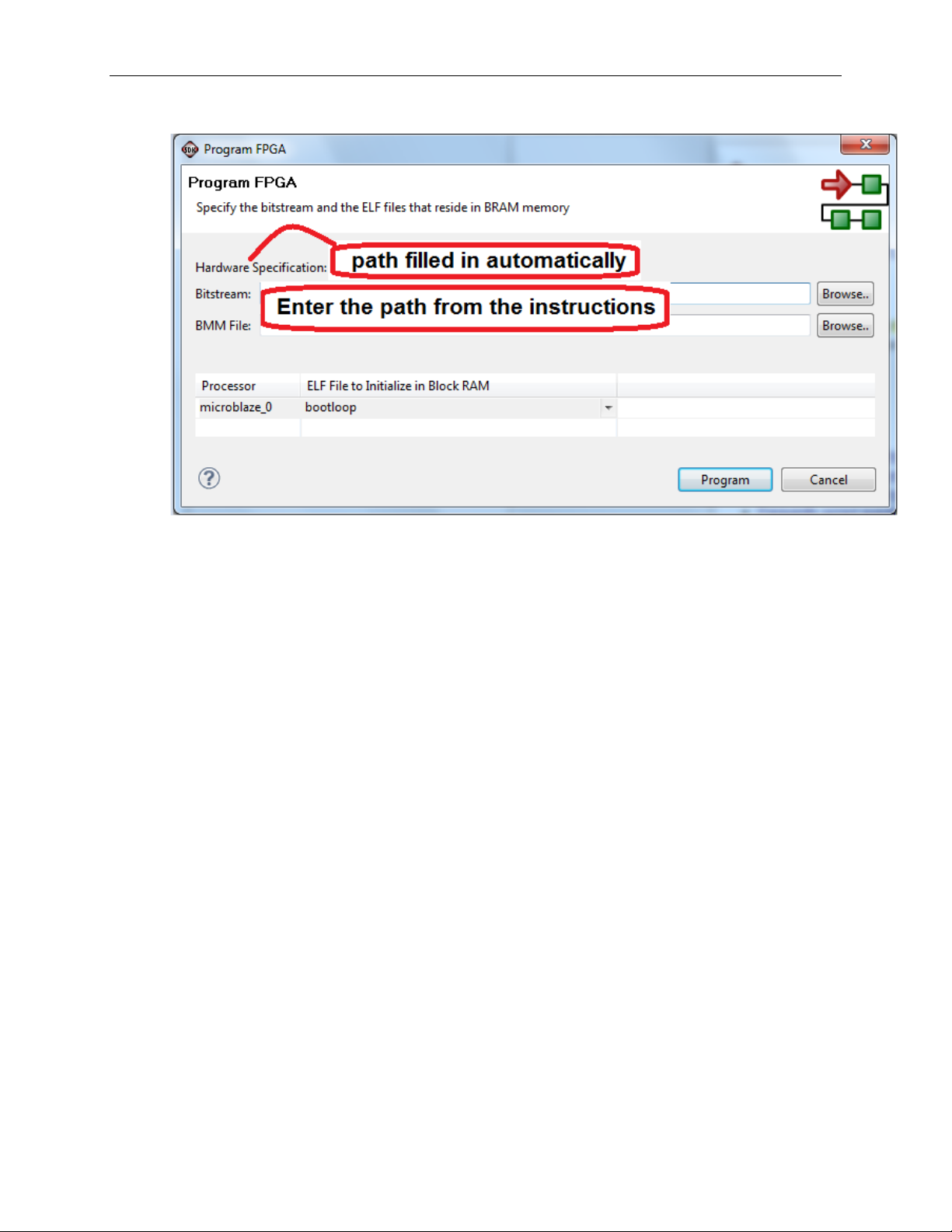
The Program FPGA dialog box appears. From here, an FPGA bitstream (.BIT)
file is selected as well as an FPGA BMM (.BMM) file. Be sure to select the .BIT
file and the .BMM by using the paths below.
Bitstream:
C:\designs\maxim\RD12V01_00\RD12_NEXYS3_V01_00\Design_Files\
sdkWorkspace\system_hw_platform\system.bit
BMM File:
C:\designs\maxim\RD12V01_00\RD12_NEXYS3_V01_00\Design_Files\
sdkWorkspace\system_hw_platform\system_bd.bmm
10
Page 11
Corona (MAXREFDES12#) Nexys 3 Quick Start Guide
Additionally, make sure bootloop is selected as shown, then press Program.
It takes approximately 10 seconds to download the FPGA, then a message box
indicating FPGA configuration complete appears.
11
Page 12
Corona (MAXREFDES12#) Nexys 3 Quick Start Guide
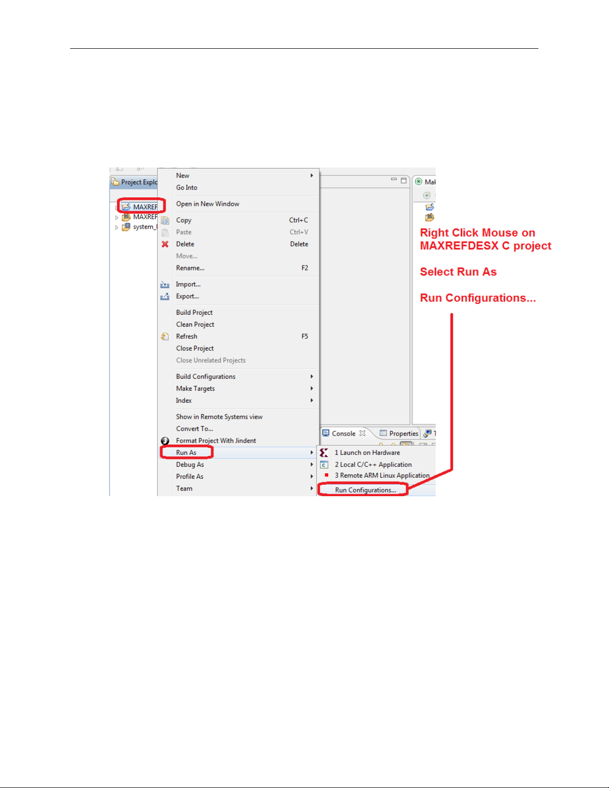
11. Use the Xilinx SDK to download and run the executable ELF (.ELF) file on the
MicroBlaze using the following steps.
Right-click the mouse while the MAXREFDES12 C project is selected, choose
the Run As menu, and then Run Configurations… menu as shown below.
12
Page 13
Corona (MAXREFDES12#) Nexys 3 Quick Start Guide
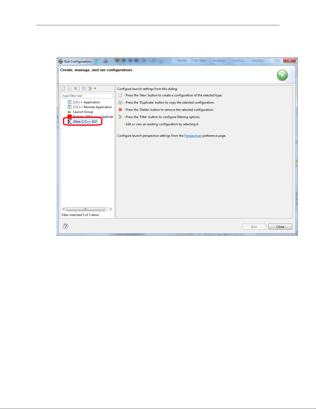
Next, double-click the mouse on the Xilinx C/C++ ELF menu.
13
Page 14
Corona (MAXREFDES12#) Nexys 3 Quick Start Guide
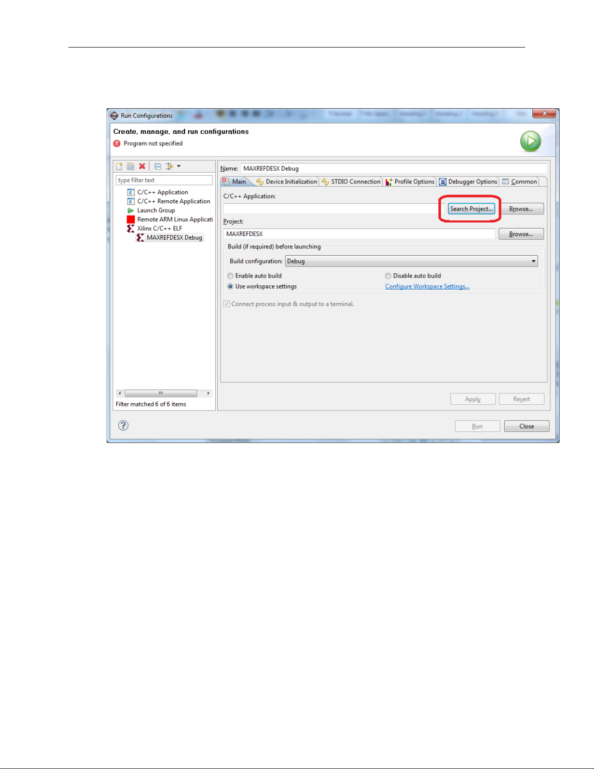
Next, press the Search Project button.
14
Page 15
Corona (MAXREFDES12#) Nexys 3 Quick Start Guide
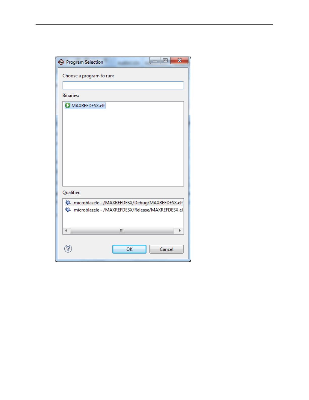
Double-click on the MAXREFDES12.elf binary.
15
Page 16
Corona (MAXREFDES12#) Nexys 3 Quick Start Guide
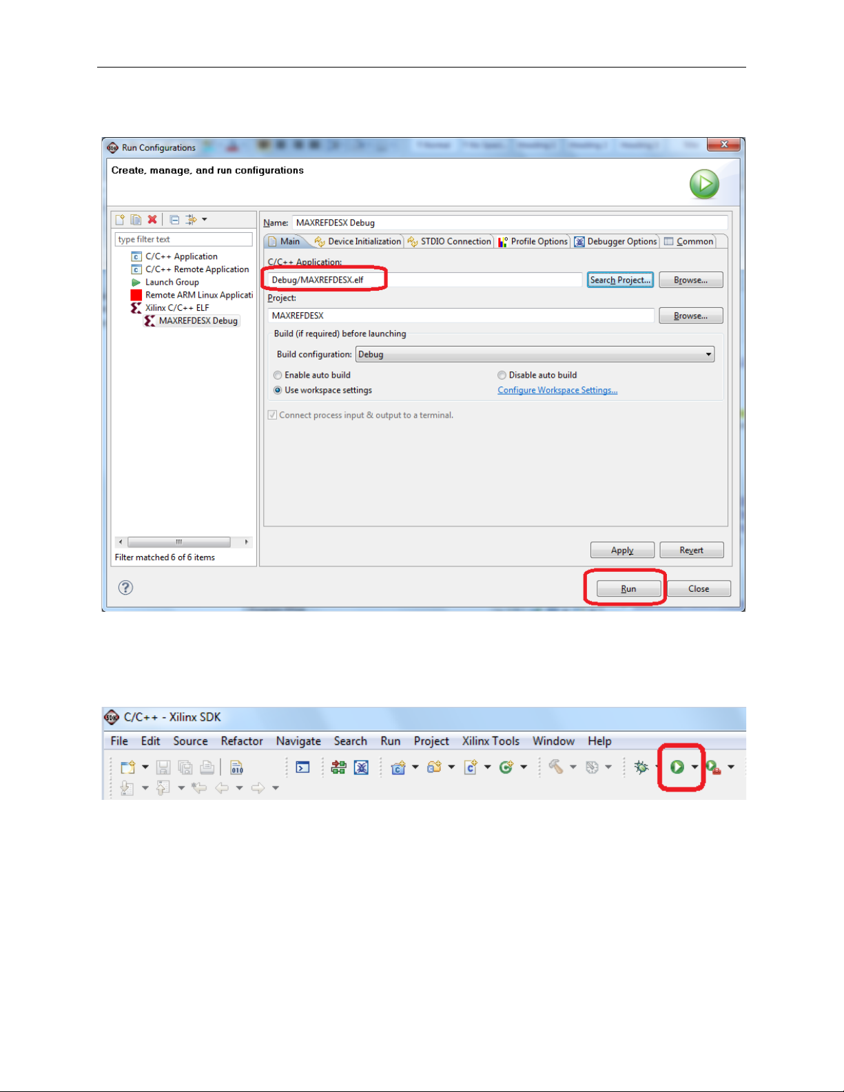
Verify the application is selected and press the Run button.
Once the Debug/MAXREFDES12 configuration is set up once, you just need to
press the Run button if you ever want to run the program again.
At this point, the application is running on the MicroBlaze. The LEDs LD7–LD0
on the Nexys 3 development board indicate the voltage levels of the digital input
channels IN8–IN0, respectively. LED ON indicates a high-v olt ag e input, LED
OFF indicates a low-voltage input. At the same time, the 7-segment LED panel
on the Nexys 3 development board displays the MAX31911 16-bit register value
in HEX format.
Change the digital input voltages to verify the register value follows the changes
properly.
16
Page 17
Corona (MAXREFDES12#) Nexys 3 Quick Start Guide
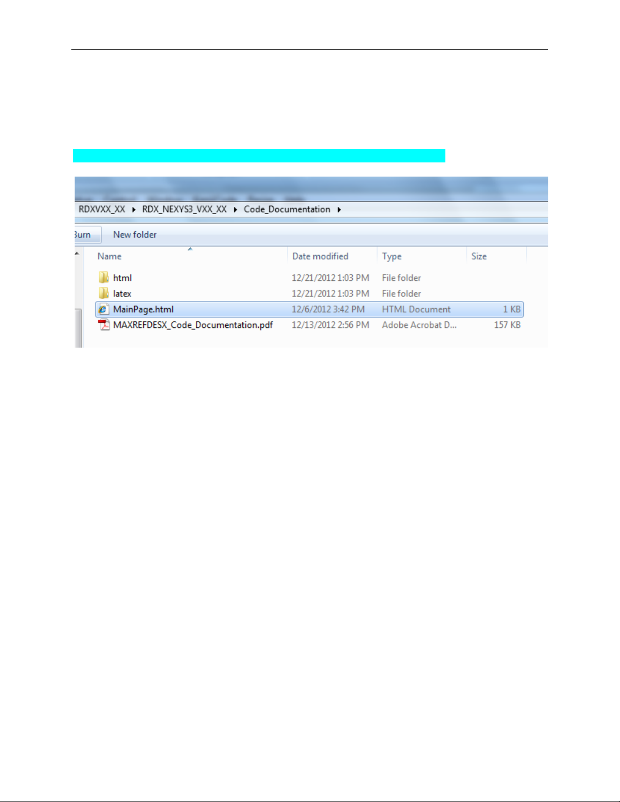
5. Code Documentation
Code documentation can be found at:
C:\...\RD12V01_00\RD12_NEXYS3_V01_00\Code_Documentation\
To view the code documentation in HTML format with a browser, open the
MainPage.html file.
To view the code documentation in .PDF format with a PDF reader, open the
MAXREFDES12_Code_Documentation.pdf file.
17
Page 18
Corona (MAXREFDES12#) Nexys 3 Quick Start Guide
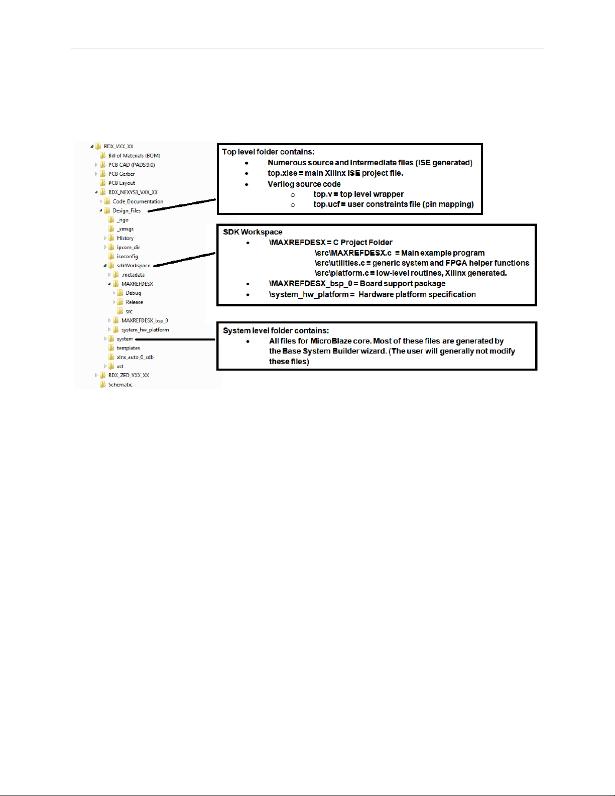
6. Appendix A: Project Struct ure and Key Filenames
7. Trademarks
Eclipse is a trademark of Eclipse Foundation, Inc.
ISE is a registered trademark of Xilinx, Inc.
MicroBlaze is a trademark of Xilinx, Inc.
Nexys is a trademark of Digilent Inc.
Pmod is a trademark of Digilent Inc.
Spartan is a registered trademark of Xilinx, Inc.
Windows is a registered trademark and registered service mark and Windows XP is a
registered trademark of Microsoft Corporation.
Xilinx is a registered trademark and registered service mark of Xilinx, Inc.
18
Page 19

8. Revision Histor y
REVISION
NUMBER
REVISION
DATE
PAGES
CHANGED
0
4/13
Initial release
⎯
Corona (MAXREFDES12#) Nexys 3 Quick Start Guide
DESCRIPTION
19
 Loading...