

Page 1
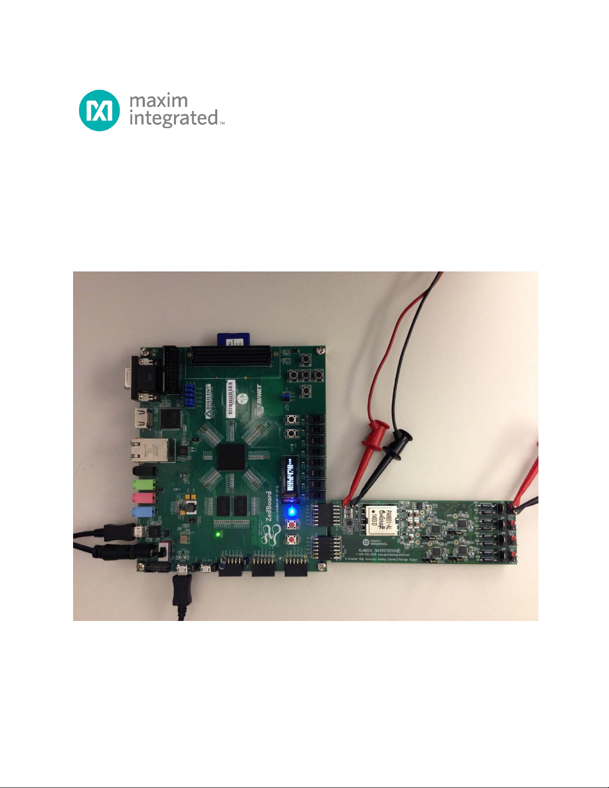
Alameda (MAXREFDES24#) ZedBoard
Quick Start Guide
Rev 0; 3/14
Maxim Integrated cannot assume responsibility for use of any circuitry other than circuitry entirely embodied in a Maxim Integrated product. No circuit
patent licenses are implied. Maxim Integrated reserves the right to change the circuitry and specifications without notice at any time.
Maxim Integrated 160 Rio Robles, San Jose, CA 95134 USA 1-408-601-1000
© 2014 Maxim Integrated Products, Inc. Maxim Integrated and the Maxim Integrated logo are trademarks of Maxim Integrated Products, Inc.
Page 2

Alameda (MAXREFDES24#) ZedBoard Quick Start Guide
Table of Contents
1. Required Equipment ................................................................................................. 3
2. Overview ................................................................................................................... 3
3. Included Files ........................................................................................................... 5
4. Procedure ................................................................................................................. 6
5. Code Documentation .............................................................................................. 19
6. Appendix A: Project Structure and Key Filenames ................................................. 20
7. Trademarks ............................................................................................................ 20
8. Revision History ...................................................................................................... 21
2
Page 3

Alameda (MAXREFDES24#) ZedBoard Quick Start Guide
1. Required Equipment
• PC with Windows® OS with Xilinx® ISE®/SDK version 14.2 or later and two USB
ports (Refer to Xilinx AR# 52495 if you installed ISE WebPACKTM design
software on your PC.)
• License for Xilinx EDK/SDK version 14.2 or later (free WebPACK license is OK)
• Alameda (MAXREFDES24#) board
• ZedBoardTM development kit
• One +24V 1A DC power supply
• One 750Ω 0.25W resistor
2. Overview
Below is a high-level overview of the steps required to quickly get the Alameda design
running by downloading and running the FPGA project. Detailed instructions for each
step are provided in the following pages. The Alameda (MAXREFDES24#) subsystem
reference design will be referred to as Alameda throughout this document.
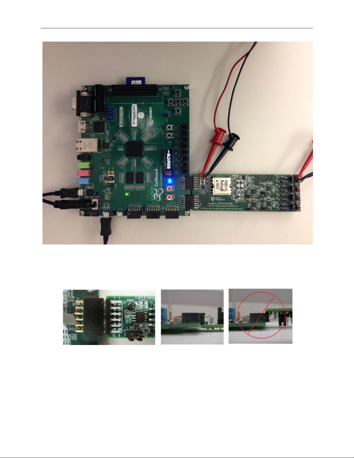
1) Connect the Alameda board to the JA1 and JB1 ports of a ZedBoard as shown in
Figure 1. Ensure the connectors are aligned as shown in Figure 2
communication between the Alameda board and the ZedBoard is through the
pins on the JB1 connector. The JA1 connector is for the board physical support
only.
2) Download the latest RD24V01_00.ZIP file located at the Alameda page.
3) Extract the RD24V01_00.ZIP file to a directory on your PC.
4) Open the Xilinx SDK.
5) Download the bitstream (.BIT) file to the board. This bitstream contains the FPGA
hardware design and software bootloader.
6) Use Xilinx SDK to download and run the executable file (.ELF) on one of the two
ARM® CortexTM -A9 processors.
. The
3
Page 4
Alameda (MAXREFDES24#) ZedBoard Quick Start Guide
Figure 1. Alameda Board Connected to ZedBoard Kit
Figure 2. Pmod™ Connector Alignment
4
Page 5
Alameda (MAXREFDES24#) ZedBoard Quick Start Guide
3. Included Files
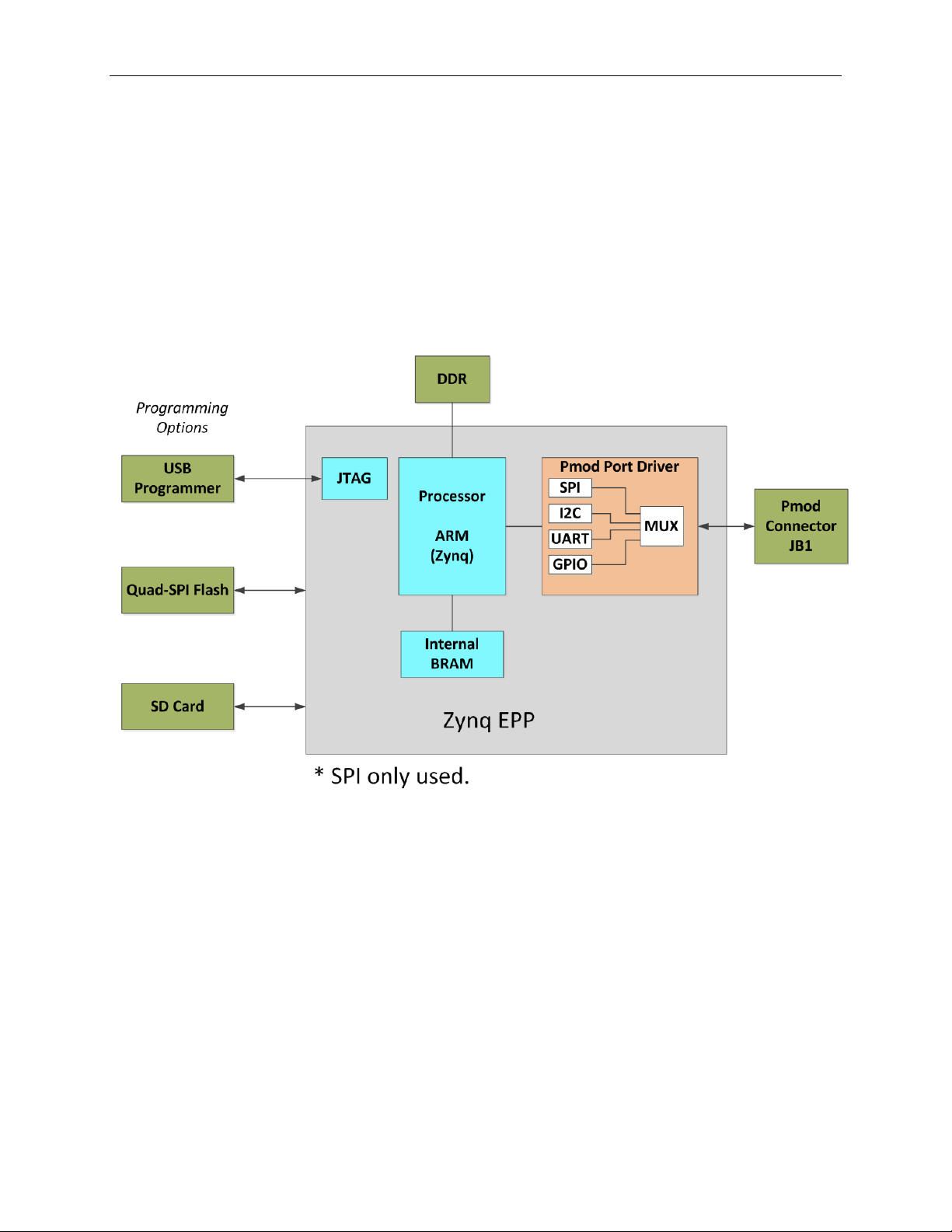
The top level of the hardware design is a Xilinx ISE Project Navigator Project (.XISE) for
Xilinx ISE version 14.2. The Verilog-based top.v module provides FPGA/board net
connectivity, allows HDL interaction with peripherals, a nd instantiates the wrapper that
carries both the Zynq® Processing System and (I2C, SPI, GPIO, UART) soft peripherals
that inter face to the Pmod ports. This is supplied as a Xilinx software development kit
(SDK) project that includes a demonstration software application to evaluate the
Alameda subsystem reference design. The lower level c-code driver routines are
portable to the user’s own software project.
5
Figure 3. Block Diagram of FPGA Hardware Design
Page 6

Alameda (MAXREFDES24#) ZedBoard Quick Start Guide
4. Procedure
1. Connect the Alameda board to the JA1 and JB1 ports of a ZedBoard as shown in
Figure 1.
2. Connect the +24V power supply positive terminal and the ground terminal to the
+24V and the PGND connectors on the Alameda board, respectively.
3. Connect one end of the 750Ω load resistor to the OUT1 connector on the
Alameda board. Connect the other end of the 750Ω load resistor to the AGND1
connector on the Alameda board.
4. Ver if y t hat the JU1, JU3, JU5, and JU7 jumpers are on the 2-3 position.
5. Ver if y t hat the JU2, JU4, JU6, and JU8 jumpers are on the 1-2 position.
6. Connect the J14 USB connector of the ZedBoard to a PC. This connection is
used to communicate with a PC through a terminal program. See step 16 for
USB driver installation.
7. Connect the J17 USB connector of the ZedBoard to a PC. This connection is
used to program and debug the FPGA.
8. Power up t he ZedBoard by sliding the SW8 switch on the ZedBoard to the ON
position.
9. Download the latest RD24V01_00.ZIP file at
www.maximintegrated.com/Alameda. All files available for download are
available at the bottom of the page.
10. Extract the RD24V01_00.ZIP file to a directory on your PC. The location is
arbitrary but the maximum path length limitation in Windows (260 characters)
should not be exceeded.
In addition, the Xilinx tools require the path to not contain any spaces.
C:\Do Not Use Spaces In The Path\RD24V01_00.ZIP
(This path has spaces.)
For the purposes of this document, it will be C:\designs\maxim\RD24V01_00\.
See Appendix A: Project Structure and Key Filenames in this document for
the project structure and key filenames.
6
Page 7
Alameda (MAXREFDES24#) ZedBoard Quick Start Guide
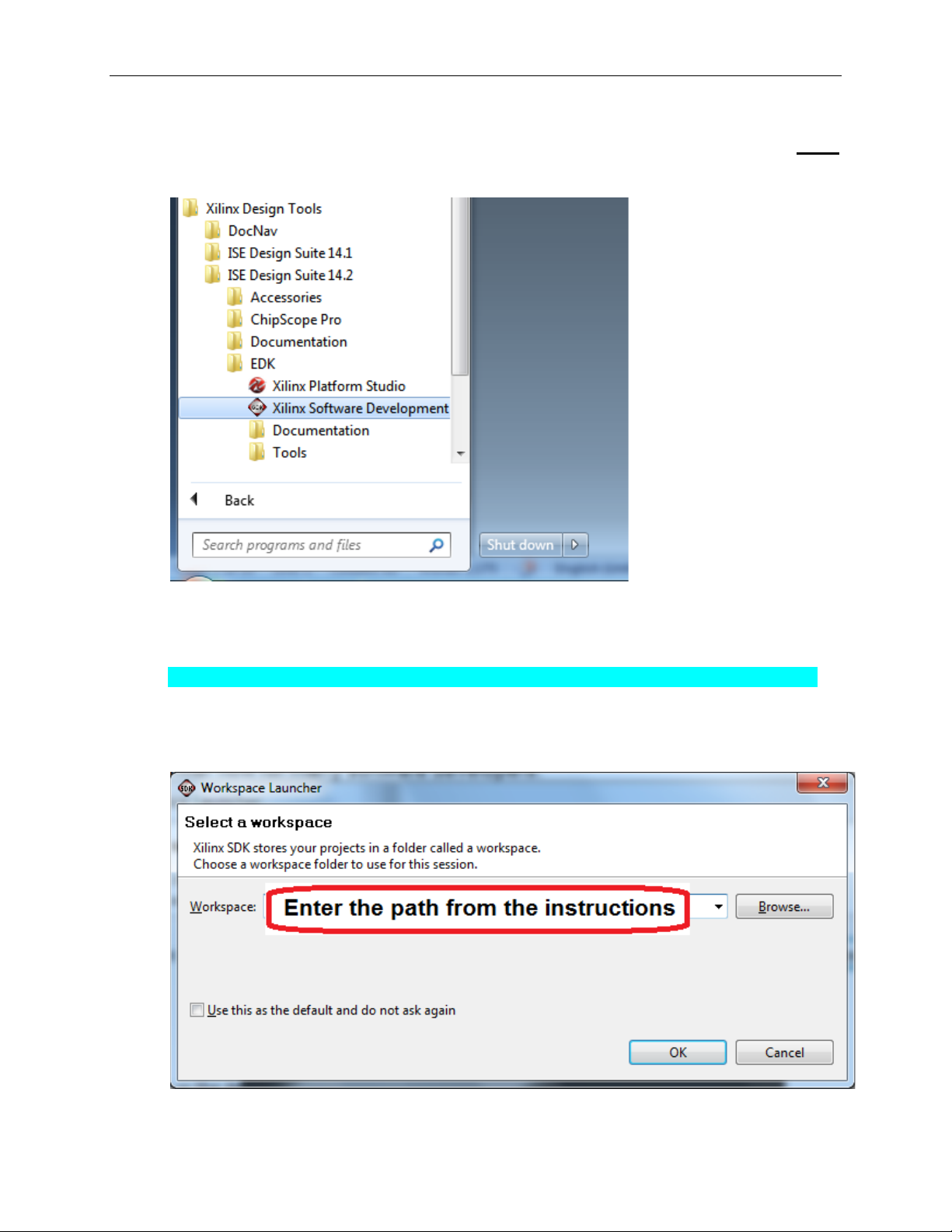
11. Open the Xilinx Software Development Kit (SDK) from the Windows Start
menu.
12. SDK will prompt for a workspace directory, which is the location where the
software project is located. For this example, it is:
C:\designs\maxim\RD24V01_00\RD24_ZED_V01_00\Design_Files\sdkWorkspace
Click OK and SDK will open. The Xilinx SDK is based on an Eclipse™-based
IDE, so it will be a familiar flow for many software developers.
7
Page 8

Alameda (MAXREFDES24#) ZedBoard Quick Start Guide
13. Review the SDK IDE. The Project Explorer in the upper left tab should have
three components as shown in the image below. If all three subfolders are
present, you can skip the next step.
8
Page 9

Alameda (MAXREFDES24#) ZedBoard Quick Start Guide
14. If the Project Explorer does not contain these three subfolders, launch the
File | Import menu, expand the General folder, and select Existing Projects
into Workspace. Click Next. Set the root directory to:
C:\designs\maxim\RD24V01_00\RD24_ZED_V01_00\Design_Files\sdkWorkspace
and the missing projects should appear in SDK Project Explorer with their
checkboxes checked.
Click Finish to import the projects.
9
Page 10

Alameda (MAXREFDES24#) ZedBoard Quick Start Guide
15. To download the bitstream (.BIT) file to the board, click on the Program FPGA
icon (which looks like a green chain of devices).
The Program FPGA dialog box appears. From here, an FPGA Bitstream (.bit)
file is selected. Be sure to select the .bit file by using the path below.
Bitstream:
C:\designs\maxim\RD24V01_00\RD24_ZED_V01_00\Design_Files\top.bit
Press Program.
10
It takes approximately 10 seconds to download the FPGA, then a message box
indicating FPGA configuration complete appears.
Page 11

Alameda (MAXREFDES24#) ZedBoard Quick Start Guide
16. Set up the terminal program to run on the PC using the following steps. Before
loading the executable firmware file on the FPGA, the terminal program on the
PC should be running. The example firmware running on the FPGA
communicates with the PC via a USB port set up to emulate a serial port (UART).
To establish this communication link, the PC must be configured with the
appropriate Windows drivers. A suitable terminal program such as Ter a Term or
HyperTerminal should be invoked.
The ZedBo ard utilizes the Cypress USB-UART bridge IC. If the Windows cannot
automatically install the driver for the Cypress USB-UART bridge IC, the dr iver is
available for download from (www.cypress.com/?rID=63794). The driver is
WHQL certified for the default Cypress VID / PID of 0x04B4 / 0x0008.
Once installed, Windows will assign a previously unused COM port. Use the
Windows Control Panel | System | Device Manager to determine the COM port
number. (It will be named Cypress Serial.) Make a note of which COM port this
is. That information is needed in the next step.
Next, a terminal emulation program needs to be installed and launched. For
Windows XP® and earlier systems, the HyperTerminal program is the usual
choice. However, since HyperTerminal was eliminated from Windows 7, it may
be necessary to locate an alternative. Several are available; one good choice is
called Tera Term (http://ttssh2.sourceforge.jp/). Whatever terminal program you
choose, the communication sho uld be set up by opening the COM port number
previously described above and the port configured as:
bits per second: 460,800;
data bits: 8;
parity: none;
stop bits: 1;
flow control: none.
11
Page 12

Alameda (MAXREFDES24#) ZedBoard Quick Start Guide
17. Use the Xilinx SDK to download and run the executable ELF (.ELF) file on the
ARM Cortex-A9 processor using the following steps.
Right-click the mouse while the MAXREFDES24 C project is selected, choose
the Run As menu, and then Run Configurations… menu as shown below.
12
Page 13

Alameda (MAXREFDES24#) ZedBoard Quick Start Guide
Next, double-click the mouse on the Xilinx C/C++ ELF menu.
13
Page 14

Alameda (MAXREFDES24#) ZedBoard Quick Start Guide
Next, press the Search Project button.
14
Page 15

Alameda (MAXREFDES24#) ZedBoard Quick Start Guide
Double-click on the MAXREFDES24.elf binary.
15
Page 16

Alameda (MAXREFDES24#) ZedBoard Quick Start Guide
Verify the application is selected on the Main tab.
16
Page 17

Alameda (MAXREFDES24#) ZedBoard Quick Start Guide
On the Device Initialization tab, click Browse… button to select the right
initialization TCL file and press the Run button.
Once the Debug/MAXREFDES24 configuration is set up once, you just need to
press the Run button if you ever want to run the program again.
17
Page 18

Alameda (MAXREFDES24#) ZedBoard Quick Start Guide
At this point, the application will be running on the Cortex-A9 and the terminal
program should show the menu below. Make the desired selections by pressing
the appropriate keys on the keyboard. For example, to select current output,
press 0.
18
Page 19

Alameda (MAXREFDES24#) ZedBoard Quick Start Guide
5. Code Documentation
Code documentation can be found at:
C:\...\RD24V01_00\RD24_ZED_V01_00\Code_Documentation\
To view the code documentation in HTML format with a browser, open the
MainPage.html file.
To view the code documentation in .PDF format with a PDF reader, open the
MAXREFDES24_Code_Documentation.pdf file.
19
Page 20

Alameda (MAXREFDES24#) ZedBoard Quick Start Guide
6. Appendix A: Project Structure and Key Filenames
7. Trademarks
ARM is a registered trademark of ARM Ltd.
Cortex is a trademark of ARM Ltd.
Eclipse is a trademark of Eclipse Foundation, Inc.
ISE is a registered trademark of Xilinx, Inc.
MicroBlaze is a trademark of Xilinx, Inc.
Pmod is a trademark of Digilent, Inc.
WebPACK is a trademark of Xilinx, Inc.
Windows is a registered trademark and registered service mark and Windows XP is a
registered trademark of Microsoft Corporation.
Xilinx is a registered trademark and registered service mark of Xilinx, Inc.
ZedBoard is a trademark of ZedBoard.org.
Zynq is a registered trademark of Xilinx, Inc.
20
Page 21

Alameda (MAXREFDES24#) ZedBoard Quick Start Guide
REVISION
NUMBER
REVISION
DATE
PAGES
CHANGED
8. Revision History
DESCRIPTION
0 3/14 Initial release —
21
 Loading...