

Page 1

Simplifying System Integration
TM
73M1822/73M1922
Control Module User Guide
Decem b er 2 3, 20 09
Rev. 1.0
UG_1x22_053
Page 2

73M1822/73M1922 Control Module User Guide UG_1x22_053
© 20 09 Teridian Semiconductor Cor poration. All rights rese r ved.
Terid i an Semiconductor Corp or ation is a registered trademark of Teridian Semiconductor Cor poration.
Simplifying Syst em Integrat i on is a trademark of Teridian Semi condu ct or Corporat ion .
Linux is a regist er ed trademark of Linu s Torvalds.
Asterisk i s a registered trademark of Digium , Inc.
All other t r ademar ks are the property of their respective owners.
Terid i an Semiconductor Corpor ation makes no warrant y for the use of i ts pr oducts, other than expr essly
contained in the Company’s warranty detailed in the Teridian Semiconduct or C or poration standard Terms
and C onditi ons. The company assumes no respon sibility for any errors which may appear in this
document, reserves the right to change devices or specifi cations detailed herein at any tim e without
notice and does not make any co mm i tment to update the information contained herein. Accordingly, the
reader is cautioned to veri fy that th i s document is curren t by compari ng it to th e l atest version on
http://w w w. teridian.com or by checking with your sales represen tative .
Teridian Semiconductor Corp., 6440 Oak Can yon, Suite 100, Irvine, CA 92618
TEL (714) 508-8800, FAX (714) 508-8877, http://www.teridian.com
2 Rev. 1.0
Page 3

UG_1x22_053 73M1822/73M1922 Control Module User Guide
Table of Contents
1 Introduction ................................................................................................................................... 7
1.1 Pu r pose an d Scope ................................................................................................................. 7
1.2 Conventions Used in this Guide ............................................................................................... 7
1.3 Acronyms................................................................................................................................. 7
2 Overview ........................................................................................................................................ 8
2.1 Driver Architectu re ................................................................................................................... 8
2.2 Functional Overview ................................................................................................................ 9
2.2.1 Event Gener ation ...................................................................................................... 10
2.2.2 Modem Channel Confi guration and Management ...................................................... 10
2.2.3 Line State Analysi s via Current and Voltage Measurements....................................... 10
2.2.4 GPIO Suppor t ............................................................................................................ 11
2.2.5 Loop back and Testing Modes .................................................................................... 12
2.2.6 Call P r ogress M onitor ................................................................................................ 12
2.2.7 Billing Tone Filter....................................................................................................... 12
3 Driver Serv i ce In t erface ............................................................................................................... 13
3.1 Linux Ope r a t i ng Sy st em ......................................................................................................... 13
3.2 Other Operating Systems ....................................................................................................... 13
4 Country Specific Settings ........................................................................................................... 14
5 Modem Events ............................................................................................................................. 15
5.1 M1X22_MDM_EVENT_t ........................................................................................................ 15
5.2 Event Identification ................................................................................................................. 16
5.2.1 M1X22_BATTERY_DROPPED ................................................................................. 16
5.2.2 M1X22_BATTERY_FEEDED .................................................................................... 16
5.2.3 M1X22_APOH_DETECT ........................................................................................... 16
5.2.4 M1X22_NOPOH_DETECT ........................................................................................ 17
5.2.5 M1X22_POLARITY_CHG .......................................................................................... 17
5.2.6 M1X22_RING_DETECT ............................................................................................ 17
5.2.7 M1X22_RING_DETECT_END ................................................................................... 18
5.2.8 M1X22_SYNC_LOSS_DETECT ................................................................................ 18
5.2.9 M1X22_OV_DETECT ................................................................................................ 18
5.2.10 M1X22_OI_DETECT ................................................................................................. 19
5.2.11 M1X22_LINE_STATE ................................................................................................ 19
5.2.12 M1X22_DIAL_COMPLETE ........................................................................................ 19
5.2.13 M1X22_DIAL_ABORTED .......................................................................................... 20
5.2.14 M1X22_SYNC_RECOVERED ................................................................................... 20
5.2.15 M1X22_GPIO_INTERRUPT ...................................................................................... 20
6 IOCTL Commands Description ................................................................................................... 21
6.1 Initialization and Configuration IOCTLs................................................................................... 21
6.1.1 M1X22_CH_INIT ....................................................................................................... 22
6.1.2 M1X22_CNTRY_NMBR_GET ................................................................................... 23
6.1.3 M1X22_GET_COUNTRY_CONFIG ........................................................................... 24
6.1.4 M1X22_SET_COUNTRY_CONFIG ........................................................................... 25
6.1.5 M1X22_PHONE_VOLUME_SET ............................................................................... 26
6.1.6 M1X22_SET_SAMPLING_FREQ .............................................................................. 27
6.1.7 M1X22_GET_SAMPLING_FREQ .............................................................................. 28
6.2 Events and Status Service ..................................................................................................... 29
6.2.1 M1X22_RNG_GET .................................................................................................... 29
6.2.2 M1X22_POL_GET .................................................................................................... 30
6.2.3 M1X22_BAT_GET ..................................................................................................... 31
6.2.4 M1X22_POH_GET .................................................................................................... 32
6.2.5 M1X22_EVENT_GET ................................................................................................ 33
6.2.6 M1X22_ERROR_CODE_GET ................................................................................... 34
Rev. 1.0 3
Page 4

73M1822/73M1922 Control Module User Guide UG_1x22_053
6.3 Modem Hook S witch Control Services .................................................................................... 35
6.3.1 M1X22_ENNOM_DELAY_TIMER.............................................................................. 35
6.3.2 M1X22_ATH1 ............................................................................................................ 36
6.3.3 M1X22_ATH0 ............................................................................................................ 37
6.3.4 M1X22_ATDP ........................................................................................................... 38
6.3.5 M1X22_ATDP_CANCEL ........................................................................................... 39
6.3.6 M1X22_ATDP_PARAM ............................................................................................. 40
6.3.7 M1X22_FLSH_CFG .................................................................................................. 41
6.3.8 M1X22_FLSH_SET ................................................................................................... 41
6.3.9 M1X22_SEND_WETTING_PULSE............................................................................ 42
6.4 Caller-ID S er vices .................................................................................................................. 43
6.4.1 M1X22_ENABLE_CALLER_ID .................................................................................. 43
6.4.2 M1X22_DISABLE_CALLER_ID ................................................................................. 44
6.4.3 M1X22_ENTER_CID_MODE .................................................................................... 44
6.4.4 M1X22_EXIT_CID_MODE......................................................................................... 45
6.5 Ring Detection Services ......................................................................................................... 46
6.5.1 M1X22_SET_MIN_INTER_RING_GAP ..................................................................... 46
6.5.2 M1X22_SET_RING_MIN_FREQ ............................................................................... 47
6.5.3 M1X22_SET_RING_MAX_FREQ .............................................................................. 47
6.6 Line State Analysi s Services .................................................................................................. 48
6.6.1 M1X22_MEASURE_START ...................................................................................... 48
6.6.2 M1X22_MEASURE_STOP ........................................................................................ 49
6.6.3 M1X22_MEASURE_UPDATE ................................................................................... 50
6.7 GPIO Services ....................................................................................................................... 52
6.7.1 M1X22_GPIO_CONFIG ............................................................................................ 52
6.7.2 M1X22_GPIO_CONTROL ......................................................................................... 53
6.7.3 M1X22_GPIO_DATA ................................................................................................. 54
6.8 Loop back Services................................................................................................................. 55
6.8.1 M1X22_LOOPBACK ................................................................................................. 55
6.9 Miscellaneous ........................................................................................................................ 56
6.9.1 M1X22_THRESHOLD_OVERRIDE ........................................................................... 56
6.9.2 M1X22_BTONE_FILTER ........................................................................................... 57
6.9.3 M1X22_CPROG_MONITOR ..................................................................................... 58
6.9.4 M1X22_DEBUG_LEVEL_SET ................................................................................... 59
7 Type and St ru ct u r e D ef in it i on R ef er ence ................................................................................... 60
7.1 M1X22_COUNTRY_CODE .................................................................................................... 60
7.2 M1X22_CNTRY_STRUCT_t .................................................................................................. 62
7.3 M1X22_DEBUG_TRACE_MASK ........................................................................................... 63
7.4 M1X22_LAST_ERROR_CODE .............................................................................................. 63
7.5 struct txrx_gain ...................................................................................................................... 64
7.6 M1X22_PULSE_DIAL_t ......................................................................................................... 64
7.7 M1X22_PULSE_DIAL_PARAM_t ........................................................................................... 65
7.8 M1X22_THRESH_OVERRIDE_t ............................................................................................ 65
7.9 M1X22_SAMPLE_RATE_SELECTION .................................................................................. 66
7.10 Billing Tone F ilter Related Data Type and Structure ............................................................... 68
7.10.1 M1X22_BTONE_FILTER_COMMAND ...................................................................... 68
7.10.2 M1X22_BTONE_FREQUENCY ................................................................................. 68
7.10.3 M1X22_BTONE_FILTER_t ........................................................................................ 69
7.11 Call Progress Monitor D ata Type and Structure ...................................................................... 70
7.11.1 M1X22_CPROG_MON_VOLT_REF .......................................................................... 70
7.11.2 M1X22_CPROG_MON_GAIN ................................................................................... 70
7.11.3 M1X22_CPROG_MONITOR_t................................................................................... 71
7.12 GPIO Related D ata Type and Structur es ................................................................................ 72
7.12.1 M1X22_GPIO_NUMBER ........................................................................................... 72
7.12.2 M1X22_GPIO_CONFIG_COMMAND ........................................................................ 72
7.12.3 M1X22_GPIO_CONTROL_TYPE .............................................................................. 73
7.12.4 M1X22_GPIO_DATA_COMMAND ............................................................................ 73
4 Rev. 1.0
Page 5

UG_1x22_053 73M1822/73M1922 Control Module User Guide
7.12.5 M1X22_GPIO_DATA_TYPE ...................................................................................... 74
7.12.6 M1X22_GPIO_SIGNAL_DIRECTION ........................................................................ 74
7.12.7 M1X22_GPIO_INTR_POLARITY ............................................................................... 75
7.12.8 M1X22_GPIO_CONFIG_t ......................................................................................... 75
7.12.9 M1X22_GPIO_DATA_t .............................................................................................. 76
7.12.10 M1X22_GPIO_CONTROL_t ...................................................................................... 76
7.13 Loopback Related Data Type an d St ru cture ........................................................................... 77
7.13.1 M1X22_LOOPBACK_COMMAND ............................................................................. 77
7.13.2 M1X22_LOOPBACK_MODE ..................................................................................... 77
7.13.3 M1X22_LOOPBACK_t............................................................................................... 78
7.14 Line Measurement R elated D ata Types and Structures .......................................................... 79
7.14.1 M1X22_MEASURE_ENTITY ..................................................................................... 79
7.14.2 M1X22_MEASURE_ACTION .................................................................................... 79
7.14.3 M1X22_MEASURE_START_STOP_t ........................................................................ 80
7.14.4 M1X22_MEASURE_UPDATE_t ................................................................................ 81
7.14.5 M1X22_IET_t ............................................................................................................ 82
8 Driver Source and Include Files .................................................................................................. 83
9 Related Documentation ............................................................................................................... 84
10 Contact Information ..................................................................................................................... 84
Appendix A – Country Codes.............................................................................................................. 85
Revision History .................................................................................................................................. 86
Rev. 1.0 5
Page 6

73M1822/73M1922 Control Module User Guide UG_1x22_053
Figures
Figure 1: General Dr iver Architecture ....................................................................................................... 8
Figure 2: Driver Function al B lock Diag ram ............................................................................................... 9
Tables
Table 1: Summary of Initializati on IO C TLs ............................................................................................. 21
Table 2: Modem Line Statu s Services .................................................................................................... 29
Table 3: Modem Hook Switch C ontrol Services ...................................................................................... 35
Table 4: Call ID Services ....................................................................................................................... 43
Table 5: Rin g Detection Services ........................................................................................................... 46
Table 6: Line St ate Analysi s Services .................................................................................................... 48
Table 7: Driver Source Code Fil es ......................................................................................................... 83
Table 8: Country Code Table ................................................................................................................. 85
6 Rev. 1.0
Page 7

UG_1x22_053 73M1822/73M1922 Control Module User Guide
1 Introduction
This document describes the capabilities of the 73M1822/73M1922 Contr ol Module. This driver software
is p r ovided for use and integrat ion by Teridian cust omers on their individual platforms. The intention of
this C ontrol M odule is to provide a custom izable framework that is independent of pr ocessor and
operat ing sy stem .
Thr o ughout this do cument the 73M1x22 Reference Device Driver will be simply referred t o as “driver” or
“device dri ver”. The 73M1822 and 73M1922 will be collectively refer r ed to as the 73M1x22.
1.1 Purpose and Scope
The 73M1x22 Control Module provides the necessary system interfaces for t he con trol and management
of the 73M1x22. Th e driver supp or ts API ca l ls from the app licati on and transl ates these to and from the
device. The driver c an be used as is, in whole or in par t, or cust om ized to accommodate a customer’s
unique environment.
The scope of this document includes discussion of driver’s architecture and design, interface to the user
app l ication, the driver intern al state machine, and the interface to the 73M1x22 hardware module.
The dri ver model is intended to be independent of processor and operating system. Layers above the
Control Module ad dress software int er faces whi ch may pre-exist for a given appli cation and the layer
below addresses h ar dware related inter faces between the processo r and the 73M1x22 devices.
1.2 Conventions Used in this Guide
This document uses the following conventions:
• Software code, IOCTL names, m odem events, data typ es, and Linux® com mands are presen ted in
Couri er font .
• A table with a blue header is a summary tabl e. A t able with a gray header is a detail table.
1.3 Acronyms
MAFE – Modem Analog Front End
DAA – Data A ccess Arrangement
IOCTL – I/O Control
ISR – Interrupt Service Routine
BSP – Board Support Package
GPIO – General Purpose Input/Output
POH – Phone Off Hook
NOPOH – No P hone Off Hook
APOH – Another Phone Off Hook
Rev. 1.0 7
Page 8
73M1822/73M1922 Control Module User Guide UG_1x22_053
User Application
API Translation Layer
(Application speciffic)
API
Teridian 73M1x22 Control Module
IOCTL
Teridian 73M1x22 Hardware Module
User Soft Modem
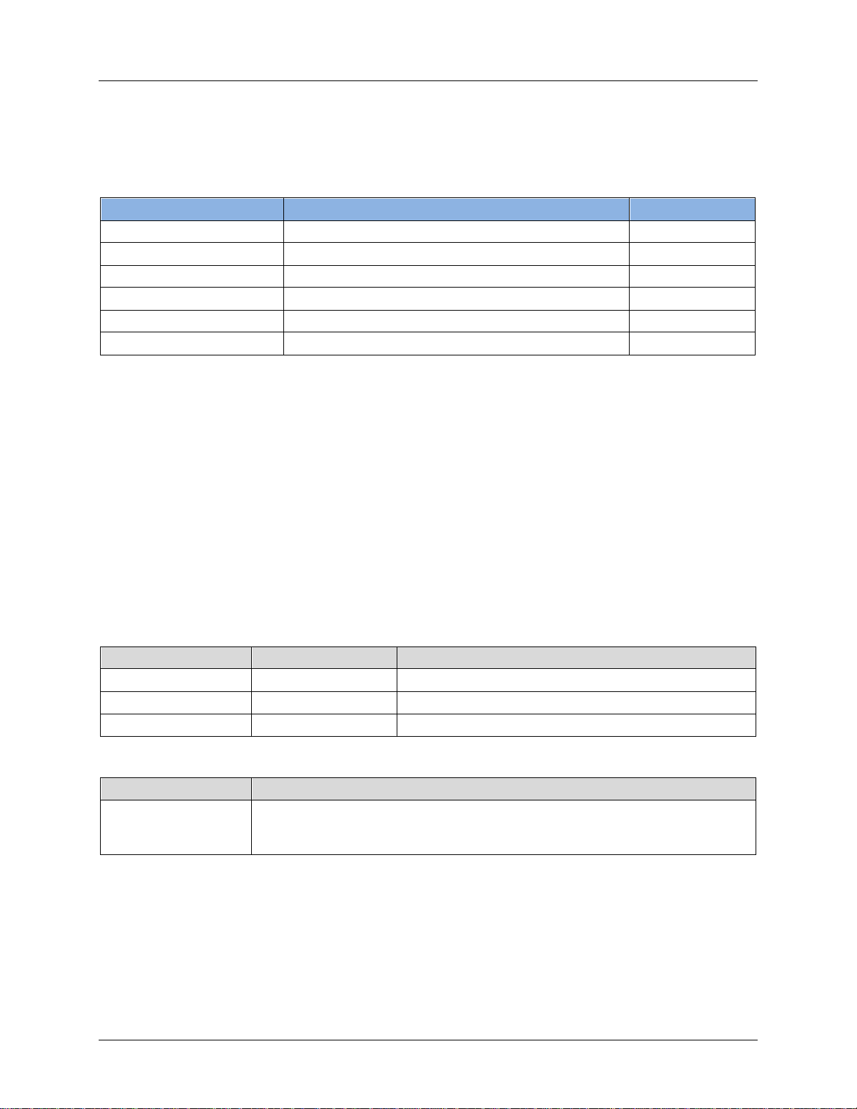
2 Overview
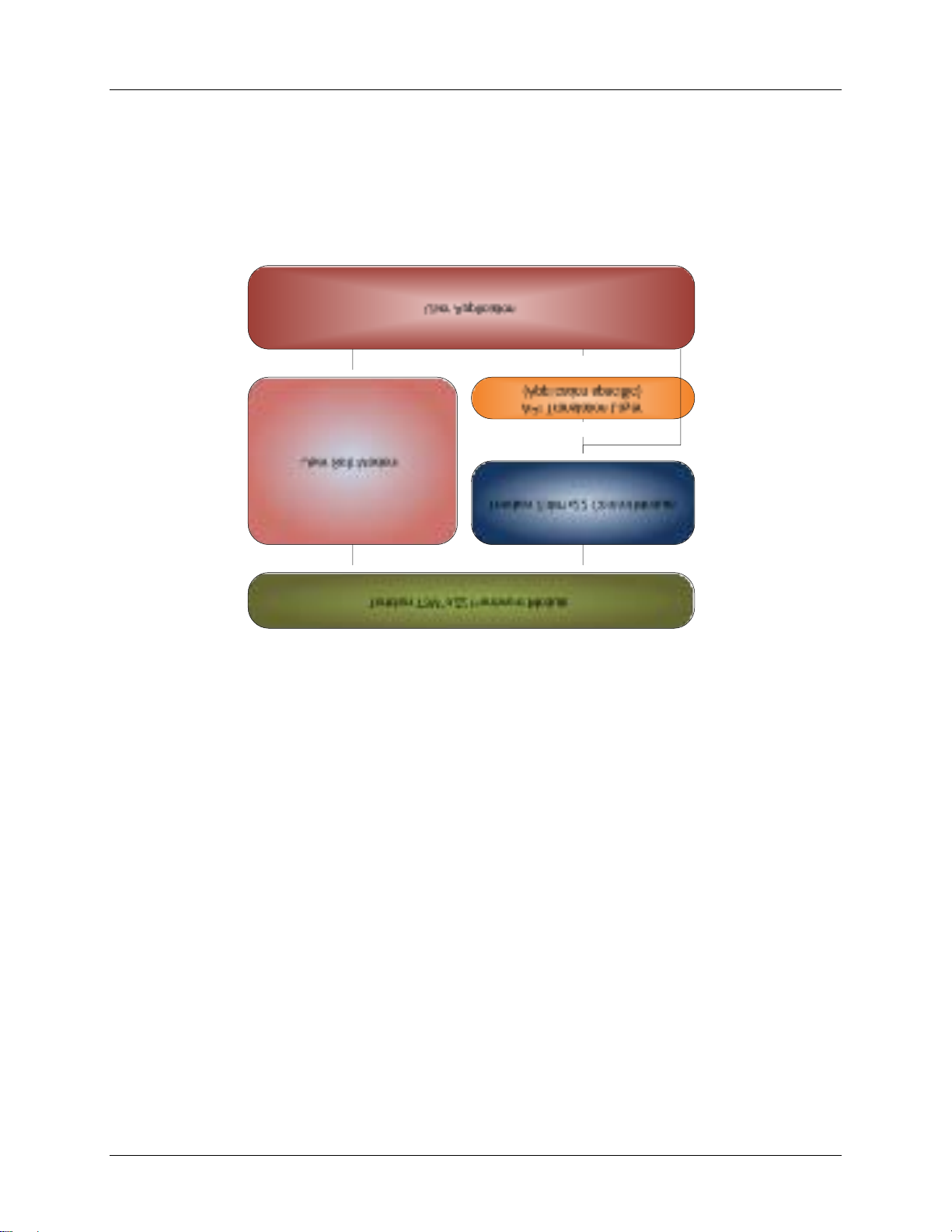
2.1 Driver Archite ctur e
The dri ver provides a framework by wh i ch applica tions can leverage th e featu r es of the chipset. The
main interface of th e driver ( IOCTLs) provides an abstract ion layer for monitori ng and control of the
device status. Figure 1 depicts the general driver architecture.
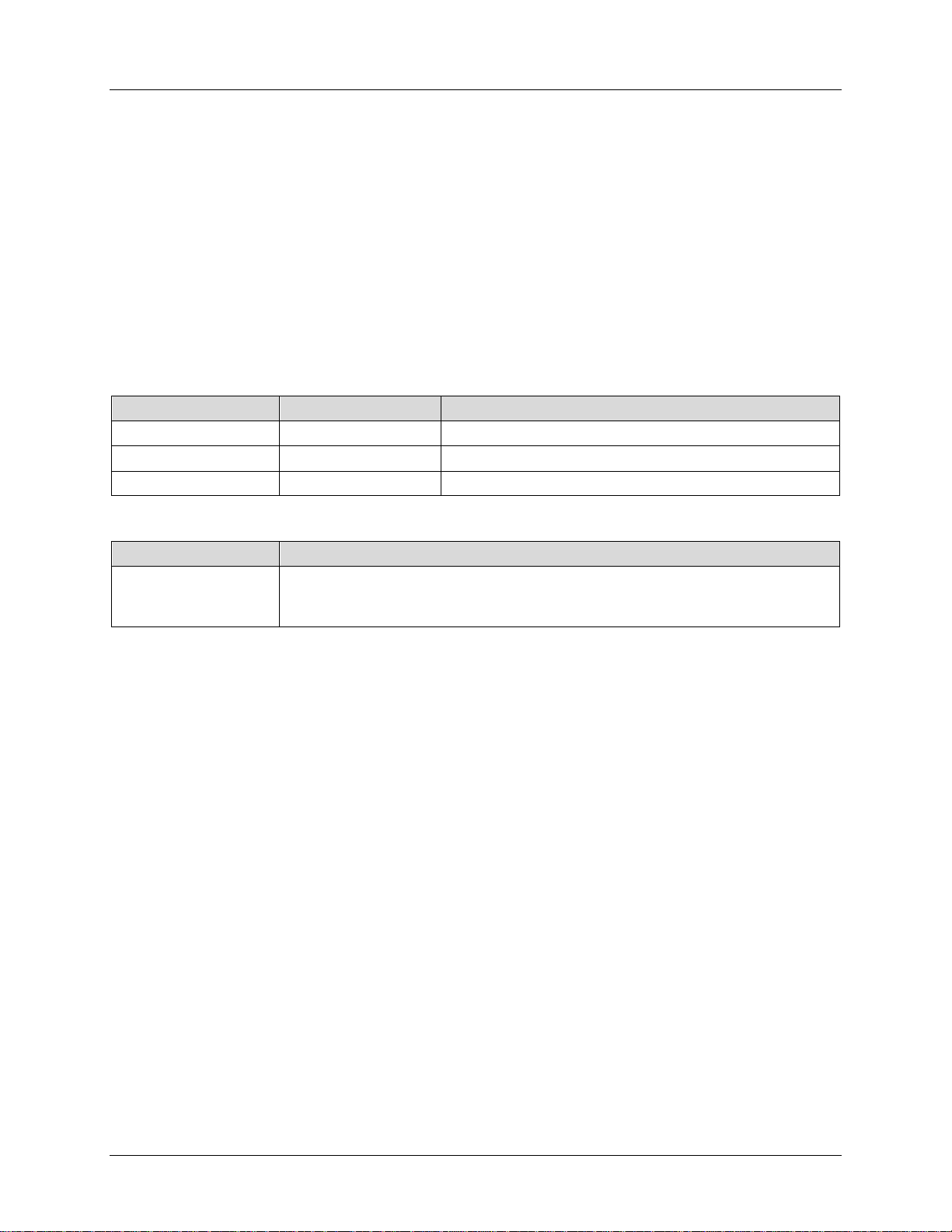
Device status is analyzed and processe d by an independently running process based on predefined
algori thms. When an event or an even sequ ence is r ecogn i zed, the driver posts the correspond ing event
to be r etrieved by the user appl i cation. Figure 2 depi cts the dr i ver functiona l block diagram.
Figure 1: General Driver Architecture
8 Rev. 1.0
Page 9

UG_1x22_053 73M1822/73M1922 Control Module User Guide
Teridian 73M1x22 Hardware Module
73M1x22 Control Module
User Application Software
IOCTLs
73M1x22 Chip Set
State Processor
Timers
MAFE ISR
Events
OS/BSP
Figure 2: Driver Functional Block Diagram
The dri ver provides an interface to user appli cation thr ough the I OCTL and Events interface. Through this
interface, the user applicat i on communica tes with the dr iver via a standard device in terface (open, close,
select, ioctl function s). Using this in terface the applicat i on will b e able to co ntrol the operat ion of the
device and t o r etrieve the status of the modem l i ne. Section 6 descri bes t he details of thi s interface.
The 73M1x22 driver is built as a Linux loadable module (for Linux) or integrated with the operating system
kernel. It will be brought into operation by a u ser applicat ion or b y an operat ing sy stem start up script.
For Linux, the insmod command i s used to insert the driver into the kernel. The insmod command
invokes the module_init() macro, which in turn runs the one-tim e initiali zation function of the d r iver.
Befor e exiting t he initializat i on the driver enters its main operational st ate via the scheduli ng of one of
many timer s that m ake up the driver’s main processing.
2.2 Functional Overv ie w
Once instal led, the driver is a sel f-contained module running independent l y along wit h the ker nel
processes. Its main purp ose is to monitor the modem line for vari ous conditions, generates appropriated
event when they occur, and to pr ovide access to the 73M1x22 d evice for managem ent purposes, via
standard driver access meth ods such as open, close, select, ioctl, etc. Th e fol l owing secti ons
provide an overview of that functionality.
Rev. 1.0 9
Page 10

73M1822/73M1922 Control Module User Guide UG_1x22_053
2.2.1 Event Generation
During operation the driver constantly monitors the line for the following conditions:
1. APO H condition.
2. Transi tion back to no APOH condit ion (NOPOH).
3. Ring start detection.
4. End of Ring co ndition.
5. Batter y disconnected conditi on.
6. Batter y restored condit i on.
7. Polarity reve r sal conditi on.
8. Line State condition – mon itoring of voltage and current.
9. Synchronization l oss condit ion.
10. Synchroni zation recovered event.
11. Over vol t a g e, Over current, or O ver load co ndition.
12. Pul se dial complete event.
13. Pul se dial aborted event.
Section 5 provides detail descripti ons of each event.
If any o f these cond i tions occu r the driver creates an event ent r y in th e event queue and not ifies the
app l ication layer via file descriptor ready mechanism (or via file descr i ptor select() function). Upon
receiving this “wakeup ” notification , th e application can then test the file descriptor “r eady” statu s with the
FD_ISSET macr o to confi r m, and th en r etrieve t he event from the driver via I OCTL event get command.
2.2.2 Modem Channel Configuration and Management
Configuration of the modem parameters and other management command such as hook swi tch operation
are done via standar d device driver IOCTLs. The 73M1x22 Reference Driver provides an extended list of
IOCTLs for this purpose. The IOCTL command descriptions in Section 6 provide details of how they
work.
2.2.3 Line State Analysis via Current and Voltage Measurements
The 73M1x22 Contr ol M odule can be programmed to provide extended line status information and line
monitoring cap ability. The driver operates autonomou sly, under the application layer control, to d etect line
condition specified in pre-set criteria and automat i cally report status change. This alleviates the burden of
constant pollin g from the applicat i on layer. The line statu s consists of the line voltage and line cu r r ent
measurem ents. Each measurement ent i ty is oper ated independen tly as described be low.
2.2.3.1 Interval and Even Table
The Interval and Event Table (IET) is a table that consists of mult iple rows of the following information:
1. Row number.
2. Lower bound threshold.
3. Upper bound threshold.
4. Appli cation defined event.
The application is r esponsible for building up the IET using the IET table update IOCTL –
M1X22_MEASURE_UPDATE. This IO CTL can be used t o create/update or to read back the curren t table
entr y (see Sect ion 6.6.3 for d etails).
10 Rev. 1.0
Page 11

UG_1x22_053 73M1822/73M1922 Control Module User Guide
2.2.3.2 Measurement Procedure
The dri ver is responsible for reading the raw value required at a given sample rate f r om the device. Th e
result is co m puted and averaged ove r a speci fied number of those previously read values, and then
compare to the interval an d event table (IET) described b el ow. Based on these comparisons dedicated
events may be sent to the application.
The dri ver com pares the calculat ed average of the reading value with the lower and upp er bound
thr eshold in each IET table entry. If the value falls in between the r anges and it is the first transition into
these new ranges the specific applica tion defined event (4) will be se nt t o the application. The lower and
upp er bound ranges ar e expressed in milliamps for curr ent intensi ty, or in volts for line voltage.
2.2.3.3 Management of the Procedure
Controllin g the operat ion of this curr ent/ voltage measur ement is exclusivel y done b y t he application layer.
The application layer uses the M1X22_MEASURE_START and M1X22_MEASURE_STOP to st ar t and stop
the m easurement , resp ectively. The sim ply stops the measurement and requires no additional
parameter, wh ile M1X22_MEASURE_START starts the measuring pr ocess and it consists of two
parameters:
1. Sample tim e i nterval.
2. Averag e sample cou nt.
The sample t ime interval is the t ime interval between tw o consecuti ve reading sam ples exp r essed in
mil l isecon ds, and the aver age sample co unt is the number of reading sa m ples to be used for aver age
calculation. An y one of these parameters can be ZERO in dicates a no ch ange. The application layer can
adjust one or both param eters an ytime using M1X22_MEASURE_START.
2.2.3.4 Even Handling
The dri ver emits the M1X22_LINE_STATE event when line state condition changes from on e inter val to
another. Th e appli cation is expected to recei ve the notification and can request for the event from the
driver using the M1X22_GET_EVENT IOCTL. Refer to Section 5 for details on how to get n otified and to
retrieve the event from the driver’s queue. The following supporting data will accompany the line state
event:
1. Th e state of th e modem chann el – on or off-hook.
2. Line current or line voltage.
3. IET row index.
4. Appli cation defined event.
2.2.4 GPIO Support
Four General Purpose I/O pins ( GPIOs) pins can be managed independentl y and used for carrying i nput
or out put signal t o and from the 73M1x22 device. If used as input, signal transition on the pin can be
detected and tri gger in terrupt to the host CP U . The dr i ver provides the ability to p r ogram each GPIO pin
as in put or output port, the abil ity to read and write dat a to th e GPIO pin as well as generating interrupt
event correspond the signal transition. Section 6.7 describes the GP IO related IOCTL.
Note: The GPIO feature exists only on cert ai n 73M1x22 device packages.
Rev. 1.0 11
Page 12

73M1822/73M1922 Control Module User Guide UG_1x22_053
2.2.5 Loopback and Testing Modes
The 1x22 devices supp or t several variations of loopback modes. R efer to th e “ Loopback and Testin g
Modes” section of th e 73M1822/ 73 M 19 22 Data Sh ee t for more det ai l. Each loopback mode is designed
to test con n ectivity at vari ous p oints in th e system. Systematically u se of the loopback featur e i n
conj uncti on with ext er nal application that contr ol data stream in and out of th e system can be an effective
tool t o i solate faul ts. While th e driver pr ovides IOCTLs to manage those loopback test poi nts, i t does not
have a way to inject or intercept d ata flow through the sy stem to perform diagnosti c. It relies on exter nal
app l ication for th ose capabilities. Th e IOCTL for managing the loopback can be found in Sectio n 6. 8.1.
2.2.6 Call Progress Monitor
The 1x22 device provides the ab ility to moni tor activity on the li ne via feature call ed the Call Progress
Monitor. The gain se tting of its audio path can be adjusted using th e M1X22_CPROG_MONITOR IOCTL
detailed in Secti o n 6.9.3. F or m or e detail on this subject, refer to the “Call P r ogress Moni tor” section of
the 73M1822/73M1922 Data Sheet.
2.2.7 Billing Tone Filter
Some countries u se a large ampl i tude out-of-band tone t o measure call duration and to allow r emote
central office s to d etermi ne the durat i on of a call for bil l ing purposes. To avoid saturation and distor tion of
the input caused by these tones, it is im portant to be able to rej ect them. These freq uencies are typically
12 kHz and 16 kHz. Refer to section “Billing Tone Rejection” i n the 73M1822/ 73 M 19 22 D ata Sheet for
more detail.
To enable or di sable the billin g tone filter, t he dri ver offers the M1X22_BTONE_FILTER IOCTL. Its
description can be found in Section 6.9.2.
12 Rev. 1.0
Page 13

UG_1x22_053 73M1822/73M1922 Control Module User Guide
3 Driver Service Interface
The Driver Ser vice p r ovides the li nk b etween the modem device and th e user application. Fir st, the driver
must be loaded and bound in to the op er ating system environment before t his se r vice can be provided .
Acce ss to the driver is done via two file descrip tors – the device and channel file descript or s. The device
file descriptor provides access to devi ce leve l management interface wh i le the chan nel descriptor is use d
to m anage at the channel level interface. The driver suppor ts multiple modem channels through
separated channel descriptor s; however, only one d evice d escrip tor is used.
The following sections describe how the driver is brought into action based on the operating system
environment.
3.1 Linux Operating System
This description is valid for Linux 2.4 and 2.6. The 73M1x22 driver takes the form of a Linux standard
character d evice d r iver. It is brought into operation by a user app lication or by Linux startup script using
the
insmod command. This command inse r ts the dri ver module in to th e kernel wh i ch in turn registers
with the kernel using the defaul t major n umber of 251. Multiple modem chann els are supported via the
use of minor number wh ich ca n varies from 0 to 16. This minor number associated with th e device an d
channel descrip tors created using m knod command. Th e driver expects the minor num ber 0 to be
associ ated with the device descriptor and t he number from 1 to 16 with the channel descriptors. Device
major and mi nor num bers are co nfigurable at build tim e as described in Section 8.2.
The device and channel descriptors ca n be creat ed in the /dev directory at the sa me tim e wh en the
driver is insmod into the kernel. The mknod command is used to create th ose descriptors as illustrated
below:
mknod -m 660 /dev/tsc_1x22_ctl_device c 251 0
mknod -m 660 /de v/tsc_1x22_ctl_ cha nne l c 251 1
In this exam ple, one device descri ptor (tsc_1x22_ctl_device) is created with major number 251,
minor number 0, and one channel descrip tor (tsc_1x22_ctl_channel) is cr eated with major number
251 , minor num ber 1. The minor number base (0 ) can b e changed ( see the compile time configurable
parameter in Section 8.2).
Once the dr iver is installed and the device/chann el descriptors are creat ed, t he dri ver service ca n be
accessed via stan dard C l ibrary
functions.
The following ill ustr ates how t he device and channel ar e opened, closed, and the IOCTL access:
devfd = open("/dev/tsc_1x22_ctl_device", O_RDONLY|O_WRONLY);
chanfd = open (“/ dev /ts c_1x22_ctl_chan nel ”, O_R DONLY|O_WRONLY) ;
ioctl (devfd, M1X22_EVENT _GET, &event_struc tur e);
ioctl (chanfd, M1X22_ATH1, NULL);
close (devfd);
close (chanfd);
Accessing the driver using IOCTL must be done via an opened descriptor. There are two types of IOCTL
commands – the device level commands, which can be accessed by an opened device descriptor, and
channel l evel command s, which can be accessed using an opened chann el descriptor. Secti on 6
describes the IOCTL commands.
3.2 Other Operating Systems
open(), and subsequently with select(), close(), and ioctl()
To be provided.
Rev. 1.0 13
Page 14

73M1822/73M1922 Control Module User Guide UG_1x22_053
4 Country Specific Settings
The 73M1x22 Control Module su pports global com pliance parameters for each DAA d evice it manag es.
When select ed for a specific co untry code using M1X22_CH_INIT, the followin g predefined parameters
will be applied:
1. AC terminati on imp edance – AC imped ance register value.
2. DC termination mask – DC mask value.
3. Ring Detection – Ring detection threshold value.
4. Automatic CID Enable – Automatically en ter CID state when on hook.
5. U se Seize Stat e – If set, the driver enter seize state for 350 ms b efore setting ENNOM (ref er to the
73M1822/73M1922 Data Sheet for a detailed explan ation of the seize state).
These p ar ameters are defin ed in the Country Code Parameter files ( tsc_1x22_ctl_cntry_tbl.c)
and can be changed as required. The list of the co untry codes support ed can b e found in Appendix A.
14 Rev. 1.0
Page 15

UG_1x22_053 73M1822/73M1922 Control Module User Guide
unsigned int
event_id
unsigned int
channel_id
unsigned int
event_cnt
unsigned int
event_data1
unsigned int
event_data2
unsigned int
event_data3
unsigned int
event_data4
5 Modem Events
The dri ver provides event service to the high level application by maintaining a FIFO queue of event
structures, M1X22_MDM_EVENT_t. Events are created by the dri ver to reflect various cond ition s as
described in Section 5.2. Once created, this new even t is added to the FIFO queue an d the driver not ifies
the application layer via file descriptor status chang e mechanism. This in tu r n trigger s the application to
request for t he even t via th e M1X22_EVENT_GET IOCTL . Upon r etrieval, each even t struct ure is removed
from t he FIFO queue after its inform ation i s conveyed to the hi gh level application.
To receive this modem even t not ification th e application must r egister for file descriptor status change
usi ng the standard UNIX select() function. When this function retu r ns the m odem event availabi lity
status will r eflect i n the file descriptor parameter. The FD_ISSET macro can be used for checking the
status, and if available, the application can request for the event using M1X22_EVENT_GET.
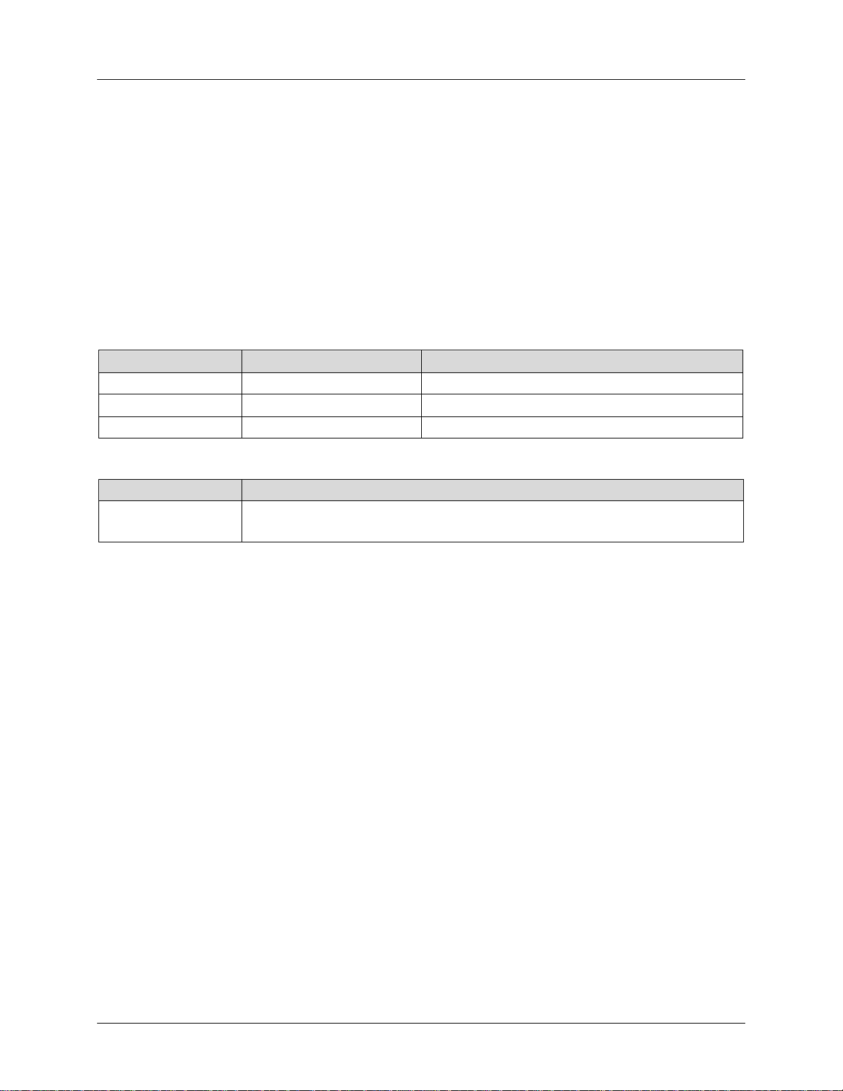
5.1 M1X22_MDM_EVENT_t
Description
Thi s str uct ur e is used by M1X22_EVENT_GET to retrieve an e vent from the event queue. The event
structure consists of event ID indentifying the event, the channel ID identifying the modem channel where
the event was generated, the number of remai ning events in th e queue, and up to four event data that
carries additional i nformation pertaining to that sp ecific event.
Prototype
typedef struct {
unsigned int event_id; /* Event ID */
unsigned int channel_id; /* Channel ID */
unsigned int event_cnt; /* number of remaining queued events */
unsigned int event_data1; /* additional data 1 */
unsigned int event_data2; /* additional data 2 */
unsigned int event_data3; /* additional data 3 */
unsigned int event_data4; /* additional data 4 */
}
M1X22_MDM_EVENT_t;
Parameters
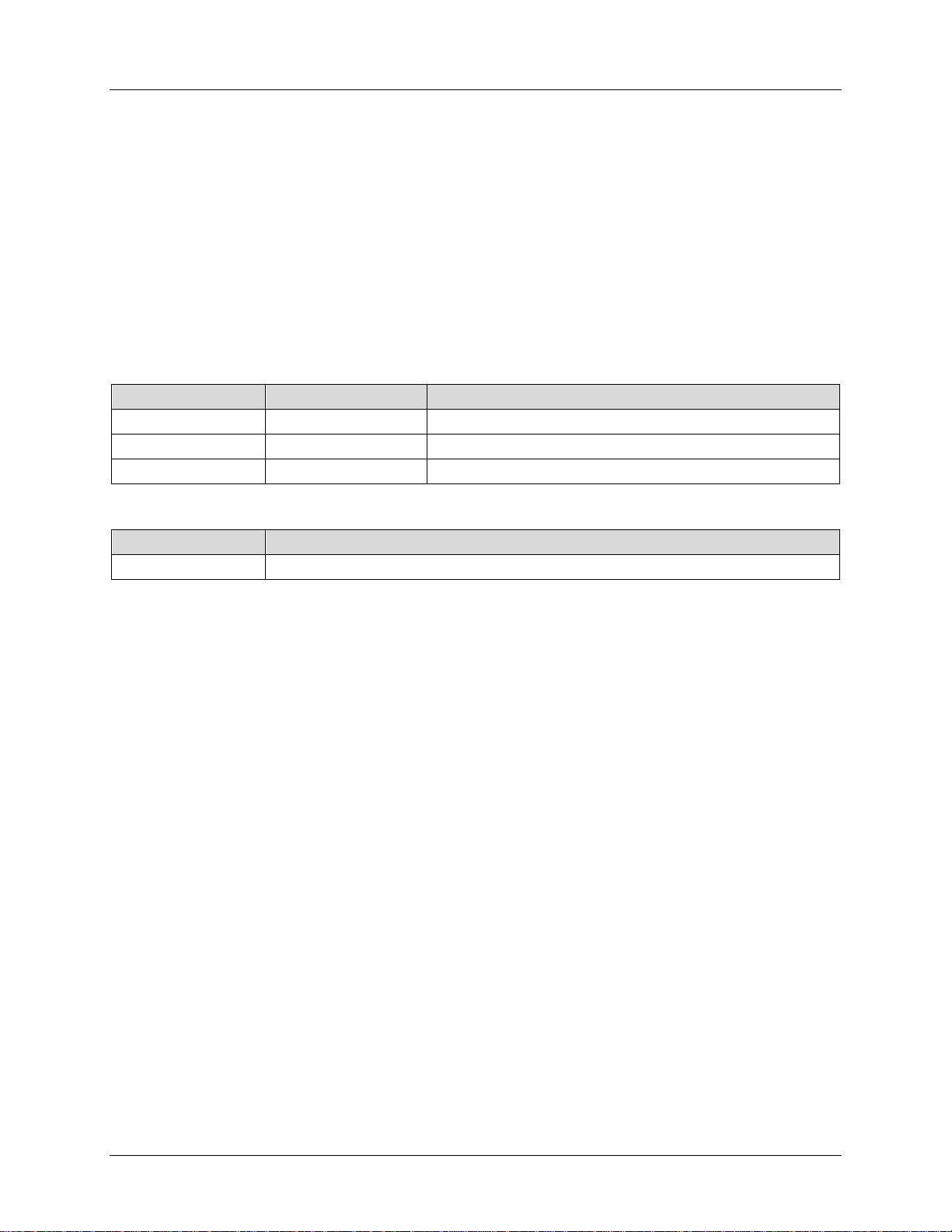
Data T ype Name Description
Event ID (see Section 5.2).
Channel ID.
Number of events that remain in the queue.
Event data 1.
Event data 2.
Event data 3.
Event data 4.
Rev. 1.0 15
Page 16

73M1822/73M1922 Control Module User Guide UG_1x22_053
M1X22_BATTERY_DROPPED
unsigned int
channel_id
unsigned int
event_cnt
unsigned int
event_data1
unsigned int
event_data2
unsigned int
event_data3
unsigned int
event_data4
unsigned int
event_id
M1X22_BATTERY_FEEDED
unsigned int
channel_id
unsigned int
event_cnt
unsigned int
event_data1
unsigned int
event_data2
unsigned int
event_data3
unsigned int
event_data4
unsigned int
event_id
M1X22_APOH_DETECT
unsigned int
channel_id
unsigned int
event_cnt
unsigned int
event_data1
unsigned int
event_data2
unsigned int
event_data3
unsigned int
event_data4
5.2 Event Identification
5.2.1 M1X22_BATTERY_DROPPED
This event occurs wh en the modem line is di sconnected from the telephone n etwork.
Parameters
Data T ype Name Description
unsigned int event_id
Channel ID.
Number of events that remain in the queue.
N/A.
N/A.
N/A.
N/A.
5.2.2 M1X22_BATTERY_FEEDED
This event is generated when the lin e is conn ected to the telephone network and the voltage is restored
to nor mal op er ating level.
Parameters
.
Data T ype Name Description
Channel ID.
Number of even ts that remain in the queue.
N/A.
N/A.
N/A.
N/A.
5.2.3 M1X22_APOH_DETECT
This event is gen er ated when a parallel phone goes off hook.
Parameters
Data Type Name Description
Channel ID.
Number of events that remain in the queue.
N/A.
N/A.
N/A.
N/A.
.
.
16 Rev. 1.0
Page 17
UG_1x22_053 73M1822/73M1922 Control Module User Guide
unsigned int
event_id
M1X22_NOPOH_DETECT
unsigned int
channel_id
unsigned int
event_cnt
unsigned int
event_data1
unsigned int
event_data2
unsigned int
event_data3
unsigned int
event_data4
unsigned int
event_id
M1X22_POLARITY_CHG
unsigned int
channel_id
unsigned int
event_cnt
unsigned int
event_data1
unsigned int
event_data2
unsigned int
event_data3
unsigned int
event_data4
unsigned int
event_id
M1X22_RING_DETECT
unsigned int
channel_id
unsigned int
event_cnt
unsigned int
event_data1
unsigned int
event_data2
unsigned int
event_data3
unsigned int
event_data4
5.2.4 M1X22_NOPOH_DETECT
This event is gen er ated when a parallel phone goes on h ook.
Parameters
Data T ype Name Description
.
Channel ID.
Number of events that remain in the queue.
N/A.
N/A.
N/A.
N/A.
5.2.5 M1X22_POLARITY_CHG
This event is gen er ated when th er e is a voltag e r eversal occurs on th e line.
Parameters
Data T ype Name Description
.
Channel ID.
Number of events that remain in the queue.
N/A.
N/A.
N/A.
N/A.
5.2.6 M1X22_RING_DETECT
This event is generated at the beginning of the ring burst.
Parameters
Data T ype Name Description
Rev. 1.0 17
.
Channel ID.
Number of events that remain in the queue.
Ring burst frequency (in Hz)
N/A.
N/A.
N/A.
Page 18

73M1822/73M1922 Control Module User Guide UG_1x22_053
unsigned int
event_id
M1X22_RING_DETECT_END
unsigned int
channel_id
unsigned int
event_cnt
unsigned int
event_data1
unsigned int
event_data2
unsigned int
event_data3
unsigned int
event_data4
unsigned int
event_id
M1X22_SYNC_LOSS_DETECT
unsigned int
channel_id
unsigned int
event_cnt
unsigned int
event_data1
unsigned int
event_data2
unsigned int
event_data3
unsigned int
event_data4
unsigned int
event_id
M1X22_OV_DETECT
unsigned int
channel_id
unsigned int
event_cnt
unsigned int
event_data1
unsigned int
event_data2
unsigned int
event_data3
unsigned int
event_data4
5.2.7 M1X22_RING_DETECT_END
This event is generated when the driver detects the end of the ring burst.
Parameters
Data T ype Name Description
.
Channel ID.
Number of events that remain in the queue.
Ring burst frequency (in Hz)
Ring bur st dura ti o n (i n ms)
N/A.
N/A.
5.2.8 M1X22_SYNC_LOSS_DETECT
This event is gen er ated when th e dr i ver detects the failur e of synchronization acr oss the barrier p ath.
Parameters
Data T ype Name Description
.
Channel ID.
Number of events that remain in the queue.
N/A.
N/A.
N/A.
N/A.
5.2.9 M1X22_OV_DETECT
This event is gen er ated on detect ion of an over voltage lin e condition.
Parameters
Data T ype Name Description
18 Rev. 1.0
.
Channel ID.
Number of events that remain in the queue.
N/A.
N/A.
N/A.
N/A.
Page 19

UG_1x22_053 73M1822/73M1922 Control Module User Guide
unsigned int
event_id
M1X22_OI_DETECT
unsigned int
channel_id
unsigned int
event_cnt
unsigned int
event_data1
unsigned int
event_data2
unsigned int
event_data3
unsigned int
event_data4
unsigned int
event_id
M1X22_LINE_STATE
unsigned int
channel_id
unsigned int
event_cnt
M1X22_OFF_HOOK
M1X22_CURRENT
unsigned int
event_data3
unsigned int
event_data4
unsigned int
event_id
M1X22_DIAL_COMPLETE.
unsigned int
channel_id
unsigned int
event_cnt
unsigned int
event_data1
unsigned int
event_data2
unsigned int
event_data3
unsigned int
event_data4
5.2.10 M1X22_OI_DETECT
This event is gen er ated on detect ion of an over curr ent li ne con diti on.
Parameters
Data T ype Name Description
.
Channel ID.
Number of events that remain in the queue.
N/A.
N/A.
N/A.
N/A.
5.2.11 M1X22_LINE_STATE
This event is gen er ated when th e line state analysis process detects a chan ge in the state of t he lin e.
The lin e state analysis process will monitor (und er user con trol) the line current and/ or voltage in both On
and off hook st ates. Th i s event indicat es that either the user has requested the current li ne state or one
of the programm able threshold states has b ecome active or non active.
Parameters
Data T ype Name Description
.
Channel ID.
Number of events that remain in the queue.
unsigned int event_data1
unsigned int event_data2
M1X22_ON_HOOK,
.
M1X22_VOLTAGE,
.
IET row number.
Event identifier.
5.2.12 M1X22_DIAL_COMPLETE
This event is gen er ated when a pulse dial se ssion i s comp l eted successfully.
Parameters
Data T ype Name Description
Channel ID.
Number of events that remain in the queue.
N/A.
N/A.
N/A.
N/A.
Rev. 1.0 19
Page 20

73M1822/73M1922 Control Module User Guide UG_1x22_053
unsigned int
event_id
M1X22_DIAL_ABORTED
unsigned int
channel_id
unsigned int
event_cnt
unsigned int
event_data1
unsigned int
event_data2
unsigned int
event_data3
unsigned int
event_data4
unsigned int
event_id
M1X22_SYNC_RECOVERED
unsigned int
channel_id
unsigned int
event_cnt
unsigned int
event_data1
unsigned int
event_data2
unsigned int
event_data3
unsigned int
event_data4
M1X22_GPIO_INTERRUPT
unsigned int
channel_cid
unsigned int
event_cnt
unsigned int
event_data1
unsigned int
event_data2
unsigned int
event_data3
unsigned int
event_data4
5.2.13 M1X22_DIAL_ABORTED
This event is gen er ated when a pulse dial se ssion i s aborted or canceled by the user appl i cation.
Parameters
Data T ype Name Description
.
Channel ID.
Number of events that remain in the queue.
N/A.
N/A.
N/A.
N/A.
5.2.14 M1X22_SYNC_RECOVERED
This event is gen er ated after a successful r ecovery from th e bar r i er sync failure.
Parameters
Data T ype Name Description
.
Channel ID.
Number of events that remain in the queue.
N/A.
N/A.
N/A.
N/A.
5.2.15 M1X22_GPIO_INTERRUPT
This event occurs when an input GPIO interrupt is triggered. The “data1” field contains the source GPIO
that generates the interrupt .
Parameters
Data T ype Name Description
unsigned int event_id
20 Rev. 1.0
.
Channel CID.
Number of events that remain in the queue.
The GPIO that triggers the interrupt event.
N/A.
N/A.
N/A.
Page 21

UG_1x22_053 73M1822/73M1922 Control Module User Guide
M1X22_CH_INIT
M1X22_CNTRY_NMBR_ GET
M1X22_PHONE_VOLUME_SET
M1X22_SET_SAMPLING_FREQ
M1X22_GET_SAMPLING_FREQ
6 IOCTL Commands Description
Upon successful opening of a device or ch annel descriptor the application layer can control the operation
of the device and the mod em chann el. The app licati on in user space commu nicates with the driver via
standard Linux dr iver interfac e IOCTL calls.
Unless sp ecified, in general, the IOCTL function r eturns zero (0) for successful requ est, or a negative
value of EFAULT (-EFAULT) if an y error is detected during the processing of th e IOCTL. The more det ail
cause of error, or also known as error code, is stored internally and can be retrieved with the
M1X22_ERROR_CODE_GET IOCTL. The driver keeps only the last er r or code of the last IOCTL per device
or channel descriptor . Therefore, if requir ed, th e er r or code must be retrieved immediately a fter th e
execution of the IOCTL or before the next IOCTL is executed. The error codes are l isted in Section 7.4.
The following section s describe th e detail of each IOCTL command. The dr i ver IOCTL belongs to one of
the fol l owing categories:
• Initialization
• Event and St atus Ser vices
• mod em H ook Switch Con trol Ser vices
• Caller-ID Services
• Ring Detection Services
• Lin e State A nalysis Servic es
• GPIO Services
• Miscell aneous Ser vice
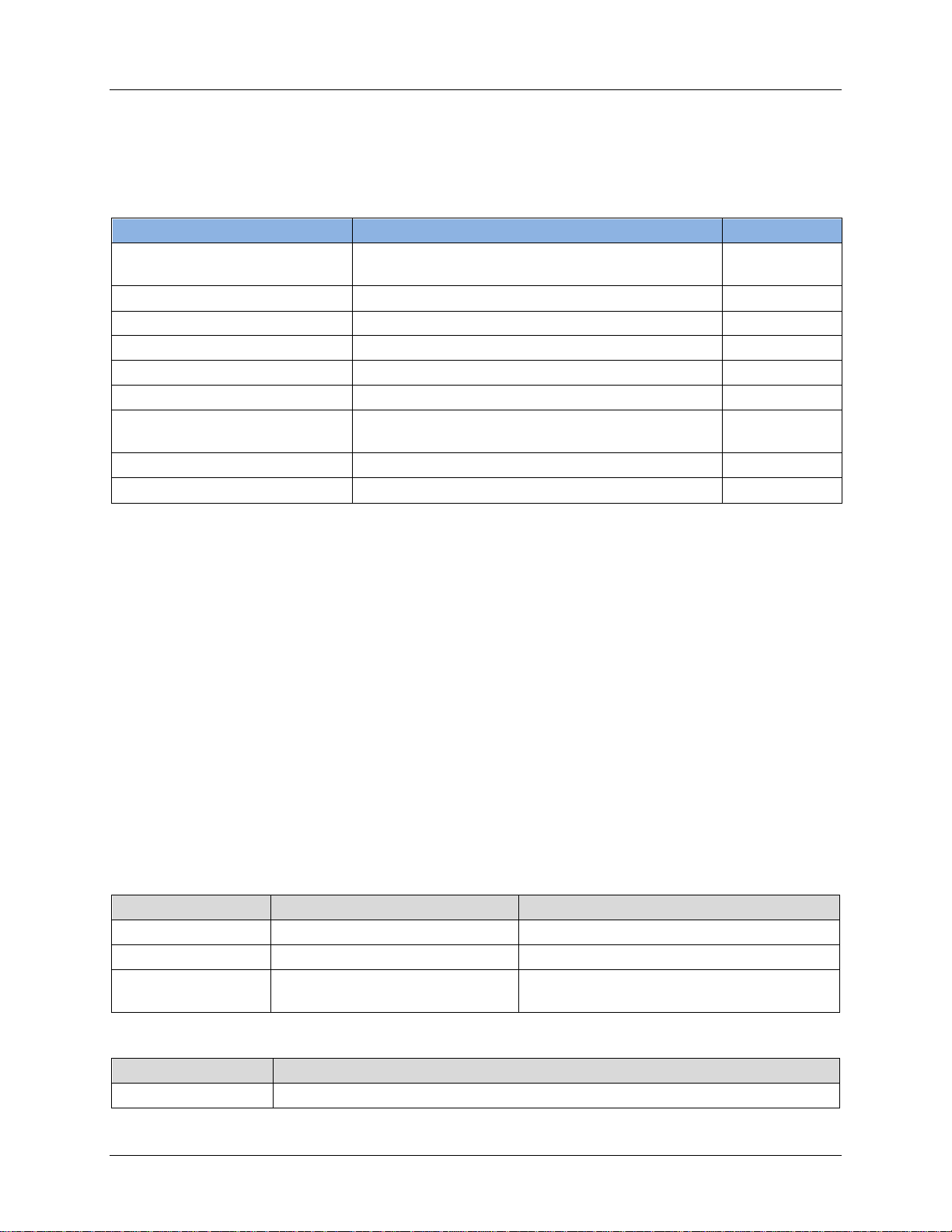
6.1 Initialization and Configuration IOCTLs
The following IOCTLs are defined to configure the 73M1x22. Table 1 provides a summar y of the IO CTLs.
Table 1: Summary of Initialization IOCTLs
IOCTL Name Description Descriptor
Initializing modem ch annel for operation. Channel
M1X22_GET_COUNTRY_CONFIG
M1X22_SET_COUNTRY_CONFIG
Convert ASCII two-character country code
into country code index used by the driver.
Read the current default setti ng for a given
country code.
Overwrites the current default setti ng for a
particular country.
Set transmit and r eceive gain. Channel
Select modem sample rate Channel
Get current mod em sample rate Channel
Channel
Channel
Channel
Rev. 1.0 21
Page 22
73M1822/73M1922 Control Module User Guide UG_1x22_053
int
chan_fd
int
M1X22_CH_INIT
unsigned long
param
M1X22_COUNTRY_CODE
6.1.1 M1X22_CH_INIT
Description
Perfo r ms 73M1x22 channel initialization. This includes init i alize all defau l t regi sters and country specific
thr eshold parameters. Th is IO C TL requires the coun try code l i sted i n M1X22_COUNTRY_CODE as input.
The modem channel will be initial ized according to the default se tting parameter of the input country
code. The default setting parameter can be fou nd in the tsc_1x22_ctl_cntry_tbl.c file. See also
M1X22_GET_COUNTRY_CONFIG and for run-tim e m odification of country default setting.
#define M1X22_CH_INIT _IOWR(0 xA4 ,0x C8, unsigned int)
Prototype
int ioctl (
int chan_fd,
int M1X22_CH_INIT,
unsigned long param );
Parameters
Data T ype Name Description
Channel descriptor.
I/O control identifier for this operation.
Country code as listed in
Return Values
.
Data T ype Description
int
-1 – Failed to initialize device.
0 – Successful.
22 Rev. 1.0
Page 23

UG_1x22_053 73M1822/73M1922 Control Module User Guide
int
chan_fd
int
M1X22_CNTRY_NMBR_GET
unsigned long
param
6.1.2 M1X22_CNTRY_NMBR_GET
Description
Conver ts a n ull ter minat ed ASCII string into a country code. Thi s country code can be used in the
M1X22_CH_INIT IOCTL.
#define M1X22_CNTRY_NMBR_GET _IOW R(0xA4,0xB5,uns ign ed int )
Prototype
int ioctl (
int chan_fd,
int M1X22_CNTRY_NMBR_GET,
unsigned long param );
Parameters
Data T ype Name Description
Channel descriptor.
I/O control identifier for this operation.
Add r ess of th e null terminated character string.
Return Values
Data T ype Description
int
Return country code – M1X22_COUNTRY_CODE.
255 – Invalid count r y code.
Rev. 1.0 23
Page 24

73M1822/73M1922 Control Module User Guide UG_1x22_053
int
chan_fd
int
M1X22_GET_COUNTRY_CONFIG
M1X22_CNTRY_STRUCT_t
6.1.3 M1X22_GET_COUNTRY_CONFIG
This IOCTL all ows an application prog r am to read the curren t default setti ng for a particular cou ntry u sing
the countr y co de as an i nput.
Description
Reads the current default sett ing for a given cou ntry. The country code is passed in via the cnum fiel d of
the M1X22_CNTRY_STRUCT_t structure. This structure is also used by the driver to return the
parameter.
#define M1X22 _GE T_C OUNTRY_CONFIG _IOWR(0xA4, 0xF 4, uns ign ed int)
Prototype
int ioctl (
int chan_fd,
int M1X22_GET_COUNTRY_CON FIG ,
unsigned long param );
Parameters
Data T ype Name Description
Channel descriptor.
I/O control identifier for this operation.
unsigned long param
Return Values
Pointer to stru cture
.
Data T ype Description
int
Example
The following example illustr ates the readi ng of t he default setting for UK.
M1X22_CNTRY_STRUCT_t country_config;
country _co nfi g.c num = M1X22_CNT RY_CODE_U K;
ioctl (fd, M1X22_GET_COUNTRY_CONFIG, (unsigned long) &country_config);
printf (“\nCountry Code : %s”, country_config.ccode);
printf (“\nac_impedance : %d”, country_config.ac_impedance);
printf (“\ndc_vi_mask : %d”, country_config.ac_vi_mask);
printf (“\nrgth_value : %d”, country_config.rgth_value);
printf (“\nauto_cid_enable : %d”, country_config.auto_cid_enable);
printf (“\nuse_seize_state : %d”, country_config.use_seize_state);
printf (“\n\n”);
0 – Successful.
-EFAULT – Fail ed to get countr y co nfig parameter.
24 Rev. 1.0
Page 25

UG_1x22_053 73M1822/73M1922 Control Module User Guide
int
chan_fd
int
M1X22_SET_COUNTRY_CONFIG
unsigned long
param
M1X22_CNTRY_STRUCT_t
int
6.1.4 M1X22_SET_COUNTRY_CONFIG
This IOCTL allows application program to write the current default setting for a particular country using
the countr y co de as an i nput. Once written t his beco mes th e new defaul t setting for the count r y code until
the sy stem i s rebooted. F or per sistence change of d efault co untry parameter the
tsc_1X22_ctl_cntry_tbl.c must be change and rebuilt.
Description
Write to the current defaul t setting of a given coun try code. The new count r y config parameter is passed
in via t he M1X22_CNTRY_STRUCT_t structure.
#define M1X22_SET_COUNTRY_CONFIG _IOWR(0xA4, 0xF5, unsigned int)
Prototype
int ioctl (
int chan_fd,
int M1X22_SET_COUNTRY_CON FIG ,
unsigned long param );
Parameters
Data T ype Name Description
Channel descriptor.
I/O control identifier for this operation.
Pointer to stru cture
Return Values
.
Data T ype Description
Always returns 0.
Example
The following example illustr ates the writing of the new countr y config setting for UK.
M1X22_CNTRY_STRUCT_t country_config;
country_config.cnum = M1X22_CNTRY_CODE_UK;
strcpy ((v oid *) &coun try _config.ccode, “UK ”);
strcpy ((void *) &country_config.country, “United Kingdom”);
country_config.ac_impedance = 3;
country_config.dc_vi_mask = 2;
country_config.rgth_value = 1;
country _co nfi g.a uto_cid_enable = FALSE;
country_config.use_seize_ state = FALSE;
ioctl (fd, M1X22_SET_COUNTRY_CONFIG, (unsigned long) &country_config);
Rev. 1.0 25
Page 26
73M1822/73M1922 Control Module User Guide UG_1x22_053
int
chan_fd
int
M1X22_PHONE_VOLUME_SET
6.1.5 M1X22_PHONE_VOLUME_SET
Description
The gain of bot h transmit and receive path can be contr olled by digital and/or anal og means. This IOCTL
provid es an easy way to set the transmi t and receive gain.
#define M1X22_PHONE_VOLUME_SET _IOW R(0xA4,0x CA, uns ign ed int)
Prototype
int ioctl (
int chan_fd,
int M1X22_PHONE_VOLUME_SET,
unsigned long param );
Parameters
Data T ype Name Description
Channel descriptor.
I/O control identifier for this operation.
unsigned long param
Return Values
Pointer to stru cture txrx_gain (see Section
7.4).
Data T ype Description
int
0 – Successful.
(-1) – Failed.
26 Rev. 1.0
Page 27

UG_1x22_053 73M1822/73M1922 Control Module User Guide
int
chan_fd
int
M1X22_SET_SAMPLING_FREQ
M1X22_SAMPLE_RATE_SELECTION
6.1.6 M1X22_SET_SAMPLING_FREQ
Description
Select modem sample rate. The 73M1x22 device can operate at many differen t sam ple rates ranging
from 7.2 kHz to 16 kHz. The device default s to 7.2 kHz operation with a 24.576 MHz crystal upon startup
and can be changed using this ioctl.
Notes: Changing of the sample rate w i ll af fect the following :
1. Barrier interface operation – a m omentari ly lost of synchronizati on on the barrier inter face is
expect ed. However, t he dri ver will automatical ly att empt to recover barri er synchron ization. The
SYNC lost event is sent and shou ld be followed by SYN C r estored event when the bar r i er is s ynced
up again.
#define M1X22_SET_SAMPLING_FREQ _IOWR(0xA4, 0xA8, unsigned int)
Prototype
int ioctl (
int chan_fd,
int M1X22_SET_SAMPLING_FREQ,
unsigned long param );
Parameters
Data T ype Name Description
Channel descriptor.
I/O control identifier for thi s operat ion.
unsigned long param
Return Values
Data T ype Description
int
0 – Successful.
-EFAULT– Failed to set sample rate.
Sample rate selection as defined in
.
Rev. 1.0 27
Page 28

73M1822/73M1922 Control Module User Guide UG_1x22_053
int
chan_fd
int
M1X22_GET_SAMPLING_FREQ
unsigned long
param
int
M1X22_SAMPLE_RATE_SELECTION
6.1.7 M1X22_GET_SAMPLING_FREQ
Description
Return curr ent modem sample rate. The 73 M 1x22 d evice can operate at many differen t sam ple rat es
ranging from 7.2 kHz to 16 kHz. The device defaul ts to 7.2 kHz operation with a 24.576 MHz crystal upon
startup.
#define M1X22_GET_SAMPLING_FREQ _IOWR(0xA4, 0xA8, unsigned int)
Prototype
int ioctl (
int chan_fd,
int M1X22_GET_SAMPLING_FREQ)
unsigned long param );
Parameters
Data T ype Name Description
Channel descriptor.
I/O control identifier for this operation.
N/A.
Return Values
Data T ype Description
Sample rate selection as defined in
.
28 Rev. 1.0
Page 29
UG_1x22_053 73M1822/73M1922 Control Module User Guide
M1X22_RNG_GET
M1X22_POL_GET
M1X22_BAT_GET
M1X22_POH_GET
M1X22_EVENT_GET
M1X22_ERROR_CODE_GET
int
chan_fd
int
M1X22_RNG_GET
unsigned long
param
int
6.2 Events and Status Service
The dri ver can be queried for a variety of cu r r ent statu s of the m odem line via IOCTLs. Table 2
summarize s these services.
Table 2: Modem Li ne Sta t us Services
Events and Status Description Descriptor
6.2.1 M1X22_RNG_GET
Description
Gets the current ring status of the modem line. The current ring status is m aintai ned in the driver internal
variable. This variable is being retrieved by use application using this command.
#define M1X22_RNG_GET _IOWR(0xA4,0xB8,unsigned int)
Prototype
Modem line r ing status com mands. Channel
Modem line polarity status commands. Channel
Modem line battery status comm and. Channel
Modem line POH status command. Channel
Event retrieval command. Device
Retrieve last error code command. Device/Channel
int ioctl (
int chan_fd,
int M1X22_RNG_GET,
unsigned long param );
Parameters
Data T ype Name Description
Channel descriptor.
I/O control identifier for this operation.
N/A.
Return Values
Data T ype Description
The return value can be either of the follo w ing:
0 – No ring signal occurred on the modem lin e.
1 – The modem line is ringing, signal ing of in coming call.
Rev. 1.0 29
Page 30

73M1822/73M1922 Control Module User Guide UG_1x22_053
int
chan_fd
int
M1X22_POL_GET
unsigned long
param
6.2.2 M1X22_POL_GET
Description
Gets the current polarity reversal status of the modem line. The dr i ver main tains this statu s in its loca l
variab le and i t is being retrieved by user application using this co m mand.
#define M1X22_POL_GET _IOWR(0xA4,0xB7,unsigned int)
Prototype
int ioctl (
int chan_fd,
int M1X22_POL_GET,
unsigned long param );
Parameters
Data T ype Name Description
Channel descriptor.
I/O control identifier for this operation.
N/A.
Return Values
Data T ype Description
int
The return value can be either of the follo w ing:
0 – No polarity reve r sal event.
1 – polarity reversal eve nt occurred on th e modem l ine.
30 Rev. 1.0
Page 31
UG_1x22_053 73M1822/73M1922 Control Module User Guide
int
chan_fd
int
M1X22_BAT_GET
unsigned long
param
6.2.3 M1X22_BAT_GET
Description
Gets the current battery statu s of the modem l ine. The d r iver maintain s this status in its l ocal variable and
it is being retrieved by user application using th i s command.
#define M1X22_BAT_GET _IOWR(0xA4,0xB6,unsigned int)
Prototype
int ioctl (
int chan_fd,
int M1X22_BAT_GET,
unsigned long param );
Parameters
Data T ype Name Description
Channel descriptor.
I/O control identifier for this operation.
N/A.
Return Values
Data T ype Description
int
The return value can be either of the follo w ing:
0 – The modem line is not powered.
1 – The modem line is connected to the PSTN and be i ng po wered.
Rev. 1.0 31
Page 32

73M1822/73M1922 Control Module User Guide UG_1x22_053
int
chan_fd
int
M1X22_POH_GET
unsigned long
param
6.2.4 M1X22_POH_GET
Description
Gets the current “parall el phone off-hook” status of the modem line. The driver maintains this status in its
local variab le and it is being retrieved by user applicat i on using this command.
#define M1X22_PO H_G ET _IOWR(0 xA4 ,0xB9,unsigned int )
Prototype
int ioctl (
int chan_fd,
int M1X22_POH_GET,
unsigned long param );
Parameters
Data T ype Name Description
Channel descriptor.
I/O control identifier for this operation.
N/A.
Return Values
Data T ype Description
int
The return value can be either of the follo w ing:
0 – No parallel phone off-h ook on the modem line.
1 – A parallel phone off-hook on the modem line.
32 Rev. 1.0
Page 33

UG_1x22_053 73M1822/73M1922 Control Module User Guide
int
dev_fd
int
M1X22_EVENT_GET
int
6.2.5 M1X22_EVENT_GET
Description
Returns an event from the FIF O queue. The driver record s various even ts in its in ternal FI FO queue.
Acce ss to this event on thi s queu e by user application is accomplished usi ng this command, and the
event will be removed permanen tly from the queue.
#define M1X22_EVENT_GET _IOWR(0xA4,0xB1,unsigned int)
Prototype
int ioctl (
int dev_fd,
int M1X22_EVENT_GET,
unsigned long param );
Parameters
Data T ype Name Description
Device descriptor .
I/O control identifier for this operation.
unsigned long param
Return Values
Pointer to stru cture M1X22_MDM_EVENT_t (see
Section 5.1).
Data T ype Description
0 – Successful.
-EFA U LT Failed to retri eve event d ata.
Rev. 1.0 33
Page 34
73M1822/73M1922 Control Module User Guide UG_1x22_053
int
dev_fd/chan_fd
int
M1X22_ERROR_CODE_GET
unsigned long
param
6.2.6 M1X22_ERROR_CODE_GET
Description
This IOCTL returns the error code o f the last IO CTL command. The driver reco r ds on ly the last erro r
code and applicable to d evice and chann el descriptor .
#define M1X22_ERROR_CODE_GET _IOWR(0xA4,0xB2,unsigned int)
Prototype
int ioctl (
int dev_fd,
int M1X22_ERROR_CODE_GET,
unsigned long param );
Parameters
Data T ype Name Description
Device or Channel descriptor.
I/O control identifier for this operation.
Pointer to the error code of type unsigned int.
Return Values
Data T ype Description
int
0 – Successful.
-EFAULT – Fail ed to retrieve th e er ror code.
34 Rev. 1.0
Page 35
UG_1x22_053 73M1822/73M1922 Control Module User Guide
M1X22_ATH1
M1X22_ATH0
M1X22_ATDP
M1X22_ATDP_CANCEL
M1X22_ATDP_PARAM
M1X22_FLSH_SET
M1X22_SEND_WETTING_PULSE
int
chan_fd
int
M1X22_ENNOM_DELAY_TIMER
int
6.3 Modem Hook Switch Control Services
The con figuration and control of the modem Hook Switch is accomplished by using the IOCTLs
summarize d in Table 3.
Table 3: Modem Hook Swi tch Control Services
Events and Status Description Descriptor
M1X22_ENNOM_DELAY_TIMER
M1X22_FLSH_CFG
6.3.1 M1X22_ENNOM_DELAY_TIMER
Allows the d eveloper to tune the EnNom respon se
Channel
timer.
Issue off-hook in the mod em interface. Channel
Issue on-hook in the modem interface. Channel
Pulse dial. Channel
Pu l se dial abort or cancel. Channel
Pu l se dial param eters. Channel
Configure of flash-hook parameter for the m odem
Channel
interface.
Perfo r m hook flashi ng on the mod em interface. Channel
Perfo r m a wetti ng pulse on the modem interface . Channel
This IOCTL all ows an application prog r am to change the ENNOM delay timer from the default value of
350 ms to any value within the valid ranges of 10 to 350 ms, inclusive
Description
Delaying of E N NOM bit set ting is requir ed for loop stab i lization during off hook operation. However, t he
duration depends largely on the quality of the hook circuit design. The driver uses the default setting of
350 m s an optimized choice for response time and audio qualit y. This IOCTL allows develop ers t o tune
this timing value to sui t their specifi c need s.
#define M1X22_ENNOM_DELAY_TIMER _IOWR(0xA4, 0xF8, unsigned int)
Prototype
int ioctl (
int chan_fd,
int M1X22_ENNOM_DELAY_TIM ER,
unsigned long param );
Parameters
Data T ype Name Description
Channel descriptor.
I/O control identifier for this operation.
unsigned long param
The desired ENNOM delay du r ation.
Range from 10 to 350 m s, incl usive.
Return Values
Data T ype Description
Rev. 1.0 35
Always returns 0.
Page 36

73M1822/73M1922 Control Module User Guide UG_1x22_053
int
chan_fd
int
M1X22_ATH1
unsigned long
param
int
6.3.2 M1X22_ATH1
Description
Issues th e off-h ook signal to the modem interface.
#define M1X22_ATH1 _IOWR(0 xA4 ,0x A2,unsigned int)
Note: The drive r provides an option to g enerate a batter y status event upon complet ion of this off-hook
procedure. This option is controlled by the following macro defined in a h eader file. By defaul t th i s macro
is disabled:
#define SEND_BAT_STATUS_OFFHOOK
It i s envisioned that the application layer wil l use this event to determine i f the call establi shment should
be p r oceeded .
Prototype
int ioctl (
int chan_fd,
int M1X22_ATH1,
unsigned long param );
Parameters
Data T ype Name Description
Channel descriptor.
I/O control identifier for this operation.
N/A.
Return Values
Data Type Description
Always returns 0.
36 Rev. 1.0
Page 37
UG_1x22_053 73M1822/73M1922 Control Module User Guide
int
chan_fd
int
M1X22_ATH0
unsigned long
param
int
6.3.3 M1X22_ATH0
Description
Issues on-hook in the modem interface.
#define M1X22_ATH0 _IOWR(0 xA4 ,0x A1,unsigned int)
Prototype
int ioctl (
int chan_fd,
int M1X22_ATH0,
unsigned long param );
Parameters
Data T ype Name Description
Channel descriptor.
I/O control identifier for this operation.
N/A.
Return Values
Data T ype Description
Always returns 0.
Rev. 1.0 37
Page 38

73M1822/73M1922 Control Module User Guide UG_1x22_053
int
chan_fd
int
M1X22_ATDP
unsigned long
param
M1X22_PULSE_DIAL_t
int
6.3.4 M1X22_ATDP
Description
Perfo r ms pulse dialing on the modem channel. As a pulse dial pr ocedu r e can t ake more than a seco nd
per digit, it is absolut ely essential that this se ssion be carried out transparently in the b ackground wit hout
locking up the caller du r ing the process. Therefore, this IOCTL is a non-blocking call and it returns
immediatel y after schedulin g the background process to start the pulse dialing. For that r eason, the
retu r n cod e does n ot reflect the status of the pu l se dial, but rat her the status of th e scheduling of the
pu l se dial session.
An acti ve dial session ca n be aborted using the M1X22_ATDP_CANCEL IOC TL. If done before its
completi on, th e driver stops the diali ng and sends t he M1X22_DIAL_ABORTED event. However, upon a
successful completion of the dialing, the driver sends an M1X22_DIAL_COMPLETE event to notify th e
app l ication layer of the status. It is r ecommended th at the ap plication monitor the pulse dial status event
(M1X22_DIAL_COMPLETE or M1X22_DIAL_ABORTED) to synchronize with the driver as to when the dial
sessi on is co mpl eted.
Note: The drive r rejects all I OCTLs wh ile t his pulse d i al sessi on is in progress, except
M1X22_ATDP_CANCEL.
#define M1X22_ATDP _IOWR(0 xA4 ,0x A3,unsigned int)
Prototype
int ioctl (
int chan_fd,
int M1X22_ATDP,
unsigned long param );
Parameters
Data T ype Name Description
Channel descriptor.
I/O control identifier for this operation.
Pointer to the
Return Values
Data T ype Description
Always returns 0.
structure.
38 Rev. 1.0
Page 39

UG_1x22_053 73M1822/73M1922 Control Module User Guide
int
chan_fd
int
M1X22_ATDP_CANCEL
unsigned long
param
int
6.3.5 M1X22_ATDP_CANCEL
Description
Ab or ts or cancels an acti ve pulse session requested previously by using the M1X22_ATDP IOCTL. The
cancellation occurs in the background and, when it is don e, the d r i ver send s an M1X22_DIAL_ABORTED
event.
#define M1X22_ATDP_CANCEL _IOWR(0xA4,0x DD,unsigned int)
Prototype
int ioctl (
int chan_fd,
int M1X22_ATDP_CANCEL,
unsigned long param );
Parameters
Data T ype Name Description
Channel descriptor.
I/O control identifier for this operation.
N/A.
Return Values
Data T ype Description
Always returns 0.
Rev. 1.0 39
Page 40

73M1822/73M1922 Control Module User Guide UG_1x22_053
int
chan_fd
int
M1X22_ATDP_PARAM
unsigned long
param
M1X22_PULSE_DIAL_PARAM_t
int
6.3.6 M1X22_ATDP_PARAM
Description
This IOCTL is used to modify or read t he following defaul t pulse dial parameters:
• On hook duration (default = 60 ms)
• Off hook duration (default = 40 ms)
• Inter-digit duration (default = 1 sec)
The command field in the M1X22_PULSE_DIAL_PARAM_t struct ure ind icates wh ether i t is a read or a
write operation. For reading the dri ver returns the parameters in the st r uctur e, while fo r writing th e driver
expect s the new pul se dial param eters to be writt en in the structur e.
#define M1X22_ATDP_PARAM _IOWR(0xA4 ,0xAD,uns ign ed int )
Prototype
int ioctl (
int chan_fd,
int M1X22_ATDP_PARAM,
unsigned long param );
Parameters
Data T ype Name Description
Channel descriptor.
I/O control identifier for this operation.
Pointer to the
Return Values
Data T ype Description
Always returns 0.
structure.
40 Rev. 1.0
Page 41

UG_1x22_053 73M1822/73M1922 Control Module User Guide
int
chan_fd
int
M1X22_FLSH_CFG
int
int
chan_fd
int
M1X22_FLSH_SET
unsigned long
param
int
6.3.7 M1X22_FLSH_CFG
Description
This is the config urati on of flash-hook timing pa r a meter for the modem interface.
#define M1X22_FLSH_CFG _IOWR(0xA4,0xBA,unsigned int)
Prototype
int ioctl (
int chan_fd,
int M1X22_FLSH_CFG,
unsigned long param );
Parameters
Data T ype Name Description
Channel descriptor.
I/O control identifier for this operation.
unsigned long param
Return Values
The desired flash duration. Range from 5 to 50 m s,
inclusive. If out of rang e i t is forced to 10 ms.
Data T ype Description
Always returns 0.
6.3.8 M1X22_FLSH_SET
Description
Perfo r ms hook flashing on the modem int er face for the durat i on set by M1X22_FLSH_CFG.
#define M1X22_FLSH_SET _IOWR(0xA4,0xBC,unsigned int)
Prototype
int ioctl (
int chan_fd,
int M1X22_FLSH_SET,
unsigned long param );
Parameters
Data T ype Name Description
Channel descriptor.
I/O control identifier for this operation.
N/A.
Return Values
Data T ype Description
Rev. 1.0 41
Always returns 0.
Page 42

73M1822/73M1922 Control Module User Guide UG_1x22_053
int
chan_fd
int
M1X22_SEND_WETTING_PULSE
6.3.9 M1X22_SEND_WETTING_PULSE
Description
Perfo r ms hook flashing on th e m odem inter face for the durat i on set by param.
#define M1X22_FLSH_SET _IOWR(0xA4,0xBC,unsigned int)
Prototype
int ioctl (
int chan_fd,
int M1X22_SEND_WETTING_PU LSE ,
unsigned long param );
Parameters
Data T ype Name Description
Channel descript or .
I/O control identifier for this operation.
unsigned long param
Return Values
Integer representin g the desired wett ing pulse
duration. Range from 1 to 1000 ms. Out of
range behavior is undefined.
Data T ype Description
int
0 – Successful.
-1 – Modem ch annel i s not off-hook.
42 Rev. 1.0
Page 43

UG_1x22_053 73M1822/73M1922 Control Module User Guide
M1X22_ENABLE_CALLER_ID
M1X22_DISABLE_CALLER_ID
M1X22_ENTER_CID_MODE
M1X22_EXIT_CID_MODE
int
chan_fd
int
M1X22_ENABLE_CALLER_ID
unsigned long
param
int
6.4 Caller-I D Services
The following service control how the modem manages Type 1 Caller-ID.
Table 4: Call ID Services
Name Description Descriptor
En able automatic Caller ID enabling mode. Channel
Disable aut omati c Caller I D enabl i ng mode. Channel
Manually ent er C aller ID mode. Channel
6.4.1 M1X22_ENABLE_CALLER_ID
Description
En ables th e automatic C aller ID processing. By default the driver will start C aller ID mode with an on
hook transition . This can be enabled by upper layer app licati on using thi s service.
#define M1X22_DISABLE_CALLER_ID _IOWR(0xA4, 0xF2, unsigned int)
Prototype
Manually exit Caller ID mode. Channel
int ioctl (
int chan_fd,
int M1X22_ENABLE_CALLER_ID,
unsigned long param );
Parameters
Data T ype Name Description
Channel descriptor.
I/O control identifier for this operation.
N/A.
Return Values
Data T ype Description
Always returns 0.
Rev. 1.0 43
Page 44

73M1822/73M1922 Control Module User Guide UG_1x22_053
int
chan_fd
int
M1X22_DISABLE_CALLER_ID
unsigned long
param
int
int
chan_fd
int
M1X22_ENTER_CID_MODE
unsigned long
param
6.4.2 M1X22_DISABLE_CALLER_ID
Description
Disables the automatic Caller ID processing. By default the dri ver will st ar t Caller I D mode with an on
hook transition. This can be disabled by upper layer application using this service.
#define M1X22_DISABLE_CALLER_ID _IOWR(0xA4, 0xF2, unsigned int)
Prototype
int ioctl (
int chan_fd,
int M1X22_DISABLE_CALLER_ID,
unsigned long param );
Parameters
Data T ype Name Description
Channel descriptor.
I/O control identifier for t his operation.
N/A.
Return Values
Data T ype Description
Always returns 0.
6.4.3 M1X22_ENTER_CID_MODE
Description
Manually ent er s Call er ID mode regar dless of the state of the automati c CID se r vice.
#define M1X22_ENTER_CID_MODE _IOWR(0xA4, 0xF2, unsigned int)
Prototype
int ioctl (
int chan_fd,
int M1X22_ENTER_CID_MODE,
unsigned long param );
Parameters
Data T ype Name Description
Channel descriptor.
I/O control identifier for this operati on.
N/A.
Return Values
Data T ype Description
int
44 Rev. 1.0
0 – Successful.
-1 – If modem channel is not on-hook.
Page 45

UG_1x22_053 73M1822/73M1922 Control Module User Guide
int
chan_fd
int
M1X22_EXIT_CID_MODE
unsigned long
param
int
6.4.4 M1X22_EXIT_CID_MODE
Description
Exits Caller ID mode.
#define M1X22_EXIT_CID_MODE _IOWR(0xA4, 0xF2, unsigned int)
Prototype
int ioctl (
int chan_fd,
int M1X22_EXIT_CID_MODE,
unsigned long param );
Parameters
Data T ype Name Description
Channel descriptor.
I/O control identifier for this operation.
N/A.
Return Values
Data T ype Description
Always returns 0.
Rev. 1.0 45
Page 46
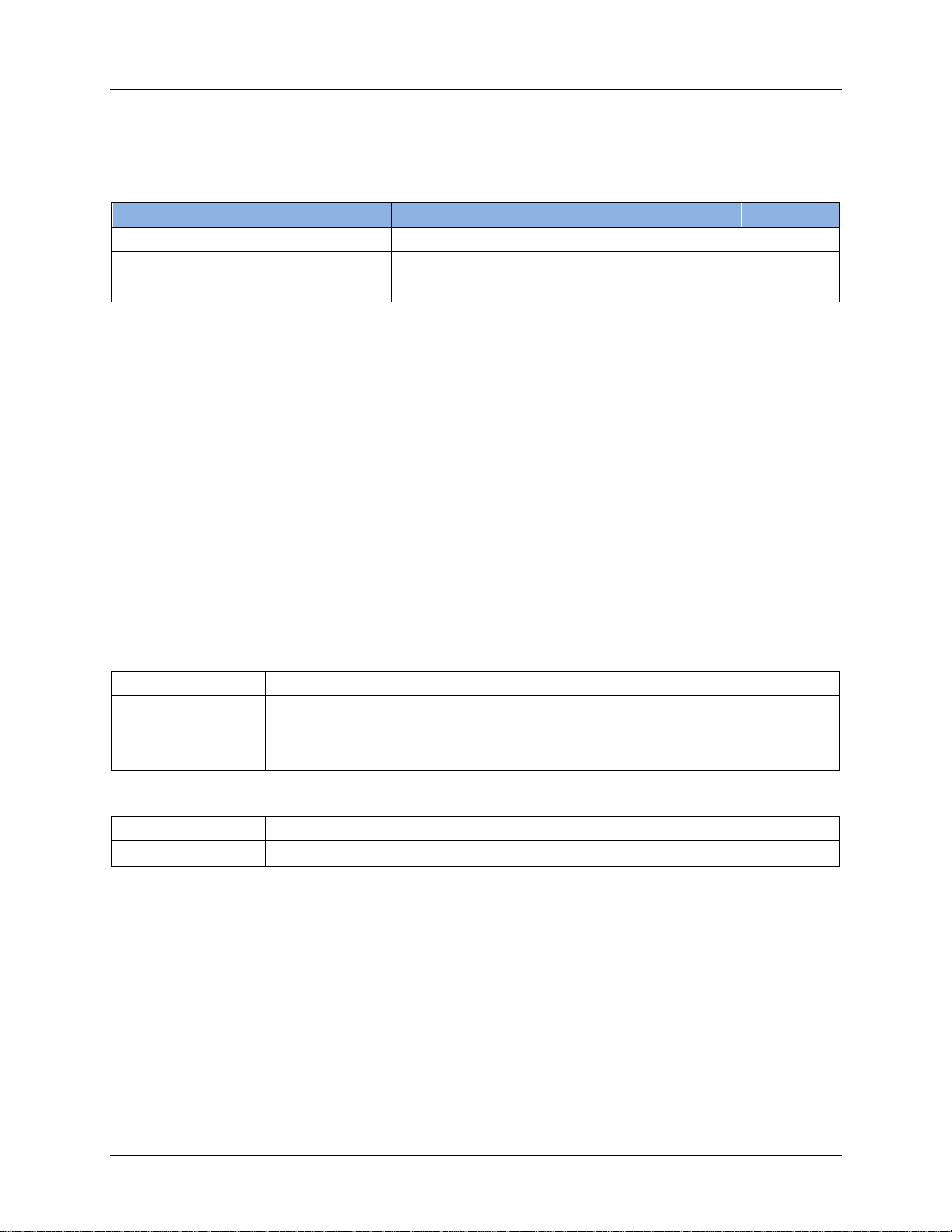
73M1822/73M1922 Control Module User Guide UG_1x22_053
M1X22_SET_MIN_INTER_RING_GAP
M1X22_SET_RING_MIN_FREQ
M1X22_SET_RING_MAX_FREQ
int
chan_fd
int
M1X22_SET_MIN_INTER_RING_GAP
unsigned long
param
int
6.5 Ring Detection Serv ic e s
The following services con trol how the modem m anages Ring Detection.
Table 5: Ring Detection Services
Name Description Descriptor
Set minimum inte r-ring timer value. Channel
6.5.1 M1X22_SET_MIN_INTER_RING_GAP
Description
Upon detection of a RGDT in terrupt the dr iver will start a tim er with a m inimum duration speci fied by this
IOCTL (default is 150 ms). If no more RGDT interrupts are detected in that time period, then the driver
will attempt to interpret the existing RGDT interrupts (polarity reversal or ring burst). Polarity reversals
and /or rin g burst s separ ated by less than this time period will be con sidered to b e one event and will be
interpret ed as such. RGDT interrupts farther apart t han this will be int er preted as separate events.
#define M1X22_SET_MIN_INTER_RING_GAP _IOWR(0xA4, 0xE2, unsigned int)
Prototype
Set min frequency threshold for ring filter. Channel
Set max frequency threshold for ring fil ter. Channel
int ioctl (
int chan_fd,
int M1X22_SET_MIN_INTER_RING_GAP,
unsigned long param );
Parameters
Data T ype Name Description
Channel descriptor.
I/O control identifier for this operation.
Time in ms.
Return Values
Data T ype Description
Always returns 0.
46 Rev. 1.0
Page 47
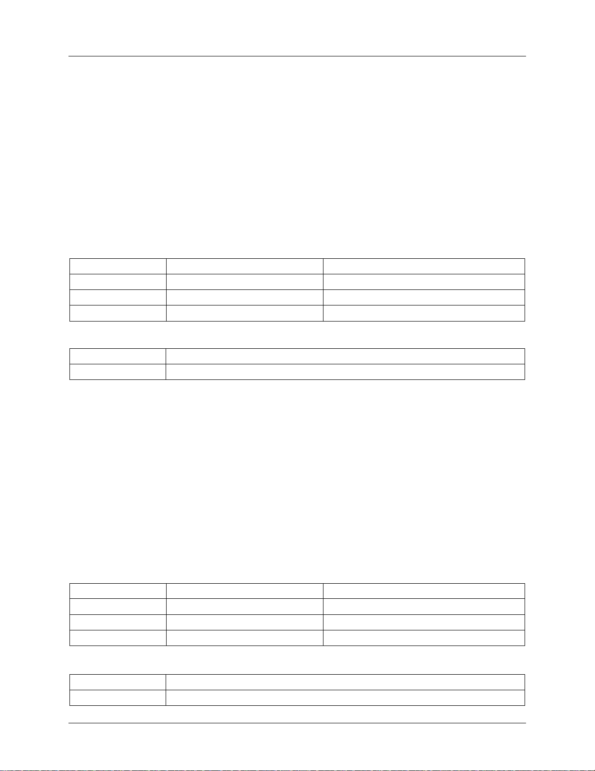
UG_1x22_053 73M1822/73M1922 Control Module User Guide
int
chan_fd
int
M1X22_SET_ RING_MIN_FREQ
unsigned long
param
int
int
chan_fd
int
M1X22_SET_ RING_MAX_FREQ
unsigned long
param
int
6.5.2 M1X22_SET_RING_MIN_FREQ
Description
Upon detection of a ring burst the driver will attempt to determine the ring burst frequency. If the ring
burst frequency is above the minimum ring frequency and below the maximum frequency then the driver
will report an M1X22_RING_DETECT event.
#define M1X22_SET_RING_MIN_FREQ _IOWR(0xA4, 0xE3, unsigned int)
Prototype
int ioctl (
int chan_fd,
int M1X22_SET_RING_MIN_FREQ,
unsigned long param );
Parameters
Data T ype Name Description
Channel descriptor.
I/O control identifier for this operation.
Frequency in Hz.
Return Values
Data T ype Description
Always returns 0.
6.5.3 M1X22_SET_RING_MAX_FREQ
Description
Upon detection of a ring burst the driver will attempt to determine the ring burst frequency. If the ring
burst frequency is above the minimum ring frequency and below the maximum frequency, then the d r iver
will report an M1X22_RING_DETECT event.
#define M1X22_SET_RING_MAX_FREQ _IOWR(0xA4, 0xE4, unsigned int)
Prototype
int ioctl (
int chan_fd,
int M1X22_SET_RING_MIN_FREQ,
unsigned long param );
Parameters
Data T ype Name Description
Channel descriptor.
I/O control identifier for this operation.
Frequency in Hz.
Return Values
Data T ype Description
Rev. 1.0 47
Always returns 0.
Page 48
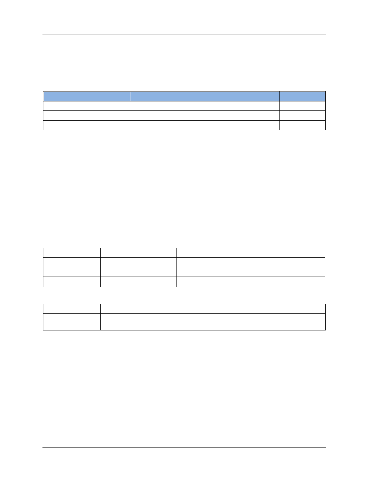
73M1822/73M1922 Control Module User Guide UG_1x22_053
M1X22_MEASURE_START
M1X22_MEASURE_STOP
M1X22_MEASURE_UPDATE
int
chan_fd
int
M1X22_MEASURE_START
M1X22_MEASURE_START_STOP_t
6.6 Line State Analysis Services
The following services con trol the modem line stat e via l ine current and line voltage measurements.
Table 6 provides the summary of each IOCTL. These IOCTLs can be u sed for both measuring entit ies –
the line current and lin e voltage.
Table 6: Line State Analysis Services
Name Description Descriptor
Start line measurement. Channel
6.6.1 M1X22_MEASURE_START
Description
Star ts the measu r ement of a measur ing entity (curren t or voltag e) as specified by its IET paramet er s. The
param parameter points to a structure th at contains the r equested measurement crit er i a.
#define M1X22_MEASURE_START _IOWR(0xA4, 0xE5, unsigned int)
Prototype
Stop line measurement. Channel
Update line measurement parameter (IET). Channel
int ioctl (
int chan_fd,
int M1X22_MEASURE_START,
unsigned long param );
Parameters
Data T ype Name Description
Channel descriptor.
I/O control identifier for this operation.
unsigned long param
Pointer to
.
Return Values
Data T ype Description
unsigned int
0 – Successful.
-1 – Failed to start measurement.
Example
The following example code illu strat es the starting of the line current monitoring.
M1X22_M EAS URE _ST ART_t current;
int ret;
current.entity = M1X22_MEASURE_ENTITY_CURRENT; /* start current monitor */
current.sample_time = 100; /* sampling at 100ms interval */
current.average_sample_count = 10; /* averaging over 10 samples */
ret = ioctl (fd, M1X22_MEASURE_START, ¤t);
if (ret < 0)
prin tf (“F ail ed to sta rt line current monitoring” );
else
prin tf (“S ucc ess ful”);
48 Rev. 1.0
Page 49

UG_1x22_053 73M1822/73M1922 Control Module User Guide
int
chan_fd
int
M1X22_MEASURE_STOP
M1X22_MEASURE_START_STOP_t
6.6.2 M1X22_MEASURE_STOP
Description
Stops an on -going measurement ( current or voltage) . The param p ar ameter points t o a stru ct ure that
contains the requested stop measuring entity.
#define M1X22_MEASURE_STOP _IOWR(0xA4, 0xE6, unsigned int)
Prototype
int ioctl (
int chan_fd,
int M1X22_MEASURE_STOP,
unsigned long param );
Parameters
Data T ype Name Description
Channel descriptor.
I/O control identifier for this operation.
unsigned long param
Return Values
Pointer to
.
Data T ype Description
unsigned long
Example
The following example code illu strat es the stoppi ng of an on-goin g voltage measurement process.
M1X22_M EAS URE _ST ART_t voltage;
int ret;
voltage.entity = M1X22_MEASURE_ENTITY_VOLTAGE; /* stop voltage monitor */
ret = ioctl (fd, M1X22_MEASURE_STOP, &voltage);
if (ret < 0)
prin tf (“F ail ed to sto p line voltage mon itoring”) ;
else
prin tf (“S ucc ess ful”);
0 – Successful.
-1 – Failed to stop measu r ement.
Rev. 1.0 49
Page 50

73M1822/73M1922 Control Module User Guide UG_1x22_053
int
chan_fd
int
M1X22_MEASURE_UPDATE
unsigned long
param
M1X22_MEASURE_UPDATE_t
6.6.3 M1X22_MEASURE_UPDATE
Description
Reads an IE T entry or updates an IET entry based on pr ovided parameters. Th e param param eter points
to a structure that cont ai ns the r equested action (G ET or SET), the m easuring ent ity (current or vol tage),
the IET table index, and its attr i butes, if use d in the SET operation. For GET operati ons the IET attributes
will be read from the driver.
#define M1X22 _ME ASU RE_UPDATE _IOWR(0xA4, 0xE 7, uns ign ed int)
Prototype
int ioctl (
int chan_fd,
int M1X22_MEASURE_UPDATE,
unsigned long param );
Parameters
Data T ype Name Description
Channel descriptor.
I/O control identifier for this operation.
Pointer to
Return Values
.
Data T ype Description
unsigned int
Example
The following example code illu strat es an u pdate t o a l ine current IET tab l e entry.
0 – Successful.
-1 – Failed to update IET entry.
M1X22_MEASURE_UPDATE_t update;
int ret;
update.row = 3; /* update row 3 of current IET table */
update.action = M1X22_MEASURE_ACTION_SET; /* req ues t for SET ope ration */
update.entity = M1X22_MEASURE_ENTITY_CURRENT; /* measuring entity= current */
update.interval_min = 15; /* lower bound current = 15ma */
update.interval_max = 21; /* upper bound current = 21ma */
update.event = 0x000E1521; /* this event to be emitted */
ret = ioctl (fd, M1X22_MEASURE_UPDATE, &update);
if (ret < 0)
prin tf (“F ail ed to upd ate current IET entry”);
else
prin tf (“S ucc ess ful”);
50 Rev. 1.0
Page 51

UG_1x22_053 73M1822/73M1922 Control Module User Guide
The following example code illu strat es a reading of a line volt age IET table entry.
M1X22_MEASURE_UPDATE_t read;
int ret;
read.row = 5; /* read row 5 of voltage IET table */
read.action = M1X22_MEASURE_ACTION_GET; /* request for GET operation */
read.entity = M1X22_MEASURE_ENTITY_VOLTAGE; /* measuring entity= voltage */
ret = ioctl (fd, M1X22_MEASURE_UPDATE, &read);
if (ret < 0)
prin tf (“F ail ed to rea d voltage IET entry”);
else {
prin tf (“\nReading vol tag e IET tab le entry row: %d”, read.row);
prin tf (“\nInterval min: %d”, read.interval_min);
prin tf (“\nInterval max: %d”, read.interval_max);
prin tf (“\nEvent : 0x%08X”, read.event);
}
Rev. 1.0 51
Page 52

73M1822/73M1922 Control Module User Guide UG_1x22_053
int
chan_fd
int
M1X22_GPIO_CONFIG
unsigned long
param
M1X22_GPIO_CONFIG_t
6.7 GPIO Services
6.7.1 M1X22_GPIO_CONFIG
Description
The ioctl is used to configure the GPIO pin.
#define M1X22 _GP IO_ CONFIG _IOWR(0xA 4, 0xC0, unsign ed int )
Prototype
int ioctl (
int chan_fd,
int M1X22_GPIO_CONFIG,
unsigned long param );
Parameters
Data T ype Name Description
Channel descriptor.
I/O control identifier for this operation.
Pointer to
Return Values
.
Data T ype Description
unsigned int
0 – Successful.
-1 – Failed to configure GPIO.
52 Rev. 1.0
Page 53

UG_1x22_053 73M1822/73M1922 Control Module User Guide
int
chan_fd
int
M1X22_GPIO_CONTROL
unsigned long
param
M1X22_GPIO_CONTROL_t
unsigned int
6.7.2 M1X22_GPIO_CONTROL
Description
The ioctl is used to control the op er ation of the GPIO pin.
#define M1X22_GPIO_CONTROL _IOWR(0xA4, 0xC1, unsigned int)
Prototype
int ioctl (
int chan_fd,
int M1X22_GPIO_CONTROL,
unsigned long param );
Parameters
Data T ype Name Description
Channel descriptor.
I/O control identifier for this operation.
Pointer to
Return Values
.
Data T ype Description
0 – Successful.
-1 – Failed to control GPIO.
Rev. 1.0 53
Page 54

73M1822/73M1922 Control Module User Guide UG_1x22_053
int
chan_fd
int
M1X22_GPIO_DATA
M1X22_GPIO_DATA_t
unsigned int
6.7.3 M1X22_GPIO_DATA
Description
This IOCTL is used to read or write data from and t o the GPIO pin.
#define M1X22_GPIO_DATA _IOWR(0xA4, 0xC2, unsigned int)
Prototype
int ioctl (
int chan_fd,
int M1X22_GPIO_DATA,
unsigned long param );
Parameters
Data T ype Name Description
Channel descriptor.
I/O control identifier for this operation.
unsigned long param
Return Values
Pointer to the
structure.
Data T ype Description
0 – Successful.
-1 – Failed to access GPIO data.
54 Rev. 1.0
Page 55

UG_1x22_053 73M1822/73M1922 Control Module User Guide
int
chan_fd
int
M1X22_LOOPBACK
M1X22_LOOPBACK_t
6.8 Loopback Services
6.8.1 M1X22_LOOPBACK
Description
This IOCTL is used for managing the loopback session – initi ating, clearing or retrieving the statu s of
curr ent active loopback se ssion on a given channel. Only one l oopback session can be active per
channel. For reading the status the loop back “mode” will be returned in the structur e
M1X22_LOOPBACK_t poi nted to by the “param” field.
#define M1X22 _LO OPB ACK _IOWR(0xA4, 0xB D, unsigned int )
Prototype
int ioctl (
int chan_fd,
int M1X22_LOOPBACK,
unsigned long param );
Parameters
Data T ype Name Description
Channel descriptor.
I/O control identifier f or this operat i on.
unsigned long param
Return Values
Pointer to stru cture
.
Data T ype Description
unsigned int
0 – Successful.
-FAULT – Fail ed to perform loopback request.
Rev. 1.0 55
Page 56

73M1822/73M1922 Control Module User Guide UG_1x22_053
int
chan_fd
int
M1X22_THRESHOLD_OVERRIDE
unsigned long
param
6.9 Miscellaneous
6.9.1 M1X22_THRESHOLD_OVERRIDE
Description
Various m odem channel parameters are convenien tly group ed and predefined in the country par ameter
setting as specified in Section 7.2. These parameters are programmed during ch annel in itialization ioctl
(M1X22_CH_INIT). However, these parameters can be overridden at r untim e to fine t une to th e desired
threshold for the specific installation using this M1X22_THRESHOLD_OVERRIDE IOCTL.
Note: This IOCTL mu st be invoked after M1X22_CH_INIT to prevent th e parameter from over writ ten by
M1X22_CH_INIT.
#define M1X22_THRESHOLD_OVERRIDE _IOWR(0xA4,0xB3,unsigned int)
Prototype
int ioctl (
int chan_fd,
int M1X22_THRESHOLD_OVERRIDE,
unsigned long param );
Parameters
Data T ype Name Description
Channel descriptor.
I/O control identifier for t his operation.
Pointer to the M1X22_THRESH_OVERRIDE_t
structure.
Return Values
Data T ype Description
int
-EFAULT – Fail ed to perform threshol d override.
0 – Successful.
56 Rev. 1.0
Page 57

UG_1x22_053 73M1822/73M1922 Control Module User Guide
int
chan_fd
int
M1X22_BTINE_FILTER
unsigned long
param
6.9.2 M1X22_BTONE_FILTER
Description
Large amplitude out-of-band tones can be used to measur e call duration and to allow remote central
office to deter min e the duration of the call for billing purposes. These tones can saturate or distor t th e
input signal, thus, it is importan t to be ab le to reject th em . This IOCTL provides the ability to filter out the
billing tone.
#define M1X22_BTONE_FILTER _IOWR(0xA4,0xC3,unsigned int)
Prototype
int ioctl (
int chan_fd,
int M1X22_BTONE_FILTER,
unsigned long param );
Parameters
Data T ype Name Description
Channel descriptor.
I/O control identifier for this operation.
Pointer to the M1X22_BTONE_FILTER_t
structure.
Return Values
Data T ype Description
int
-EFAULT – Fail ed to perform bil ling tone filter.
0 – Successful.
Rev. 1.0 57
Page 58

73M1822/73M1922 Control Module User Guide UG_1x22_053
int
chan_fd
int
M1X22_CPROG_MONITOR
unsigned long
param
6.9.3 M1X22_CPROG_MONITOR
Description
The Call Progress Monitor moni tors activities on the line. The audio output contains both t r ansmit and
receive data with a co nfigurable level individually can be set using this IOCTL.
#define M1X22_CPROG_MONITOR _IOWR(0xA4,0xF0,unsigned int)
Prototype
int ioctl (
int chan_fd,
int M1X22_CPROG_MONITOR,
unsigned long param );
Parameters
Data T ype Name Description
Channel descriptor.
I/O control identifier for this operation.
Pointer to the M1X22_CPROG_MONITOR_t
structure.
Return Values
Data T ype Description
int
-EFAULT – Failed to perform call progress monitor.
0 – Successful.
58 Rev. 1.0
Page 59

UG_1x22_053 73M1822/73M1922 Control Module User Guide
int
dev_fd
int
M1X22_DEBUG_LEVEL_SET
unsigned long
param
M1X22_DEBUG_TRACE_MASK
6.9.4 M1X22_DEBUG_LEVEL_SET
Description
Sets the dr i ver trac e mask to enable or disable run-time trace messages. Mu l tiple trace masks can be
ORed together.
#define M1X22_DEBUG_LEVEL_SET _IOWR(0xA4,0x E1, uns igned int)
Prototype
int ioctl (
int dev_fd,
int M1X22_DEBUG_LEVEL_SET,
unsigned long param );
Parameters
Data T ype Name Description
Device descriptor .
I/O control identifier for this operation.
Debug trace mask:
.
Return Values
Data T ype Description
int
-1 – Failed set debug level mask.
0 – Successful.
Rev. 1.0 59
Page 60

73M1822/73M1922 Control Module User Guide UG_1x22_053
7 Type and Structure Definition Reference
This section contains the type defini tions, reference of data type and struct ure used in th e 73M1x22
driver.
7.1 M1X22_COUNTRY_CODE
Description
List of country codes use in the M1X22_CH_INIT IOCTL.
Prototype
/*******************************************************************
** 73M1X22 Country code List - In ter net Country Cod es
*******************************************************************/
#define M1X22_CNTRY_CODE_AR 0 /* "Argentina" */
#define M1X22_CNTRY_CODE_AU 1 /* "Australia" */
#define M1X22_CNTRY_CODE_AT 2 /* "Austria" */
#define M1X22_CNTRY_CODE_BH 3 /* "Bahrain" */
#define M1X22_CNTRY_CODE_BE 4 /* "Belgium" */
#define M1X22_CNTRY_CODE_BR 5 /* "Brazil" */
#define M1X22_CNTRY_CODE_BG 6 /* "Bulgaria" */
#define M1X22_CNTRY_CODE_CA 7 /* "Canada" */
#define M1X22_CNTRY_CODE_CL 8 /* "Chile" */
#define M1X22_CNTRY_CODE_C1 9 /* "ChinaData" */
#define M1X22_CNTRY_CODE_C2 10 /* "ChinaVoice" */
#define M1X22_CNTRY_CODE_CO 11 /* "Columbia" */
#define M1X22_CNTRY_CODE_HR 12 /* "Croatia" */
#define M1X22_CNTRY_CODE_TB 13 /* "TBR 21" */
#define M1X22_CNTRY_CODE_CY 14 /* "Cyprus" */
#define M1X22_CNTRY_CODE_CZ 15 /* "Czech Rep" */
#define M1X22_CNTRY_CODE_DK 16 /* "Denmark" */
#define M1X22_CNTRY_CODE_EC 17 /* "Ecuador" */
#define M1X22_CNTRY_CODE_EG 18 /* "Egypt" */
#define M1X22_CNTRY_CODE_SV 19 /* "El Salvador" */
#define M1X22_CNTRY_CODE_FI 20 /* "Finland" */
#define M1X22_CNTRY_CODE_FR 21 /* "France" */
#define M1X22_CNTRY_CODE_DE 22 /* "Germany" */
#define M1X22_CNTRY_CODE_GR 23 /* "Greece" */
#define M1X22_CNTRY_CODE_GU 24 /* "Guam" */
#define M1X22_CNTRY_CODE_HK 25 /* "Hong Kong" */
#define M1X22_CNTRY_CODE_HU 26 /* "Hungary" */
#define M1X22_CNTRY_CODE_IS 27 /* "Iceland" */
#define M1X22_CNTRY_CODE_IN 28 /* "India" */
#define M1X22_CNTRY_CODE_ID 29 /* "Indonesia" */
#define M1X22_CNTRY_CODE_IE 30 /* "Ireland" */
#define M1X22_CNTRY_CODE_IL 31 /* "Israel" */
#define M1X22_CNTRY_CODE_IT 32 /* "Italy" */
#define M1X22_CNTRY_CODE_JP 33 /* "Japan" */
#define M1X22_CNTRY_CODE_JO 34 /* "Jordan" */
#define M1X22_CNTRY_CODE_KZ 35 /* "Kazakhstan" */
#define M1X22_CNTRY_CODE_KW 36 /* "Kuwait" */
#define M1X22_CNTRY_CODE_LV 37 /* "Latvia" */
#define M1X22_CNTRY_CODE_LB 38 /* "Lebanon" */
#define M1X22_CNTRY_CODE_LU 39 /* "Luxembourg" */
#define M1X22_CNTRY_CODE_MO 40 /* "Macao" */
#define M1X22_CNTRY_CODE_MY 41 /* "Malaysia" */
#define M1X22_CNTRY_CODE_MT 42 /* "Malta" */
#define M1X22_CNTRY_CODE_MX 43 /* "Mexico" */
60 Rev. 1.0
Page 61

UG_1x22_053 73M1822/73M1922 Control Module User Guide
#define M1X22_CNTRY_CODE_MA 44 /* "Morocco" */
#define M1X22_CNTRY_CODE_NL 45 /* "Netherlands" */
#define M1X22_CNTRY_CODE_NZ 46 /* "New Zealand" */
#define M1X22_CNTRY_CODE_NG 47 /* "Nigeria" */
#define M1X22_CNTRY_CODE_NO 48 /* "Norway" */
#define M1X22_CNTRY_CODE_OM 49 /* "Oman" */
#define M1X22_CNTRY_CODE_PK 50 /* "Pakistan" */
#define M1X22_CNTRY_CODE_PR 51 /* "Peru" */
#define M1X22_CNTRY_CODE_PH 52 /* "Philippines" */
#define M1X22_CNTRY_CODE_PL 53 /* "Poland" */
#define M1X22_CNTRY_CODE_PT 54 /* "Portugal" */
#define M1X22_CNTRY_CODE_RO 55 /* "Romania" */
#define M1X22_CNTRY_CODE_RU 56 /* "Russia" */
#define M1X22_CNTRY_CODE_SA 57 /* "Saudi Arabia" */
#define M1X22_CNTRY_CODE_SG 58 /* "Singapore" */
#define M1X22_CNTRY_CODE_SK 59 /* "Slovakia" */
#define M1X22_CNTRY_CODE_SI 60 /* "Slovenia" */
#define M1X22_CNTRY_CODE_ZA 61 /* "S. Africa" */
#define M1X22_CNTRY_CODE_KR 62 /* "S. Korea" */
#define M1X22_CNTRY_CODE_ES 63 /* "Spain" */
#define M1X22_CNTRY_CODE_SE 64 /* "Sweden" */
#define M1X22_CNTRY_CODE_CH 65 /* "Switzerland" */
#define M1X22_CNTRY_CODE_SY 66 /* "Syria" */
#define M1X22_CNTRY_CODE_TW 67 /* "Taiwan" */
#define M1X22_CNTRY_CODE_TH 68 /* "Thailand" */
#define M1X22_CNTRY_CODE_AE 69 /* "UAE" */
#define M1X22_CNTRY_CODE_UK 70 /* "UK" */
#define M1X22_CNTRY_CODE_US 71 /* "USA" */
#define M1X22_CNTRY_CODE_YE 72 /* "Yemen" */
Rev. 1.0 61
Page 62

73M1822/73M1922 Control Module User Guide UG_1x22_053
unsigned int
cnum
M1X22_COUNTRY_CODE
unsigned char
ccode[4]
unsigned char
country[16]
unsigned int
ac_impedance
unsigned int
dc_vi_mask
unsigned int
rgth_value
int
auto_cid_enable
int
use_seize_mode
7.2 M1X22_CNTRY_STRUCT_t
Description
This structur e defines the cou ntry default parameters.
Prototype
typedef struct m1X22_cntry_struct
{
unsigned int cnum; /* Country code */
unsigned char ccode[4]; /* Two letter internet country code */
unsigned char country[16]; /* Country Name */
unsigned int ac_impedance;
unsigned int dc_vi_mask;
unsigned int rgth_value;
int auto_cid_enable; /* automatically enable CID */
int use_seize_state; /* ring tone, silent duration */
} M1X22_CNTRY_STRUCT_t;
Parameters
Data T ype Name Transmit
Country code (see
Two let ter cou ntry code.
Country name.
AC impedance.
DC VI mask.
Ring voltage threshold.
Au tomatic CID en able.
Seize mode enable.
).
62 Rev. 1.0
Page 63

UG_1x22_053 73M1822/73M1922 Control Module User Guide
7.3 M1X22_DEBUG_TRACE_MASK
Description
Trace macros used by the
Prototype
#define M1X22_DEBUG_TRACE 0x00000001
#define M1X22_DEBUG_ERROR 0x80000002
#define M1X22_DEBUG_INIT 0x00000004
#define M1X22_DEBUG_EVENT 0x00000008
#define M1X22_DEBUG_IOCTL 0x00000010
#define M1X22_DEBUG_BARRIER 0x00000020
#define M1X22_DEBUG_INT 0x00000040
#define M1X22_DEBUG_KPROC 0x00000080
#define M1X22_DE BUG _COUNTRY_ COD E 0x0000 010 0
#define M1X22_DEBUG_RING_PATH 0x00000200
#define M1X22_DE BUG _LINE_STA TE 0x00000400
#define M1X22_DEBUG_PHU 0x00000800
#define M1X22_DEBUG_LOOPBACK 0x00001000
#define M1X22_DEBUG_GPIO 0x00002000
#define M1X22_DEBUG_MAFE 0x00004000
#define M1X22_DEBUG_DIAL 0x00008000
M1X22_DEBUG_LEVEL_SET IOCTL.
7.4 M1X22_LAST_ERROR_CODE
Description
The last error co de can be retr ieved by this IOC TL. This i s the list of the driver’s last error code.
Prototype
/*******************************************************************
** 73M1X22 Driver Last Error Code
*******************************************************************/
#define M1X22_ERR_OK 0x00000000 /* NO Error */
#define M1X22_ERR_INVALID_GPIO_NUM 0x00000001 /* Invalid GPIO number */
#define M1X22_ERR_INVALID_CNTRY_CODE 0x00000002 /* Invalid country code */
#define M1X22_ERR_INVALID_PARAM 0x00000003 /* Invalid parameter */
#define M1X22_ERR_INVALID_STATE 0x00000004 /* Invalid state for the command */
#define M1X22_ERR_INVALID_IOCTL 0x00000005 /* Invalid ioctl */
#define M1X22_ERR_INVALID_FD 0x00000005 /* Invalid File Descriptor */
#define M1X22_ERR_COPY_TO_USER 0x00000020 /* memcopy to user failed */
#define M1X22_ERR_COPY_FROM_USER 0x00000021 /* memcopy from user failed */
#define M1X22_ERR_PLL_NOT_LOCKED 0x00000022 /* PLL not locked */
#define M1X22_ERR_BARRIER_NOT_SYNC 0x00000023 /* Barrier not synced */
#define M1X22_ERR_NO_EVENT_DATA 0x00000024 /* No event data available */
Rev. 1.0 63
Page 64

73M1822/73M1922 Control Module User Guide UG_1x22_053
int
tx_gain
Int
rx_gain
unsigned int
length
Unsigned char
digits
7.5 struct txrx_gain
Description
This structure is used by the M1X22_PHONE_VOLUME_SET IOCTL to ad just th e volume setting of the
spea kerphone and microphone.
Prototype
struct txr x_g ain {
int tx_gain;
int rx_gain;
};
Parameters
Data T ype Name Transmit
Transmit level in dBm .
Receive level i n dB.
7.6 M1X22_PULSE_DIAL_t
Description
This structure is used by the M1X22_ATDP IOCTLs for pulse dialing.
Prototype
typedef struct m1X22_pulse_dial_struct {
unsigned int length; /* digit length */
unsigned char digits[MAX_PHONE_NMBR_DIGIT_CNT]; /* pulse dial digits */
}
M1X22_PULSE_DIAL_t;
Parameters
Data T ype Name Description
Digit leng th .
Pulse dial digits.
64 Rev. 1.0
Page 65

UG_1x22_053 73M1822/73M1922 Control Module User Guide
unsigned int
command
unsigned int
onhook_duration
unsigned int
offhook_duration
unsigned int
intra_digit_duration
unsigned char
acz
unsigned char
dciv
unsigned char
rgth
7.7 M1X22_PULSE_DIAL_PARAM_t
Description
This structure is used by the M1X22_ATDP_PARAM IOCTLs to read or modify th e pulse dial param eter.
The command field in dicates whether it i s a read or a write operation.
Prototype
typedef struct m1X22_pulse_dial_param_struct {
unsigned int command; /* pulse dial param command */
unsigned int onhook_duration; /* oh-hook duration */
unsigned int offhook_duration; /* off-hook duration */
unsigned int inter_digit_duration; /* inter-digit duration */
}
M1X22_PULSE_DIAL_PARAM_t;
Parameters
Data T ype Name Description
Pu l se dial param command:
0 – Read.
1 – Write.
On-hook duration.
Off-hook duration.
Intra-digit duration.
7.8 M1X22_THRESH_OVERRIDE_t
Description
Various m odem channel parameters are convenien tly group ed and predefined in the country parameter
setting as speci fied in section x. These param eters are programmed during chan nel initialization IOCTL
(M1X22_CH_INIT). However, these parameters can be overridden at r untim e to fine t une to th e desired
threshold for the specific installation using this IOCTL.
Prototype
typedef struct
{
unsigned char acz; /* Active Termination Loop */
unsigned char dciv; /* DC current voltage charac. control */
unsigned char rgth; /* Ring threshold
}
M1X22_THRESH_OVERRIDE_t;
Parameters
Data T ype Name Description
Active terminat i on loop.
DC current voltage characterist ic con trol.
Ring threshold.
Rev. 1.0 65
Page 66

73M1822/73M1922 Control Module User Guide UG_1x22_053
M1X22_XTAL_27000KHZ_FS_14400HZ
5
M1X22_XTAL_24576KHZ_FS_07200HZ
7
M1X22_XTAL_24576KHZ_FS_09600HZ
9
7.9 M1X22_SAMPLE_RATE_SELECTION
Description
This is the enumer ated sam ple rate selecti on. I t is used by the M1X22_SET_SAMPLING_FREQ IOCTL to
select the PCM sample rate.
Prototype
typedef enum
{
M1X22_XTAL_27000KHZ_FS_07200HZ = 1, /* Xtal = 27.000 Mhz FS = 7.2KHz */
M1X22_XTAL_27000KHZ_FS_08000HZ = 2, /* Xtal = 27.000 Mhz FS = 8.0KHz */
M1X22_XTAL_27000KHZ_FS_09600HZ = 3, /* Xtal = 27.000 Mhz FS = 9.6KHz */
M1X22_XTAL_27000KHZ_FS_12000HZ = 4, /* Xtal = 27.000 Mhz FS = 12.0KHz */
M1X22_XTAL_27000KHZ_FS_14400HZ = 5, /* Xtal = 27.000 Mhz FS = 14.4KHz */
M1X22_XTAL_27000KHZ_FS_16000HZ = 6, /* Xtal = 27.000 Mhz FS = 16.0KHz */
M1X22_XTAL_24576KHZ_FS_07200HZ = 7, /* Xtal = 24.576 Mhz FS = 7.2KHz */
M1X22_XTAL_24576KHZ_FS_08000HZ = 8, /* Xtal = 24.576 Mhz FS = 8.0KHz */
M1X22_XTAL_24576KHZ_FS_09600HZ = 9, /* Xtal = 24.576 Mhz FS = 9.6KHz */
M1X22_XTAL_24576KHZ_FS_12000HZ = 10, /* Xtal = 24.576 Mhz FS = 12.0KHz */
M1X22_XTAL_24576KHZ_FS_14400HZ = 11, /* Xtal = 24.576 Mhz FS = 14.4KHz */
M1X22_XTAL_24576KHZ_FS_16000HZ = 12, /* Xtal = 24.576 Mhz FS = 16.0KHz */
M1X22_XTAL_09216KHZ_FS_07200HZ = 13, /* Xtal = 9.216 Mhz FS = 7.2KHz */
M1X22_XTAL_09216KHZ_FS_08000HZ = 14, /* Xtal = 9.216 Mhz FS = 8.0KHz */
M1X22_XTAL_09216KHZ_FS_09600HZ = 15, /* Xtal = 9.216 Mhz FS = 9.6KHz */
M1X22_XTAL_09216KHZ_FS_12000HZ = 16, /* Xtal = 9.216 Mhz FS = 12.0KHz */
M1X22_XTAL_09216KHZ_FS_14400HZ = 17, /* Xtal = 9.216 Mhz FS = 14.4KHz */
M1X22_XTAL_09216KHZ_FS_16000HZ = 18, /* Xtal = 9.216 Mhz FS = 16.0KHz */
}
M1X22_MAFE_FREQUENCY;
Parameters
Name Value Description
M1X22_XTAL_27000KHZ_FS_07200HZ 1
M1X22_XTAL_27000KHZ_FS_08000HZ 2
M1X22_XTAL_27000KHZ_FS_09600HZ 3
M1X22_XTAL_27000KHZ_FS_12000HZ 4
M1X22_XTAL_27000KHZ_FS_16000HZ 6
M1X22_XTAL_24576KHZ_FS_08000HZ 8
M1X22_XTAL_24576KHZ_FS_12000HZ 10
Set sample rate at 27.0 MHz assum i ng a crystal
frequency of 7.2 kHz.
Set sample rate at 2 7.0 MHz assuming a crystal
frequency of 8.0 kHz.
Set sample rate at 2 7.0 MHz assuming a crystal
frequency of 9.6 kHz.
Set sample rate at 2 7.0 MHz assuming a crystal
frequency of 12.0 kHz.
Set sample rate at 2 7.0 MHz assuming a crystal
frequency of 14.4 kHz.
Set sample rate at 2 7.0 MHz assuming a crystal
frequency of 16.0 kHz.
Set sample rate at 2 4.576 MHz assuming a crystal
frequency of 7.2 kHz.
Set sample rate at 2 4.576 MHz assuming a crystal
frequency of 8.0 kHz.
Set sample r ate at 2 4.576 MHz assuming a crystal
frequency of 9.6 kHz.
Set sample rate at 2 4.576 MHz assuming a crystal
frequency of 12.0 kHz.
66 Rev. 1.0
Page 67

UG_1x22_053 73M1822/73M1922 Control Module User Guide
M1X22_XTAL_24576KHZ_FS_14400HZ
11
M1X22_XTAL_09216KHZ_FS_07200HZ
13
Name Value Description
Set sample rate at 2 4.576 MHz assuming a crystal
frequency of 14.4 kHz.
M1X22_XTAL_24576KHZ_FS_16000HZ 12
M1X22_XTAL_09216KHZ_FS_08000HZ 14
M1X22_XTAL_09216KHZ_FS_09600HZ 15
M1X22_XTAL_09216KHZ_FS_12000HZ 16
M1X22_XTAL_09216KHZ_FS_14400HZ 17
M1X22_XTAL_09216KHZ_FS_16000HZ 18
Set sample rate at 2 4.576 MHz assuming a crystal
frequency of 16.0 kHz.
Set sample rate at 9 .216 MHz assuming a crystal
frequency of 7.2 kHz.
Set sample rate at 9.216 MHz assuming a crystal
frequency of 8.0 kHz.
Set sample rate at 9.216 MHz assuming a crystal
frequency of 9.6 kHz.
Set sample rate at 9.216 MHz assuming a crystal
frequency of 12.0 kHz.
Set sample rate at 9.216 MHz assuming a crystal
frequency of 14.4 kHz.
Set sample rate at 9.216 MHz assuming a crystal
frequency of 16.0 kHz.
Rev. 1.0 67
Page 68

73M1822/73M1922 Control Module User Guide UG_1x22_053
M1X22_BTONE_FILTER_DISABLE
0
M1X22_BTONE_FILTER_ENABLE
1
M1X22_BTONE FREQ_12KHZ
0
M1X22_BTONE FREQ_16KHZ
1
7.10 Billing Tone Filter Related Data Type and Structure
7.10.1 M1X22_BTONE_FILTER_COMMAND
Description
This is the billing tone filter co mm ands. For the enable comm and the tone frequency parameter is
expect ed in the Call Prog r ess Monitor Dat a Type and Structure
.
Prototype
typedef enum
{
M1X22_BTONE_FILTER_DISABLE = 0, /* Disable billing tone filter */
M1X22_BTONE_FILTER_ENABLE = 1 /* Enable billing tone filter */
}
M1X22_BTONE_FILTER_COMMAND;
Parameters
Name Value Description
Disable billing tone filter.
Enable billing tone filter.
7.10.2 M1X22_BTONE_FREQUENCY
Description
This is the l ist of tone frequenci es th at can be filtered out. The user m ust select the right frequency to
eff e ct ively filt er out the bi l li ng t o ne .
Prototype
typedef enum
{
M1X22_BTONE_FREQ_12KHZ = 0, /* 12KHz (F1) */
M1X22_BTONE_FREQ_16KHZ = 1 /* 16KHz (F2) */
}
M1X22_BTONE_FREQUENCY;
Parameters
Name Value Description
12 kHz billing tone.
16 kHz billing tone.
68 Rev. 1.0
Page 69

UG_1x22_053 73M1822/73M1922 Control Module User Guide
unsigned char
acz
unsigned char
dciv
unsigned char
rgth
7.10.3 M1X22_BTONE_FILTER_t
Description
This structure is used by the M1X22_BTONE_FILTER IOCTL to enable or to disa ble the billing tone. The
filter is by default disable upon initialization and can be enabled to rej ect a tone of specific frequency
using this IOCTL.
Prototype
typedef struct m1X22_btone_filter
{
M1X22_BTONE_FILTER_COMMAND command; /* command */
M1X22_BTONE_FREQUENCY frequency; /* billing tone frequency */
}
M1X22_BTONE_FILTER_t;
Parameters
Data T ype Name Description
Active terminat i on loop.
DC current voltage characterist ic con trol.
Ring threshold.
Rev. 1.0 69
Page 70

73M1822/73M1922 Control Module User Guide UG_1x22_053
M1X22_CPROG_MON_VOLT_REG_1_5
0
M1X22_CPROG_MON_VOLT_REF_VCC_DIV
1
M1X22_CPROG_MON_GAIN_0DB
M1X22_C PRO G_M ON_ GAIN_MINUS_6DB
1
M1X22_CPROG_MON_GAIN_MINUS_12DB
2
M1X22_CPROG_MON_GAIN_MUTE
3
7.11 Call Progress Monitor Data Type and Structure
7.11.1 M1X22_CPROG_MON_VOLT_REF
Description
This co ntains the list of supported voltage reference at the call p r ogress monitor audio output. This is
used in the M1X22_CPROG_MONITOR IOC TL to select the voltage r eference.
Prototype
typedef enum
{
M1X22_CPROG_MON_VOLT_REG_1_5 = 0, /* 1.5 Vdc */
M1X22_CPROG_MON_VOLT_REF_VCC_DIV_2 = 1 /* VCC/2 Vdc */
}
M1X22_CPROG_MON_VOLT_REF;
Parameters
Name Value Description
1.5 Vdc reference selection.
VCC/2 Vdc reference selecti on.
7.11.2 M1X22_CPROG_MON_GAIN
Description
This contains the list of supported gain settings of the au dio path. It is use d by the
M1X22_CPROG_MONITOR IOCTL to set transmit and receive gain of th e call pr ogress monitor auto path.
Prototype
typedef enum
{
M1X22_CPROG_MON_GAIN_0DB = 0, /* Gain setting of 0dB */
M1X22_CPROG_MON_GAIN_MINUS_6DB = 1, /* Gain setting of -6dB */
M1X22_CPROG_MON_GAIN_MINUS_12DB = 2, /* Gain setting of -12dB */
M1X22_CPROG_MON_GAIN_MUTE = 3 /* Mute */
}
M1X22_CPROG_MON_GAIN;
Parameters
Name Value Description
0 Gain setting of 0 dB.
Gain sett i ng of -6dB.
Gain sett i ng of -12dB.
Mute.
70 Rev. 1.0
Page 71

UG_1x22_053 73M1822/73M1922 Control Module User Guide
M1X22_CPROG_MON_VOLT_REF
voltage_ref
M1X22_CPROG_MON_GAIN
tx_gain
M1X22_CPROG_MON_GAIN
rx_gain
7.11.3 M1X22_CPROG_MONITOR_t
Description
This structure is used by the M1X22_CPROG_MONITOR IOCTL to adjust ( or m ute) the gain setting of the
call progress monitor audio path.
Prototype
typedef struct {
M1X22_CPROG_MON_VOLT_REF voltage_ref; /* Voltage reference */
M1X22_CPROG_MON_GAIN tx_gain; /* Tx path gain setting */
M1X22_CPROG_MON_GAIN rx_gain; /* Rx path gain setting */
}
M1X22_CPROG_MONITOR_t;
Parameters
Data Type Name Description
Volt age reference.
Tra nsmi t gain.
Receive gain.
Rev. 1.0 71
Page 72

73M1822/73M1922 Control Module User Guide UG_1x22_053
M1X22_GPIO_NUM_4
0x10
M1X22_GPIO_NUM_5
0x20
M1X22_GPIO_NUM_6
0x40
M1X22_GPIO_NUM_7
0x80
M1X22_GPIO_CONFIG_GET
0
M1X22_GPIO_CONFIG_SET
1
7.12 GPIO Related Data Type and Structures
7.12.1 M1X22_GPIO_NUMBER
Description
This is the list of GPIO pi n de f i ni ti o ns.
Prototype
typedef enum
{
M1X22_GPIO_NUM_4 = 0x10, /* GPIO-4 */
M1X22_GPIO_NUM_5 = 0x20, /* GPIO-5 */
M1X22_GPIO_NUM_6 = 0x40, /* GPIO-6 */
M1X22_GPIO_NUM_7 = 0x80 /* GPIO-7 */
}
M1X22_GPIO_NUMBER;
Parameters
Name Value Description
GPIO4.
GPIO5.
GPIO6.
GPIO7.
7.12.2 M1X22_GPIO_CONFIG_COMMAND
Description
This is the GPIO configuration command. The GPIO can be configured using the
M1X22_GPIO_CONFIG_SET command. Its co nfiguration ca n be read using M1X22_GPIO_CONFIG_GET
command. The GPIO must be enabled using the M1X22_GPIO_CONTROL IOCTL for the n ew
configuration to take ef fect.
Prototype
typedef enum
{
M1X22_GPIO_CONFIG_GET = 0, /* GPIO config GET */
M1X22_GPIO_CONFIG_SET = 1 /* GPIO config SET */
}
M1X22_GPIO_CONFIG_COMMAND;
Parameters
Name Value Description
Read the GPIO configuration.
Write th e GPIO configu r ation.
72 Rev. 1.0
Page 73

UG_1x22_053 73M1822/73M1922 Control Module User Guide
M1X22_GPIO_CONTROL_DISABLE
0
M1X22_GPIO_CONTROL_ENABLE
1
M1X22_GPIO_DATA_GET
0
M1X22_GPIO_DATA_SET
1
7.12.3 M1X22_GPIO_CONTROL_TYPE
Description
GPIO control typ e definitios.
Prototype
typedef enum
{
M1X22_GPIO_CONTROL_DISABLE = 0, /* disable GPIO */
M1X22_GPIO_CONTROL_ENABLE = 1 /* enable GPIO */
}
M1X22_GPIO_CONTROL_TYPE;
Parameters
Name Value Description
Disable GPIO.
Enabl e GPIO.
7.12.4 M1X22_GPIO_DATA_COMMAND
Description
GPIO data access command. If the M1X22_GPIO_SIGNAL_DIRECTION is set to
M1X22_GPIO_DIR_INPUT, perform the M1X22_GPIO_DATA_GET returns the log i cal value of type
M1X22_GPIO_DATA_TYPE of the appropriate G PIO as an input. If the
M1X22_GPIO_SIGNAL_DIRECTION is set to M1X22_GPIO_DIR_OUTPUT, the corresponding GPIO por t
outputs the logi cal value as writt en.
Prototype
typedef enum
{
M1X22_GPIO_DATA_GET = 0, /* Read GPIO data */
M1X22_GPIO_DATA_SET = 1 /* Write GPIO data */
}
M1X22_GPIO_DATA_COMMAND;
Parameters
Name Value Description
Read GPIO data.
Write GPIO da ta .
Rev. 1.0 73
Page 74

73M1822/73M1922 Control Module User Guide UG_1x22_053
M1X22_GPIO_DATA_LOW
0
M1X22_GPIO_DATA_HIGH
1
M1X22_GPIO_DIR_INPUT
0
M1X22_GPIO_DIR_OUTPUT
1
7.12.5 M1X22_GPIO_DATA_TYPE
Description
GPIO data types – this is the GPIO data returned from the M1X22_GPIO_DATA_GET access command,
or dat a to be writ ten t o the G PIO port using the M1X22_GPIO_DATA_SET access command.
Prototype
typedef enum
{
M1X22_GPIO_DATA_LOW = 0, /* GPIO data - low */
M1X22_GPIO_DATA_HIGH = 1 /* GPIO data - high */
}
M1X22_GPIO_DATA_TYPE;
Parameters
Name Value Description
GPIO data – low.
GPIO data – high.
7.12.6 M1X22_GPIO_SIGNAL_DIRECTION
Description
GPIO pin signal direction. Th is contr ol bit i s used to design ate th e GPIO pin as either input or out put.
Prototype
typedef enum {
M1X22_GPIO_DIR_INPUT = 0, /* GPIO pin signal direction – INPUT */
M1X22_GPIO_DIR_OUTPUT = 1 /* GPIO pin signal direction - OUTPUT */
}
M1X22_GPIO_SIGNAL_DIRECTION;
Parameters
Name Value Description
GPIO pin signal direction – INPUT.
GPIO pin signal direction – OUTPUT.
74 Rev. 1.0
Page 75

UG_1x22_053 73M1822/73M1922 Control Module User Guide
M1X22_GPIO_POL_RISING
0
M1X22_GPIO_POL_FALLING
1
M1X22_GPIO_CONFIG_COMMAND
command
M1X22_GPIO_NUMBER
gpio
M1X22_GPIO_DIRECTION
direction
M1X22_GPIO_INTR_POLARITY
polarity
7.12.7 M1X22_GPIO_INTR_POLARITY
Description
GPIO Interr upt signal t r ansit ion edg e selecti on. The defines the interrupt source as bei ng either on a
rising or a falling edge of the corresponding GPIO pin. If configured as M1X22_GPIO_POL_RISING a
rising edge will trigger an interrupt from the corresponding GPIO pin. If configured as
M1X22_GPIO_POL_FALLING a falling edge will trigger an interrupt from the corresponding GPIO pin.
Prototype
typedef enum {
M1X22_GPIO_POL_RISING = 0, /* Sig transition edge polarity - RISING */
M1X22_GPIO_POL_FALLING = 1 /* Sig transition edge polarity - FALLING */
}
M1X22_GPIO_INTR_POLARITY;
Parameters
Name Value Description
Interrupt edge selection – RISING.
Interrupt edge sel ection – FALLING.
7.12.8 M1X22_GPIO_CONFIG_t
Description
This structure is used by the M1X22_GPIO_CONFIG IOCTLs to r ead or write GPIO configuration. The
first field in the con fig stru cture is the command action field – GET or SET. For the GET com mand the
“direction” and “ polarity” fields are r eturned if successful.
Prototype
typedef struct gpio_config
{
M1X22_GP IO_ CONFIG_CO MMA ND com man d; /* command */
M1X22_GPIO_NUMBER gpio; /* GPIO number */
M1X22_GPIO_SIGNAL_DIR direction; /* signal direction */
M1X22_GPIO_INTR_POLARITY polarity; /* intr edge selection */
}
M1X22_GPIO_CONFIG_t;
Parameters
Data T ype Name Description
GET or SET GPIO config command.
GPIO number.
GPIO pi n di r e ct i o n – input/output.
Interrupt on signal t r ansit ion edg e pol ar i ty.
Rev. 1.0 75
Page 76

73M1822/73M1922 Control Module User Guide UG_1x22_053
M1X22_GPIO_DATA_COMMAND
command
M1X22_GPIO_NUMBER
gpio
M1X22_GPIO_DATA_TYPE
data
M1X22_GPIO_CONTROL_TYPE
control
M1X22_GPIO_NUMBER
gpio
7.12.9 M1X22_GPIO_DATA_t
Description
This struct ur e is used by the M1X22_GPIO_DATA IOC TLs to read or write GPIO signal from or to the
GPIO pin.
Prototype
typedef struct gpio_data
{
M1X22_GPIO_DATA_COMMAND command; /* command */
M1X22_GPIO_NUMBER gpio; /* GPIO number */
M1X22_GPIO_DATA_TYPE data; /* data */
}
M1X22_GPIO_DATA_t;
Parameters
Data T ype Name Description
Read or Wri te command.
GPIO number.
Signal level to be wri tten to th e GPIO pin .
7.12.10 M1X22_GPIO_CONTROL_t
Description
This structure is used by the M1X22_GPIO_CONTROL IOCTLs to enab l e or disable the operation of the
GPIO.
Prototype
typedef struct gpio_control
{
M1X22_GPIO_CONTROL_TYPE control; /* control - enable/disable */
M1X22_GPIO_NUMBER gpio; /* gpio */
}
M1X22_GPIO_CONTROL_t;
Parameters
Data T ype Name Description
Control – enable/ disable GPI O.
GPIO number.
76 Rev. 1.0
Page 77

UG_1x22_053 73M1822/73M1922 Control Module User Guide
M1X22_LOOPBACK_CMD_GET
0
M1X22_LOOPBACK_CMD_SET
1
M1X22_LOOPBACK_CMD_CLEAR
2
M1X22_LOOPBACK_MODE_NONE
0
M1X22_LOOPBACK MODE DIGLB1
1
M1X22_LOOPBACK MODE INTLB1
2
M1X22_LOOPBACK MODE DIGLB2
3
M1X22_LOOPBACK MODE INTLB2
4
M1X22_LOOPBACK MODE ALB
5
7.13 Loopback Related Data Type and Structure
7.13.1 M1X22_LOOPBACK_COMMAND
Description
These loopb ack commands can be used in the M1X22_LOOPBACK IOCTL to manage loopback sessions.
Prototype
typedef enum
{
M1X22_LOOPBACK_CMD_GET = 0, /* Get the current loopback session */
M1X22_LOOPBACK_CMD_SET = 1, /* Set (initiate) a loopback session */
M1X22_LOOPBACK_CMD_CLEAR = 2 /* Clear (terminate) a loopback session */
}
M1X22_LOOPBACK_COMMAND;
Parameters
Name Value Description
Get the type of curr ent loopback sessi on.
Initiate a l oopback session.
Term i nate a loopback session.
7.13.2 M1X22_LOOPBACK_MODE
Description
The dri ver supports five loopback modes. Refer to the 73M1822/73M1922 Data Sheet or those loopback
reference points.
Prototype
typedef enum
{
M1X22_LOOPBACK_MODE_NONE = 0, /* No loopback */
M1X22_LOOPBACK_MODE_DIGLB1 = 1, /* Digital Loopback-1 */
M1X22_LOOPBACK_MODE_INTLB1 = 2, /* Internal Loopback-1 */
M1X22_LOOPBACK_MODE_DIGLB2 = 3, /* Digital Loopback-2 */
M1X22_LOOPBACK_MODE_INTLB2 = 4, /* Internal Loopback-2 */
M1X22_LOOPBACK_MODE_ALB = 5 /* Analog Loopback */
}
M1X22_LOOPBACK_MODE;
Parameters
Name Value Description
No Loopback.
Digi tal Loopback-1.
Internal Loopback-1.
Digi tal Loopback-2.
Internal Loopback-2.
An al og Loopback.
Rev. 1.0 77
Page 78

73M1822/73M1922 Control Module User Guide UG_1x22_053
M1X22_LOOPBACK_COMMAND
Command
M1X22_LOOPBACK_MODE
type
7.13.3 M1X22_LOOPBACK_t
Description
This is the structure used for managing the loopback with the M1X22_LOOPBACK IOCTL.
Prototype
typedef struct m1X22_loopback_struct
{
M1X22_LO OPB ACK_COMMA ND com man d;
M1X22_LOOPBACK_MODE mode;
}
M1X22_LOOPBACK_t;
Parameters
Name Value Description
Loop back command.
Loopback mode.
78 Rev. 1.0
Page 79

UG_1x22_053 73M1822/73M1922 Control Module User Guide
M1X22_MEASURE_ENTITY_CURRENT
0
M1X22_MEASURE_ENTITY_VOLTAGE
1
M1X22_MEASURE_ACTION_GET
0
M1X22_MEASURE_ACTION_SET
1
M1X22_MEASURE_ACTION_CLEAR
2
7.14 Line Measurement Related Data Types and Structures
7.14.1 M1X22_MEASURE_ENTITY
Description
This is the enumerated list of li ne measuring ent ities that can be monitored by the driver.
Prototype
typedef enum
{
M1X22_MEASURE_ENTITY_CURRENT = 0,
M1X22_MEASURE_ENTITY_VOLTAGE = 1,
}
M1X22_MEASURE_ENTITY;
Parameters
Name Value Description
Line curr ent measuring entit y.
Line voltage measuring entit y.
7.14.2 M1X22_MEASURE_ACTION
Description
This is the enumer ated list of possible requ est actions that can be performed on Interval and Even t Table
(IET). See M1X22_IET_t for a descript i on of th e IET table.
Prototype
typedef enum
{
M1X 22_ MEA SUR E_ACTION_GET = 0,
M1X 22_ MEA SUR E_ACTION_SET = 1,
M1X 22_ MEA SUR E_ACTION_SET = 2
}
M1X22_MEASURE_ACTION;
Parameters
Name Value Description
Read the IET table entry.
Update the IET table ent r y.
Disable th e IET table entry.
Rev. 1.0 79
Page 80

73M1822/73M1922 Control Module User Guide UG_1x22_053
M1X22_MEASURE_ENTITY
entity
unsigned int
sample_time
M1X22_MEASURE_STOP
unsigned int
average_sample_count
7.14.3 M1X22_MEASURE_START_STOP_t
Description
This structure is used by the M1X22_MEASURE_START and M1X22_MEASURE_STOP IOCTLs to start and
stop the current or voltag e measurement.
Prototype
typedef struct
{
M1X 22_ MEA SUR E_ENTITY entity;
unsigned int sample_time;
unsigned int average_sample_count;
}
M1X22_MEASURE_START_t;
Parameters
Data T ype Name Description
Measuring entity – curren t or voltage.
Interval between t wo samplin gs in
mil l isecon ds (not appl icable for the
IOCTL).
Sample count for aver age calculation ( not
app l icable for the M1X22_MEASURE_STOP
IOCTL.
80 Rev. 1.0
Page 81

UG_1x22_053 73M1822/73M1922 Control Module User Guide
unsigned int
row
M1X22_MEASURE_ENTITY
entity
M1X22_MEASURE_ACTION
action
unsigned int
event
7.14.4 M1X22_MEASURE_UPDATE_t
Description
This structure is used by the M1X22_MEASURE_UPDATE IOCTL to send the IET table entry par ameters
for up date, or to read its conten t. The acti on parameter i n the struct ure ind i cates the desired operation.
The GET operation performs the read fun ction while the SET operation performs wri te or modify function.
Prototype
typedef struct
{
unsigned int row;
M1X22_MEASURE_ENTITY entity;
M1X 22_ MEA SUR E_ACTION action;
uns ign ed int inver val_min;
uns ign ed int inter val_max;
uns ign ed int event ;
}
M1X22_MEASURE_UPDATE_t;
Parameters
Data T ype Name Description
IET table index (0 to 9).
Measuring entity – curren t or voltage.
Requested action – GET, SET or CLEAR.
unsigned int interval_min
unsigned int interval_max
Lower bound range (in milliamps for current, or
millivolts in voltage).
Upper bound range (in milliamps for current, or
millivolts in voltage).
Event identifier se nt t o application layer.
Rev. 1.0 81
Page 82

73M1822/73M1922 Control Module User Guide UG_1x22_053
unsigned int
row
unsigned int
event
7.14.5 M1X22_IET_t
Description
This Interval and Event Table structure (IET) is internally used by the driver to store threshold parameters
for monitoring li ne cu r r ent and voltage. Each measu r ing enti ty (curr ent and voltage) has its own separate
IET t able of up to 10 entries, or rows with the following attribut es: the IE T row number, l ower an d upper
bound thresholds, and an event identifier that will be sent in M1X22_LINE_STATE event to the application
when this IET entry is entered.
The IET table is managed by t he application layer via a group of line measurem ent IOCTLs.
Management of IET table entry consists of runtime update of IET table, and the start and stop
measurem ent proce ssin g which access these IET tables.
Prototype
typedef struct
{
unsigned int row;
uns ign ed int inver val_min;
uns ign ed int inter val_max;
uns ign ed int event ;
}
M1X22_IET_t;
Parameters
Data T ype Name Description
IET table index (0 to 9).
unsigned int interval_min
unsigned int interval_max
Lower bound range (in milliamps for current, or millivolts for
voltage).
Upper bound range (in milliamps for current, or millivolts for
voltage).
Event identifier se nt t o application layer.
82 Rev. 1.0
Page 83

UG_1x22_053 73M1822/73M1922 Control Module User Guide
drv_config.h
user
drv_version.h
include
drv_sys_os.h
include
drv_sys_os_linux.h
include
tsc_1x22_ctl_ioctls.h
include
tsc_1x22_ctl.h
include
tsc-1x22_ctl_regs.h
include
tsc_1x22_ctl_module.c
src
tsc_1x22_ctl_linux.c
src
tsc_1x22_ctl_register.c
src
tsc_1x22_ctl_iproc.c
src
tsc_1x22_ctl_kproc.c
src
tsc_1x22_ctl_functions.c
src
tsc_1x22_ctl_cntry_tbl.c
src
8 Driver Source and Include File s
The dri ver software i s written exclusively in the C program ming languag e and con sists of t he following
files.
Table 7: Driver Source Code Files
File Name Directory Description
User defined parameters.
Defines the driver version number.
Include OS specific files.
Include Linux specific macros/defines.
Type d efiniti on for external interfac e.
Type d efiniti on for internal in terface.
1x22 Hardware Register d efinitions.
Main Linux modu le source code.
Linux specific functions.
Wrapper fu nctions to access device regi sters.
Interrupt suppor t th r ead/fu nction code.
Event/IOCTL support thread/function code.
Helper functions supp or ting al l function al aspects.
Country Cod e r el ated structures.
Rev. 1.0 83
Page 84

73M1822/73M1922 Control Module User Guide UG_1x22_053
9 Related Documentation
The following 73M1x22 document s are available from Teridian Semicondu ctor Corporation:
73M182273M 1X22 Data Shee t
73M182273M 1X22 Layout Gui del ines
73M1x22 Worldwi de Desi g n Guide
73M1822/73M1922 Control Module User Guide
73M1822/73M1922 Hardware Module for SMDK412 User Guide
73M1822/73M1922 Modem API User Guide
73M1822/7 3M 1 92 2 Mo dem CTL Ap pl i cation Use r G uide
73M1822/73M1922 MicroDAA Software Architecture
10 Contact Information
For m or e i nformation about Teridian Semiconductor products or t o check t he availability of the 73M1822
and 73M1922, contact us at:
644 0 Oak Canyon Road
Suite 100
Irvin e, CA 92618-5201
Telephone: (714) 508-8800
FAX: (714) 508-8878
Email: modem.support@teridian.com
For a complete list of worldwide sales offi ces, go to http://www.teridian.com.
84 Rev. 1.0
 Loading...