

Page 1

Simplifying System IntegrationTM
73M1822/73M1922 MicroDAA
Teridian V.22 bis
Linux Softmodem for
User Guide
Rev. 1.5
April 7, 2009
UG_1x22_043
Page 2

V.22 bis Linux Softmodem for 73M1x22 MicroDAA User Guide UG_1x22_043
© 2009 Teridian Semiconductor Corporation. All rights reserved.
Teridian Semiconductor Corporation is a registered trademark of Teridian Semiconductor Corporation.
Simplifying System Integration is a trademark of Teridian Semiconductor Corporation.
Hayes, Hayes AT, Smartcom and Smartmodem are registered trademarks of Hayes Microcomputer Products.
IBM, IBM PC, IBM AT and PS/2 are registered trademarks of IBM.
MNP is a registered trademark of Microcom.
Tri-state is a registered trademark of National Sem iconductor Corporation.
All other trademarks are the property of their respective owners.
Teridian Semiconductor Corporation makes no warranty for the use of its products, other than ex pressly
contained in the Company’s warranty det ai l ed i n the Teridian Semiconductor Corporation standard Terms
and Conditions. The company assumes no resp onsibility for any errors which may appear in thi s
document, reserves the right to change device s or specifications detailed herein at any ti m e without
notice and does not make any commitment to update the information contained herein. Accordingly, the
reader is cautioned to verify that this document is current by comparing it to the latest version on
http://www.teridian.com or by checking with your sales representative.
Teridian Semiconductor Corp., 6440 Oak Cany on, Suite 100, Irvine, CA 92618
TEL (714) 508-8800, FAX (714) 508-8877, http://www.teridian.com
2 Rev. 1.5
Page 3

UG_1x22_043 V.22 bis Linux Softmodem for 73M1x22 Mi cr oDA A User Guide
Table of Contents
Introduction ............................................................................................................................... 6
1
1.1
Use of this Document ................................................................................................................... 6
Language and Terminology ......................................................................................................... 6
1.2
Registered Trademarks ............................................................................................................... 6
1.3
User Guide ................................................................................................................................. 7
2
2.1
The AT Command Format ........................................................................................................... 7
S-Registers ................................................................................................................................ 20
2.2
S-Register Overview ...................................................................................................... 20
2.2.1
Auto Answer .................................................................................................... 21
S0
Ring Count ...................................................................................................... 21
S1
Escape Code Character .................................................................................. 21
S2
Carriage Return Character .............................................................................. 21
S3
Line Feed Character ....................................................................................... 22
S4
Backspace Character ...................................................................................... 22
S5
Wait Before Blind Dial ..................................................................................... 22
S6
Wait For Carrier After Dial ............................................................................... 22
S7
Pause Time For Comma ................................................................................. 23
S8
Carrier Detect Response Time ....................................................................... 23
S9
Lost Carrier Hang Up Delay ............................................................................ 23
S10
S99 Preset Country Selection ................................................................................ 24
DTMF Ton/Toff Dialing Speed ........................................................................ 24
S11
DTMF / Twist Dial Register ............................................................................. 25
S12
DTMF-Data / Transmit Attenuation ................................................................. 26
S13
DTMF- DAC transmit level coefficient ............................................................. 26
S85
Pulse Dial Make Time ..................................................................................... 27
S32
Pulse Dial Break Time ..................................................................................... 27
S33
Pulse Dial Inter-digit Time ............................................................................... 27
S34
Pulse Map \ CID control \ Black Listing control ............................................... 27
S72
Status Register 4 ............................................................................................. 28
S92
Flash (!) / On Time .......................................................................................... 28
S86
Flash (!) / Off Time .......................................................................................... 28
S87
Accepted Answer Tone Frequencies .............................................................. 28
S120
Answer Tone Qualify Time .............................................................................. 29
S121
S29 Extended Result Code/ Cadence Stat us ................................................. 29
Configuration and Status Register 1 ............................................................... 30
S73
Dial Tone / Wait For Dial Tone Time ............................................................... 30
S66
Dial Tone / Qualify Dial Tone Time ................................................................. 30
S67
Dial Tone / Cadence A Minimum On Time ..................................................... 30
S35
Dial Tone / Cadence A Maximum On Time .................................................... 30
S36
S37 Dial Tone / Cadence A Minimum Off Time ..................................................... 31
Dial Tone / Cadence A Maximum Off Time .................................................... 31
S38
Dial Tone / Cadence B Minimum On Time ..................................................... 31
S39
Dial Tone / Cadence B Maximum On Time .................................................... 31
S40
Dial Tone / Cadence B Minimum Off Time ..................................................... 31
S41
Dial Tone / Cadence B Maximum Off Time .................................................... 31
S42
Busy Detection Cadence Cycle Count ............................................................ 32
S23
Busy Tone / Cadence A Minimum On Time .................................................... 32
S43
Busy Tone / Cadence A Maximum On Time ................................................... 32
S44
Busy Tone / Cadence A Minimum Off Time .................................................... 32
S45
Busy Tone / Cadence A Maximum Off Time ................................................... 32
S46
Busy Tone / Cadence B Minimum On Time .................................................... 32
S47
Busy Tone / Cadence B Maximum On Time ................................................... 33
S48
Busy Tone / Cadence B Minimum Off Time .................................................... 33
S49
Rev. 1.5 3
Page 4

V.22 bis Linux Softmodem for 73M1x22 MicroDAA User Guide UG_1x22_043
S50 Busy Tone / Cadence B Maximum Off Time ................................................... 33
Call Progress Selection ................................................................................... 33
S20
Imprecise Filter Selection ................................................................................ 33
S88
Precise Call Progress Selection ...................................................................... 34
S19
Precise Call Progress Detect .......................................................................... 34
S63
Pre Dial Call Progress Imprecise Detect Level ............................................... 35
S75
Post Dial Call Progress Imprecise Detect Level ............................................. 35
S76
Pre Dial Call Progress Precise Detect Level ................................................... 35
S77
Post Dial Call Progress Precise Detect Lev el ................................................. 36
S78
Calling Tone Off Time ..................................................................................... 36
S15
Calling Tone On Time ..................................................................................... 36
S16
Data Modulation Selection .............................................................................. 36
S30
Data Modulation Status ................................................................................... 37
S31
Wait Before Connect ....................................................................................... 37
S119
V23 Half Duplex Enable .................................................................................. 37
S124
Protocol Selection ........................................................................................... 38
S25
FSK Originate Carrier Detect Level ................................................................ 38
S79
FSK Answer Carrier Detect Level ................................................................... 38
S80
PSK Originate Carrier Detect Level ................................................................ 38
S81
PSK Answer Carrier Detect Level ................................................................... 39
S82
QAM Originate Carrier Detect Level ............................................................... 39
S83
QAM Answer Carrier Detect Level .................................................................. 39
S84
Inactivity Timeout ............................................................................................ 39
S117
Pre Call attempt delay ..................................................................................... 40
S105
Delay between 1
S106
Delay between N
S107
Maximum successive failed attempts ............................................................. 40
S108
Delay between series ...................................................................................... 41
S109
Software Ring Detect ...................................................................................... 41
S123
Ring / Minimum Frequency Detection ............................................................. 41
S17
Ring / Maximum Frequency Detection ............................................................ 42
S18
Ring / Cadence A Minimum On Time ............................................................. 42
S51
Ring / Cadence A Maximum On Time ............................................................ 42
S52
Ring / Cadence A Minimum Off Time ............................................................. 42
S53
Ring / Cadence A Maximum Off Time ............................................................ 42
S54
Ring / Cadence B Minimum On Time ............................................................. 42
S55
Ring / Cadence B Maximum On Time ............................................................ 43
S56
Ring / Cadence B Minimum Off Time ............................................................. 43
S57
Ring / Cadence B Maximum Off Time ............................................................ 43
S58
Billing Delay Time ........................................................................................... 43
S74
S95 Caller ID configuration ..................................................................................... 43
Caller ID Ring Interrupt Delay ......................................................................... 44
S118
Parallel Pick-up Energy Detection (Default=0) ............................................... 44
S89
Line-In-Use/Parallel Pick Up Configuration Regi st er ...................................... 44
S110
Line-In-Use Settling time ................................................................................. 45
S111
Line-In-Use Energy detection Wait ................................................................. 45
S112
Line-In-Use Energy Detection Threshold ........................................................ 45
S113
Parallel-Pick-Up Energy detection Threshold ................................................. 46
S116
Parallel Pick Up Debounce Timer ................................................................... 46
S122
General Modem Status Register 1 .................................................................. 46
S14
General Modem Status Register 2 .................................................................. 47
S21
General Modem Status Register 3 .................................................................. 48
S22
Data Mode Control Register ........................................................................... 48
S26
Call Progress Transmit Register ..................................................................... 49
S27
Fast Connect Status and Calling Tone Enable Register ................................ 50
S28
Test Control Register ...................................................................................... 50
S60
Signal detect Register 1 .................................................................................. 51
S61
Signal detect Register 2 .................................................................................. 51
S62
st
and 2
th
and N+1
nd
th
attempt .................................................................. 40
attempt ............................................................ 40
4 Rev. 1.5
Page 5

UG_1x22_043 V.22 bis Linux Softmodem for 73M1x22 Mi cr oDA A User Guide
S65 DTMF Detect Register .................................................................................... 52
Test Timer ....................................................................................................... 52
S68
Test Error Count .............................................................................................. 53
S69
Auto Retrain Threshold ................................................................................... 53
S70
RTS to CTS Turnaround Delay ....................................................................... 53
S90
Maximum carrier detect threshold (High Byte) ................................................ 53
S114
Maximum carrier detect threshold (Low Byte) ................................................ 53
S115
Application Notes for the TSC Softmodem ................................................................................ 54
2.3
Resetting the TSC Softmodem
Call Progress Detection
Built in Country Support
V23 Operation
Line in Use/Parallel Pick Up Detection Support
DTMF Tone Detection
SMS Applications
SMS Applications continued
SMS Applications continued
S-Register Index ...................................................................................................................... 66
3
Related Documentation .......................................................................................................... 68
4
Contact Information ................................................................................................................ 68
5
Revision History
...................................................................................... 55
................................................................................................. 55
................................................................................................. 58
................................................................................................................ 61
............................................................ 61
................................................................................................... 62
........................................................................................................... 63
.......................................................................................... 64
.......................................................................................... 65
................................................................................................................................ 69
Rev. 1.5 5
Page 6

V.22 bis Linux Softmodem for 73M1x22 MicroDAA User Guide UG_1x22_043
1 Introduction
The Teridian V.22BIS Softmodem is a V.22bis, V .22, V.23, V.21, Bell 212A, 103, and 202 modem
algorithm. It includes the signal processing functions as w el l as an “AT” command interpreter.
1.1 Use of this Document
It is assumed that the reader has basic familiarity with microprocessors, firmware and data
communications. Prior experience with modems is not assumed but would be useful.
This document presents all the features included i n the TSC V.22BIS Softmodem in terms of software.
1.2 Language and Terminology
To a large extent, telecommunications and, by extension, data communications, has developed a
terminology distinct from the rest of the e l ect ronics engineering community. The lack of worldwide
standards until recent years has also hampered the adoption of widely accepted terms. North A m erica,
dominated by the earlier influence of Bell Telephone, has developed terminology, which differs from that
now used by the ITU, the industry group respon sibl e for setting international standards. As international
data exchange grows in importance, the ITU can be expected to grow in influence, even in North
America. For that reason we have chosen to use t he ITU terminology in most cases. There will be some
exceptions to our use of ITU terms. For exampl e, "mark" (one) and "space" (zero) are much shorter t han
"binary one" and "binary zero" and these have been used where appropriate. Also, we may use Bell
terminology when discussing Bell specif i cat ions. The North American terminology is so pervas ive that it is
used by default in areas where the ITU has yet to venture.
1.3 Registered Trademarks
Throughout this manual, we wish to acknowledge the following: Hayes, Hayes AT, Smartcom and
Smartmodem are registered trademarks of Hay es M icrocomputer Products; IBM, IBM PC, IBM AT, and
PS/2 are registered trademarks of IBM; MNP i s a registered trademark of Microcom; Tri-state is a
registered trademark of National Semiconductor Corporation.
6 Rev. 1.5
Page 7

UG_1x22_043 V.22 bis Linux Softmodem for 73M1x22 Mi cr oDA A User Guide
Causes the modem to immediately go on-line (off-hook) in the Answer mode and attempt
to handshake regardless of the value of register S0. This command gives you a method of
manually answering an incoming phone call. For restrictions, see also the R command.
2 User Guide
The modem firmware supports a variation of the Hayes AT command set as its DTE interface.
Originating, answering and setting up the various options are performed by sending one or m ore AT
commands to the modem from the DTE. A brief desc ription of the AT command syntax and the AT
commands supported follows.
2.1 The AT Command Format
Instructions sent to the modem are referred as “AT commands” because they are always prece ded by a
prefix composed of the two characters “AT” t hat are used to get the “ATtention” of the modem.
Provided that the correct connections have been made (refer to the data sheet), the TSC Softmodem will
use those two characters to determine the transmission rate, the data length as well as the parity used by
the DTE. Most of the AT commands have selectable parameters and related values. Every AT comm and
will have the following format:
<AT><Command>{Argument}{=n}<Enter>
AT - Attention code
Command - A command consists of one letter
Argument - Optional information that further defines the command
=n - Used when setting a register
You may "string" commands together in one command line as long as the total length of the command
line does not exceed 63 bytes. The attention code, AT, is only required at the beginning of the command
line. If no argument is provided with a command that takes a numerical argument, an argumen t of zero is
assumed. For example, the following commands are identical:
ATH<Enter> or ATH0 <Enter>
NOTE: Information in "angle" brackets <> must be included as part of the command line, while
information in "curly" braces {} may or may not be necessary as part of the command line.
NOTE: the +++ and A/ commands are neither preceded by AT nor followed by <CR>.
The TSC Softmodem requires time before it is ready to accept another command after responding
with “OK”. When multiple AT commands are used back to back, the user must wait until after the
‘OK<Enter>_’ response from the modem from the previous command before the modem is ready
to take another command. This wait time should be a least 10 ms. All commands except “D ”, “A”,
and “O” return an “OK”.
The following description uses these convent i ons:
• All allowed parameters are shown.
• specifies the default value when applicable.
A Answer
Rev. 1.5 7
Page 8

V.22 bis Linux Softmodem for 73M1x22 MicroDAA User Guide UG_1x22_043
execute the last command or command
A/ and +++AT are the only commands that are neither preceded by AT nor followed by
V23 Master or Slave
mode
V23 Slave or Master
mode
Turnaround phase
DCD
Active
Inactive
A/ Repeat Last Command
The A/ command causes the modem to resequence that was issued.
<Enter>.
B Communication Standard Selection
B0 ITU V22bis, V22 or V21 operation
B1 Bell 212A or Bell 103 operation (also V.22bis f or 2400 bps operation)
B2 V23 – 75bps transmission, 1200bps reception – Master mode
B3 V23 – 1200bps transmission, 75bps recept ion – Slave mode
B4 Bell 202 – 1200bps reception
B5 Bell 202 – 1200bps transmission
B6 V23 4-Wire – 1200bps receive and transmit
B7 V23 4-Wire – 1200bps receive and transmit (same as B6)
B8 Bell 202 4-Wire – 1200bps receive and transmit
B9 Bell 202 4-Wire – 1200bps receive and transmit (same as B8)
B10 Selects 1200 bps V.23 Half duplex mode ( V23 H). B10 and B11 are the same
B11 Selects 1200 bps V.23 Half duplex mode ( V23H) . B10 and B11 ar e the same.
C Data Carrier Detect Signal (DCD) Monitoring
C1 DCD ON in presence of qualified carrier signal
C2 DCD ON in presence of raw carrier signal
During V23 turnaround phases, the DCD signal is OFF if C1 or C2 options selected
C0 DCD always ON
8 Rev. 1.5
Page 9

UG_1x22_043 V.22 bis Linux Softmodem for 73M1x22 Mi cr oDA A User Guide
This command puts the modem into originate mode and instructs the modem to dial the
phone number expressed by the string argument n...n. The number will be dialed with
either tones or pulses depending on how the last number was dialed. On power up, this
e dialing. (See the note in DT[n...n] command.) The allowable
arguments for n...n differ for pulse and tone dialing; see the descriptions under DT[n...n]
P
R
Modem uses answer mode frequencies after dialing the number. Allows dialing
up an originate-only modem. Busy detect is disabl ed during reverse dial.
T
;
A “;” (semicolon) causes the modem to go back into the Command State,
line. To do this, the semicolon
must be the last character in the command line.
,
When inserted in a dialing string, a “,” (comma) causes the modem to pause.
The default time for the pause is two seconds, and can be changed by
@
A @ (commercial "at" symbol) causes the modem to wait up to 30 seconds for
tect the
end of a prerecorded message. The default wait time is 30 seconds, and can
be changed by modifying register S7. Result Codes 7 and 8 will be reported
regardless of which Result Code Set is selected.
!
An ! (exclamation mark) causes a "hook flash." This simulates hanging up for
1/2 second and then reconnecting. It i s typi call y used for transferring calls.
W
Causes the modem to wait for a dial tone for a specified length of time before
by modifying
register S66. Result Code 6 will always be included regardless which Result
Code Set is selected.
S
J
Replace the current active configuration with the factory standard configuration stored in
memory
D Dial
n
n A-D, *, # are only allowed during Tone dialing.
command will default to puls
and DP[n...n].
0-9 digit
Dial String Modifiers
Pulse dial the digits that follow.
Tone dial the digits that follow.
allowing you to enter other commands while on-
modifying register S8.
a 5 second period of quiet before proceeding. This is often used to de
proceeding. The default is 8 seconds, and can be changed
S-register modification. See S[r]=[n] comm and.
PTT Test. See J[n] command.
E Echo Command
E0 Command echo disabled
E1 Command echo enabled
F Load Factory default Configuration
Rev. 1.5 9
Page 10

V.22 bis Linux Softmodem for 73M1x22 MicroDAA User Guide UG_1x22_043
Analog Interface Test Mode: Loops back the TXAP-TXAN signal to RXA
through external components to check if everything is wired correctly. Returns
Goes off-hook and wait for CAS tone. If a CAS is detected, send an ack and
detect a US CID .
ernate (preferred) method of detecting DTMF tones is available though usage of the
Caller ID DTMF detection mode. Refer to DTMF tones detection chapter at the end of this
document.
G Guard Tone Selection
G1 550Hz guard tone enabled
G2 1800Hz guard tone enabled
G0
No guard tone
H Hook Control
H1 Off-hook (connect to phone l i ne)
H0
On-hook (hang up)
I Identification
I0
I3 Returns firmware revision number
I4 Returns copyright notice
Returns TSC Softmodem information
Returns product identification code
J PTT t est
J0
J1 Transmit DTMF tones specified by registers S12 and S13
J2 Transmit Answer ton e or Calling tone specified by register S13 and S27
J3 Transmit modulati on specified by registers S14, S30 and S60
J4 Transmit silence (quiet m ode)
J5 Wait (To set up the wait time use J5.[n]. [n] is in 1/10 ms)
J6 Detect CAS and DTMF tones off hook(requires host polling of register S65)*
J7
J8
*An alt
Stop J test in progress
OK, or ERROR. Signal Levels are specified wit h S113, S114-S115.
10 Rev. 1.5
Page 11

UG_1x22_043 V.22 bis Linux Softmodem for 73M1x22 Mi cr oDA A User Guide
is turned inactive as soon as at least 15 bytes are in the 32
status is only acknowledged by the TSC Softmodem, thus starting or stopping data
transmission to the DTE, if data are received by the DCE. Receive Data is not buffered by
DSR
N0
N1
circuit is turned ON
up process
N2
circuit is turned ON
is
K DTE-DCE Flow Control
K3 RTS/CTS flow control (hardware flow control)
K4 Xon/Xoff control (software flow control)
K0
In Asynchronous mode, CTS
byte transmit buffer. CTS is turned back active when less than 4 bytes are in the buffer.
RTS
the TSC Softmodem.
Flow control disabled
L Fast Connect
L1 Disable 2100 Hz answer tone and billing delay
L2 2 second billing delay enabled with no 2100 Hz answer tone
L3 400 ms answer tone and billing delay enabled
L0
Disable Fast Connect
N Data Set Ready (
DSR always ON
DSR is OFF in the idle state and when in a test mode. DSR
at start of the handshaking process. DSR is turned OFF when hangis started.
DSR is OFF in the idle state and when in a test mode. DSR
at the end of handshake after issuing the “CONNECT” result code. DSR
turned OFF when hang-up process is started.
) signal Monitoring
Rev. 1.5 11
Page 12
V.22 bis Linux Softmodem for 73M1x22 MicroDAA User Guide UG_1x22_043
V22bis
connection
Carrier...
result
V42
detection
Prot./connect
..
result
Data
mode
DCD
DSR
V22bis
connection
V42
detection
connect.. result
Data
mode
DCD
DSR
V22bis
connection
V42
detection
Data
mode
DCD
DSR
V22bis
connection
Carrier...
result
Prot./connect..
result
Data
mode
DCD
DSR
V22bis
connection
Data
mode
DCD
DSR
If you have returned to Command state from Data state without breaking a
connection, the O0 command will return you on-line (Data stat e)
Similar to O0, but also causes the modem to initiate an equalizer retrain
sequence
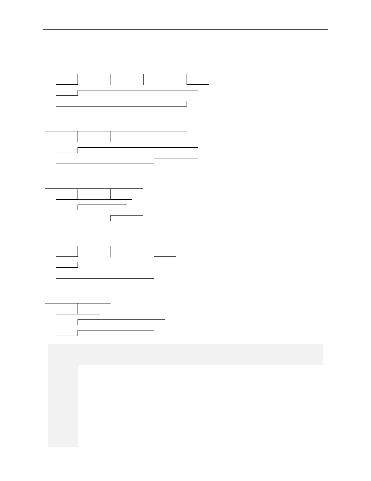
The following shows the actions of DCD and DSR as viewed at the RS232 connect or (inverted from pins)
during the connection process under different conditions.
1) Mode V22bis, Protocol enable d (through S25), Extended result co des.
2) Mode V22bis, Protocol enable d (through S25), Normal result codes.
3) Mode V22bis, Protocol enable d (through S25), No result codes.
4) Mode V22bis, No Protocol, Extended result codes.
5) Mode V22bis, No Protocol, No result codes.
O On-Line
O1
O2 Enables the modem to respond to a remote request for retrain
O3 Disables the modem to respond to a remote request for retrain
O4 Enables speed negotiation
O5 Disables speed negotiation
12 Rev. 1.5
O0
O[1-7] Retrain
Page 13

UG_1x22_043 V.22 bis Linux Softmodem for 73M1x22 Mi cr oDA A User Guide
The O[n] command is used to go back on-line when the command state was entered by
Note: If commands O0 or O1 are given to the modem while not connected, it will respond
with ERROR.
Causes the modem to pulse dial.
conjunction with the dial command, or alone, to designate
the method used for subsequent dialing.
DTR
Modem goes on-hook (hangs up), disables the Auto Answer mode, and
transitions from ON to OFF.
Turning
back ON will enable auto-Answer mode.
Enable V.23 Turnaround in Master Mode (On to Off
transition starts the
turnaround). Turnaround is done via
in all other R command settings.
The R[n] command selects how the Data Terminal Ready (
) signal is used by the
modem.
O6 Enables rate change to 1200 bps
O7 Enables rate change to 2400 bps
issuing the +++ escape sequence or turning DTR from ON to OFF with the appropriated SRegister setting in effect. The O[n] command applies only to asynchronous operation.
P Pulse Dial
The P modifier can be issued in
Q Result Codes Control
Q1 Result codes disabled
Refer also to the V[n] and X[n] commands.
Q0
Result codes enabled
R Data Terminal Ready (
R1 Modem assumes the Command State when DTR transitions from ON to OFF
R2
R3 Modem is reset when DTR transitions from ON to OFF
R4
R5 Power Down with DTR toggle (need hard reset)
R0 Modem ignores DTR
assumes the Command State when DTR
DTR
) Action
DTR
RTS
Rev. 1.5 13
DTR
Page 14

V.22 bis Linux Softmodem for 73M1x22 MicroDAA User Guide UG_1x22_043
S[r]?
The S[r]? command requests the modem to report the current value
These registers are used to set up various operating
parameters of the modem as explained in Chapter 5. The value
reported is in decimal notation.
S[r]$
The S[r]$ command requests the modem to report the current value
of register [r]. The value reported is in hexadecimal notation.
S[r]???
The S[r]???… command requests the modem to report the current
value of [r] and successive registers. The values are reported in
decimal notation. The number of registers reported corresponds to
? (question marks) given to the modem. For an
example: S10??? will report the values stored in the registers S10,
S11, S12.
S[r]$$$
The S[r]$$$… command requests the modem to report the current
rted in
hexadecimal notation. The number of registers reported
corresponds to the number of $ (dollar signs) given to the modem.
For an example: S10$$$ will report the values sto red in the registers
S10, S11, S12.
S[r]=[n]
S[r]=[n] Set S-Register Value r = 0 to 104 n = 0 to 255
The S[r]=[n] command allows you to set (modify) the value of any of
register [r] to new value [n]. The value [n] is entered in decimal
notation.
S[r]=n.$n.n.$n…
The S[r]=n.$n.n.$n… command allows you to set (modify) the value
of any of [r] and successive registers to the new values n (decimal
notation) or $n (hexadecimal notation). For an example:
S10=$F0.128.$EC.25 will set register S10=F0 (hexadecimal),
S11=128 (decimal), S12=EC (hexadecimal), and S13=15 (decimal).
l hexadecimal values must be entered in as a two digit hex value. For
example enter $0A instead of $A.
S[r]+[n]
The S[r]+[n] command sets bits in [r] S register by ORing the [n]
value and the value currently in the S Register.
S[r]-[n]
The S[r]+[n] command clears bits in [r] S register by ANDing the [not
n] value and the value currently in the S Register. All bits set in the
mask [n] will be cleared in the S register.
Causes the modem to tone dial.
conjunction with the dial command, or alone, to designate
the method used for subsequent dialing.
S S Register Monitoring
of register [r].
the number of
value of [r] and successive registers. The values are repo
T Tone Dial
The T modifier can be issued in
Al
14 Rev. 1.5
Page 15

V.22BIS Linux Softmodem for 73M1x22 MicroDAA User Guide UG_1x22_043
Y0
Asynchronous mode. No speed buffering, no prot ocol.
Y1
Synchronous mode. No speed buffering, no protocol.
Y4
Quasi-Synchronous mode. Allows the transmis sion and reception of
Y6
Asynchronous with speed buffering. Allows fix ed DTE-DCE speed so
connection results.
V Verbose/Numeric Result Codes Selection
V0 Numeric result codes – Format <CR>digit(s)<CR>
V2 Numeric result codes - Format <CR><LF>digit( s)<CR><LF>
Refer also to the Q[n] and X[n] commands
V1 Verbose result codes – Format <CR><LF>word< CR><LF>
Y Asynchronous/Synchronous Mode Selection
synchronous data through an asynchronous DTE by stripping off start and stop
bits on transmission and adding them on reception (See V42 operation).
applications do not need to change the communications rate based on
15 Rev. 1.4
Page 16

V.22 bis Linux Softmodem for 73M1x22 MicroDAA User Guide UG_1x22_043
W0
Do not return extended result codes (40-80). The message CONNECT followed
by the data rate between the DTE and the modem wi ll be sent to the DTE
W1
The CONNECT message will report the DTE speed then enable the carrier and
extended result codes
W2
The CONNECT message will report the DCE speed. All extended result codes
are disabled
W Extended Result Codes Selection
0 OK 13 CONNECT 7200
1 CONNECT 14 LINE-IN-USE
2 RING 22 CONNECT 75/1200
3 NO CARRIER 23 CONNECT 1200/75
4 ERROR
5 CONNECT 1200 40 CARRIER 300
6 NO DIALTONE 41 CARRIER 600
7 BUSY 44 CARRIER 1200/75
8 NO ANSWER 45 CARRIER 75/1200
9 CONNECT 600 46 CARRIER 1200
10 CONNECT 2400 47 CARRIER 2400
11 CONNECT 4800 70 PROTOCOL:NONE
Result codes
Numeric
value
Verbose
value
Numeric
value
Verbose
value
Extended Results Codes:
12 CONNECT 9600 77 PROTOCOL:LAP-M
16 Rev. 1.5
Page 17

UG_1x22_043 V.22 bis Linux Softmodem for 73M1x22 MicroDAA User Guide
14
+ ext.
0, 2, 4, 6, 14
0, 2, 4, 6, 14 +
0, 2, 4, 6, 14
0 – 1, 3 – 5,
0–1, 3–5,
+ ext.
0–1, 3–5,
0, 2 – 4, 14
0, 2 – 4, 14
0, 2 – 4, 14
0 – 1, 3 – 5, 7,
0–1, 3–5, 7,
+ ext.
0–1, 3–5, 7, 9-
0, 2, 4, 6, 14
0, 2, 4, 6, 14 +
0, 2, 4, 6, 14
0 – 1, 3 – 5, 7,
0–1, 3–5, 7,
+ ext.
0–1, 3–5, 7,
0, 2 – 4, 7, 14
0, 2 – 4, 7, 14
0, 2 – 4, 7, 14
0 – 1, 3 – 5,
0–1, 3–5, 9–
+ ext.
0–1, 3–5,
0, 2, 4, 6 - 7,
0, 2, 4, 6 - 7,
0, 2, 4, 6 - 7,
0 – 1, 3 – 5,
0–1, 3–5, 9–
0–1, 3–5,
0, 2 – 4, 7, 14
0, 2 – 4, 7, 14
0, 2 – 4, 7, 14
0 – 1, 3 – 5, 7,
0–1, 3–5, 7,
0–1, 3–5, 7, 9-
0, 2, 4, 6 - 7,
0, 2, 4, 6 - 7,
0, 2, 4, 6 - 7,
0 – 1, 3 – 5, 7,
0–1, 3–5, 7,
0–1, 3–5, 7, 9-
X Result Codes Set and Dialing Capabilities Selection
X0 Enable Result Codes 0-4, 14
X1 Enable Result Codes 0-5, 10-14
X2 Enable Result Codes 0-6, 10-14
X3 Enable Result Codes 0-5, 7, 10-14
X4 Enable Result Codes 0-7, 10-14
X5 Enable Result Codes 0-5, 10-14 and detect BUSY at OF F HOOK
X6 Enable Result Codes 0-6, 10-14 and detect BUSY at OF F HOOK
X7 Enable Result Codes 0-5, 7, 10-14 and detect BUSY at OF F HOOK
X8 Enable Result Codes 0-7, 10-14 and detect BUSY at OFF HOOK
See Result Codes table under W command.
X0
X1
X2
X3
X4
W0 W1 W2 W0 W1 W2
0, 2 – 4, 14 0, 2 – 4, 14 0, 2 – 4, 14 0 – 1, 3 – 4,
0, 2 – 4, 14 0, 2 – 4, 14
Pre Dial Post Dial
0–1, 3–4, 14 0–1, 3–4, 14
+ ext.
ext.
+ ext.
ext.
0, 2 – 4, 14 0 – 1, 3 – 5,
9 – 14, 22, 23
9 - 14, 22, 23
9 - 14, 22, 23
9 - 14, 22, 23
0–1, 3–5,
9–14, 22, 23
9–14, 22, 23
9–14, 22, 23
9–14, 22, 23
0–1, 3–5,
9-14, 22, 23
9-14, 22, 23
4, 22, 23
9–14, 22, 23
X5
X6
X7
X8
14
14
+ ext.
14 + ext.
+ ext.
14 + ext.
14
14
9 - 14, 22, 23
9 - 14, 22, 23
9 - 14, 22, 23
9 - 14, 22, 23
14, 22, 23
14, 22, 23
+ ext.
9–14, 22, 23
+ ext.
9–14, 22, 23
+ ext.
9-14, 22, 23
9-14, 22, 23
14, 22, 23
14, 22, 23
Rev. 1.5 17
Page 18

V.22 bis Linux Softmodem for 73M1x22 MicroDAA User Guide UG_1x22_043
Y0
Asynchronous mode. No speed buffering, no prot ocol.
Y1
Synchronous mode. No speed buffering, no protocol.
Y4
Quasi-Synchronous mode. Allows the transmis sion and reception of
bits on transmission and adding them on reception (See V42 operation).
connection results.
The Z command resets the modem. The Z command is equivalent to a power cycle.
Additional commands are not allowed in the command string.
The @C[r]=[n] command allows you to set (modify) the
or hexadecimal($ prefix) notation.
The @C[r]=n.$n.n.$n… command allows y ou to set
$0A instead of $A.
Register.
the Register.
the register.
Y Asynchronous/Synchronous Mode Selection
Y6 Asynchronous with speed buffering. Allows fix ed DTE-DCE speed so
synchronous data through an asynchronous DTE by stripping off start and stop
applications do not need to change the communications rate based on
Z Reset
@C Configure Registers
The @C command modifies the MicroDAA register value.
@C[r]=[n], Set Register Value r =
0 to 31($1F), n = 0 to 255($FF)
value of any of MicroDAA register [r] to new value [n].
The value [n] and [r] can be either in decimal(n o prefix)
@C[r]=n.$n.n.$n… command
allows you to set (modify) the
value of any of [r] and successive
registers to the new values n
(decimal) or $n (hexadecimal).
@C[r]+[n] command sets bits in
[r] register by ORing the [n] value
and the value currently in the
@C[r]-[n] command clears bits in
[r] register by ANDing the [not n]
value and the value currently in
@D Dump Registers
The @D command dumps entire MicroDAA registers.
(modify) the value of any of [r] and successive registers
to the new values n (decimal) or $n (hexadecimal). For
an example: @C$10=$0F.128.$EC.25 will set Register
$10=$F0, Register $11=128 (decimal), Register
$12=$EC and S13=15 (decimal).
must be entered in as a two digit hex value. For example enter
The @C[r]+[n] command sets bits in [r] regi st er by
ORing the [n] value and the value currentl y in the
Register.
The @C[r]-[n] command clears bits in [r] register by
ANDing the [not n] value and the value currentl y in the
Register. All bits set in the mask [n] will be cleared in
All hexadecimal values
18 Rev. 1.5
Page 19

UG_1x22_043 V.22 bis Linux Softmodem for 73M1x22 MicroDAA User Guide
Terminates the softmodem application gracefully and goes to Linux prompt.
root directory.
During a data connection, the escape command (+++) returns you to Command state
terminating the data connection so you can enter AT commands. The TSC
Softmodem supports the TIES (Timing Independent Escape Sequence) escape, not the
patented Hayes escape. The +++ must be followed by a valid AT command for the escape
AT command follows the +++, the modem will return to the data
line
command state.
@L[n] Set Lease Line Operation
Lease line operation is des ignated by S89 bit 2
n = 1 Sets lease line bit
n = 0 Clears lease line bit
@Z Escape to OS
To return to Softmodem application from t he li nux prompt, type “tsc_1922_CRLF” from the
+++ Escape Sequence
without
to be recognized. If a nonmode. Giving the TSC Softmodem a “+++AT” is also valid for escaping to the on-
Rev. 1.5 19
Page 20

V.22 bis Linux Softmodem for 73M1x22 MicroDAA User Guide UG_1x22_043
2.2 S-Registers
2.2.1 S-Register Overview
The S register set found in the TSC Softmodem is modeled after the Hayes S-registers, but differ in m any
respects. The Hayes register set has evolv ed over time to support added features, and the TSC
Softmodem has many features not found in ot her m odems. As is true for the AT commands, the Hayes
format is loosely followed, but it should not be assumed that software driver configurations written for
another modem will work without some modificati ons. Closely examine the register set and assure the
commands sent to the TSC Softmodem will giv e the intended actions.
The S-Registers allow you to customize the modem's operation. For example, you can use S-Registers
to determine how many times the telephone will ring before the modem answers, how long the modem
will wait for a dial tone before aborting a dialing sequ ence, how long the modem will pause during a
"pause" command, and so on. S-Registers are chang ed with the S[r]=[n] command.
You can check your S-Register settings any time you are in Command State. To check an S-Register
setting, enter a command consisting of the S-Register you want to check followed by a question mark.
For example, to check how long the modem will wait for a di al tone before aborting a call, type in the
following command:
AT S6? <Enter>
The screen will display the current settin g of S-Register S6.
To change an S-Register setting, enter a command consisting of the S-Register, an equal (=) sign, and
the desired value (in decimal). For example, t o set the modem to answer after three rings, type the
following command:
AT S0=3 <Enter>
Note: For more details on the commands to check or modify S-Registers see the S command under the
paragraph “AT” command set.
List Of S-Registers
The S-Registers you can change with the S[r] =[ n] command, or whose value you can check with the S[r]?
command, are listed below:
20 Rev. 1.5
Page 21

UG_1x22_043 V.22 bis Linux Softmodem for 73M1x22 MicroDAA User Guide
This register specifies the ring on which the modem will answer. A value of 1 to 255 will
answer mode and cause it to answer on that many rings
detected.
When the modem is set for Auto-Answer, register S1 keeps track of the number of times
on time, the S1 register is reset to 0 after the sum of
S56 and S58 seconds has elapsed.
2.2.1.1 TR30.2-Style Contr ol and Status Registers
S0 Auto Answer
n 0 –255
1-255 Auto answer mode on selected number of rings
0 Auto answer disabled
place the modem in auto-
S1 Ring Count
n 0 –255
0 No valid rings detected
the phone rings. After the end of ring-
S2 Escape Code Character
n 0 – 127 (ASCII)
>127 Escape feature disabled
43 ASCII “+”
S3 Carriage Return Character
n 0 – 127 (ASCII)
This character terminates both the command line and the result codes.
Rev. 1.5 21
13 <CR>
Page 22

V.22 bis Linux Softmodem for 73M1x22 MicroDAA User Guide UG_1x22_043
When X0, X1 or X5 mode is selected, the modem will dial after the time set in S6 has
elapsed since going off hook.
The S7 register performs two functions. It sets the maximum time between dialing and
responding to an incoming carrier signal. It also sets the duration of the pause generated
by the W dial string modifier.
S4 Line Feed Character
n 0 –127 (ASCII)
0 Suppress <LF> after the <CR> in a resul t code
Applicable only when verbose mode (V1) is selected.
10 <LF>
S5 Backspace Character
n 0 –32 and 127 (ASCII)
S6 Wait Before Blind Dial
n 1 – 255 seconds
8 <BS>
Country selection
dependent (S99)
2 2 seconds
S7 Wait For Carrier After Dial
n 0 – 254 seconds
50 50 seconds
22 Rev. 1.5
Page 23

UG_1x22_043 V.22 bis Linux Softmodem for 73M1x22 MicroDAA User Guide
The S8 register sets the number of seconds the modem will pause during a pause created
The effective time will range from (n-1) to n se conds.
The S9 register sets how long a carrier signal must exist before the modem issues a
line state is governed by the times
specified by S9 and S10. The DCD is the carrier detect indicator. If the carrier signal goes
off, DCD goes off within 20 ms. If the carrier returns, CD turns on within 20 ms after the
y for the time specified by S9. If CD is off for the time
specified by S10, then carrier is lost and the modem hangs up. If S10 is set to 255, the
modem will not hang up.
The S10 register sets (in 10ths of a second) the delay time between loss of carrier and the
modem hanging up. After the S10 delay time, the modem hangs up and returns to
Command State and the modem sends the NO CARRIER response.
S8 Pause Time For Comma
n 1 – 254 seconds
2 2 seconds
by a "," (comma) in the dialing sequence.
S9 Carrier Detect Response Time
n 1 – 254 in 100 ms unit
6 600 ms
carrier detect response.
Note: Carrier detection while the modem is in the on-
carrier has been on continuousl
S10 Lost Carrier Hang Up Delay
n 0 – 254 in 100ms unit
255 Carrier detect status ignored, no hang up
14 1.4 second
Rev. 1.5 23
Page 24

V.22 bis Linux Softmodem for 73M1x22 MicroDAA User Guide UG_1x22_043
S99 provides an easy way to set up the TSC Softmodem for different countries with a
single command. This command sets the dial tone and busy tone detection parameters as
well as the DTMF and pulse timing, DCIV settings, and AC impedance. Normally no other
commands are required to match a selected country’s requirements. Transmission levels
and detection threshold can be adjusted through other S registers compensate if your DAA
registers, it should be set at the beginning of the AT
string, but never preceding the F command (i.e. A T FS99=1… is OK, but not ATS99=44F)
tones for tone dialing. (Setting this
value lower than 50 may produce inaccurate dialing.) This register does not affect pulse
dialing.
Country selection
Country support
S99 Preset Country Selection
0 CTR21
33 France
34 Spain
39 Italy
44 United Kingdom
49 Germany
61 Australia
81 Japan
86 China
886 Taiwan
82 S. Korea
1 USA / Canada
specifications require further changes.
Since the S99 register affects multiple
Originate functions
Dialing functions
S11 DTMF Ton/Toff Dialing Speed
n 20 – 211 in ms
24 Rev. 1.5
70 Ton = Toff = 70 ms
The S11 register sets the duration and spacing of touch-
dependent (S99)
Page 25

UG_1x22_043 V.22 bis Linux Softmodem for 73M1x22 MicroDAA User Guide
Selects the digit to be dialed as well as the desired twist between the low and the high
filled
For test operation, both the twist and the digit must be filled. See J
command.
S12 DTMF / Twist Dial Register
N/A Twist 2 Twist 1 Twist 0 DTMF3 DTMF2 DTMF1 DTMF0
0 0 0 1 1 697 1209
0 0 1 0 2 697 1336
0 0 1 1 3 697 1477
0 1 0 0 4 770 1209
0 1 0 1 5 770 1336
0 1 1 0 6 770 1477
0 1 1 1 7 852 1209
1 0 0 0 8 852 1336
32 D digit selected, 2dB twist.
frequency. For normal operation, only the twist needs to be set once. The digit will be
automatically.
Bit 7 Bit 6 Bit 5 Bit 4 Bit 3 Bit 2 Bit 1 Bit 0
DTMF3 DTMF2 DTMF1 DTMF0 Digit Low tone High Tone
0 0 0 0 D 941 1633
1 0 0 1 9 852 1477
1 0 1 0 0 941 1336
1 0 1 1 * 941 1209
1 1 0 0 # 941 1477
1 1 0 1 A 697 1633
1 1 1 0 B 770 1633
1 1 1 1 C 852 1633
0 0 0 No twist, 0 dB nominal.
0 0 1 low frequency 1 dB below the high frequency tone.
0 1 1 low frequency 3 dB below the high frequency tone.
1 0 0 low frequency 4 dB below the high frequency tone.
1 0 1 low frequency 5 dB below the high frequency tone.
1 1 0 low frequency 6 dB below the high frequency tone.
1 1 1 low frequency 7 dB below the high frequency tone.
Twist2 Twist1 Twist0 Relative level
0 1 0 low frequency 2 dB below the high frequency tone.
Rev. 1.5 25
Page 26

V.22 bis Linux Softmodem for 73M1x22 MicroDAA User Guide UG_1x22_043
Attenuation level can go from +4.0 dB to –11.0 dB fro m nom inal .
DTMF gain increments have to be a minimum of 1dB, while for CP/Data the minimum is
2dB gain increments.
This coefficient affect the transmit value, thus the overall transmit level of the DTMF tones,
sent to the DAC. A higher value, yet increasing the DTMF level transmitted, also increases
Refer to the “Transmit levels at 3.3V operations” application note for further details.
S13 DTMF-Data / Transmit Attenuation
0 0 1 0 X 0 1 0 +4.0 dB
1 0 1 0 X 0 1 0 +3.0 dB
DTMF 0 0 0 1 X 0 0 1 +2.0 dB
1 0 0 1 X 0 0 1 +1.0 dB
CP/Data 0 0 0 0 X 0 0 0 0.0 dB
1 0 0 0 X 0 0 0 -1.0 dB
0 1 1 1 X 1 1 1 -2.0 dB
1 1 1 1 X 1 1 1 -3.0 dB
0 1 1 0 X 1 1 0 -4.0 dB
1 1 1 0 X 1 1 0 -5.0 dB
16 0dB nominal for call progress and data, +2dB nominal for DTMF
DTMF CP / Data Level
Bit 7 Bit 6 Bit 5 Bit 4 Bit 3 Bit 2 Bit 1 Bit 0 Gain/Atten
0 1 0 1 X 1 0 1 -6.0 dB
1 1 0 1 X 1 0 1 -7.0 dB
0 1 0 0 X 1 0 0 -8.0 dB
1 1 0 0 X 1 0 0 -9.0 dB
0 0 1 1 X 0 1 1 -10.0 dB
1 0 1 1 X 0 1 1 -11.0 dB
S85 DTMF- DAC transmit level coefficient
n 60 – 127
60 Default value.
the level of signal distortion. This coefficient only affects DTMF transmission.
26 Rev. 1.5
Page 27

UG_1x22_043 V.22 bis Linux Softmodem for 73M1x22 MicroDAA User Guide
Country selection
Country selection
Country selection
S32 Pulse Dial Make Time
n 1 – 211 in ms unit
39 39 ms
S33 Pulse Dial Break Time
N 1 – 211 in ms unit
61 61 ms
S34 Pulse Dial Inter-digit Time
N 1 – 211 in 10 ms unit
75 750 ms
dependent (S99)
Country selection
dependent (S99)
dependent (S99)
S72 Pulse Map \ CID control \ Black Listing control
64 10 pulses for 0; D pulses for D from 1 to 9; no CID, no blacklisting
dependent (S99)
Bit 1-0
00 10 pulses for 0; D pulses for D from 1 to 9
01 10 pulses for 0; 10-D pulses for D from 1 to 9
10 D+1 pulses for D from 0 to 9
Bit 2 Set user control on V24 outputs (CTS, RI…) – See Application Notes -
Bit 3 Enables CID wetting pulse through RELAY signal
Bit 4 Japanese Caller ID – Off hook CID processing Bit 5 Japanese Caller ID – Marks start the CID preamble -
Bit 6 Reserved
Bit 7 Black Listing option enabled
Sets the relation between the digit D and the digi t pulse dialed.
Rev. 1.5 27
Page 28

V.22 bis Linux Softmodem for 73M1x22 MicroDAA User Guide UG_1x22_043
Enables control over what the modem will qualify as answer tone. By default, the modem
functions as it has in the past. (Default = $35)
S92 Status Register 4
Bit Value
Bit 0 Reserved
Bit 1 Reserved
Bit 2 0 Pulse dialing disabled
All others bits are reserved.
4 pulse dialing allowed.
1 Pulse dialing enabled
S86 Flash (!) / On Time
n 1 – 211 in 10 ms unit
50 500 ms
S87 Flash (!) / Off Time
n 1 – 211 in 10 ms unit
50 500 ms
Note:
See also S14 and S22
S120 Accepted Answer Tone Frequencies
Bit 1 1300Hz – V23 Marks
Bit 3
Bit 0 1650Hz – V21 Marks (default)
Bit 2 2100Hz – ITU Answer Tone (default)
Reserved
28 Rev. 1.5
Bit 4 2225Hz – Bell Answer Tone (default)
Page 29

UG_1x22_043 V.22 bis Linux Softmodem for 73M1x22 MicroDAA User Guide
The value of this register extends the answer tone qualific ation time beyond the 155ms minimum in
10ms units.
S29 Extended Result Code/ Cadence Status
Do not return extended result codes (40 - 80). The message
CONNECT followed by the data rate between the DTE and the
modem will be sent to the DTE (W0 command)
The CONNECT message will report the DTE speed then enable the
carrier and extended result codes (W1 command)
The CONNECT message will report the DCE speed. All extended
result codes are disabled (W2 command)
Country selection
Bit 5 2250Hz – S0 (default)
Bit 6 Reserved
Bit 7 Reserved
S121 Answer Tone Qualify Time
n 0-255, but do not over-extend to maintain stability.
Call progress functions
dependent (S99)
Bit1/0
01
10
11 Connection messages are muted
Bit 2 X Reserved
Bit 3 0 Escape sequence disabled
1 Dual cadence for dial tone
1 Dual cadence for busy tone
1 Dual cadence for busy ring
136 See following. A bit set to 1 selects the function.
Bit 1/0 00
1 Escape sequence enabled
Bit 4 0 Alternate cadence for dial tone
Bit 5 0 Alternate cadence for busy tone
Bit 6 0 Alternate cadence for ring
Bit 7 0 Continuous dial tone disabled
Rev. 1.5 29
1 Continuous dial tone enabled
Page 30

V.22 bis Linux Softmodem for 73M1x22 MicroDAA User Guide UG_1x22_043
CLI 125 mS AT command delay enabled (disable this option for faster response
time to AT commands).
Country selection
Country selection
Country selection
S73 Configuration and Status Register 1
32 Sets different configuration. A bit set to 1 selects the function.
Bit 0 Enable teletel SEP codes in V.23 PAVI mode
Bit 1 Low power standby idle mode enabled
Bit 2 Reserved
Bit 3 Reserved
Bit 4 Reserved
Bit 5
Bit 6 Adaptive dialing enabled
Bit 7 Reserved
S66 Dial Tone / Wait For Dial Tone Time
n 1 – 254 in second
8 8 seconds
Sets the maximum number of seconds the modem waits for dial tone.
S67 Dial Tone / Qualify Dial Tone Time
n 0 – 254 in 10 ms unit
120 1.2 second
Sets the minimum duration for dial tone.
S35 Dial Tone / Cadence A Minimum On Time
n 0 – 255 in 40 ms unit
0 0 ms
dependent (S99)
dependent (S99)
S36 Dial Tone / Cadence A Maximum On Time
n 0 – 255 in 40 ms unit
30 Rev. 1.5
dependent (S99)
Page 31

UG_1x22_043 V.22 bis Linux Softmodem for 73M1x22 MicroDAA User Guide
Country selection
Country selection
Country selection
Country selection
0 0 ms
S37 Dial Tone / Cadence A Minimum Off Time
n 0 – 255 in 40 ms unit
0 0 ms
S38 Dial Tone / Cadence A Maximum Off Time
n 0 – 255 in 40 ms unit
0 0 ms
S39 Dial Tone / Cadence B Minimum On Time
n 0 – 255 in 40 ms unit
0 0 ms
dependent (S99)
dependent (S99)
dependent (S99)
S40 Dial Tone / Cadence B Maximum On Time
n 0 – 255 in 40 ms unit
0 0 ms
S41 Dial Tone / Cadence B Minimum Off Time
n 0 – 255 in 40 ms unit
0 0 ms
S42 Dial Tone / Cadence B Maximum Off Time
n 0 – 255 in 40 ms unit
0 0 ms
Country selection
dependent (S99)
dependent (S99)
Country selection
dependent (S99)
Rev. 1.5 31
Page 32

V.22 bis Linux Softmodem for 73M1x22 MicroDAA User Guide UG_1x22_043
Country selection
Country selection
Country selection
Country selection
S23 Busy Detection Cadence Cycle Count
3 3 busy cadence cycles selected.
Defines how many busy cadence cycles before se nding the busy result code.
S43 Busy Tone / Cadence A Minimum On Time
dependent (S99)
n 0 – 255 in 40 ms unit
10 400 ms
S44 Busy Tone / Cadence A Maximum On Time
Country selection
dependent (S99)
n 0 – 255 in 40 ms unit
15 600 ms
S45 Busy Tone / Cadence A Minimum Off Time
n 0 – 255 in 40 ms unit
10 400 ms
S46 Busy Tone / Cadence A Maximum Off Time
n 0 – 255 in 40 ms unit
15 600 ms
S47 Busy Tone / Cadence B Minimum On Time
n 0 – 255 in 40 ms unit
0 0 ms
dependent (S99)
dependent (S99)
dependent (S99)
32 Rev. 1.5
Page 33

UG_1x22_043 V.22 bis Linux Softmodem for 73M1x22 MicroDAA User Guide
Country selection
Country selection
Country selection
Country selection
S48 Busy Tone / Cadence B Maximum On Time
dependent (S99)
n 0 – 255 in 40 ms unit
0 0 ms
S49 Busy Tone / Cadence B Minimum Off Time
n 0 – 255 in 40 ms unit
0 0 ms
S50 Busy Tone / Cadence B Maximum Off Time
n 0 – 255 in 40 ms unit
0 0 ms
S20 Call Progress Selection
dependent (S99)
dependent (S99)
Country selection
dependent (S99)
17 Imprecise tones detection only.
Busy tone bits 7-4/ Dial tone bits 3-0
Bit 7/3 Bit 6/2 Bit 5/1 Bit 4/0 Function
0 0 0 1 Detect Imprecise tones ONLY.
0 0 1 0 Detect All Precise tones ONLY.
0 1 0 0 Detect Any of the Precise tones.
S88 Imprecise Filter Selection
Bits 3-0 Pre dial imprecise filter selection (di al tone)
Bits 7-4 Post dial imprecise filter selection (bu sy tone)
0 Filter 280-680Hz selected for pre and post dialing
Value
Frequency range
dependent (S99)
Rev. 1.5 33
Page 34

V.22 bis Linux Softmodem for 73M1x22 MicroDAA User Guide UG_1x22_043
Defines which precise tones constitute a dial tone and which constitute a busy tone
(related bit must be set to one). High nibble defines dial tone and low nibble defines busy.
See also S63.
0 280Hz – 680Hz
1 370Hz – 500Hz
2 240Hz – 580Hz
3 200Hz – 650Hz
15 User defined filter
S19 Precise Call Progress Selection
Country selection
dependent (S99)
195 350Hz and 440Hz are dial tones; 440Hz and 620Hz are Busy tones.
Bit 0 Selection of 350Hz as a dial tone
Bit 1 Selection of 440Hz as a dial tone
Bit 2 Selection of 480Hz as a dial tone
Bit 3 Selection of 620Hz as a dial tone
Bit 4 Selection of 350Hz as a busy tone
Bit 5 Selection of 440Hz as a busy tone
Bit 6 Selection of 480Hz as a busy tone
Bit 7 Selection of 620Hz as a busy tone
S63 Precise Call Progress Detect
0 See following.
Bit 0 Detected f0 (350 Hz).
Bit 1 Detected f1 (440 Hz).
Bit 2 Detected f2 (480 Hz).
Bit 3 Detected f3 (620 Hz).
Bit 4 Detected 2130 Hz.
Bit 5 Detected 2750 Hz.
Bit 6 Busy tone detection enabled.
Bit 7 Call Progress filter #1 detect bit.
34 Rev. 1.5
Page 35

UG_1x22_043 V.22 bis Linux Softmodem for 73M1x22 MicroDAA User Guide
S75 determines at what minimum level imprecise call progress tones are detected before
value corresponds to a lower signal level. The dBm level depends on the
DAA used.
S76 determines at what minimum level imprecise call progress tones are detected after
Refer to table under S75.
S77 determines at what minimum level precise call progress tones are detected before
Refer to table under S75.
Country selection
Country selection
S75 Pre Dial Call Progress Imprecise Detect Level
dependent (S99)
n 1 - 96
30 -45dBm threshold.
dialing. A larger
dBm0 S75-S78 dBm0 S75-S78 dBm0 S75-S78 dBm0 S75-S78
-25 3 -31 6 -37 12 -43 24
-26 3 -32 7 -38 14 -44 27
-27 4 -33 8 -39 15 -45 30
-28 4 -34 9 -40 17
-29 5 -35 10 -41 19
-30 5 -36 11 -42 22
S76 Post Dial Call Progress Imprecise Detect Level
n 1 - 96
30 -45dBm threshold.
dialing.
S77 Pre Dial Call Progress Precise Detect Level
n 1 - 96
30 -45dBm threshold.
dialing.
dependent (S99)
Country selection
dependent (S99)
Rev. 1.5 35
Page 36

V.22 bis Linux Softmodem for 73M1x22 MicroDAA User Guide UG_1x22_043
S78 determines at what minimum level precise call progress tones are detected after
dialing. Refer to table under S75.
7 128
V23
Country selection
S78 Post Dial Call Progress Precise Detect Level
n 1 - 96
30 -45dBm threshold.
dependent (S99)
S15 Calling Tone Off Time
n 0 – 255 in 100 ms unit
Calling tone is defined as a 1300Hz tone. See S28 / bit 7 for enabling/disabling calling tone
17 1.7 second
S16 Calling Tone On Time
n 0 – 255 in 10 ms unit
Calling tone is defined as a 1300Hz tone. See S28 / bit 7 for enabling/disabling calling tone
60 600 ms
Data functions
S30 Data Modulation Selection
Bit Value Mode
0 1 4-Wire mode
1 2 Bell202
4 16 Bell212
108
See following.
Precedence is from the highest to the lowest con nection data rate.
2 4 V22bis
3 8 V22
36 Rev. 1.5
5 32 Bell103
6 64 V21
Page 37

UG_1x22_043 V.22 bis Linux Softmodem for 73M1x22 MicroDAA User Guide
Allows programmable delay between completion of handshake and connect (ready for
ms increments. The Default delay times are as follows:
QAM Answer Mode = 200 ms
FSK Originate Mode = 300 ms
0
Selects V.23H 1200/75 bps Asymmetric Duplex mode.
1
Selects V.23H 1200 bps Half Duplex mode.
Bit 1-7
Reserved
S31 Data Modulation Status
0 1 Successful 4-Wire connection
1 2 Successful Bell 202 connection
2 4 Successful V22bis connection
3 8 Successful V22 connection
4 16 Successful Bell 212 connection
5 32 Successful Bell 103 connection
6 64 Successful V21 connection
7 128 Successful V23 connection
0 Default value until connection is established
Bit Value Mode
S119 Wait Bef ore Connect
data). User should be careful; Host will have to complete delay period before transmitting
data. Setting the value at this register will affect timing for all modes. Resolution is in 10
PSK Answer Mode = 770 ms
PSK Originate Mode = 770 ms
NOTE: Special mode when S119 = $FF (Default), uses same value of wait as in the past.
S124 V23 Half Duplex Enable
Enables half duplex “ping-pong” mode. (Default = 0)
Bit 0
Rev. 1.5 37
Page 38

V.22 bis Linux Softmodem for 73M1x22 MicroDAA User Guide UG_1x22_043
No protocol detection selected. Modem looks for ODP/ADP on connection.
This is used when the host does not do the initial protocol detection.
V42-LAPM protocol selected. This option enables the ODP/ADP
sequence detection support within the TSC Softmodem if not
supported by the host processor.
When a connection is made and the selected protocol is detected an appropriate result
PROTOCOL:
NONE or result code ‘70’ will be sent.
S79 determines at what minimum level carrier is detected for originating FSK. A larger
number corresponds to a lower signal level threshold.
is detected for answering FSK. A larger
number corresponds to a lower signal level threshold.
S81 determines at what minimum level carrier is detected for originating PSK. A larger
number corresponds to a lower signal level threshold.
S25 Protocol Selection
Bit 0 1 Disconnect if no protocol is detected
Bit 1 1
0
code is returned:
PROTOCOL: NONE or ‘70’
PROTOCOL: LAPM or ‘77’
If 1.5 seconds after CARRIER is established, and no protocol is detected,
S79 FSK Originate Carrier Detect Level
n 1 – 96
35 -45dBm threshold.
S80 FSK Answer Carrier Detect Level
n 1 – 96
35 -45dBm threshold.
S80 determines at what minimum level carrier
S81 PSK Originate Carrier Detect Level
n 1 – 96
40 -45dBm threshold.
38 Rev. 1.5
Page 39

UG_1x22_043 V.22 bis Linux Softmodem for 73M1x22 MicroDAA User Guide
S82 determines at what minimum level carrier is detected for answering PSK. A larger
number corresponds to a lower signal level threshold.
S83 determines at what minimum level carrier is detected for originating QAM. A larger
number corresponds to a lower signal level threshold.
S84 determines at what minimum level carrier is detected for answering QAM. A larger
number corresponds to a lower signal level threshold.
This register sets the Inactivity timeout for data mode. If there is no transmitted or received
S82 PSK Answer Carrier Detect Level
n 1 – 96
35 -45dBm threshold.
S83 QAM Originate Carrier Detect Level
n 1 – 96
40 -45dBm threshold.
S84 QAM Answer Carrier Detect Level
n 1 – 96
35 -45dBm threshold.
S117 Inactivity Timeout
n 0 – 255 in seconds
0 Feature disabled
data for the duration of this timer the modem wil l terminate the call.
Rev. 1.5 39
Page 40

V.22 bis Linux Softmodem for 73M1x22 MicroDAA User Guide UG_1x22_043
Black Listing function
S105 Pre Call attempt delay
n 1 – 254 in seconds
Delay prior attempting a call (after an ATD… com m and is issued)
5 5 seconds
S106 Delay between 1st and 2nd attempt
n 1 – 254 in seconds
Delay between 1st and 2nd call attempt to the same number in a series.
5 5 seconds
S107 Delay between Nth and N+1th attempt
n 1 – 254 in seconds
Delay between Nth and N+1th call attempt to the same number in a series.
60 60 seconds
S108 Maximum successive failed attempts
N 1 – 254 in unit
Sets the maximum number of successive failed call attempts allowed.
15 15 consecutive failed call attempts
40 Rev. 1.5
Page 41

UG_1x22_043 V.22 bis Linux Softmodem for 73M1x22 MicroDAA User Guide
This register controls the ring amplitude threshold and selects hardware or software ring
detection. (Default = 0)
Ring Amplitude Detection Threshold. Lower v al ue detects lower amplitude ring
signal.
1 = No frequency checking, enables phonex operat i on
0 = Frequency and amplitude checking, normal operation.
Auto detect phonex mode, the modem will automatically detect an user phonex
system and configure itself accordingly.
Force soft ring detection with frequency qualification for non-Phonex operation.
Recommend value of 7 (or 2 for very Low Amplitude and Frequency detection).
Force soft ring detection with no frequency quali fication for Phonex operation.
Recommend value of 170.
Assumes a half wave detection circuit.
Note: The values need to be doubled if a full wave detector is used.
Country selection
S109 Delay between series
N 0 – 254 in minutes
Sets the delay before another series of call attempts is allowed.
0 Disabled – only 1 series allowed
Answering functions
S123 Software Ring Detect
Bits 0-6
Bit 7
Special Values for S123:
=0 Disable soft ring detect, use hardware ring.
=255
=1–127
128–254
S17 Ring / Minimum Frequency Detection
n 0 – 253 in Hz
10 10 Hz
dependent (S99)
Rev. 1.5 41
Page 42

V.22 bis Linux Softmodem for 73M1x22 MicroDAA User Guide UG_1x22_043
Assumes a half wave detection circuit.
Note: The values need to be doubled if a full wave detector is used.
Country selection
Country selection
Country selection
Country selection
Country selection
S18 Ring / Maximum Frequency Detection
dependent (S99)
n 1 – 254 in Hz
75 75 Hz
S51 Ring / Cadence A Minimum On Time
dependent (S99)
n 0 – 255 in 40 ms unit
40 1.6 s
S52 Ring / Cadence A Maximum On Time
dependent (S99)
n 0 – 255 in 40 ms unit
60 2.4 s
S53 Ring / Cadence A Minimum Off Time
n 0 – 255 in 40 ms unit
80 3.2 s
S54 Ring / Cadence A Maximum Off Time
n 0 – 255 in 40 ms unit
120 4.8 s
S55 Ring / Cadence B Minimum On Time
n 0 – 255 in 40 ms unit
dependent (S99)
dependent (S99)
Country selection
dependent (S99)
0 0 ms
42 Rev. 1.5
Page 43

UG_1x22_043 V.22 bis Linux Softmodem for 73M1x22 MicroDAA User Guide
Caller ID.
Country selection
Country selection
Country selection
Country selection
S56 Ring / Cadence B Maximum On Time
n 0 – 255 in 40 ms unit
0 0 ms
S57 Ring / Cadence B Minimum Off Time
n 0 – 255 in 40 ms unit
0 0 ms
S58 Ring / Cadence B Maximum Off Time
n 0 – 255 in 40 ms unit
0 0 ms
dependent (S99)
dependent (S99)
dependent (S99)
S74 Billing Delay Time
dependent (S99)
n 20 – 254 in 100 ms unit
20 2 seconds
This register sets the duration of billing delay i n uni ts of 100 ms.
Caller ID functions
S95 Caller ID configuration
Bit 0 Dual Tone Alert Signal expected
Bit 1:2
Bit 4 Caller ID enabled. Applies only to On-Hook/Offline/Type I Caller ID.
136 CID disabled
Number (0-3) of Line Reversal or Ring Pulse Alert S i gnal s ex pected before
Bit 3 CID between 1st and 2nd ring
Bit 5 0= FS K , 1 = DTMF based signaling for CID
Bit 6 Enables using USR11 to measure DC offset when entering Idle state
Rev. 1.5 43
Page 44

V.22 bis Linux Softmodem for 73M1x22 MicroDAA User Guide UG_1x22_043
Bit 7
Enables using USR11 output to enable an external signal path for CID. Bit 7 = 0
sets continuous CID mode where S95 bits 0, 1, 2, and 3 are ignored. Also
signaling state for
LIU-E detection.
Special modes:
marks (Type 2 Snoop).
Disables ring interrupt detection for the specified period of time during CID enable/disable
transitions, measured in ms. Default = 20
VFI fast connect originate handshake when specifying Bell 212 only
in S30. This works for Bell 212A and V.22 when S30 is set only for
selected.
S95 = 0X01 0000B
S95 = 0X110000B
S95 = 10011001B
enables using USR 11 output to signal DAA to enter idle line
Continuous FSK Caller ID mode.
Continuous DTMF - send detec ted d igits to DTE w ithou t “CID :” me ssage.
Detect US Type 1 and Type2 Snoop CID simultaneously. In this mode the
modem may automatically modify S72 register bit 5 to loo k for Dots ( Type1) or
S118 Caller I D Ring Int er r upt Delay
=n is disable time in mS.
Line In Use and Parallel Pick Up detection functions
S89 Parallel Pick-up Energy Detection (Default=0)
0 PPU disabled
Bit Value
Bit 1,0 00-11 N command value
Bit 2 0 Reserved
Bit 3 1 PPU Energy (PPU-E) detection enabled
Bit 4 1 Inverts ring input polarity for PPU-V (Default is RingB active low)
Bit 5 1 Inverts ring input polarity for LIU-V (Default is RingB active low)
Bit 6 1
Bell 212A. Other modes cannot be specified in S30.
Will send FLAGS as part of the handshake when Y 1 or Y4 is
Bit 7 1 Reserved
S110 Line-In-Use/Parallel Pick Up Configuration Register
112 No LIU or PPU enabled.
Bit Value
Bit 0 1 Enables Off-Hook Voltage sensing Parallel pick-up det. (PPU-V)
44 Rev. 1.5
Page 45

UG_1x22_043 V.22 bis Linux Softmodem for 73M1x22 MicroDAA User Guide
Enables Call-Waiting Caller-ID option. This bit applies only to OffHook/Online/Type II Caller-ID.
hook LIU
Bit 7
1
Enables Long Space Disconnect. When enabled, the TSC
Softmodem sends 3.5 seconds of NULL characters before
disconnecting upon reception of an on hook command from the host;
reception of 1.5 second of NULL characters
from the remote modem.
This register sets the settling time to wait, after the LIU sensing circuit is enabled, before
hook
(PPU) detection.
Sets the Threshold for the voice Energy. Lower number means higher signal threshold.
The value of 0 would effectively never detect and higher than 95 would always detect. This
register is also use by (J7) test mode as a minimum carrier det ect threshold.
Bit 1 1 Enables On-Hook Line-In-Use Voltage sensing detection (LIU-V)
Bit 2 1 Enables On-Hook Line-In-Use Energy sensing detection (LIU-E)
Bit 3 1
Bit 4 1 Enables high impedance TXAN/TXAP while looking for CID
Bit 5 1 Enables receive gain (20 dB) while looking for CID
Bit 6 1
Enables using USER10 output to signal DAA to activate onsensing
and disconnects upon
S111 Line-In-Use Settling time
n 0 –254 in 10ms unit
20 200ms
sampling LIU signal. This is used for both on-hook (Voltage sensing LIU) and off-
S112 Line-In-Use Energy detection Wait
n 0 –254 in 100ms units
This register sets the qualify time that Energy must remain below threshold.
20 2 seconds
S113 Line-In-Use Energy Detection Threshold
n 0 – 95
60 Default value.
Rev. 1.5 45
Page 46

V.22 bis Linux Softmodem for 73M1x22 MicroDAA User Guide UG_1x22_043
This register sets the Threshold for PPU to detect loss of Energy compared to the energy
level at the time of connection.
S116 Parallel-Pick-Up Energy detection Threshold
n 72, 80, 90.
Value Energy loss detected
72 1 dB loss of energy detection
80 2 dB loss of energy detection
90 3 dB loss of energy detection
72 1 db energy loss threshold
S122 Parall el Pick Up Debounce Timer
Sets the duration of the parallel pick-up debounce timer in 10m s i ncrements.
=n times 10mS.
S14 General Modem Status Register 1
S14 reflects the status of certain options.
Bit Value
1 Receive channel speed buffered.
1 Double Dual cadence detection
Bit 1 0 No echo
1 Result codes disabled
170 See following.
In data mode
Bit 0 0 Clear channel for receiver.
In Call progress mode
Bit 0 0 Single cadence A or B detection
1 Echo on
Bit 2 0 Result codes enabled
Bit 3 0 Numeric result codes
46 Rev. 1.5
Page 47

UG_1x22_043 V.22 bis Linux Softmodem for 73M1x22 MicroDAA User Guide
Modem assumes the Command State when DTR transitions from
Modem goes on hook, disables Auto Answer and assumes the
Command State when DTR transitions from ON to OFF (Auto
Answer can be enabled by transitioning DTR from O FF to ON) (R2).
ON indicates the presence of CD (equivalent to C1 command).
1 Verbose result codes
1 First cadence of double cadence matched
Bit 5 0 Touch tone dialing
1 Connected
Bit 7 0 Answer
Bit 4 0 No match
1 Pulse dialing
Bit 6 0 Not connected
1 Originate
S21 General Modem Status Register 2
Bit Value
Bit 0 0 Keypress abort disable.
1 See following.
1 Keypress abort enable.
1 Use raw carrier detect (set by C2 command).
1 Enable V.23 turnaround via DTR toggl e (set by R4 command).
01
10
11 Modem is reset when DTR transitions from ON to OFF (R3).
1 DCD
1 RTS / CTS DTE flow control (equivalent to K3).
1 XON / XOFF DTE flow control (equival ent to K4).
Bit 1 0 Use debounced carrier detect
Bit 2 0 Disable V.23 turnaround via DTR toggle.
Bits 4/3 00 Modem ignores DTR (Default ) (R 0)
ON to OFF (R1).
Bit 5 0 DCD always ON (equivalent to C0 command).
Bit 6 0 No RTS / CTS DTE flow control.
Bit 7 0 No XON / XOFF DTE flow control.
Rev. 1.5 47
Page 48

V.22 bis Linux Softmodem for 73M1x22 MicroDAA User Guide UG_1x22_043
X5 Enable Result Codes 0-5, 10, and detect
BUSY at OFF HOOK.
X6 Enable Result Codes 0-6, 10, and detect
BUSY at OFF HOOK.
X7 Enable Result Codes 0-5, 7, 10, and
detect BUSY at OFF HOOK.
X8 Enable Result Codes 0-7, 10, and detect
BUSY at OFF HOOK.
S22 General Modem Status Register 3
0 0 0 Y0 Asynchronous mode
0 0 1 Y1 Synchronous mode
1 0 0 Y4 Pseudo-synchronous mode
0 0 0 1 X0 Enable Result Codes 0-4.
0 0 0 0 X1 Enable Result Codes 0-5, 10.
0 0 1 0 X2 Enable Result Codes 0-6, 10.
0 1 0 0 X3 Enable Result Codes 0-5, 7, 10.
1 0 0 0
1 0 1 0
54 See following
Bit 2 Bit 1 Bit 0 Synchronous/Asynchronous control
1 1 0 Y6 Asynchronous with speed buffering
Bit 6 Bit 5 Bit 4 Bit 3 Select result codes
0 1 1 0 X4 Enable Result Codes 0-7, 10. (Default)
1 1 0 0
1 1 1 0
Bit 7
1 Pulse dialing make/break ration = 33/67
0 Pulse dialing make/break ration = 39/61
S26 Data Mode Control Register
Bit 0 Forces rate change to 1200bps
1 Enables speed negotiation during a retrain request
1 Enables an automatic retrain request to be negotiated
0 See following
Bit 1 0 Disables speed negotiation during a retrain request
Bit 2 0 Disables automatic retrain requests
1 Enables the modem to respond to a retrain request
48 Rev. 1.5
Bit 3 0 Disables retrain request response
Page 49

UG_1x22_043 V.22 bis Linux Softmodem for 73M1x22 MicroDAA User Guide
Select 1800 Hz guard tone to be generated during answer mode
handshake
Select 550 Hz guard tone to be generated during answer mode
Order of precedence is as follows from highest to lowest: Bit 1, Bit 2, Bit3, Bit 4
1
1 Enables guard tone generation
1 Enable V.23 turnaround
1 Rx 1200 bps (Bell 202 and V.23 master m ode)
Bit 4 0
handshake
Bit 5 0 Disables guard tone generation
Bit 6 0 Disable V.23 turnaround
Bit 7 0 Tx 1200 bps (Bell 202 and V.23 slave mode)
S27 Call Progress Transmit Register
0 See following.
Bit 0 0 Send “0FFh” characters in pseudo sync (Y4)
1 Do not send “0FFh” characters in pseudo sync (Y4)
1 Transmit 1100Hz
1 Transmit 1300Hz
1 Transmit 2100Hz
1 Transmit 2225Hz
Bit 5 Disconnect bit
1 Bell 103, Bell 202, Bell 212A (B1 comm and)
1 Protocol selection done
Bit 1 0 Do not transmit 1100Hz
Bit 2 0 Do not transmit 1300Hz
Bit 3 0 Do not transmit 2100Hz
Bit 4 0 Do not transmit 2225Hz
Bit 6 0 CCITT V22bis, V22, V21, V23 (B0 command)
Bit 7 0 Protocol selection not done
Rev. 1.5 49
Page 50

V.22 bis Linux Softmodem for 73M1x22 MicroDAA User Guide UG_1x22_043
S28 Fast Connect Status and Calling Tone Enable Register
Bit 0 1 AGC enable
Bit 2 X Reserved
Bit 3 1 Synchronous mode (set by Y 1 and Y4)
Bit 4 1 Answer tone enable
Bit 7 1 Calling tone enable
50 See following.
Bit 1 X Reserved
Bit 5 1 Billing delay enable
Bit 6 1 400ms answer tone at 1200bps
S60 Test Control Register
0 See following
Bit 2 Bit 1 Bit 0 Function
0 0 0 Data mode
0 0 1 Send Marks
0 1 0 Send Spaces
0 1 1 Send Dotting
1 0 0 Send S1
1 0 1 Send S0
1 1 0 Send Dotting ‘A ’
1 1 1 Send Flags (07Eh)
Bit 3 1 Enable detection of dial tone
0 Disable detection of dial tone
1 Enables the scrambler
1 Enables the de-scrambler
Bit 6 1 Enable RLDB mode
0 Disable RLDB mode
Bit 7 1 Enable ALB mode
Bit 4 0 Disables the scrambler
Bit 5 0 Disables the de-scrambler
0 Disable ALB mode
50 Rev. 1.5
Page 51

UG_1x22_043 V.22 bis Linux Softmodem for 73M1x22 MicroDAA User Guide
Remote digital loopback detect bit. This bit will be set when a remote digital
loopback request has been detected.
Carrier detect bit. This bit will be set when conditions for V.24 circuit 104 (DCD)
have been met by the modulation mode being used.
Energy detect bit. This bit will be set if the receive level is above a certain
threshold.
S1 Detect bit. This will be set if S1 (unscrambled 110011..) is detected. This bit
USB1 Detect bit. This will be set if USB1 (unscrambled binary ones) is
detected. This bit is also used to detect a remote digital loopback request if
connected in V.22bis or V.22
Detected 1100 Hz (fax calling tone). Detect changes to 1270 Hz at the end of
answer Call Progress.
Detected 1300 Hz (data calling tone). Detect changes to 980 Hz at the end of
answer Call Progress.
S61 Signal detect Register 1
Bit 0 Reserved
Bit 1
Bit 2
Bit 3 Wait for Calling Tone before sending Answer Tone
Bit 4
Bit 5
Bit 6
Bit 7 Reserved
0 See following. Read only.
is also used to detect a retrain request if connected i n V.22bis or V.22
S62 Signal detect Register 2
Bit 0 Detected 1650 Hz (V.21 answer marks)
Bit 1 Detected 1300 Hz.
Bit 2 Detected 2100 Hz (ITU answer tone)
Bit 3 reserved
Bit 4 Detected 2225 Hz (Bell answer tone)
Bit 5 Detected 2250 Hz (comp. USB1).
Bit 6
Bit 7
Rev. 1.5 51
0 See following. Read only.
Page 52

V.22 bis Linux Softmodem for 73M1x22 MicroDAA User Guide UG_1x22_043
See following
Bit 7 indicates a valid DTMF detection. A register value of zero indicates no
0 indicate the
tone pair detected. Works with command J6 and bit 7 have to be set in order to
be valid. The following tables define DTMF decodin g:
Low Tone
(Hz)
High Tone
(Hz)
S65 DTMF Detect Register
0
detect for the polled application. Bits 6 - 4 are reserved. Bits 3 -
Valid N/A N/A N/A DTDET3 DTDET2 DTDET1 DTDET0
1 0 0 0 0 D 941 1633
1 0 0 0 1 1 697 1209
1 0 0 1 0 2 697 1336
1 0 0 1 1 3 697 1477
1 0 1 0 0 4 770 1209
1 0 1 0 1 5 770 1336
1 0 1 1 0 6 770 1477
1 0 1 1 1 7 852 1209
1 1 0 0 0 8 852 1336
1 1 0 0 1 9 852 1477
1 1 0 1 0 0 941 1336
1 1 0 1 1 * 941 1209
Bit 7 Bit 6 Bit 5 Bit 4 Bit 3 Bit 2 Bit 1 Bit 0
DTMF Detect bits Dialed Tone Pair Detected
Det Valid DTDET 3 DTDET 2 DTDET 1 DTDET 0 Digit
1 1 1 0 0 # 941 1477
1 1 1 0 1 A 697 1633
1 1 1 1 0 B 770 1633
1 1 1 1 1 C 892 1633
S68 Test Timer
Times how long the self-tests should run in seconds.
52 Rev. 1.5
0 0 second.
Page 53

UG_1x22_043 V.22 bis Linux Softmodem for 73M1x22 MicroDAA User Guide
When the N0 command has been issued, register S90 defines the time interval between an
ON. The S90 setting
applies to Synchronous modes only.
Sets the maximum carrier detect threshold used by (J7) test mode. Higher value may
indicate open circuit in either TXAP or TXAN signals to RXA. See S115.
Sets the maximum carrier detect threshold used by (J7) test mode. Higher value may
indicate open circuit in either TXAP or TXAN signals to RXA. See S114.
S69 Test Error Count
Keeps count of how many errors occur during t he self-test.
0 No error
S70 Auto Retrain Threshold
Forces auto retrain if threshold is below the m ean square error.
Default = 16
S90 RTS to CTS Turnaround Delay
n 0 – 255 in 10ms unit
2 20 ms turnaround delay
OFF to ON transition of RTS and when the modem turns CTS
S114 Maximum carrier detect threshold (High Byte)
n 0 - 255
80 Default value
S115 Maximum carrier detect threshold (Low Byte)
n 0 - 255
80 Default value
Rev. 1.5 53
Page 54

V.22 bis Linux Softmodem for 73M1x22 MicroDAA User Guide UG_1x22_043
2.3 Application Notes for the TSC Softmodem
54 Rev. 1.5
Page 55

UG_1x22_043 V.22 bis Linux Softmodem for 73M1x22 MicroDAA User Guide
A reset of the TSC Softmodem can be performed t hree different ways:
The TSC Softmodem has expanded call progress det ection capabilities. In addition to the
preset frequency filters. At least one range of frequencies will
meet the requirements for call progress detection worldwide. The selection of the filter that
dial phase (busy
Once the frequency filter has been chosen, the threshold of detection needs to be set
After the frequency ranges have been selected, the last step is to select the proper
cadence of the call progress tones we are about to detect. The TSC Softmodem features
dwide.
There are four different types of cadences defined in the TSC Softmodem. Each parameter
Resetting the TSC Softmodem
• A power-on reset
• Reset Button (similar to power on reset)
• Start the soft modem from Linux prompt
Call Progress Detection
capability of detecting some precise tones ( see S19), the TSC Softmodem implements
some imprecise call progress capabilities (wide frequency bandwidth filters). Each call
progress tone can be monitored and validated according to the following parameters:
• Frequency
• Level
• Cadence
The TSC Softmodem has 4
will apply during either the pre-dial phase (dial tone) or during the post-
tone) is made through the Imprecise filter tem plate register, S88.
The detection bandwidth of the preset filt ers are:
• 280Hz √ 680Hz
• 370Hz √ 500Hz
• 240Hz √ 580Hz
• 200Hz √ 650Hz
In addition, it is possible for a user defined f requency filter. Contact your local TERIDIAN
representative for further details on that function.
through registers S75 and S76. Due to the variety of requirements for different countries,
there is the provision to select a different t hreshold for both the pre dial and post dial
phase. The range of detection thresholds allowed are from –25dBm down to –60dBm.
Please note that level detection results may vary due to different line interface
implementations.
an expanded support for cadence detection in order to meet requirements worl
for those cadences can be selected by the user to m odify the detection criteria.
Rev. 1.5 55
Page 56

V.22 bis Linux Softmodem for 73M1x22 MicroDAA User Guide UG_1x22_043
Continuous cadence:
ets the requirements for frequency
and level, it will be considered as a valid call prog ress tone after a certain time of validation
Continuous
Validation time
The cadence has a regular On and Off time, A, and provided that it meets the requirements
for frequency and level, it will be considered as a valid call progress tone after a certain
Single Cadence A
Cadence A min and max On time
Cadence A min and max Off time
+ Validation time
Single cadence B:
The cadence has a regular On and Off time, B, and provided that it meets the requirements
Single Cadence A
Cadence A min and max On time
Cadence A min and max Off time
+ Validation time
The tone is continuously present and provi ded that it me
(see S67 or S23). This is the standard cadence for di al tone detection in most cases.
Single cadence A:
time of validation (see S67 or S23).
for frequency and level, it will be considered as a v ali d call progress tone after a certain
time of validation (see S67 or S23).
56 Rev. 1.5
Page 57

UG_1x22_043 V.22 bis Linux Softmodem for 73M1x22 MicroDAA User Guide
Double cadence:
Double Cadence A and B
Cadence A min and max On time
Cadence A min and max Off time
Cadence B min and max On time
Cadence B min and max Off Time
+ Validation time
The cadence has a regular On and Off time, A, followed by a On and Off time, B, and
provided that it meets the requirements i n terms of frequency and level, it will be
considered as a valid call progress tone after a certain time of validation (see S67 or S23).
An example of this is the cadence for the Itali an di al tone.
Rev. 1.5 57
Page 58

V.22 bis Linux Softmodem for 73M1x22 MicroDAA User Guide UG_1x22_043
Since the TSC Softmodem is intended to addres s all the certification requirements
Between brackets is the official document from which the parameters have been extracted.
be supported by selecting the country most similar and
Built in Country Support
worldwide, it has been provided with complet el y flexible features and parameters that can
be modified to adapt to virtually any telephone network in the world and any certification
requirements.
Manually setting all the parameters can oft en be exhausting due to the wide range of
requirements that need to be changed for a specific country. The TSC Softmodem has
been provided with a built in set of parameters t o address many countries, allowing the
user to program all the parameters of the TSC Soft m odem required for specific country
through one single register,S99.
The countries supported are:
• USA/Canada (FCC68)
• CTR21 (CTR21/TBR21)
• France (ETS300-001)
• Spain (ETS300-001)
• Italy (ETS300-001)
• United Kingdom (ETS300-001)
• Germany (ETS300-001)
• Australia (TS001/TS002/TS004)
• Japan (NTT/Telephone service interfaces)
• South Korea
• China
• Taiwan
It should be noted that such regulations sometimes give a range of value rather than one
specific value. The TSC Softmodem implement s values that not only comply with the
regulation but also insure a proper behavior i n the field based on TERIDIAN’s extensive
experience in modem applications.
Any country not listed can
modifying the required parameters.
58 Rev. 1.5
Page 59

UG_1x22_043 V.22 bis Linux Softmodem for 73M1x22 MicroDAA User Guide
Country implemented (all timing is in secon ds and levels in dBm; see S99 register
descriptions) China and Taiwan are identical to USA, except for China transmit level.
Pulse dial interdigit
time
Imprecise dial tone
filter
280/68
0
detection level
detection level
Dial tone precise freq.
350Hz selected
Dial tone precise freq.
440Hz selected
Dial tone precise freq.
480Hz selected
620Hz selected
time
Caden
ceA or
B
Double
e
USA
Canada
CTR21
S99= 1 0 33 44 39 49 81 61 34 S99
Impedance 00 01 01 01 01 01 00 11 01 ACZ1:0
DC MASK 10 10 10 10 10 10 00 11 10 DAA1:0
Wait for blind dial time 2 4 2 4 4 4 4 4 4 S6
Billing_delay 2 2 2 2 2 2 2 2 2 S74
DTMF_speed 0.070 0.080 0.085 0.085 0.085 0.085 0.085 0.085 0.150 S11
Pulse dial make time 0.039 0.033 0.033 0.033 0.040 0.039 0.033 0.033 0.033 S32
France
UK
Italy
Germany
Japan
Australia
Spain
Affected
register
Pulse dial break time 0.061 0.067 0.067 0.067 0.060 0.061 0.067 0.067 0.067 S33
0.750 0.850 0.900 0.850 0.880 0.850 0.850 0.850 0.900 S34
Pulse dial map 0 0 0 0 0 0 0 0 0 S72
240/580 370/500 240/580 370/500 240/580 240/580 240/580 240/580 S88
Imprecise Dial tone
Precise Dial tone
Dial tone type
Dial tone precise freq.
Dialtone qualification
Continuous Dial tone Yes Yes Yes Yes No Yes Yes Yes Yes S29
Cadenced Dial tone
-45 -42 -38 -38 -38 -38 -38 -38 -38 S75
-45 -45 -40 -45 -40 -45 -45 -45 -40 S77
Imprecise Imprecise Imprecise Imprecise Imprecise Imprecise Imprecise Imprecise Imprecise
Sel. - Sel. - Sel. - - - Sel. S19
Sel. - - Sel. - Sel. Sel. Sel. - S19
- - Sel. - Sel. - - - - S19
- - - Sel. - - - - Sel. S19
1.2 1.0 0.8 0.8 2.0 0.8 1.0 1.0 1.0 S67
cadenc
Cadence
A or B
Cadence
A or B
Double
cadence
Cadence
A or B
Cadence
A or B
Cadence
A or B
Cadence
A or B
S20
S29
min_on_A_dt 0.000 0.160 0.000 0.000 0.160 0.000 0.000 0.000 0.800 S35
Max_on_A_dt 0.000 0.240 0.000 0.000 0.240 0.000 0.000 0.000 1.200 S36
min_off_A_dt 0.000 0.160 0.000 0.000 0.160 0.000 0.000 0.000 0.080 S37
Max_off_A_dt 0.000 0.240 0.000 0.000 0.240 0.000 0.000 0.000 0.120 S38
min_on_B_dt 0.000 0.480 0.000 0.000 0.480 0.000 0.000 0.000 0.240 S39
Rev. 1.5 59
Page 60

V.22 bis Linux Softmodem for 73M1x22 MicroDAA User Guide UG_1x22_043
Imprecise busy tone
filter
280/68
0
detection level
detection level
Busy tone precise freq.
350Hz selected
Busy tone precise freq.
440Hz selected
precise freq.
480Hz selected
Busy tone precise freq.
620Hz selected
ceA or
B
Caden
ceA or
B
max_on_B_dt 0.000 0.720 0.000 0.000 0.720 0.000 0.000 0.000 0.400 S40
min_off_B_dt 0.000 0.800 0.000 0.000 0.800 0.000 0.000 0.000 0.000 S41
max_off_B_dt 0.000 1.200 0.000 0.000 1.200 0.000 0.000 0.000 0.040 S42
240/580 370/500 240/580 370/500 240/580 240/580 240/580 240/580 S88
Imprecise busy tone
Precise busy tone
-45 -45 -45 -45 -50 -55 -45 -45 -45 S76
-45 -45 -45 -45 -50 -55 -45 -45 -45 S78
Busy tone type
Busy tone
Cadenced busy tone
min_on_A_busy 0.400 0.400 0.400 0.240 0.400 0.360 0.400 0.280 0.160 S43
max_on_A_busy 0.600 0.600 0.600 0.520 0.600 0.600 0.600 0.440 0.320 S44
min_off_A_busy 0.400 0.400 0.400 0.240 0.400 0.360 0.400 0.280 0.160 S45
max_off_A_busy 0.600 0.600 0.600 0.520 0.600 0.600 0.600 0.440 0.320 S46
min_on_B_busy 0.000 0.000 0.000 0.000 0.000 0.080 0.000 0.000 0.000 S47
max_on_B_busy 0.000 0.000 0.000 0.000 0.000 0.240 0.000 0.000 0.000 S48
min_off_B_busy 0.000 0.000 0.000 0.000 0.000 0.360 0.000 0.000 0.000 S49
max_off_B_busy 0.000 0.000 0.000 0.000 0.000 0.600 0.000 0.000 0.000 S50
ring_min_Hz 10 10 10 10 10 10 10 10 10 S17
Imprecise Imprecise Imprecise Imprecise Imprecise Imprecise Imprecise Imprecise Imprecise
- - Sel. - Sel. - - - - S19
- - - - - Sel. Sel. Sel. Sel. S19
Sel. - Sel. Sel. Sel. - - - Sel. S19
Sel. - - - - - - - - S19
Caden
Cadenc
eA or B
Cadence
A or B
Cadence
A or B
Cadence
A or B
Cadence
A or B
Cadence
A or B
Cadence
A or B
Cadence
A or B
S20
S29
60 Rev. 1.5
ring_max_Hz 75 75 75 75 75 75 75 75 75 S18
Cadenced ring
min_on_A_ring 1.600 0.800 1.200 0.320 0.800 0.720 0.800 0.320 1.200 S51
max_on_A_ring 2.400 1.200 1.800 0.480 1.200 1.200 1.200 0.480 1.800 S52
min_off_A_ring 3.200 3.200 3.000 0.120 3.200 3.200 1.600 0.080 2.400 S53
max_off_A_ring 4.800 6.000 4.000 0.280 5.000 6.000 2.400 0.280 3.600 S54
min_on_B_ring 0.000 0.000 0.000 0.320 0.000 0.000 0.000 0.320 0.000 S55
max_on_B_ring 0.000 0.000 0.000 0.480 0.000 0.000 0.000 0.480 0.000 S56
min_off_B_ring 0.000 0.000 0.000 1.600 0.000 0.000 0.000 1.600 0.000 S57
max_off_B_ring 0.000 0.000 0.000 2.400 0.000 0.000 0.000 2.400 0.000 S58
Cadenc
eA or B
Cadence
A or B
Double
cadence
Cadence
A or B
Cadence
A or B
Cadence
A or B
Double
cadence
Cadence
A or B
S29
Page 61

UG_1x22_043 V.22 bis Linux Softmodem for 73M1x22 MicroDAA User Guide
In addition to the standard V23 recommendation, the TSC Softmodem also adds a special
V23 PAVI operation includes also a Teletel opt i on that is characterized by the transmission
If you are interested by further details on the V 23 operation in the TSC Softmodem, please
TERIDIAN’s representative.
A modem may share the phone line with other equipment such as telephone sets or
up detection support
“73M2901CL_AN_LIU-PPU_Rx.x” from y our l ocal TERIDIAN representative.
V23 Operation
feature referred to as V23 PAVI operation. Thi s f eature implements the mechanism to
allow the swapping or turn-around of the t ransmission channels during communications.
Transmission speed may then be monitored dynamically during a connection; the
transmitter at 75 bps may become the transmitter at 1200 bps, and vice versa.
The process of switching from transmission at 75 bps to 1200 bps is referred as Back to
Main Channel Turnaround.
The process of switching from transmission at 1200 bps to 75 bps is referred as Main to
Back Channel Turnaround.
of some special characters during communic ations.
The mechanism of this operation is described i n the following document:
“Spécifications Techniques d’Utilisation du Minitel 1B” - Edition of Nov 1986 -
Edited by :
Ministère des Postes et des Télécommunications
Direction Générale des Télécommunicat ions
Direction des Affaires Commerciales et Télématiques
request the related application note entitled “73M2901_V23_Operation” from your local
Line in Use/Parallel Pick Up Detection Support
emergency equipment (alarms, etc) and may be programmed to place a call without
notifying the customer. Some standards require that the unattended modem have low
priority on the line. Therefore the modem shoul d not be allowed to seize the line if the line
is in use by any other equipment and should release the li ne as soon as any other
equipment tries to place a call. The TSC Softmodem supports two methods of detecting
Line-In-Use; by looking at the battery voltage from the central office and by detecting
energy on the line from other devices or voi ce, before going off hook. The TSC
Softmodem also detects another device going of f hook in parallel with the modem by
sensing the drop in voltage caused by the parall el device. When these features are active
the modem will immediately relinquish the line to the other device and send a message to
the host informing it of the event or condition (LIU-V, LIU-E, PPU-E or PPU-V).
The Line-in-Use/Parallel Pick-up feature of the TSC Softmodem provides the designer
support for these features with only a minimum of additional hardware.
If you are interested by further details on the Line In Use/Parallel Pickin the TSC Softmodem, please request the relat ed application note entitled
Rev. 1.5 61
Page 62

V.22 bis Linux Softmodem for 73M1x22 MicroDAA User Guide UG_1x22_043
The TERIDIAN TSC Softmodem provides two different methods for detecting DTMF tones
mode, enabled by setting the register S95 (ATS95=48), the decoded DTMF tones are sent
to be off
Caller ID application note).
DTMF Tone Detection
being exchanged on the phone line.
st
method:
1
This method is implemented though a specifi c detection mode enabled by the J6
command. Once the device has entered this m ode, the host processor is required to poll
continuously the S65 register in order to det ect a valid DTMF tone. It is possible to
increase the polling frequency by disabling the CLI delay in register S73 (ATS73-32). This
method halted by the J0 command requires the device to be off hook.
nd
method:
2
Use of the DTMF based caller ID feature can be exploited to detect DTMF tones. In t hat
automatically to the host on the RXD lead. This mod e does not require the modem
hook, however an AC coupled signal path must be prov ided from Tip/Ring to RXA (See
62 Rev. 1.5
Page 63

UG_1x22_043 V.22 bis Linux Softmodem for 73M1x22 MicroDAA User Guide
The TSC Softmodem has been optimized for SMS and V.23 half duplex in general. There
used to control the V23HD carrier. The TSC Softmodem modem is typically initialized with
DCD signals is necessary. CTS indicates that modem is ready to send data.
17. Wait per SMS timing and DCD turn off (SM-SC switched to receive mode)
SMS Applications
are several enhancements that have been added t o the TSC Softmodem to make it more
compatible with SMS, including faster turn arou nd and demodulator settling. Normally the
modem will be used in the “clear channel” mode (Y0), but this is not mandatory. Speed
buffering (Y6) at 4800/9600bps using XON/XO FF (K 4) can also be used instead of Y0 and
1200bps. RTS/CTS (K3) flow control cannot be used because these signals are being
the command string: ATY0B10S73-32C2S10=255 this is broken o ut as follows:
Y0 clear channel mode (1200 bps)
B10 V.23 HDX gated by RTS
S73-32 no 125ms wait between commands
C2 DCD follows the raw received carrie r
S10=255 disable l oss of carrier timeout
The following two sequences are typical of how the TSC Softmodem should be used in a
communications session. A SMS session can be quite complicated as described in the
referenced documentation, so this example sh ould not be interpreted to be all that is
required. There are various signal times and time-ou ts that also need to be observed and
these all have there own decision trees that need t o be accounted for.
Polling of CTSDCD indicate that receive data is valid. CTS, DCD and RTS are all low true signals at the
RS232.
RTS-ON to CTS-ON response time is controlled by S9 0 (range 10ms to 2.55s).
RTS-OFF to CTS-OFF is <4ms
Using C2 carrier option, DCD will turn on after receiv i ng carrier for 10-20ms.
Case 1: SM-TE TSC Softmodem (Master) to SM-SC (Slave) transmission sequence
for a SMS message
1. Set the Local Host serial data rate to 1200bps
2. The Local Host controls the V23 carrier with RTS signal
3. Turn off RTS (to start modem as a receiver and prevent sending carrier)
4. Send ATY0B10S73-32C2S10=255 to initialize the TSC Softmodem modem
5. ATDTnnn.. (TE dials SMS-SC)
6. Modem will display "Connect 1200" with CTS off and DCD off
7. Modem waits for V23 carrier from SM-SC
8. Wait for DCD on (SM-SC carrier received)
9. Detect channel seizure and mark from V.23 receiv e data
10. Wait for DLL_SMS_EST signal and DCD turn off (SM-SC switched to receive
mode)
11. Turn on RTS (to switch modem to transmit mode)
12. Wait for CTS on to indicate TSC Softmodem is ready to send data
13. Transmit DLL_SMS_INFO_MO originate message to SM-SC
14. Turn off RTS (to switch modem to receive mode)
15. Wait for DCD on (SM-SC carrier is being received)
16. Detect ACK1 message from SM-SC or time-out. The slave will include the TL
confirmation or rejection message in the pay l oad, or a null message if the timer
expires.
Rev. 1.5 63
Page 64

V.22 bis Linux Softmodem for 73M1x22 MicroDAA User Guide UG_1x22_043
18. Turn on RTS (to switch TSC Softmodem modem to transmit mode)
SMS Applications continued
19. Wait for CTS on
20. Transmit DLL_SMS_ENQ message if the ACK1 was a null message or next
DLL_SMS_INFO_MO to send another data frame
21. Turn off RTS (to switch modem to receive mode)
22. Wait for DCD on
23. Detect DLL_SMS_ACK1 again from SM-SC if the ACK1 was a null last time or
DLL_SMS_ACK0 for the SMS_INFO_MO frame just received.
24. (Assuming DLL_SMS_ACK0 was received above) Wait per SMS timing and DCD
turn off (SM-SC switched to receive mode)
25. Turn on RTS (to switch TSC Softmodem modem to transmit mode)
26. Wait for CTS on
27. Transmit DLL_SMS_REL message to end session
28. Turn off RTS (to switch TSC Softmodem modem to receive mode)
29. Wait for DCD on
30. Detect DLL_SMS_ACK1 message from SM-SC acknowledging the end of the
session.
END
Case 2: SM-SC to TE transmission of a SMS
1. Set the Local Host serial data rate to 1200bps
2. The Local Host controls the V23 carrier with RTS signal
3. Turn off RTS (to prevent sending carrier too early)
4. ATY0B10C2S73-32S10=255S0=2 (Auto answer on 2 rings)
5. Modem auto answer SMS-SC call after S0 rings
6. Modem will display "Connect 1200" with CTS off and DC D off
7. Turn on RTS (to switch modem to transmit mode)
8. Wait for CTS on
9. Prepare to send the DLL_SMS_EST signal from the SM-TE. F rom the Local Host
send the “+++ATS60=3” escape sequence to mod em to switch to the on-line
command mode along with the ATS60=3 command to set the modem to transmit
alternating 0/1s
10. Wait for 240 ms and then the ATO command to turn off the alternating pattern and
start to transmit a MARK signal for 70ms.
11. Turn off RTS (to switch TSC Softmodem modem to receive mode)
12. After completion of the Channel Seizure & MARK signal transmission, from the
Local Host send ATS60=0O to return to the data m ode
13. Wait for DCD on
14. Receive DLL_SMS_INFO_MT message from SM-SC (SM message information)
There may be multiple messages and ACKn’s if segmented messages are sent.
64 Rev. 1.5
Page 65

UG_1x22_043 V.22 bis Linux Softmodem for 73M1x22 MicroDAA User Guide
15. Wait per SMS timing and DCD turn off (SM-SC switched to receive mode)
reason for this using the test pattern generator for the alternating pattern is that the modem
no data).
chances for errors increase.
SMS Applications continued
16. Turn on RTS (to switch modem to transmit mode)
17. Wait for CTS on
18. Transmit DLL_SMS_ACK1 message to SM-SC
19. Turn off RTS (to switch modem to receive mode)
20. Wait for DCD on
21. Receive DLL_SMS_REL message from SM-SC
22. Wait per SMS timing and DCD turn off (SM-SC switched to receive mode)
23. Turn on RTS (to switch modem to transmit mode)
24. Wait for CTS on
25. Transmit DLL_SMS_ACK0 message to SM-SC acknowledging the end of the
session
END
A couple of things should be noted in the procedures above. Although detailed only in the
SM_SC to SM-TE connection, the TSC Softmodem is put into a mode t hat sends patterns
during the handshake to generate the alternat i ng 0/1 and Marks (steps 9 and 10 above).
This is also necessary every time the line is turned around and the carrier is sent. The
only sends asynchronous data and to send this by usi ng the equivalent character, “U”,
there can be some distortion of the waveform. By using the transmit alternate pattern a
symmetrical continuous waveform is guarant eed. The pattern transmission stops
automatically when the modem is put back into the data mode. To send the Marking
pattern simply do not send data for 70 ms (const ant marks are sent when there is
If a normal frame were being sent instead of the DLL_SMS_EST signal, the Message
Type, Message Length, Payload and Checksum would follow the Marks. This same
procedure must be done each time a pattern is sent.
It may take some time to fully comprehend the SM S protocols, but after studying the ETSI
documentation it will all start to fall into place. A ny robust half duplex protocol should
contain a similar structure to SMS, but there is a lot of room for variation. It is important
that enough time is allowed for the carriers to turn around and there should be a way to
easily recognize the beginning of the data packets. If these functions are missing, the
Rev. 1.5 65
Page 66

V.22 bis Linux Softmodem for 73M1x22 MicroDAA User Guide UG_1x22_043
3 S-Register Index
S0 Auto Answer 21
S1 Ring Count 21
S10 Lost Carrier Hang Up Delay 23
S105 Pre Call attempt delay 40
S106 Delay between 1
S107 Delay between N
S108 Maximum successive failed attempts 40
S109 Delay between series 41
S11 DTMF Ton/Toff Dialing Speed 24
S110 Line-In-Use Configuration register 44
S111 Line-In-Use Settle time 45
S112 Line-In-Use Energy detection Wait 45
S113 Line-In-Use Energy Detection Threshold 45
S114 Maximum carrier detect threshold (High Byte) 53
S114 Maximum carrier detect threshold (Low B yte) 53
S116 Parallel Pick Up Energy detection 46
S117 Inactivity Timeout 39
S12 DTMF / Twist Dial Register 25
S13 DTMF-Data / Transmit Attenuation 26
S14 General Modem Status Register 1 46
S15 Calling Tone Off Time 36
S16 Calling Tone On Time 36
S17 Ring / Minimum Frequency Detection 41
S18 Ring / Maximum Frequency Detection 42
S19 Precise Call Progress Selection 34
S2 Escape Code Character 21
S20 Call Progress Selection 33
S21 General Modem Status Register 2 47
S22 General Modem Status Register 3 48
S23 Busy Detection Cadence Cycle Count 32
S25 Protocol Selection 38
S26 Data Mode Control Register 48
S27 Call Progress Transmit Register 49
S28 Fast Connect Status and Calling Tone Enable Register 50
S29 Extended Result Code/ Cadence Stat us 29
S3 Carriage Return Character 21
S30 Data Modulation Selection 36
S31 Data Modulation Status 37
S32 Pulse Dial Make Time 27
S33 Pulse Dial Break Time 27
S34 Pulse Dial Interdigit Time 27
S35 Dial Tone / Cadence A Minimum On Time 30
S36 Dial Tone / Cadence A Maximum On Time 30
S37 Dial Tone / Cadence A Minimum Off Ti m e 31
S38 Dial Tone / Cadence A Maximum Off Time 31
S39 Dial Tone / Cadence B Minimum On Time 31
S4 Line Feed Character 22
S40 Dial Tone / Cadence B Maximum On Time 31
S41 Dial Tone / Cadence B Minimum Off Ti m e 31
S42 Dial Tone / Cadence B Maximum Off Time 31
S43 Busy Tone / Cadence A Minimum On Time 32
S44 Busy Tone / Cadence A Maximum On Time 32
S45 Busy Tone / Cadence A Minimum Off Tim e 32
S46 Busy Tone / Cadence A Maximum Off Ti m e 32
S47 Busy Tone / Cadence B Minimum On Time 32
S48 Busy Tone / Cadence B Maximum On Time 33
st
and 2nd attempt 40
th
and N+1th attempt 40
66 Rev. 1.5
Page 67

UG_1x22_043 V.22 bis Linux Softmodem for 73M1x22 MicroDAA User Guide
S49 Busy Tone / Cadence B Minimum Off Time 33
S5 Backspace Character 22
S50 Busy Tone / Cadence B Maximum Off Ti m e 33
S51 Ring / Cadence A Minimum On Time 42
S52 Ring / Cadence A Maximum On Time 42
S53 Ring / Cadence A Minimum Off Time 42
S54 Ring / Cadence A Maximum Off Time 42
S55 Ring / Cadence B Minimum On Time 42
S56 Ring / Cadence B Maximum On Time 43
S57 Ring / Cadence B Minimum Off Time 43
S58 Ring / Cadence B Maximum Off Time 43
S6 Wait Before Blind Dial 22
S60 Test Control Register 50
S61 Signal detect Register 1 51
S62 Signal detect Register 2 51
S63 Precise Call Progress Detect 34
S65 DTMF Detect Register 52
S66 Dial Tone / Wait For Dial Tone Time 30
S67 Dial Tone / Qualify Dial Tone Time 30
S68 Test Timer 52
S69 Test Error Count 53
S7 Wait For Carrier After Dial 22
S72 Pulse Map \ CID control \ Black Listi ng cont rol 27
S74 Billing Delay Time 43, 44
S75 Pre Dial Call Progress Imprecise Detect Level 35
S76 Post Dial Call Progress Imprecise Detect Level 35
S77 Pre Dial Call Progress Precise Detect Lev el 35
S78 Post Dial Call Progress Precise Detect Level 36
S79 FSK Originate Carrier Detect Level 37, 38
S8 Pause Time For Comma 23
S80 FSK Answer Carrier Detect Level 38
S81 PSK Originate Carrier Detect Level 38
S82 PSK Answer Carrier Detect Level 39
S83 QAM Originate Carrier Detect Level 39
S84 QAM Answer Carrier Detect Level 39
S85 DTMF – DAC transmit level coefficient 26
S86 Flash (!) / On Time 28
S87 Flash (!) / Off Time 28
S88 Imprecise Filter Selection 33
S89 Parallel Pick-up Energy Detection 44
S9 Carrier Detect Response Time 23
S90 RTS to CTS Turnaround Delay 53
S92 Status Register 4 28
S95 Caller ID configuration 43
S99 Pre Set Country Selection 24
Rev. 1.5 67
Page 68

V.22 bis Linux Softmodem for 73M1x22 MicroDAA User Guide UG_1x22_043
4 Related Documentation
The following 73M1x22 documents are available from Teridian Semiconductor Corporation:
73M1822 Demo Board User’s Manual
73M1922 Layout Guidelines
73M1x22 Worldwide Design Guide
Teridian V.22BIS Linux Softmodem for 73M1822/73M1922 MicroDAA User Guide (this document)
Evaluation System with Linux Softmodem for 73M1x22 MicroDAA User Guide
5 Contact Information
For more information about Teridian Semiconductor products or to check the availability of the 73M 1822
or 73M1922, contact us at:
6440 Oak Canyon Road
Suite 100
Irvine, CA 92618-5201
Telephone: (714) 508-8800
FAX: (714) 508-8878
Email: modem.support@teridian.com
For a complete list of worldwide sales offices, go to http://www.teridian.com.
68 Rev. 1.5
 Loading...