

Page 1

Simplifying System IntegrationTM
USER GUIDE
6612_OMU_S2+2_URT_V1_14
Firmware Description Document
March 5, 2010
Rev. 1.0
UG_6612_017
Page 2

6612_OMU_S2+2_URT_V1_14 Firmware Description Document UG_6612_017
© 20 10 Terid i an Semiconductor Corp or ation. All rights reser ved.
Teridian Semiconductor Corporation i s a regi stered trademark of Teridian Semiconductor Corporation.
Simplifying System Integration is a trademark of Teridian Semiconductor Corp or ation.
All other trademarks are the property of their res pect ive own ers.
Teridian Semiconductor Corporation makes no warran ty for the use of it s product s, other than expressl y
contained in the Comp any’s warrant y detailed i n the Teridian Semiconduct or Corporation stan dard Terms
and C ondit ions. The company assumes no res ponsibility for an y errors which may appear in this
document, reserves the right to c hange devices or specific ations detailed herein at any tim e without
notice and does not make any commitment to updat e the i nform ation contained herein . Accord in gly, the
reader is cau tioned to verify that this docum ent i s c urren t by comp ar i ng it to the latest vers ion on
http:// w ww.teridian .com or by checking with your s al es representat i ve.
Terid i an Semic onductor Corp., 6440 Oak C anyon, Su ite 100 , Irvine, CA 92618
TEL (714) 508-8800, FAX (714) 508-8877, http://www.teridian.com
2 Rev. 1.0
Page 3

UG_6612_ 017 6612_OMU_S2+2_URT_V1_14 Firmware Description Document
Table of Contents
1 Introduction ................................................................................................................................... 5
2 Description of Basic Measurement Equations ............................................................................. 5
3 Serial Communication ................................................................................................................... 6
4 Command Line Interface ............................................................................................................... 7
4.1 Identi fication and Information Commands ................................................................................. 7
4.2 Reset C ommands .................................................................................................................... 7
4.3 MPU Data Ac cess C om mand ................................................................................................... 8
4.3.1 Individ ual Add r ess Read .............................................................................................. 8
4.3.2 Cons ecut ive Read ....................................................................................................... 8
4.3.3 Block Reads ................................................................................................................ 9
4.3.4 Conc atenated Reads ................................................................................................... 9
4.3.5 MPU/XD AT A Ac ce s s Co m mands .............................................................................. 10
4.4 Auxiliary Comman ds .............................................................................................................. 11
4.4.1 Repeat Command ..................................................................................................... 11
4.5 Calib r ation C ommands ........................................................................................................... 12
4.5.1 Complete C alibration Command ( “ Single Comm and Calibration”) .............................. 12
4.5.1.1 CAL Command............................................................................................ 12
4.5.1.2 CALW Command ........................................................................................ 13
4.5.2 Atomic Calibr ation C om mands................................................................................... 14
4.5.2.1 CLV Command............................................................................................ 14
4.5.2.2 CLI Comm and ............................................................................................. 14
4.5.2.3 CLP Command............................................................................................ 14
4.5.2.4 CLT Command ............................................................................................ 15
4.6 CE Data Access C om mand s .................................................................................................. 16
4.6.1 Single Regis ter CE Access ........................................................................................ 16
4.6.2 Cons ecut ive CE Reads.............................................................................................. 16
4.6.3 U Command .............................................................................................................. 17
4.7 CE Control C om man ds .......................................................................................................... 18
4.7.1 CE Data Write ........................................................................................................... 18
4.7.2 Turn Off CE Command .............................................................................................. 18
4.7.3 U Command .............................................................................................................. 18
4.7.4 Turn On CE C om mand .............................................................................................. 18
4.8 I/O RAM (Config urati on RA M ) Command ............................................................................... 19
5 MPU Measurement Outputs ........................................................................................................ 20
6 Configuration Parameter Entry ................................................................................................... 40
6.1 MPU Parameters ................................................................................................................... 40
6.2 CE Parameters ...................................................................................................................... 48
7 Address Content Summary ......................................................................................................... 52
8 Contact Information ..................................................................................................................... 57
Revision History .................................................................................................................................. 57
Rev. 1.0 3
Page 4

6612_OMU_S2+2_URT_V1_14 Firmware Description Document UG_6612_017
Tables
Table 1 : Measurement Equations Defini tions ........................................................................................... 5
Table 2: Outlet 1 MPU Output s for Narrowband Method
Table 3: Outlet 1 MPU Outputs for Wid eband M ethod
Table 4: Outlet 2 MPU Output s for Narrowband Method
Table 5: Outlet 2 MPU Output s for Wideband M ethod
Table 6: Combined Out lets MPU Outputs for Narrowb and M ethod
Table 7: Combined Out lets MPU Outputs for Wideband Method
Table 8: MPU Parameters
Table 9: CE Parameters
Table 10: MPU Output Summar y Chart
Table 11: MPU Input Summary Chart
Table 12: C E Input Summary Chart
......................................................................... 20
............................................................................ 24
......................................................................... 28
............................................................................ 32
......................................................... 36
............................................................ 38
..................................................................................................................... 40
........................................................................................................................ 48
.................................................................................................. 52
.................................................................................................... 55
....................................................................................................... 56
4 Rev. 1.0
Page 5

UG_6612_ 017 6612_OMU_S2+2_URT_V1_14 Firmware Description Document
1 Introduction
This document describes the firmware 6612_OMU_S2+2_URT_V1_14, which c a n be use d wi th t he
Teridian 78M6612 power and energy measurement IC. This firmware provides simple methods for
calibration, rel ay control, and access to measurement data su ch as W atts, Voltage, Cur r ent, accumulated
Energy and line frequency. It is optimized for measurement of up to two single phase A C loads using
current shun ts as the current sensors, but Current Transformer (CT) sen sors may also be used if desired.
All meas urement cal culations are computed by the 78M6612 and communicated to the host processor
over a serial interfac e ( UART0) on the TX an d RX pins of the 78M6612 devic e. RTC (real time clock),
LCD D r iver, and Battery Modes ar e not s uppor ted by t his fir mware. Additio na l 78M6612 hardware
utilized by this firmware includes:
• DIO20 used as a configurabl e status alarm output pin
• DIO4, DIO5, and DIO8 as LED outputs for Active, Ready, and Faul t st atus
• DIO7 and DIO19 used as co nfigurable relay control ouputs
• DIO6 used as an opti onal pu lse output
The follo wing s ections detai l th e commands t o be sent by the hos t to configure the 78M6612 and for
accessing measurement information.
2 Description of Basic Measurement Equations
The Teridian 78M6612 with firmware 6612_OMU_S2+2_URT_V1_14 provides the user with two types of
continuously u pdati ng m easurement data (on 1 second incremen ts by default). One is defined as
“Narrowband” (NB) and the other is defined as “Wideband” (WB).
Narrowband meas urement s are typical ly used by uti l ities where the meas ured waveforms are
assumed to be sin usoidal.
Wideband measurements are generally of interest when measuring nonlinear systems such as
switched mode power su ppl ies that tend to have non -sinusoidal waveforms. This firmware
utilizes an effective samp ling rate of 3641 sam ples per sec ond.
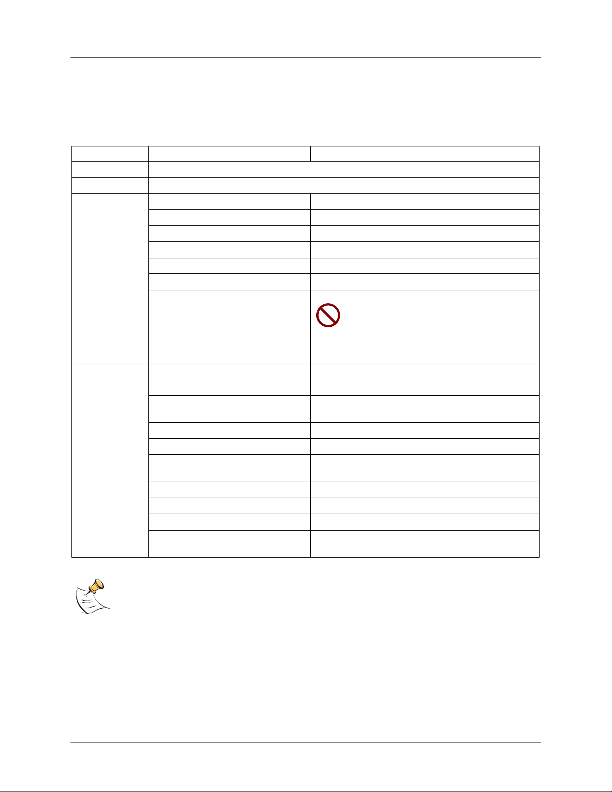
Table 1 lists the basic measurement equations for the Narrowband and the Wideband methods.
Table 1: Measurement Equations Definitions
Symbol Parameter Narrowband Equation Wideband Equation
V RMS Voltage V = √∑v(t)2 V = √∑v(t)2
I RMS Current I = S/V
P Active Power P = ∑ (i(t) * v(t)) P = ∑ (i(t) * v(t))
Q
S
PF Power Factor P/S P/S
PA Phase Angle ACOS (P/S) ACOS (P/S)
Reactive
Power
Apparent
Power
Q = ∑ (i(t) * v(t)shift 90º)
S = √(P2 + Q2) S = V * I
I = √∑i(t)2
Q = √(S2 – P2)
Both typ es of meas urement ou tputs ar e continuously available to th e user. To obtai n measurem ent
outputs, the serial UART interfac e between the 78M6612 and the host pr ocessor m ust be set up and is
described in the next section.
Rev. 1.0 5
Page 6

6612_OMU_S2+2_URT_V1_14 Firmware Description Document UG_6612_017
3 Serial Communication
The serial comm unication with th e 78M6 612 tak es place over a UART (UAR T0) interfac e. The d efaul t
settings for the UART of the 78M6612, as implemented i n this firm ware, are given below:
Bau d Rate: 38400bps
Data B its: 8
Parity: None
Stop Bits: 1
Flow Control: Xon/Xoff
The hos t’s s er ial interface port is required to i mp lement these s ettings on its UART. To verify
communication between the host and the 78M6612, the host must send a <CR> ( carriage return) to the
78M6612. Communication is verified when the 78M6612 returns a > (greater than sign) known as the
command prompt. An example is given below:
The host sends the following to the 78M6612:
<CR>
The 78M6612 sends the following back to the host:
>
Commands the host may send to the 78M6612 in order for the host to configur e the 78M6612 or to
receive the measurement data are given in the next sec tion .
6 Rev. 1.0
Page 7

UG_6612_ 017 6612_OMU_S2+2_URT_V1_14 Firmware Description Document
4 Command Line In ter f ace
Firmware 6612_OMU_S 2+2_URT_V1_14 implements an instruction set called the Command Line
Interface (CLI), which facilitates communication via U ART between the 78M6612 and the host proces sor.
The CLI provides a set of commands wh ich are u sed by the host to confi gur e and to obtain information
from t he 78M 6612.
4.1 Identification and Information Commands
The I command is used to identi fy the re visions of Demo Cod e and the c ontain ed CE code. The host
sends th e I command to th e 78M66 12 as follows:
>I<CR>
The 78M6612 will send back to the host the following:
TSC 78M6612 OMU S2+2 URT v1.14, Feb 09 2010(c)2009 Teridian S emiconductor Corp .
All Rights Reserved
CE6612_OMU_S2+2_A01_V1_4
>
4.2 R eset Comman ds
A soft r eset of the 78M66 12 can be performed by usin g the Z com mand . The soft r eset res tarts code
execution at ad dr 000 0 but does not al ter flash con tents. To issue a soft r eset to the 78M6612, the host
sends the following:
>Z<CR>
The W command acts like a h ar dware reset. The energy accu mu lators i n XRA M will retain their values.
Z Reset
Description: Allows the user to caus e soft resets.
Usage: Z Soft reset.
W Simu l ates watchdog reset.
Rev. 1.0 7
Page 8

6612_OMU_S2+2_URT_V1_14 Firmware Description Document UG_6612_017
4.3 MPU Data Acces s Comman d
The most p er tin ent is the MPU data acces s command. All the measurement calc ulations are stored i n the
MPU data addres ses of the 78M6612. The h ost requests measu r ement i nform ation u sing the MPU data
access command which is a right parenthesis
)
To request information, th e host sends the MPU data access command, the addres s (in hex) which is
requested, the format in which the dat a i s desired (Hex or Decimal) and a carr i age r eturn. Th e cont ents
of the addresses that would be request ed by the h ost are c ontai ned in Section 5.
4.3.1 Individual Address Read
The hos t can request the information in hex or decimal format. $ requests in formation in hex, and ?
requests information in decimal. When requesting information in decimal, the data is prec eded by a + or
a -. The exception is )AB? which returns a string (see the AB description).
An example of a command requesting the meas ured power in Watts from Outlet 1 (located at address
0x08) in decimal is as follows:
>)08?<CR>
An example of a command requesting the meas ured power in Watts from Outlet 1 (located at address
0x08) in hex is as follows:
>)08$<CR>
4.3.2 Consecutive Read
The hos t can request in formation from con secutive addresses by ad din g additional ? for decimal or
add i tion al $ for h ex.
An example of requests for the c ontents in decim al of ten c onsecuti ve addresses starting with 0x12 is:
>)12??????????<CR>
An example of requests for the c ontents in hex of ten consecutive addresses starting with 0x12 would be:
>)12$$$$$$$$$$<CR>
Note: The number of c haracters p er line is limited to no more than 60.
8 Rev. 1.0
Page 9

UG_6612_ 017 6612_OMU_S2+2_URT_V1_14 Firmware Description Document
4.3.3 Block Reads
The block read command can also be used to read consecutive registers: )saddr:eaddr? For decimal
format or )saddr:eaddr$ for hex fo r mat where saddr is the start address and eaddr is the final ad dress .
The following block r ead command r equest s the Outlet 1 wideband information contai ned i n Table 4 in
deci mal format:
>)20:3D?<CR>
4.3.4 Concatenated Reads
Multipl e commands c an al so be added on a single line. Reques ting information i n decimal from two
locati ons and the bloc k command from above are given below:
>)12?)15?)20:3D?<CR>
Note: The number of c haracters p er line is limited to no more than 60.
Rev. 1.0 9
Page 10

6612_OMU_S2+2_URT_V1_14 Firmware Description Document UG_6612_017
4.3.5 MPU/XDATA Access Commands
) MPU Data Access
Description: Allows user t o r ead from an d write to MPU data space.
Usage: ) {Starting MPU Data Address} {opt ion}…{option}<CR>
Command
Combinations:
Examples: )08$<CR> Reads data word 0x08 in hex format.
)saddr? <CR> Read the regist er in decimal.
)saddr?? <CR> Read two consecut i ve regi sters i n decimal.
)saddr???<CR> Read three consecut ive registers in decimal.
)saddr:eaddr?
Block read command in decimal format. Read
consecutive regi sters starting with starting
add r ess saddr and endi ng with addres s eaddr.
Results given in decimal.
)saddr$<CR> Read the register word in hex.
)saddr$$ <CR> Read two consecutive register words in hex.
)saddr$$$<CR> Read three consecutive register words in hex.
)saddr:eaddr$
Block read command in hex format. Read
consecutive regi sters starting with starting
add r ess saddr and endi ng with addres s eaddr.
Results given in hex.
)saddr=n<CR> Write the value n to add r ess saddr in hex format.
)saddr=n=m<CR> Write th e values n and m to two consecu tive
add r esses s tarti ng at saddr in hex format.
)saddr=+n<CR> Write the value n to addres s saddr in decimal
format.
)saddr=+n=+m<CR> Write the values n and m to two cons ecut ive
add r esses s tarti ng at saddr in decimal format.
)08$$<CR> Reads data words 0x08, 0x09 in hex format.
)08$$$<CR> Reads data words 0x08, 0x09, 0x0A in hex
format.
)28:4D$ Read Outlet 1 narrowband data words in hex.
)08?<CR> Reads data word 0x08 in decimal format.
)08??<CR> Reads data words 0x08, 0x09 in decimal format.
)08???<CR> Reads data words 0x08, 0x09, 0x0A in decimal
format.
)28:4D? Read Outlet 1 wideband data words in decimal.
)04=12345678<CR> Writes word @ 0x04 in hex format.
)04=12345678=9876ABCD<CR> Writes two words starting @ 0x04 in hex format.
)04=+123<CR> Writes word @ 0x04 in d ecim al format.
)04=+123=+334<CR> Writes two words starting @ 0x04 in decimal
format.
MPU or XDATA space is th e address r ange for the MPU X RA M ( 0x00 to 0x7F). Addresses
from 0x80 to FF wrap to 0x00 to 0x7F. The MPU reg isters differ in size, L SBs and format.
10 Rev. 1.0
Page 11

UG_6612_ 017 6612_OMU_S2+2_URT_V1_14 Firmware Description Document
4.4 Auxiliary Commands
4.4.1 Repeat Command
The repeat c ommand can be usefu l for monitoring m easuremen ts and i s efficient in demands from the
host.
If the host requ ests l ine freq uency, alarm st atus, Irms nb overc urrent event count, Vrms SAG event count,
Vrms overvoltage even t cou nt, voltage, power, an d acc umu l ated energy measurements for Outlet 1 with
the fol l owing c om mand string:
>)01????????<CR>
If the host then desires this same request without iss uing another command, the repeat command c an be
used:
>, (no carriage return needed for the repeat command)
The hos t onl y needs to sen d one charact er r ather than an entire string.
Auxiliary
Description: Various
Commands: , Typing a c om ma (“,”) repeats t he command
issued from the previous com mand l ine. This is
very helpful when exami ning the value at a
certai n address over time, such as the CE
DRAM addr ess for the temperature.
/ The slash (“/”) is useful to separ ate comments
from commands when sending m acro text fi les
via the serial interface. Al l characters i n a line
after the slash ar e ignored.
Rev. 1.0 11
Page 12

6612_OMU_S2+2_URT_V1_14 Firmware Description Document UG_6612_017
4.5 Calibration Commands
Using th e pr ecision sou r ce method, the u ser provides a precis i on voltage and precision cu r r ent l oad to
the device fo r calib r ati on. The 6612_OMU_S2+2_URT_V1_14 firmware provides commands to calibrate
the measurement units. For lin ear current sensors, su ch as current shunt, no phase calibration is
necessary.
There ar e two types of c alibration commands. The first type provides complet e calib r ation. The second
group, called atomic calib r ation commands, provides calibration for individual portions of the IC.
4.5.1 Complete Calibration Command (“Single Command Calibration”)
There ar e two calib r ation commands in this first grou p: CAL and CALW. Only one of these commands
is needed to calib r at e the System/Unit.
To use these c ommands, a precision voltage s ource and a precision current source are requi r ed
4.5.1.1 CAL Command
To use the CA L command, enter the following :
>CAL<CR>
The response is:
TCal OK
VCal OK
ICal 0 OK
>
The dev i ce would cal ibrate th e temperature (reads CE register 71, ent er s it into MPU register C0, and
saves to flash), cal ibrate th e voltage (adj ust s CAL VA and CAL VB r egisters and saves th em to flash),
and finally calibrate th e current (adju sts CAL IA regist er and saves to flash).
12 Rev. 1.0
Page 13

UG_6612_ 017 6612_OMU_S2+2_URT_V1_14 Firmware Description Document
4.5.1.2 CALW Command
To use the CALW comm and, enter the following:
>CALW<CR>
The response is:
TCal OK
VCal OK
WCal 0 OK
>
The dev i ce will calibrate t he temperatu r e, calibrate the voltage, and finally calibrate the po wer and s ave
all values t o flash.
The commands are summarized in the table below:
CALx Complete Calibration Commands
Description: Allows the user to Calibr ate the IC.
Usage: CAL Calibrates temperature, then voltage,
and finally current for Outlet 1.
CAL2 Calib r ates t emp er ature, then volt age,
and finally current for Outlet 2.
CAL3 Calib r ates t emp er ature, then volt age,
and finally current for both Outlet1 and
Outlet 2.
CALW Calib r ates t emp er ature, then volt age,
and finally power for Outlet 1.
CALW2 Calibrat es temperature, then voltage,
and finally power for Outlet 2.
CALW3 Calibrat es temperature, then voltage,
and finally power for both Outlet1 and
Outlet 2.
Rev. 1.0 13
Page 14

6612_OMU_S2+2_URT_V1_14 Firmware Description Document UG_6612_017
4.5.2 Atomic C alib ration C ommand s
The atomic c al ibration c ommands provide individual calibration of voltage, cur r ent, temperature, watts
and a sequence of these result s in providing fu l l calibration for the unit.
4.5.2.1 CLV Command
An example of an atomic c alibration comm and would be to calibrate volt age with t he CLV command. The
CLV command calibrates voltage to t he target value and tolerance and s aves the coefficien ts t o flash.
The CLV command example is gi ven below:
>CLV<CR>
The response is:
VCal OK
>
4.5.2.2 CLI Command
The us er can then calibrate the cu r r ent on Outlet 1 using the CLI1 command. The CLI 1 comm and
calibrates the current on Outlet 1 to the target valu e and tol er ance and saves the c oefficients to fl ash.
The CLI1 command example is given below:
>CLI1<CR>
The response is:
ICal 0 OK
>
4.5.2.3 CLP Command
The us er can calibrate for phase added by a current transformer by using the CLP command. The CLP
command calib r ates th e phase on Outlet 1 to the target valu e and toleran ce and saves the coefficient to
flash. An example of th e procedure is given below.
App l y a c ontrol led precision vol tage and current s ig nal at a set ph ase angle.
1. Enter target phase angle at ) C 3.
2. Enter phas e tolerance at )BF
3. Enter phas e calib r ation command.
>CLP<CR>
The response is
>PCal 1 OK
14 Rev. 1.0
Page 15

UG_6612_ 017 6612_OMU_S2+2_URT_V1_14 Firmware Description Document
4.5.2.4 CLT Command
The CLT command is us ed for the temperature calib r ation. Wi th this command, the content s of CE
register 71 are read and entered i nto MPU r egister C0 and the c ontents are saved to flash. Th e C LT
command exampl e i s given below:
>CLT<CR>
The response is:
TCal OK
>
A summary of the atomic calibration commands are gi ven in the table below:
CLxx Atomic Calibration
Commands
Description: Allows the user to Calib r ate individ ual sections of the IC.
Usage: CLV Calibrates volt age only.
CLI1 Calib r ate current on Outlet 1 only.
CLI2 Calib r ate current on Outlet 2 only.
CLI3 Calib r ate for current on both Outl et 1 and Outlet 2
only.
CLW1 Calibrate for power on Outlet 1 only.
CLW2 Calibrate for power on Outlet 2 only.
CLW3 Calibrate for power on both Outlet 1 and Outlet 2.
CLP Cal ibrate for phase on Outlet 1 only. Generally only
used when using cu r r ent transformers.
CLP2 Calibrate for phase on Outlet 2 only. Generally onl y
used when using cu r r ent transformers.
CLP3 Calibrate for phase on both Outlet 1 and Outlet 2.
Gener ally on ly used when using cu r r ent transformers.
CLT Calib r ate temperature only.
The commands that follow are mainly for advanced users and are included for reference only.
Rev. 1.0 15
Page 16

6612_OMU_S2+2_URT_V1_14 Firmware Description Document UG_6612_017
4.6 CE Data Acc es s Co m ma nds
The CE i s the main signal proces sing unit in the 78M6612. The user writes to the C E data space are
mainly for calibration purposes. For the advanc ed user, details of CE data access commands are
described. Th e commands similar to th e M PU access except that ] is u sed for the CE data access
command.
The hos t request s access to inform ation from the CE data space using the CE data access command
which is a right bracket:
]
To request information, th e host sends the CE data access c ommand, the address (in hex) which is
requested, the format in which the data is desired (hex or decimal) and a car r iage return. The cont ents of
the addr esses that would be r equested b y the host are contained in Section 5.
The hos t can request the information in hex or decimal format. $ requests information in hex and ?
requests information in decimal.
4.6.1 Single Register CE Access
An example of a command requesting the calibration constant for c urrent on Outlet 1 (located at address
0x08) in decimal is as follows:
>]08?<CR>
An example of a command requesting the calibration cons tant for current on Outlet 1 (located at ad dress
0x08) in hex is as follows:
>]08$<CR>
4.6.2 Consecutive CE Reads
The hos t can request in formation form con secutive addresses by ad din g additional ? for dec imal or
add i tion al $ for h ex.
An example of requests for the c ontents in decim al of ten c onsecutive addresses starting with 0x08 would be:
>]08??????????<CR>
An example of requests for the contents in hex of ten consecutive addresses starting with 0x08 would be:
>]08$$$$$$$$$$<CR>
Note: The number of c haracters p er line is limited to no more than 60.
16 Rev. 1.0
Page 17
UG_6612_ 017 6612_OMU_S2+2_URT_V1_14 Firmware Description Document
4.6.3 U Command
The U command is used for updat ing default values of the CE Data in flash . The desc r ipt i on is given i n
the CE control Command secti on.
Additional examples are pro vided i n the table that follows:
] CE Data Access
Description: Allows user t o r ead from an d write to CE data s pace.
Usage: ] {S tarting CE Data Add r ess}{option}…{option}<CR>
Command
Combinations:
Examples: ]40$<CR> Reads CE data word 0x40 in hex.
CE data space is the address range for the CE DRAM (0x1000 to 0x13FF). All CE data words
are in 4-byte (32-bit) format. The offset of 0x1000 does not have to be entered when using the
] command, thus typing ]A? will ac cess the 32-bit word located at the byte address 0x1000 + 4
* A = 0x1028.
]saddr?<CR> R ead 32-bit word in decimal.
]saddr??<CR> R ead two consecutive 32-bit words in decimal.
]saddr???<CR> R ead three consecutive 3 2-bit words in decimal.
]saddr$<CR> R ead 32-bit words in hex.
]saddr$$<CR> R ead two consecutive 32-bit words in hex.
]saddr$$$<CR> R ead three consecutive 32-bit words in hex.
]U<CR> Update default version of CE Data in
FLASH. Important: The CE must be
stopped (CE0) before issuing this
command! Also, remember to restart
by executing the CE1 command prior to
attempting measurements.
]40$$<CR> Reads CE data words 0x40 and 0x41 in hex.
]40$$$<CR> Reads CE dat a words 0x40, 0x41 and 0x42 in
hex.
]40?<CR> Reads CE data words 0x40 in decimal.
]40??<CR> Reads CE data words 0x40 and 0x41 in decimal.
]40???<CR> Reads CE dat a words 0x40, 0x41 and 0x42 in
decimal.
]7E=12345678<CR> Writes word at 0x7 E (hex format).
]7E=12345678=9876ABCD<CR> Wri tes two words s tarting at 0x7E (hex format).
]7E=+2255<CR> Write the value 2255 in decimal to l ocation 0x7E.
]7E=+2255=+456<CR> Write the value 2255 in decimal to l ocation 0x7 E
and the value 456 in decimal to location 0x7F.
Rev. 1.0 17
Page 18

6612_OMU_S2+2_URT_V1_14 Firmware Description Document UG_6612_017
4.7 CE Control Commands
The most p er tin ent command is the enable c om mand , CEn. It is mainly used to t urn the C E on or off
such th at the CE data contents can be updated in flash using the U comm and. The CE is n or mally on but
in order to update the CE data entry, the CE must first be turned off using the CE0.
4.7.1 CE Data Write
If the cal coefficient for the IA current inp ut is ch anged:
>]08=FFFFC9B0<CR>
4.7.2 Tu rn Off C E Command
For this value to b e the default value, th e U command is used. The CE must first be turned off using the
CE0 command:
>CE0<CR>
4.7.3 U Command
The U command is now is sued to change the default value set above as foll ows:
>]U<CR>
4.7.4 Turn On CE Command
The CE must then be turned on using the CE1 comm and:
>CE1<CR>
The default value for th e C AL IA coefficient is now changed in the CE Data space and is updated in
Flash.
The CE C ontrol Command s are highlighted in the table below:
C Compute Engine Control
Description: Allows the us er to enable an d configure the c om pute engine.
Usage: C {option} {argument}<CR>
Command
Combinations:
Examples: CE0<CR> Disables the CE.
CEn<CR> Compute Engine Enable (1 Enable,
0 Disable)
CTn<CR> Select input n for TMUX out put pin. Enter n i n hex
notation.
CREn<CR> RTM output cont r ol ( 1 Enable, 0 Disable)
CRSa.b.c.d<CR> Selects CE addresses for RTM output. (maximum
of four ).
CE1<CR> Enables th e C E.
CT1E<CR> Selects t he CE_ BUSY signal for the TMUX output
pin.
18 Rev. 1.0
Page 19

UG_6612_ 017 6612_OMU_S2+2_URT_V1_14 Firmware Description Document
4.8 I/O RAM (Configuration RAM) Command
The RI command is u sed for altering t he I/O RAM contents. This is usually not necess ary as t he FW
defaults thes e sett i ngs appropriately.
One case wher e the RI command could be used would be to change the accum ulation interval for energy
measurement s. The default ac cumulati on int er val is 1 second (999.75 ms). The accumulation i nterval i s
set by the following:
0.01666 * SUM_CYCLES[5:0] (in sec onds) where SUM_CYCLE[5:0] are regist er bit s in the I/O
RAM that can be between 1 5d and 63d (default i s 60d). SUM_CYCLES must never be set below
15 (0.250 seconds).
To reduce t he acc um ulation interval to 0. 5 seconds, enter t he following via the UART:
RI1=+30<CR>
En tering a U command will preserve th e new accu mu lation value acr oss p ower resets, by writing them to
flash.
R I/O RAM Control
Description: Allows the us er to read from and write to I/O RAM .
Usage: RI {option} {reg ister} … {opti on} <CR>
Command
Combinations:
Example: RI60$$$$<CR> Read all four RTM prob e reg isters.
Configurati on RA M space is the address rang e 0x2000 to 0x20FF. This RA M contains
registers used for configuring basic hardware and functional properties of the 78M6612
and is organized in bytes (8 bits). The 0x2000 offset is automatically added when the
command RI is typed.
RIx…<CR> Select I/O RAM location x (0x2000 offs et is
automatically ad ded) .
Rev. 1.0 19
Page 20

6612_OMU_S2+2_URT_V1_14 Firmware Description Document UG_6612_017
Minimum Temperature Alarm.
5 MPU Measurement Outputs
This s ection des cribes the measu r emen t outputs that can be obtained. Energy outputs are accumulated
numbers. The host accessing the measur ement i nformation from the 78M6612 mor e frequently will not
result in any update i n the information.
Table 2 list s the Narrowband outputs for Outlet 1.
Table 2: Outlet 1 MPU Outputs for Narrowband Method
Output
Delta
Temperature
Line
Frequency
Alarm Status 02
Location
(hex)
20 Rev. 1.0
LSB Comment Example
00 0.1 °C Temperature difference from 22 °C.
01 0.01 Hz Line Frequency.
Definiti o n for Status Register
Bit 0 –
Bit 1 – Maximum Temperature
Alarm.
Bit 2 – Minimum Frequency Alarm.
Bit 3 – Maximum Frequency Alarm.
Bit 4 - SAG Voltage Alarm.
Bit 5 – MINVA – under minimum
voltage on VA input.
Bit 6 – MAXVA – over maximum
voltage on VA input.
Bit 7 – MAXIA_NB – maximum
narrowband current exc eeded on
Outlet 1.
Bit 8 – MAXIA_WB – maximum
wideband current exceeded on
Outlet 1.
Bit 9 – PFA_NB negative –
Narrowband Power Factor Negative
Threshold Alarm for Outlet 1. Only
available is )F2 bit 2 is 1.
Bit 10 – PFA_NB positive –
Narrowband Power Factor Positive
Threshold Alarm for Outlet 1.
Bit 11 – PFA_WB negative -
Wideband Power Factor Negative
Threshold Alarm for Outlet 1. Only
available is )F2 bit 2 is 1.
Bit 12 – PFA_WB positive –
Wideband Power Factor Positive
Threshold Alarm for Outlet 1.
Bit 13 – MAXIB_NB – maximum
narrowband current exceeded on
Outlet 2.
Bit 14 – MAXIB_WB – maximum
wideband current exceeded on
Outlet 2.
If external temperature is 32 °C
)00?<CR>
Returns:
+10.0
If the line frequency is 60 Hz:
)01?<CR>
Returns:
+60.00
Alarms become “1” when
thresholds exceeded.
Note: Additional Status Alert is
Located at addr 0xBD
(see Table 8)
Note: When AC voltage input is
less than or equal to 10 V
• Only MINVA alarm is active.
• All measurements are
forced to 0 except power
factor, which is forced to 1.
Note: The frequency
measurement is forced to 0 as
long as the SAG voltage alarm
is active.
RMS
,
Page 21

UG_6612_ 017 6612_OMU_S2+2_URT_V1_14 Firmware Description Document
total
Output
Irms_nb A
Overcurrent
Event Count
Vrms Under
Voltage
Event Count
Vrms Over
Voltage
Event Count
Vrms A 06 mVrms Vrms voltage.
Location
(hex)
03 1
04 1
05 1
LSB Comment Example
Bit 15 – PFB_NB negative –
Narrowband Power Factor Negative
Threshold Alarm for Outlet 2. Only
available is )F2 bit 2 is 1.
Bit 16 – PFB_NB positive –
Narrowband Power Factor Positive
Threshold Alarm for Outlet 2.
Bit 17 – PFB_WB negative –
Wideband Power Factor Negative
Threshold Alarm for Outlet 2. Only
available is )F2 bit 2 is 1.
Bit 18– PFB_WB positive –
Wideband Power Factor Positive
Threshold Alarm for Outlet 2.
Bit 19 – MAXIT_WB – maximum
total wideband current exceeded on
both Outlet 1 and Outlet 2.
Bit 20 – MAXIT_NB – maximum
narrowband current exc eeded on
both Outlet 1 and Outlet 2.
Bit 21 – CREEP A Alert – Creep
Alert on Outlet 1.
Bit 22 – CREEP B Alert – Creep
Alert on Outlet 2.
Bit 23 – Line/Neutral Reversal
detected. Only available in non-
isolated mode (CESTATE, Bit 2=1)
Bit 24 – Reserved.
Bit 25 – Reserved.
Bit 26 – Unexpected Reset.
Bits 27-31 – Reserved.
If four narrowband over current
Counter increments on each edge
event.
Counter increments on each edge
event.
Counter increments on each edge
event.
events have occurred on Outlet 1:
)03?<CR>
Returns: +4
If four under voltage events have
occurred:
)04?<CR>
Returns: +4
If four over voltage events have
occurred:
)05?<CR>
Returns: +4
If the line voltage is 120 V
)06?<CR>
Returns:
+120.000
Rev. 1.0 21
Page 22

6612_OMU_S2+2_URT_V1_14 Firmware Description Document UG_6612_017
Location
Output
Watts A 07 mW
Wh A 08 mWh
Total Cost A 09 mUnits Outlet 1 cost of Wh A.
Irms_nb A 0A mArms
VARs_nb A 0B mW
VAs_nb A 0C mW
Power
Factor_nb A
Phase
Angle_nb A
Reserved 0F – Reserved
Vrms A Min 10 mV Minimum Vrms measured.
Vrms A Max 11 mV Maximum Vrms measured.
(hex)
0D –
0E –
LSB Comment Example
Outlet 1 active power
measurement (per second).
Outlet 1 active accumulated energy
measurement (per hour).
Outlet 1 narrowband rms current
measurement.
Outlet 1 narrowband reactive
power measurement (per second).
Outlet 1 narrowband apparent
power measurement (per second).
Outlet 1 narrowband power factor.
The output will be between -0.950
and 1.000. Positive power factor is
defined as current lagging voltage
(inductive). Negative power factor
is defined as voltage lagging
current (capacitive).
Outlet 1 narrowband phase angle.
The output will be between
180.000 and -180.000.
If 120 Watts are measured on
Outlet 1
)07?<CR>
Returns:
+120.000
If 120 Wh are measured on
Outlet 1
)08?<CR>
Returns:
+120.000
If the cost is 102.536 units on
Outlet 1
)09?<CR>
+102.536
If narrowband current measured on
Outlet 1 is 12 Amps
)0A?<CR>
Returns:
+12.000
If narrowband 120 VARs are
measured on Outlet 1
)0B?<CR>
Returns:
+120.000
If narrowband 120 VAs are
measured on Outlet 1
)0C?<CR>
Returns:
+120.000
If the narrowband power factor on
Outlet 1 is 0.95
)0D?<CR>
Returns:
+0.950
If the narrowband phase angle
measured on Outlet 1 is
60 degrees
)0E?<CR>
Returns:
+60.000
Reserved
If the minimum line voltage
measured was 105 V
)10<CR>
Returns:
+15.000
If the maximum line voltage
measured was 130 V
)11<CR>
Returns:
+130.000
22 Rev. 1.0
Page 23

UG_6612_ 017 6612_OMU_S2+2_URT_V1_14 Firmware Description Document
+10.000
Output
Watts A Min 12 mW
Watts A Max 13 mW
Irms_nb A
Min
Irms_nb A
Max
VARs_nb A
Min
VARs_nb A
Max
VAs_nb A
Min
VAs_nb A
Max
Power
Factor_nb A
Min
Power
Factor_nb A
Max
Phase
Angle_nb A
Min
Location
(hex)
14 mArms
15 mArms
16 mW
17 mWs
18 mW
19 mWs
1A –
1B –
1C –
LSB Comment Example
If the minimum power measured on
Minimum Outlet 1 active power
measured (per second).
Maximum Outlet 1 active power
measured (per second).
Outlet 1 minimum narrowband rms
current measured.
Outlet 1 maximum narrowband rms
current measured.
Outlet 1 minimum narrowband
reactive power measured (per
second).
Outlet 1 maximum narrowband
reactive power measured (per
second).
Outlet 1 minimum narrowband
apparent power measured (per
second).
Outlet 1 maximum narrowband
apparent power measured (per
second).
Outlet 1 minimum narrowband
power factor measured. Minimum
is defined as the most negative or
least positive number.
Outlet 1 maximum narrowband
power factor measured. Maximum
is defined as the most positive or
least negative number.
If the minimum narrowband phase
Outlet 1 minimum narrowband
phase angle measured.
Outlet 1 is 80 Watts
)12?<CR>
Returns:
+80.000
If the maximum power measured
on Outlet 1 is 200 Watts
)13?<CR>
Returns:
+200.000
If the smallest narrowband current
measured on Outlet 1 is 1 Amp
)14?<CR>
Returns:
+1.000
If the largest narrowband current
measured on Outlet 1 is 30 Amps
)15?<CR>
Returns:
+30.000
If the largest VARs measured on
Outlet 1 is 80 VARs
)16?<CR>
Returns:
+80.000
If the largest narrowband VARs
measured on Outlet 1 is 300VARs
)17?<CR>
Returns:
+300.000
If the smallest narrowband VAs
measured on Outlet 1 is 80 VARs
)18?<CR>
Returns:
+80.000
If the largest narrowband VAs
measured on Outlet 1 is 300VARs
)19?<CR>
Returns:
+300.000
If minimum narrowband power
factor measured on Outlet 1 is -0.6
)1A?<CR> Returns:
-0.600
If maximum narrowband power
factor measured on Outlet 1 is 0.9
)1B?<CR> Returns:
+0.900
angle measured on Outlet 1 is 10
degrees
)1C?<CR>
Returns:
Rev. 1.0 23
Page 24

6612_OMU_S2+2_URT_V1_14 Firmware Description Document UG_6612_017
Location
Outlet 2.
Output
Phase
Angle_nb A
Max
Reserved 1E – Reserved
Reserved 1F – Reserved
Location
(hex)
1D –
LSB Comment Example
If the maximum narrowband phase
angle measured on Outlet 1 is 70
Outlet 1 maximum narrowband
phase angle measured.
degrees
)1D?<CR>
Returns:
+70.000
Reserved
Reserved
Table 3 list s the wideband measurement outputs for Outlet 1.
Table 3: Outlet 1 MPU Outputs for Wideband Method
Output
Delta
Temperature
Line
Frequency
Alarm Status 22
(hex)
20 0.1 °C
21 0.01 Hz
LSB Comment Example
Temperature difference from 22° C.
Note: Duplicate of address 0x00
(see Table 2)
Line Frequency
Note: Duplicate of address 0x01
(see Table 2)
Definiti on for Status Register
Bit 0 – Minimum Temperature
Alarm.
Bit 1 – Maximum Temperature Alarm.
Bit 2 – Minimum Frequency Alarm.
Bit 3 – Maximum Frequency Alarm.
Bit 4 - SAG Voltage Alarm.
Bit 5 – MINVA – under minimum
voltage on VA input.
Bit 6 – MAXVA – over maximum
voltage on VA input.
Bit 7 – MAXIA_NB – maximum
narrowband current exc eeded on
Outlet 1.
Bit 8 – MAXIA_WB – maximum
wideband current exceeded on
Outlet 1.
Bit 9 – PFA_NB negative –
Narrowband Power Factor Negative
Threshold Alarm for Outlet 1. Only
available is )F2 bit 2 is 1.
Bit 10 – PFA_NB positive –
Narrowband Power Factor Positive
Threshold Alarm for Outlet 1.
Bit 11 – PFA_WB negative -
Wideband Power Factor Negative
Threshold Alarm for Outlet 1. Only
available is )F2 bit 2 is 1.
Bit 12 – PFA_WB positive –
Wideband Power Factor Positive
Threshold Alarm for Outlet 1.
Bit 13 – MAXIB_NB – maximum
narrowband current exc eeded on
If external temperature is 32 °C
)20?<CR>
Returns:
+10.0
If the line frequency is 60 Hz:
)21?<CR>
Returns:
+60.00
Alarms become “1” when
thresholds exceeded.
Note: Additional Status Alert is
Located at addr 0xBD (see Table 8)
Note: When AC voltage input is less
than or equal to 10 V
• Only MINVA alarm is active.
• All measurements are forced
to 0 except power factor,
which is forced to 1.
Note: The frequency measurement
is forced to 0 as long as the SAG
voltage alarm is active.
RMS
,
24 Rev. 1.0
Page 25

UG_6612_ 017 6612_OMU_S2+2_URT_V1_14 Firmware Description Document
Output
Irms_wb A
Overcurrent
Event Count
Vrms Under
Voltage
Event Count
Vrms Over
Voltage
Event Count
Vrms A 26 mV
Watts A 27 mW
Location
(hex)
23
24
25
LSB Comment Example
Bit 14 – MAXIB_WB – maximum
wideband current exceeded on
Outlet 2.
Bit 15 – PFB_NB negative –
Narrowband Power Factor Negative
Threshold Alarm for Outlet 2. Only
available is )F2 bit 2 is 1.
Bit 16 – PFB_NB positive
Narrowband Power Factor Positive
Threshold Alarm for Outlet 2.
Bit 17 – PFB_WB negative –
Wideband Power Factor Negative
Threshold Alarm for Outlet 2. Only
available is )F2 bit 2 is 1.
Bit 18– PFB_WB positive –
Wideband Power Factor Positive
Threshold Alarm for Outlet 2.
Bit 19 – MAXIT_WB – maximum
total wideband current exceeded on
both Outlet 1 and Outlet 2.
Bit 20 – MAXIT_NB – maximum
total narrowband current exceeded
on both Outlet 1 and Outlet 2.
Bit 21 – CREEP A Alert – Creep
Alert on Outlet 1.
Bit 22 – CREEP B Alert – Creep
Alert on Outlet 2.
Bit 23 – Line/Neutral Reversal
detected. Only available in non-
isolated mode (CEST ATE, Bit 2=1)
Bit 24 – Reserved.
Bit 25 – Reserved.
Bit 26 – Unexpected Reset.
Bits 27-31 – Reserved.
Note: Duplicate of address 0x02
(see Table 2)
Counter increments on each edge
event.
Counter increments on each edge
event.
Note: Duplicate of address 0x04
(see Table 2).
Counter increments on each edge
event.
Note: Duplicate of address 0x06
(see Table 2).
Vrms voltage
Note: Duplicate of address 0x06
(see Table 2).
Outlet 1 active power
measurement (per second).
Note: Duplicate of address 0x07
(see Table 2).
–
If four wideband over current
events have occurred on Outlet 1:
)23?<CR>
Returns: +4
If four under voltage events have
occurred:
If four over voltage events have
If the line voltage is 120 V
If 120 Watts are measured on
)24?<CR>
Returns: +4
occurred:
)25?<CR>
Returns: +4
)26?<CR>
Returns:
+120.000
Outlet 1
)27?<CR>
Returns:
+120.000
Rev. 1.0 25
Page 26

6612_OMU_S2+2_URT_V1_14 Firmware Description Document UG_6612_017
+12.000
Output
Wh A 28 mWh
Total Cost A 29 mUnits
Irms_wb A 2A mA
VARs_wb A 2B mW
VAs_wb A 2C mW
Power
Factor_wb A
Phase
Angle_wb A
Reserved 2F – Reserved
Vrms A Min 30 mV
Vrms A Max 31 mV
Watts A Min 32 mW
Location
(hex)
2D
2E –
LSB Comment Example
Outlet 1 active accumulated energy
measurement (per hour).
Note: Duplicate of address 0x08
(see Table 2).
Outlet 1 cost of Wh A.
Note: Duplicate of address 0x09
(see Table 2).
Outlet 1 wideband rms current
measurement.
Outlet 1 wideband reactive power
measurement (per second).
Outlet 1 wideband apparent power
measurement (per second).
Outlet 1 wideband power factor.
The output will be between -0.950
and 1.000. Positive power factor is
–
defined as current lagging voltage
(inductive). Negative power factor
is defined as voltage lagging
current (capacitive).
Outlet 1 wideband phase angle.
The output will be between
180.000 and -180.000.
Minimum Vrms measured
Note: Duplicate of address 0x10
(see Table 2).
Maximum Vrms measured
Note: Duplicate of address 0x11
(see Table 2).
Minimum Outlet 1 active power
measured (per second)
Note: Duplicate of address 0x12
(see Table 2)
If 120 Wh are measured on
Outlet 1
)28?<CR>
Returns:
+120.000
If the cost is 102.536 units on
Outlet 1
)29?<CR>
+102.536
If wideband current measured on
Outlet 1 is 12 Amps
)2A?<CR>
Returns:
If wideband 120 VARs are
measured on Outlet 1
)2B?<CR>
Returns:
+120.000
If wideband 120 VAs are measured
on Outlet 1
)2C?<CR>
Returns:
+120.000
If the wideband power factor on
Outlet 1 is 0.95
)2D?<CR>
Returns:
+0.950
If the wideband phase angle
measured on Outlet 1 is 60
degrees
)2E?<CR>
Returns:
+60.000
Reserved
If the minimum line voltage
measured was 105 V
)30<CR>
Returns:
+15.000
If the maximum line voltage
measured was 130 V
)31<CR>
Returns:
+130.000
If the minimum power measured on
Outlet 1 is 80 Watts
)32?<CR>
Returns:
+80.000
26 Rev. 1.0
Page 27

UG_6612_ 017 6612_OMU_S2+2_URT_V1_14 Firmware Description Document
Output
Watts A Max 33 mW
Irms_wb A
Min
Irms_wb A
Max
VARs_wb A
Min
VARs_wb A
Max
VAs_wb A
Min
VAs_wb A
Max
Power
Factor_wb A
Min
Power
Factor_wb A
Max
Phase
Angle_wb A
Min
Phase
Angle_wb A
Max
Reserved 3E-3F – Reserved
Location
(hex)
34 mArms
35 mArms
36 mW
37 mW
38 mW
39 mW
3A –
3B –
3C
3D –
LSB Comment Example
Maximum Outlet 1 active power
measured (per second)
Note: Duplicate of address 0x13
(see Table 2).
Outlet 1 minimum wideband rms
current measured.
Outlet 1 maximum wideband rms
current measured.
Outlet 1 minimum wideband
reactive power measured (per
second).
Outlet 1 maximum wideband
reactive power measured (per
second).
Outlet 1 minimum wideband
apparent power measured (per
second).
Outlet 1 maximum wideband
apparent power measured (per
second).
Outlet 1 minimum wideband power
factor measured. Minimum is
defined as the most negative or
least positive number.
Outlet 1 maximum wideband power
factor measured. Max imu m is
defined as the most positive or
least negative number.
–
Outlet 1 minimum wideband phase
angle measured.
Outlet 1 maximum wideband phase
angle measured.
If the maximum power measured
on Outlet 1 is 200 Watts
)33?<CR>
Returns:
+200.000
If the smallest wideband current
measured on Outlet 1 is 1 Amp
)34?<CR>
Returns:
+1.000
If the largest wideband current
measured on Outlet 1 is 30 Amps
)35?<CR>
Returns:
+30.000
If the largest VARs measured on
Outlet 1 is 80 VARs
)36?<CR>
Returns:
+80.000
If the largest VARs measured on
Outlet 1 is 300 VARs
)37?<CR>
Returns:
+300.000
If the smallest VAs measured on
Outlet 1 is 80 VARs
)38?<CR>
Returns:
+80.000
If the largest VAs measured on
Outlet 1 is 300 VARs
)39?<CR>
Returns:
+300.000
If minimum wideband power factor
measured on Outlet 1 is –0.6
)3A?<CR> Returns:
-0.600
If maximum wideband power factor
measured on Outlet 1 is 0.9
)3B?<CR> Returns:
+0.900
If the minimum wideband phase
angle measured on Outlet 1 is 10
degrees
)3C?<CR>
Returns:
+10.000
If the maximum wideband phase
angle measured on Outlet 1 is 70
degrees
)3D?<CR>
Returns:
+70.000
Reserved
Rev. 1.0 27
Page 28

6612_OMU_S2+2_URT_V1_14 Firmware Description Document UG_6612_017
Temperature difference from 22° C.
Table 4 list s the narrowban d measurem ent outputs for Outlet 2.
Table 4: Outlet 2 MPU Outputs for Narrowband Method
Output
Delta
Temperature
Line
Frequency
Alarm Status 42
Location
(hex)
40 0.1 °C
41 0.01 Hz
LSB Comment Example
Note: Duplicate of address 0x00
(see Table 2).
Line Frequency
Note: Duplicate of address 0x01
(see Table 2).
Definition for Status Register
Bit 0 – Minimum Temperature
Alarm.
Bit 1 – Maximum Temperature
Alarm.
Bit 2 – Minimum Frequency Alarm.
Bit 3 – Maximum Frequency Alarm.
Bit 4 – SAG Voltage Alarm.
Bit 5 – MINVA – under minimum
voltage on VA input.
Bit 6 – MAXVA – over maximum
voltage on VA input.
Bit 7 – MAXIA_NB – maximum
narrowband current exc eeded on
Outlet 1.
Bit 8 – MAXIA_WB – maximum
wideband current exceeded on
Outlet 1.
Bit 9 – PFA_NB negative –
Narrowband Power Factor
Negative Threshold Alarm for
Outlet 1. Only available is )F2 bit 2
is 1.
Bit 10 – PFA_NB positive –
Narrowband Power Factor Positive
Threshold Alarm for Outlet 1.
Bit 11 – PFA_WB negative –
Wideband Power Factor Negative
Threshold Alarm for Outlet 1. Only
available is )F2 bit 2 is 1.
Bit 12 – PFA_WB positive –
Wideband Power Factor Positive
Threshold Alarm for Outlet 1.
Bit 13 – MAXIB_NB – maximum
narrowband current exc eeded on
Outlet 2.
Bit 14 – MAXIB_WB – maximum
wideband current exceeded on
Outlet 2.
Bit 15 – PFB_NB negative –
Narrowband Power Factor
Negative Threshold Alarm for
Outlet 2. Only available is )F2 bit 2
is 1.
If external temperature is 32 °C
)40?<CR>
Returns:
+10.0
If the line frequency is 60 Hz:
)41?<CR>
Returns:
+60.00
Alarms become “1” when
thresholds exceeded.
Note: Additional Status Alert is
Located at addr 0xBD (see Table
8).
Note: When AC voltage input is
less than or equal to 10 V
• Only MINVA alarm is active.
• All measurements are
forced to 0 except power
factor, which is forced to 1.
Note: The frequency measurement
is forced to 0 as long as the SAG
voltage alarm is active.
RMS
,
28 Rev. 1.0
Page 29

UG_6612_ 017 6612_OMU_S2+2_URT_V1_14 Firmware Description Document
Output
Irms_nb B
Overcurrent
Event Count
Vrms Under
Voltage
Event Count
Vrms Over
Voltage
Event Count
Vrms A 46 mV
Watts B 47 mW
Wh B 48 mWh
Location
(hex)
43
44
45
LSB Comment Example
Bit 16 – PFB_NB positive –
Narrowband Power Factor Positive
Threshold Alarm for Outlet 2.
Bit 17 – PFB_WB negative –
Wideband Power Factor Negative
Threshold Alarm for Outlet 2. Only
available is )F2 bit 2 is 1.
Bit 18– PFB_WB positive –
Wideband Power Factor Positive
Threshold Alarm for Outlet 2.
Bit 19 – MAXIT_WB – maximum
total wideband current exceeded on
both Outlet 1 and Outlet 2.
Bit 20 – MAXIT_NB – maximum
total narrowband current exceeded
on both Outlet 1 and Outlet 2.
Bit 21 – CREEP A Alert – Creep
Alert on Outlet 1.
Bit 22 – CREEP B Alert – Creep
Alert on Outlet 2.
Bit 23 – Line/Neutral Reversal
detected. Only available in non-
isolated mode (CEST ATE, Bit 2=1)
Bit 24 – Reserved.
Bit 25 – Reserved.
Bit 26 – Unexpected Reset.
Bits 27-31 – Reserved.
Note: Duplicate of address 0x02
Counter increments on each edge
Counter increments on each edge
Note: Duplicate of address 0x04
Counter increments on each edge
Note: Duplicate of address 0x06
Note: Duplicate of address 0x06
Outlet 2 active power measurement
Outlet 2 active accumulated energy
measurement (per hour).
(see Table 2).
event.
event.
(see Table 2).
event.
(see Table 2).
Vrms voltage
(see Table 2).
(per second).
If four narrowband over current
events have occurred on Outlet 2:
)43?<CR>
Returns: +4
If four under voltage events have
occurred:
)44?<CR>
Returns: +4
If 4 over voltage events have
occurred:
)45?<CR>
Returns: +4
If the line voltage is 120 V
)46?<CR>
Returns:
+120.000
If 120 Watts are measured on
Outlet 2
)47?<CR>
Returns:
+120.000
If 120 Wh are measured on
Outlet 2
)48?<CR>
Returns:
+120.000
Rev. 1.0 29
Page 30

6612_OMU_S2+2_URT_V1_14 Firmware Description Document UG_6612_017
Output
Total Cost B 49 mUnits Outlet 2 cost of Wh B .
Irms_nb B 4A mArms
VARs_nb B 4B mW
VAs_nb B 4C mW
Power
Factor_nb B
Phase
Angle_nb B
Reserved 4F – Reserved
Vrms A Min 50 mV
Vrms A Max 51 mV
Watts B Min 52 mW
Watts B Max 53 mW
Location
(hex)
4D –
4E –
LSB Comment Example
If the total cost is 102.536 units on
Outlet 2
)49?<CR>
+102.536
If narrowband current measured on
Outlet 2 narrowband rms current
measurement.
Outlet 2 narrowband reactive power
measurement (per second).
Outlet 2 narrowband apparent
power measurement (per second).
Outlet 2 narrowband power factor.
The output will be between -0.950
and 1.000. Positive power factor is
defined as current lagging voltage
(inductive). Negative power factor
is defined as voltage lagging
current (capacitive).
Outlet 2 narrowband phase angle.
The output will be between 180.000
and
-180.000.
Minimum Vrms measured
Note: Duplicate of address 0x10
(see Table 2).
Maximum Vrms measured
Note: Duplicate of address 0x11
(see Table 2).
If the minimum power measured on
Minimum Outlet 2 active power
measured (per second).
Maximum Outlet 2 active power
measured (per second).
Outlet 2 is 12 Amps
)4A?<CR>
Returns:
+12.000
If narrowband 120 VARs are
measured on Outlet 2
)4B?<CR>
Returns:
+120.000
If narrowband 120 VAs are
measured on Outlet 2
)4C?<CR>
Returns:
+120.000
If the narrowband power factor on
Outlet 2 is 0.95
)4D?<CR>
Returns:
+0.950
If the narrowband phase angle
measured on Outlet 2 is 60
degrees
)4E?<CR>
Returns:
+60.000
Reserved
If the minimum line voltage
measured was 105 V
)50<CR>
Returns:
+15.000
If the maximum line voltage
measured was 130 V
)51<CR>
Returns:
+130.000
Outlet 2 is 80 Watts
)52?<CR>
Returns:
+80.000
If the maximum power measured
on Outlet 2 is 200 Watts
)53?<CR>
Returns:
+200.000
30 Rev. 1.0
Page 31

UG_6612_ 017 6612_OMU_S2+2_URT_V1_14 Firmware Description Document
–
Output
Irms_nb B
Min
Irms_nb B
Max
VARs_nb B
Min
VARs_nb B
Max
VAs_nb B
Min
VAs_nb B
Max
Power
Factor_nb B
Min
Power
Factor_nb B
Max
Phase
Angle_nb B
Min
Phase
Angle_nb B
Max
Reserved 5E – Reserved
Reserved 5F
Location
(hex)
54 mArms
55 mArms
56 mW
57 mW
58 mW
59 mW
5A –
5B
5C
5D –
LSB Comment Example
If the smallest narrowband current
Outlet 2 minimum narrowband rms
current measured.
Outlet 2 maximum narrowband rms
current measured.
Outlet 2 minimum narrowband
reactive power measured (per
second).
Outlet 2 maximum narrowband
reactive power measured (per
second).
Outlet 2 minimum narrowband
apparent power measured (per
second)
Outlet 2 maximum narrowband
apparent power measured (per
second).
Outlet 2 minimum narrowband
power factor measured. Minimum
is defined as the most negative or
least positive number.
Outlet 2 maximum narrowband
–
–
power factor measured. Maximum
is defined as the most positive or
least negative number.
Outlet 2 minimum narrowband
phase angle measured.
Outlet 2 maximum narrowband
phase angle measured.
Reserved
measured on Outlet 2 is 1 Amp
)54?<CR>
Returns:
+1.000
If the largest narrowband current
measured on Outlet 2 is 30 Amps
)55?<CR>
Returns:
+30.000
If the largest VARs measured on
Outlet 2 is 80 VARs
)56?<CR>
Returns:
+80.000
If the largest narrowband VARs
measured on Outlet 2 is
300 VARs
)57?<CR>
Returns:
+300.000
If the smallest narrowband VAs
measured on Outlet 2 is 80 VARs
)58?<CR>
Returns:
+80.000
If the largest narrowband VAs
measured on Outlet 2 is
300 VARs
)59?<CR>
Returns:
+300.000
If minimum narrowband power
factor measured on Outlet 2 is
-0.6
)5A?<CR> Returns:
-0.600
If maximum narrowband power
factor measured on Outlet 2 is 0.9
)5B?<CR> Returns:
+0.900
If the minimum narrowband phase
angle measured on Outlet 2 is 10
degrees
)5C?<CR>
Returns:
+10.000
If the maximum narrowband phase
angle measured on Outlet 2 is 70
degrees
)5D?<CR>
Returns:
+70.000
Reserved
Reserved
Rev. 1.0 31
Page 32

6612_OMU_S2+2_URT_V1_14 Firmware Description Document UG_6612_017
Temperature difference from 22° C.
Table 5 lists the wideband measurem ent output s for Outlet 2.
Table 5: Outlet 2 MPU Outputs for Wideband Method
Output
Delta
Temperature
Line
Frequency
Alarm Status 62
Location
(hex)
60 0.1 °C
61 0.01 Hz
LSB Comment Example
Note: Duplicate of address 0x00
Table 2).
(see
Line Frequency
Note: Duplicate of address 0x01
(see Table 2).
Definiti o n for Status Register
Bit 0 – Minimum Temperature
Alarm.
Bit 1 – Maximum Temperature
Alarm.
Bit 2 – Minimum Frequency Alarm.
Bit 3 – Maximum Frequency Alarm.
Bit 4 - SAG Voltage Alarm.
Bit 5 – MINVA – under minimum
voltage on VA input.
Bit 6 – MAXVA – over maximum
voltage on VA input.
Bit 7 – MAXIA_NB – maximum
narrowband current exc eeded on
Outlet 1.
Bit 8 – MAXIA_WB – maximum
wideband current exceeded on
Outlet 1.
Bit 9 – PFA_NB negative –
Narrowband Power Factor Negative
Threshold Alarm for Outlet 1. Only
available is )F2 bit 2 is 1.
Bit 10 – PFA_NB positive –
Narrowband Power Factor Positive
Threshold Alarm for Outlet 1.
Bit 11 – PFA_WB negative -
Wideband Power Factor Negative
Threshold Alarm for Outlet 1. Only
available is )F2 bit 2 is 1.
Bit 12 – PFA_WB positive –
Wideband Power Factor Positive
Threshold Alarm for Outlet 1.
Bit 13 – MAXIB_NB – maximum
narrowband current exc eeded on
Outlet 2.
Bit 14 – MAXIB_WB – maximum
wideband current exceeded on
Outlet 2.
Bit 15 – PFB_NB negative –
Narrowband Power Factor Negative
Threshold Alarm for Outlet 2. Only
available is )F2 bit 2 is 1.
Bit 16 – PFB_NB positive –
Narrowband Power Factor Positive
Threshold Alarm for Outlet 2.
If external temperature is 32 °C
)60?<CR>
Returns:
+10.0
If the line frequency is 60 Hz:
)61?<CR>
Returns:
+60.00
Alarms become “1” when
thresholds exceeded.
Note: Additional Status Alert is
Located at addr 0xBD
(see Table 8).
Note: When AC voltage input is
less than or equal to 10 V
• Only MINVA alarm is
active.
• All measurements are
forced to 0 except power
factor, which is forced to 1.
Note: The frequency
measurement is forced to 0 as
long as the SAG voltage alarm is
active.
RMS
,
32 Rev. 1.0
Page 33

UG_6612_ 017 6612_OMU_S2+2_URT_V1_14 Firmware Description Document
Output
Irms_wb B
Overcurrent
Event Count
Vrms Under
Voltage
Event Count
Vrms Over
Voltage
Event Count
Vrms A 66 mV
Watts B 67 mW
Wh B 68 mWh
Total Cost B 69 mUnits
Location
(hex)
63
64
65
LSB Comment Example
Bit 17 – PFB_WB negative –
Wideband Power Factor Negative
Threshold Alarm for Outlet 2. Only
available is )F2 bit 2 is 1.
Bit 18– PFB_WB positive –
Wideband Power Factor Positive
Threshold Alarm for Outlet 2.
Bit 19 – MAXIT_WB – maximum
total wideband current exceeded on
both Outlet 1 and Outlet 2.
Bit 20 – MAXIT_NB – maximum
total narrowband current exceeded
on both Outlet 1 and Outlet 2.
Bit 21 – CREEP A Alert – Creep
Alert on Outlet 1.
Bit 22 – CREEP B Alert – Creep
Alert on Outlet 2.
Bit 23 – Line/Neutral Reversal
detected. Only available in non-
isolated mode (CEST ATE, Bit 2=1)
Bit 24 – Reserved.
Bit 25 – Reserved.
Bit 26 – Unexpected Reset.
Bits 27-31 – Reserved.
Note: Duplicate of address 0x02
Counter increments on each edge
Counter increments on each edge
Note: Duplicate of address 0x04
Counter increments on each edge
Note: Duplicate of address 0x06
Note: Duplicate of address 0x06
Outlet 2 active power
measurement (per second)
Note: Duplicate of address 0x47
Outlet 2 active accumulated energy
measurement (per hour)
Note: Duplicate of address 0x48
Outlet 2 cost of Wh B
Note: Duplicate of address 0x49
(see Table 2)
event.
event.
(see Table 2).
event.
(see Table 2).
Vrms voltage
(see Table 2).
(see Table 4).
(see Table 4).
(see Table 4).
If four wideband over current
events have occurred on Outlet 2:
)63?<CR>
Returns: +4
If 4 under voltage events have
occurred:
)64?<CR>
Returns: +4
If 4 over voltage events have
occurred:
)65?<CR>
Returns: +4
If the line voltage is 120 V
)66?<CR>
Returns:
+120.000
If 120 Watts are measured on
Outlet 2
)67?<CR>
Returns:
+120.000
If 120 Wh are measured on
Outlet 2
)68?<CR>
Returns:
+120.000
If the total cost is 102.536 units on
Outlet 2
)69?<CR>
+102.536
Rev. 1.0 33
Page 34

6612_OMU_S2+2_URT_V1_14 Firmware Description Document UG_6612_017
Output
Irms_wb B 6A mArms
VARs_wb B 6B mW
VAs_wb B 6C mW
Power
Factor_wb B
Phase
Angle_wb B
Reserved 6F – Reserved
Vrms A Min 70 mV
Vrms A Max 71 mV
Watts B Min 72 mW
Watts B Max 73 mW
Irms_wb B
Min
Location
(hex)
6D
6E mDegrees
74 mArms
LSB Comment Example
If wideband current measured on
Outlet 2 wideband rms current
measurement.
Outlet 2 wideband reactive power
measurement (per second).
Outlet 2 wideband apparent power
measurement (per second).
Outlet 2 wideband power factor.
The output will be between -0.950
and 1.000. Positive power factor is
–
defined as current lagging voltage
(inductive). Negative power factor
is defined as voltage lagging
current (capacitive).
Outlet 2 wideband phase angle.
The output will be between
180.000 and -180.000.
Minimum Vrms measured
Note: Duplicate of address 0x10
(see Table 2).
Maximum Vrms measured
Note: Duplicate of address 0x11
(see Table 2).
Minimum Outlet 2 active power
measured (per second)
Note: Duplicate of address 0x52
(see Table 4).
Maximum Outlet 2 active power
measured (per second)
Note: Duplicate of address 0x53
(see Table 4).
Outlet 2 minimum wideband rms
current measured.
Outlet 2 is 12 Amps
)6A?<CR>
Returns:
+12.000
If wideband 120 VARs are
measured on Outlet 2
)6B?<CR>
Returns:
+120.000
If wideband 120 VAs are
measured on Outlet 2
)6C?<CR>
Returns:
+120.000
If the wideband power factor on
Outlet 2 is 0.95
)6D?<CR>
Returns:
+0.950
If the wideband phase angle
measured on Outlet 2 is
60 degrees
)6E?<CR>
Returns:
+60.000
Reserved
If the minimum line voltage
measured was 105 V
)70<CR>
Returns:
+15.000
If the maximum line voltage
measured was 130 V
)71<CR>
Returns:
+130.000
If the minimum power measured
on Outlet 2 is 80 Watts
)72?<CR>
Returns:
+80.000
If the maximum power measured
on Outlet 2 is 200 Watts
)73?<CR>
Returns:
+200.000
If the smallest wideband current
measured on Outlet 2 is 1 Amp
)74?<CR>
Returns:
+1.000
34 Rev. 1.0
Page 35

UG_6612_ 017 6612_OMU_S2+2_URT_V1_14 Firmware Description Document
Output
Irms_wb B
Max
VARs_wb B
Min
VARs_wb B
Max
VAs_wb B
Min
VAs_wb B
Max
Power
Factor_wb B
Min
Power
Factor_wb B
Max
Phase
Angle_wb B
Min
Phase
Angle_wb B
Max
Reserved 7E
Reserved 7F – Reserved
Location
(hex)
75 mArms
76 mW
77 mW
78 mW
79 mW
7A
7B –
7C mDegrees
7D mDegree
LSB Comment Example
If the largest wideband current
Outlet 2 maximum wideband rms
current measured.
Outlet 2 minimum wideband
reactive power measured (per
second).
Outlet 2 maximum wideband
reactive power measured (per
second).
Outlet 2 minimum wideband
apparent power measured (per
second).
Outlet 2 maximum wideband
apparent power measured (per
second).
Outlet 2 minimum wideband power
factor measured. Minimum is
defined as the most negative or
least positive number.
Outlet 2 maximum wideband power
factor measured. Max imu m is
defined as the most positive or
least negative number.
Outlet 2 minimum wideband phase
angle measured.
Outlet 2 maximum wideband phase
angle measured.
–
Reserved
measured on Outlet 2 is 30 Amps
)75?<CR>
Returns:
+30.000
If the largest VARs measured on
Outlet 2 is 80 VARs
)76?<CR>
Returns:
+80.000
If the largest VARs measured on
Outlet 2 is 300 VARs
)77?<CR>
Returns:
+300.000
If the smallest VAs measured on
Outlet 2 is 80 VARs
)78?<CR>
Returns:
+80.000
If the largest VAs measured on
Outlet 2 is 300 VARs
)79?<CR>
Returns:
+300.000
If minimum wideband power factor
measured on Outlet 2 is –0.6
)7A?<CR> Returns:
-0.600
If maximum wideband power
factor measured on Outlet 2 is 0.9
)7B?<CR> Returns:
+0.900
If the minimum wideband phase
angle measured on Outlet 2 is
10 degrees
)7C?<CR>
Returns:
+10.000
If the maximum wideband phase
angle measured on Outlet 2 is
70 degrees
)7D?<CR>
Returns:
+70.000
Reserved
Reserved
Rev. 1.0 35
Page 36

6612_OMU_S2+2_URT_V1_14 Firmware Description Document UG_6612_017
+120.000
Table 6 list s the narrowban d measurem ent outputs for both outlets combined (Outlet 1 + Outlet 2).
Table 6: Combined Outlets MPU Outputs for Narrowband Method
Output
Watts T 80 mW
Wh T 81 mWh
Total Cost T 82 mUnits Total Cost of Wh for both outlets.
Irms_nb T 83 mArms
VARs_nb T 84 mW
VAs_nb T 85 mW
Irms_nb T
Overcurrent
Event
Count
Reserved 87
Watts T Min 88 mW
Watts T
Max
Irms_nb T
Min
Location
(hex)
86
89 mW
8A mArms
LSB Comment Example
Active power measurement (per
second) on both outlets.
Active acc um ulated energy
measurement (per hour) on both
outlets.
Combined outlet narrowband rms
current measurement.
Combined outlet narrowband
reactive power measurement (per
second).
Combined outlet narrowband
apparent power measurement (per
second).
Counter increments on each edge
event.
–
Minimum combined outlet active
power measured (per second).
Maximum combined active power
Minimum combined outlet
narrowband rms current measured.
Reserved
measured (per second).
If 120 Watts are measured on both
outlets
)80?<CR>
Returns:
If 120 Wh are measured on
Outlet 2
)81?<CR>
Returns:
+120.000
If the total cost is 102.536 units on
both outlets
)82?<CR>
+102.536
If narrowband current measured on
both outlets is 12 Amps
)83?<CR>
Returns:
+12.000
If narrowband 120 VARs are
measured on both outlets
)84?<CR>
Returns:
+120.000
If narrowband 120 VAs are
measured on both outlets
)85?<CR>
Returns:
+120.000
If four narrowband over current
events have occurred on Outlet 1
and Outlet 2:
)86?<CR>
Returns:
+4
Reserved
If the minimum power measured on
both outlets is 80 Watts
)88?<CR>
Returns:
+80.000
If the maximum power measured
on both outlets is 200 Watts
)89?<CR>
Returns:
+200.000
If the smallest narrowband current
measured on both outlets is 1 Amp
)8A?<CR>
Returns:
+1.000
36 Rev. 1.0
Page 37

UG_6612_ 017 6612_OMU_S2+2_URT_V1_14 Firmware Description Document
Output
Irms_nb T
Max
VARs_nb T
Min
VARs_nb T
Max
VAs_nb T
Min
VAs_nb T
Max
Location
(hex)
8B mArms
8C mW
8D mW
8E mW
8F mW
LSB Comment Example
If the largest narrowband current
measured on both outlets is 30
Maximum co mbined outlet
narrowband rms current measured.
Minimum combined outlet
narrowband reactive power
measured (per second).
Maximum combined outlet
narrowband reactive power
measured (per second).
Minimum combined outlet
narrowband apparent power
measured (per second).
Maximum co mbined outlet
narrowband apparent power
measured (per second).
If the largest narrowband VARs
measured on both outlets is 80
If the largest narrowband VARs
measured on both outlets is 300
If the smallest narrowband VAs
measured on both outlets is 80
If the largest narrowband VAs
measured on both outlets is 300
Amps
)8B?<CR>
Returns:
+30.000
VARs
)8C?<CR>
Returns:
+80.000
VARs
)8D?<CR>
Returns:
+300.000
VARs
)8E?<CR>
Returns:
+80.000
VARs
)8F?<CR>
Returns:
+300.000
Rev. 1.0 37
Page 38

6612_OMU_S2+2_URT_V1_14 Firmware Description Document UG_6612_017
+120.000
Table 7 lists the wideband measurement outputs for both outlets combined (O utl e t 1 + Outl e t 2).
Table 7: Combined Outlets M PU Outputs for Wideband Method
Output
Watts T 90 mW
Wh T 91 mWh
Total Cost T 92 mUnits
Irms_wb T 93 mArms
VARs_wb T 94 mW
VAs_wb T 95 mW
Irms_wb T
Overcurrent
Event
Count
Reserved 97
Watts T Min 98 mW
Watts T
Max
Irms_wb T
Min
Location
(hex)
96
99 mW
9A mArms
LSB Comment Example
–
Active power measurement (per
second) on both outlets.
Note: Duplicate of address 0x80
(see Table 6).
Active accumulated energy
measurement (per hour) on both
outlets.
Note: Duplicate of address 0x81
(see Table 6).
Total Cost of Wh for both outlets.
Note: Duplicate of address 0x82
(see Table 6).
Combined outlet wideband rms
current measurement.
Combined outlet wideband reactive
power measurement (per second).
Combined outlet wideband
apparent power measurement (per
second).
Counter increments on each edge
event.
Reserved
Minimum combined outlet active
power measured (per second)
Note: Duplicate of address 0x88
(see Table 6).
Maximum combined outlet active
power measured (per second)
Note: Duplicate of address 0x89
(see Table 6).
Minimum combined outlet
wideband rms current measured.
If 120 Watts are measured on both
outlets
)90?<CR>
Returns:
If 120 Wh are measured on
Outlet 2
)91?<CR>
Returns:
+120.000
If the total cost is 102.536 units on
both outlets
)92?<CR>
+102.536
If wideband current measured on
both outlets is 12 Amps
)93?<CR>
Returns:
+12.000
If wideband 120 VARs are
measured on both outlets
)94?<CR>
Returns:
+120.000
If wideband 120 VAs are measured
on both outlets
)95?<CR>
Returns:
+120.000
If four wideband over current
events have occurred on Outlet 1
and Outlet 2:
)96?<CR>
Returns:
+4
Reserved
If the minimum power measured on
both outlets is 80 Watts
)98?<CR>
Returns:
+80.000
If the maximum power measured
on both outlets is 200 Watts
)99?<CR>
Returns:
+200.000
If the smallest wideband current
measured on both outlets is 1 Amp
)9A?<CR>
Returns:
+1.000
38 Rev. 1.0
Page 39

UG_6612_ 017 6612_OMU_S2+2_URT_V1_14 Firmware Description Document
Output
Irms_wb T
Max
VARs_wb T
Min
VARs_wb T
Max
VAs_wb T
Min
VAs_wb T
Max
Location
(hex)
9B mArms
9C mW
9D mW
9E mW
9F mW
LSB Comment Example
If the largest wideband current
measured on both outlets is 30
Maximum co mbined outlet
wideband rms current measured.
Minimum combined outlet
wideband reactive power
measured (per second).
Maximum co mbined outlet
wideband reactive power
measured (per second).
Minimum combined outlet
wideband apparent power
measured (per second).
Maximum co mbined outlet
wideband apparent power
measured (per second).
If the largest VARs measured on
both outlets is 80 VARs
If the largest VARs measured on
both outlets is 300 VARs
If the smallest VAs measured on
both outlets is 80 VARs
If the largest VAs measured on
both outlets is 300 VARs
Amps
)9B?<CR>
Returns:
+30.000
)9C?<CR>
Returns:
+80.000
)9D?<CR>
Returns:
+300.000
)9E?<CR>
Returns:
+80.000
)9F?<CR>
Returns:
+300.000
Rev. 1.0 39
Page 40

6612_OMU_S2+2_URT_V1_14 Firmware Description Document UG_6612_017
6 Configuration Parameter Entry
6.1 MPU Param eters
Table 8 l i sts the MPU parameters configurable by Fir mware 6612_OMU _S2+2_URT_V1_14.
Table 8: MPU Par ameters
MPU
Parameter
VMAX A A0 mVrms +471.500
Starting IA A1 mArms +0.007
IMAX A A2 mArms +52.000
Starting IB A3 mArms +0.007
IMAX B A4 mArms +52.000
Unused A5 – – Unused
Location
(hex)
LSB Default Comment Example
External rms voltage
corresponding to 250 mVpk at the
VA input of the 78M6612. It must
be set high enough to account for
overvoltages. Usually set to
471.500 V (471.500d).
Minimum current value to be
measured on the IA input.
Currents below this value will be
ignored. Also known as CREEP
IA.
External rms current
corresponding to 250 mVpk at the
IA input of the 78M6612.
Minimum current value to be
measured on the IB input.
Currents below this value will be
ignored. Also known as CREEP
IB
External rms current
corresponding to 250 mVpk at the
IB input of the 78M6612.
If only using a 120V
system, the user can set
VMAX A to about 2x the
maximum voltage for added
resolution. Set VMAX A to
270V:
)A0=+270.000<CR>
Default setting is 7 mA. If
start current on channel A
desired is 10 mA:
)A1=+0.010<CR>
The default is set to 52
Amps for overhead. For
added margin, in a system
using current shunts IMAX
could be changed as
follows:
IMAX= (Vpk/√2)/R
For a 4 mΩ current shunt
IMAX=44.19 Amps
To set IMAX A:
)A2=+44.190<CR>
Default setting is 7 mA. If
start current on channel B
desired is 10 mA:
)A3=+0.010<CR>
The default is set to 52
Amps for overhead. For
added margin, in a system
using current shunts IMAX
could be changed as
follows:
IMAX= (Vpk/√2)/R
For a 4 mΩ current shunt
IMAX=44.19 Amps
)A4=+44.190<CR>
shunt
shunt
40 Rev. 1.0
Page 41

UG_6612_ 017 6612_OMU_S2+2_URT_V1_14 Firmware Description Document
Parameter given in relay
entered in )AE.
If the user desires 8 ms of
Parameter given in relay
entered in )AF.
If the user desires 8 ms of
MPU
Parameter
Temperature
Nominal
Reserved A7 – Reserved
PPMC A8 ppm/°C -668 ppm per °C.
PPMC2 A9
Cost/kWh AA mUnits +0.150
Units of Cost AB N/A USD
Relay
Configuration
Sequence
Delay
Location
(hex)
LSB Default Comment Example
Temp_raw_x reading at 22 °C.
A6 – +0
Needed to enable temperature
compensation.
ppm/°C
2
-341
ADC temperature compensation
ppm per °C
2
.
Cost per kWh (kilowatt hour) in
milliunits.
4-byte string describing unit of
cost
(e.g. USD, EURO etc.). There
must be 4 characters. If entering
US dollars, USD, there needs to
be a space after the D to make it a
four character string.
Bit 1 (Relay Polarity)
0 = Normal Polarity
AC – 0
1 = Inverted Polarity
Bit 0 (Relay Type)
0 = non-latched
1 = latched
AD 0.1s +0.1 Time delay between relays.
Temp _raw_x is obtained
from the CE:
]71?<CR>
This value is then entered
here:
)A6=+value in decimal
Also, the command:
>CLT<CR>
Will do the same as the
steps above.
Do not change the default
setting.
Do not change the default
setting.
If the cost per kWh is to be
10 units:
)AD=+10.000<CR>
To enter US Dollars:
)AB=”USD “<CR>
To enter Euros:
)AB=”EURO”<CR>
If the user desires a 1
second delay between the
closing of the first and
second relays and also a
one second delay between
the opening of the first and
second relays, then enter
the following:
>)AD=+1<CR>
Energize
Delay
De-Energize
Delay
Reserved B0 - BC ppb 0 Reserved Reserved
Rev. 1.0 41
AE ms +0.000
AF ms +0.000
manufacturer’s data sheet is
entered here. The amount of
delay will be 1 ms plus the value
manufacturer’s data sheet is
entered here. The amount of
delay will be 1 ms plus the value
delay then enter the
following:
>)AE=+0.007<CR>
delay then enter the
following:
>)AF=+0.007<CR>
Page 42

6612_OMU_S2+2_URT_V1_14 Firmware Description Document UG_6612_017
–
MPU
Parameter
Additional
Status
Unused BE
Tolerance on
Phase
Reserved C0 – 0 Reserved Reserved
Calibration
Voltage
Calibration
Current
Calibration
Phase
Tolerance on
Voltage
Tolerance on
Current
Average
Count for
Voltage
Average
Count for
Current
Location
(hex)
BD – 1
BF
C1 mVrms +120.000
C2 mArms +1.000
C3 0.1° +0
C4 mVrms +0.010
C5 mArms +0.010
C6 1 +3
C7 1 +3
LSB Default Comment Example
0.001°
0.100°
Bit 0 – Reserved.
Bit 1 – WPULSE Disable.
Bit 2 – VCal Failure.
Bit 3 – ICal1 Failure.
Bit 4 – WCal1 Failure.
Bit 5 – ICal2 Failure
Bit 6 – WCal2 Failure
If the tolerance to the target
Measured value to fall within this
set tolerance of the target value
(Calibration Current entry) for the
calibration to be complete.
Target line voltage (rms) used for
calibration.
Target load current (rms) used for
calibration.
Target Phase (voltage to current).
Normally set to zero.
Measured value to fall within this
set tolerance of the target value
(Calibration Voltage entry) for the
calibration to be complete.
Measured value to fall within this
set tolerance of the target value
(Calibration Current entry) for the
calibration to be complete.
Number of voltage measurements
taken and averaged to be
compared to the target value
(Calibration Voltage entry).
Number of current measure ments
taken and averaged to be
compared to the target value
(Calibration Current entry).
phase is desired to be more
coarse, to within 0.5°, the
user can enter the
following:
>)BF=+0.500<CR>
If the target line voltage for
calibration is 220V, enter
the following:
>)C1=+220<CR>
If the target load current for
calibration is 2A, enter the
following:
>)C2=+2<CR>
If the tolerance to the target
voltage is desired to be
more coarse, to within
0.1V, the user can enter the
following:
>)C4=+0.100<CR>
If the tolerance to the target
current is desired to be
more coarse, to within
0.1A, the user can enter the
following:
>)C5=+0.100<CR>
If the amount of averaging
for the voltage
measurement is desired to
increase to 10 enter the
following:
>)C6=+10<CR>
If the amount of averaging
for the current
measurement is desired to
increase to 10 enter the
following:
>)C7=+10<CR>
42 Rev. 1.0
Page 43

UG_6612_ 017 6612_OMU_S2+2_URT_V1_14 Firmware Description Document
MPU
Parameter
Max Iteration
for Voltage
Max Iteration
for Current
Tolerance on
Watts
Average
Count for
Watts
Max Iteration
for Watts
Calibration
WRATE
Calibration
Temperature
Calibration
Watts
Temp Alarm
Min Threshold
Location
(hex)
C8 1 +10
C9 1 +10
CA mW +0.010
CB 1 +3
CC 1 +10
CD 1 +20732
CE
CF mW 120.000 Target Watts used for calibration.
D0 0.1°C +0.0°C
LSB Default Comment Example
Number of attempts to reach the
target value (Calibration Voltage
entry) within the programmed
tolerance.
Number of attempts to reach the
target value (Calibration Voltage
entry) within the programmed
tolerance.
Measured value to fall within this
set tolerance of the target value
(Calibration Voltage multiplied by
the calibration current entries) for
the calibration to be complete.
Measured value to fall within this
set tolerance of the target value
(Calibration Voltage multiplied by
the calibration current entries) for
the calibration to be complete.
Number of attempts to reach the
target value (Calibration Voltage
multiplied by the calibration
current entries) within the
programmed tolerance.
Entry for WRATE during the
calibration step only. After
calibration, WRATE returns to the
value entered in ]0F.
0.1°C
+22.0
Target nominal temperature for
calibration.
Minimum Temperature Alarm
Threshold. A temperature below
this threshold will set the alarm
(bit 0 of the Alarm Status
Register).
If maximum number of
iterations to be tried for
obtaining the target value of
voltage within the set
tolerance (at C4) is to be
reduced to 5, then enter:
>)C8=+5<CR>
If maximum number of
iterations to be tried for
obtaining the target value of
power within the set
tolerance (at C5) is to be
reduced to 5, then enter:
>)C9=+5<CR>
If the tolerance to the target
power is desired to be more
coarse, to within 0.1W, the
user can enter the
following:
>)CA=+0.100<CR>
If the amount of averaging
for the power measurement
is desired to increase to 10
enter the following:
>)CB=+10<CR>
If maximum number of
iterations to be tried for
obtaining the target value of
power within the set
tolerance (at CA) is to be
reduced to 5, then enter:
>)CC=+5<CR>
If the user desires the
target nominal temperature
to be 25°C, then set as
follows:
>)CE=+25.0<CR>
If the target Watts for
calibration is 240, enter the
following:
>)CF=+240.000<CR>
If the minimum temperature
threshold is to be change to
10°C then set as follows:
>)D0=+10.0
Rev. 1.0 43
Page 44

6612_OMU_S2+2_URT_V1_14 Firmware Description Document UG_6612_017
If the peak narrowband
If the peak wideband
MPU
Parameter
Temp Alarm
Max
Threshold
Frequency
Minimum
Threshold
Frequency
Maximum
Threshold
SAG Voltage
Alarm
Threshold
Min Voltage
Alarm
Threshold
Peak Voltage
Alarm
Threshold
Unused D7 –
Location
(hex)
D1 0.1°C +70°C
D2 0.01Hz +59.00
D3 0.01Hz +61.00
D4 mVpk +80.0
D5 mVrms +100.000
D6 mVrms +140.000
LSB Default Comment Example
Maximum Temperature Alarm
Threshold. A temperature above
this threshold will set the alarm
(bit 1 of the Alarm Status
Register).
Minimum Frequency Alarm
Threshold. A frequency below
this threshold will set the alarm
(bit 2 of the Alarm Status
Register).
Maximum Frequency Alarm
Threshold. A frequency above
this threshold will set the alarm
(bit 3 of the Alarm Status
Register).
Sets an alarm (bit 4 of the Alarm
Status Register) if voltage drops
below the SAG threshold.
Minimum voltage level selected to
flag user (bit 5 of the Alarm Status
Register).
Peak voltage setting that user
wishes to flag (bit 6 of the Alarm
Status Register).
If the maximum
temperature threshold is to
be change to 50°C then set
as follows:
>)D1=+50.0
If the minimum frequency
threshold is to be changed
to 59.50 Hz then enter the
following:
>)D2=+59.50
If the maximum frequency
threshold is to be changed
to 60.50 Hz then enter the
following:
>)D2=+60.50
To change the minimum
voltage threshold from the
40 Volt default to 80 Volts:
)D5=+80.000<CR>
To change the peak voltage
threshold from the default
407.3 Volts to 280 Volts:
)D6=+280.000<CR>
Peak IA_nb
Alarm
Threshold
Peak IA_wb
Alarm
Threshold
PFA_nb_Neg
Threshold
44 Rev. 1.0
D8 mArms +15.000
D9 mArms +15.000
DA – -0.700
Maximum Narrowband Current
measured on the IA channel
above which a flag must set (bit 7
of the Alarm Status Register).
Maximum Wideband Current
measured on the IA channel
above which a flag must set (bit 8
of the Alarm Status Register).
Narrowband Power Factor
Negative Threshold for Outlet 1.
A less negative narrowband
power factor than this threshold
will set an alarm (bit 9 of the
Alarm Status Register). Only
available if )F2 bit 2 is set to 1.
current threshold on Outlet
1 is to be changed from the
default value of 15 Amps to
30 Amps then set as
follows:
)D8=+30.000<CR>
current threshold on Outlet
1 is to be changed from the
default value of 15 Amps to
30 Amps then set as
follows:
)D9=+30.000<CR>
If the negative narrowband
power factor threshold on
Outlet 1 is to be changed
from the default to -0.6 then
set as follows:
)DA=-0.600<CR>
Page 45

UG_6612_ 017 6612_OMU_S2+2_URT_V1_14 Firmware Description Document
If the peak narrowband
If the peak wideband
MPU
Parameter
PFA_nb_Pos
Threshold
PFA_wb_Neg
Threshold
PFA_wb_Pos
Threshold
Location
(hex)
DB – +0.700
DC – -0.700
DD – +0.700
LSB Default Comment Example
Narrowband Power Factor
Positive Threshold for Outlet 1. A
narrowband power factor less
than this threshold will set an
alarm (bit 10 of the Alarm Status
Register).
Wideband Power Factor Negative
Threshold for Outlet 1. A less
negative wideband power factor
than this threshold will set an
alarm (bit 11 of the Alarm Status
Register). Only available if )F2 bit
2 is set to 1.
Wideband Power Factor Positive
Threshold for Outlet 1. A positive
wideband power factor less than
this threshold will set an alarm (bit
12 of the Alarm Status Register).
If the positive narrowband
power factor threshold on
Outlet 1 is to be changed
from the default to +0.600
then set as follows:
)DB=+0.600<CR>
If the negative wideband
power factor threshold on
Outlet 1 is to be changed
from the default to -0.6 then
set as follows:
)DC=-0.600<CR>
If the positive wideband
power factor threshold on
Outlet 1 is to be changed
from the default to +0.6
then set as follows:
)DD=+0.600<CR>
Peak IB_nb
Alarm
Threshold
Peak IB_wb
Alarm
Threshold
PFB_nb_Neg
Threshold
PFB_nb_Pos
Threshold
DE mArms +15.000
DF mArms +15.000
E0 – -0.700
E1
–
+0.700
Maximum Narrowband Current
measured on the IB channel
above which a flag must set (bit
13 of the Alarm Status Register).
Maximum Wideband Current
measured on the IB channel
above which a flag must set (bit
14 of the Alarm Status Register).
Narrowband Power Factor
Negative Threshold for Outlet 2.
A less negative narrowband
power factor than this threshold
will set an alarm (bit 15 of the
Alarm Status Register). Only
available if )F2 bit 2 is set to 1.
Narrowband Power Factor
Positive Threshold for Outlet 2. A
narrowband power factor less
than this threshold will set an
alarm (bit 16 of the Alarm Status
Register).
current threshold on Outlet
2 is to be changed from the
default value of 15 Amps to
30 Amps then set as
follows:
)DE=+30.000<CR>
current threshold on Outlet
2 is to be changed from the
default value of 15 Amps to
30 Amps then set as
follows:
)DF=+30.000<CR>
If the negative narrowband
power factor threshold on
Outlet 2 is to be changed
from the default to -0.6 then
set as follows:
)E0=-0.600<CR>
If the positive narrowband
power factor threshold on
Outlet 2 is to be changed
from the default to +0.600
then set as follows:
)E1=+0.600<CR>
Rev. 1.0 45
Page 46

6612_OMU_S2+2_URT_V1_14 Firmware Description Document UG_6612_017
MPU
Parameter
PFB_wb_Neg
Threshold
PFB_wb_Pos
Threshold
Peak I
Total_nb
Alarm
Threshold
Peak I
Total_wb
Alarm
Threshold
Alarm
Mask_Reg
Alarm
Mask_DIO
Control Relay F0
Min/Max
Control
Location
(hex)
E2 – -0.700
E3 – +0.700
E4 mArms +20.000
E5 mArms +20.000
E6
E7
F1 – 0
LSB Default Comment Example
–
–
–
00801FFF
00801FFF
Wideband Power Factor Negative
Threshold for Outlet 2. A less
negative wideband power factor
than this threshold will set an
alarm (bit 17 of the Alarm Status
Register). Only available if )F2 bit
2 is set to 1.
Wideband Power Factor Positive
Threshold for Outlet 2. A positive
wideband power factor less than
this threshold will set an alarm (bit
18 of the Alarm Status Register).
Maximum Narrowband Current
measured on Outlet 1 plus Outlet
2 above which a flag must be set
(bit 19 of the Alarm Status
Register).
Maximum Wideband Current
measured on Outlet 1 plus Outlet
2 above which a flag must be set
(bit 20 of the Alarm Status
Register).
Alarm mask for bits in the Alarm
Status register. A “0” masks the
alarm from the register bit.
Alarm mask for an alarm pin
(DIO20). A “0” masks the alarm
from DIO20
Bit 1 (Relay for Outlet 2)
0 = DIO19 = 0
1 = DIO19 =1
0
Bit 0 (Relay for Outlet 1)
0 = DIO7 = 0
1 = DIO7 = 1
Note: AC[1] = 1 inverts the bits
above.
BIT1 – 1 Start/Stop MIN/MAX
recording.
1 = Start
0 = Stop
BIT0 – 1 Reset MIN/MAX
registers before recording. Bit
autoclears.
If the negative wideband
power factor threshold on
Outlet 2 is to be changed
from the default to -0.6 then
set as follows:
)E2=-0.600<CR>
If the positive wideband
power factor threshold on
Outlet 2 is to be changed
from the default to +0.6
then set as follows:
)E3=+0.600<CR>
If the narrowband peak
current threshold on Outlet
1 plus Outlet 2 is to be
changed from the default
value of 20 Amps to 30
Amps then set as follows:
)E4=+30.000<CR>
If the wideband peak
current threshold on Outlet
1 plus Outlet 2 is to be
changed from the default
value of 20 Amps to 30
Amps then set as follows:
)E5=+30.000<CR>
If bits 0 and 1 are to be
masked then set as follows:
>)E6=FFFFFFFC
Reset & Start MIN/MAX
recording.
)AC=11<CR>
Stop MIN/MAX recording
)AC=0x<CR>
46 Rev. 1.0
Page 47

UG_6612_ 017 6612_OMU_S2+2_URT_V1_14 Firmware Description Document
MPU
Parameter
Clear Control
and Power
Factor Polarity
Location
(hex)
F2 – 0
LSB Default Comment Example
Clear Control and Power Factor
Polarity Register:
Bit 2 – Power Factor Polarity
0 = Power Factor is
positive only. Negative alarm
thresholds and alarms are not
enabled.
1 = Power factor can be
positive or negative.
Bit1 – Clears Counts
Bit 0 – Clears Accumulators.
Rev. 1.0 47
Page 48

6612_OMU_S2+2_URT_V1_14 Firmware Description Document UG_6612_017
6.2 CE Parameters
Table 9 l i sts the C E param eters that the Firmware 6612_OMU_S2+2_URT_V1_14 has set. The user
does not need to alter any o f thes e parameters as they are au tomatically set by Cal ibration Commands .
Table 9: CE Parameters
CE
Parameter
CAL IA 08
CAL IB 09
CAL VA 0A
CAL VB 0B
PHASE_
ADJ_IA
PHASE_
ADJ_IB
Location(
hex)
0C
0D
LSB Default Comment Example
If current on channel A is low by 1%
16384 is
the default
and is a
gain of 1.
32767 is
max giving
a gain of
2.
16384 is
the default
and is a
gain of 1.
32767 is
max giving
a gain of
2.
16384 is
the default
and is a
gain of 1.
32767 is
max giving
a gain of
2.
16384 is
the default
and is a
gain of 1.
32767 is
max giving
a gain of
2.
-16384 ≤
PHASE_A
DJ_IA ≤
+16384
-16384 ≤
PHASE_A
DJ_IB ≤
+16384
+13873
+13873
+13024
+13024
0
0
Gain constant for
IA input.
Gain constant for
IB input.
Gain constant for
VA input.
Gain constant for
VB input.
Outlet 1 Phase
adjustment =15 *
PHASE_ADJ_IA *
-14
2
(degrees)
Outlet 2 Phase
adjustment =15 *
PHASE_ADJ_IB *
-14
2
(degrees)
scale the nominal number, 16384 by
1/(1-0.01). Number to be entered would
be 16549:
]08=+16549<CR>
If current on channel A is high by 1%
scale the nominal number, 16384 by
1/(1+0.01). Number to be entered
would be 16222:
]08=+16222<CR>
If current on channel B is low by 1%
scale the nominal number, 16384 by
1/(1-0.01). Number to be entered would
be 16549:
]09=+16549<CR>
If current on channel A is high by 1%
scale the nominal number, 16384 by
1/(1+0.01). Number to be entered
would be 16222:
]09=+16222<CR>
If voltage on channel A is low by 1%
scale the nominal number, 16384 by
1/(1-0.01). Number to be entered would
be 16549:
]0A=+16549<CR>
If current on channel A is high by 1%
scale the nominal number, 16384 by
1/(1+0.01). Number to be entered
would be 16222:
]0A=+16222<CR>
If voltage on channel B is low by 1%
scale the nominal number, 16384 by
1/(1-0.01). Number to be entered would
be 16549:
]0B=+16549<CR>
If current on channel A is high by 1%
scale the nominal number, 16384 by
1/(1+0.01). Number to be entered
would be 16222:
]0B=+16222<CR>
No adjustment should be necessary
when using current shunts.
No adjustment should be necessary
when using current shunts.
48 Rev. 1.0
Page 49

UG_6612_ 017 6612_OMU_S2+2_URT_V1_14 Firmware Description Document
CE
Parameter
CESTATE 0E 5005h
WRATE 0F
Reserved 10 Reserved
SAG
Threshold
Location(
hex)
11
LSB Default Comment Example
Kh =
VMAX A *
IMAX A /
(WRATE *
X)
1.6826E+0
1 WattSec
VMAX A
*4.2551E-
07 (Vpk)
+4860
+313350
SAG CNT
Bits 15:8 –
determines the
consecutive voltage
sampl es below
SAG_Threshold
before a sag alarm
is declared. 255 is
the maximum
value.
Pulse Selection
(PULSEL)
Bit 4
0 – chooses Outlet
1 (IA input) for
pulse generation
1 – chooses Outlet
2 (IB input) for
pulse generation.
Reserved
Bit 3
Voltage Sensor
Configuration
Bit 2
0 – Isolated mode
uses VA-VB for
Voltage
1 – Non-isolated
mode uses VA for
voltage; V3P3 must
be tied to NTRL;
VB can be tied to
EGND fo r reversal
detection
Pulse gain factor
Bits 1 and 0
00 – 6x
01 – (6/64)x
10 – 96x
11 – 1.5x
Controls the
number of pulses
that are generated
per measured Wh
and VARh
measurements.
The voltage
threshold for SAG
warnings. The
default value is 80
Vpk if VMAX = 600
V.
Selects at least 80 (50h) consecutive
voltage samples below SAG_Threshold
Select Outlet 1 as pulse source.
Selects VA (non-isolated mode) for
Voltage of both Outlets 1 and 2
Selects Pulse Gain Factor equal to 6/64
Kh = 0.32 * Wh / pulse with X = 6/64,
]0E=5005
before SAG alarm.
]0F=+4860
VMAX =600 V
IMAX = 52 A
]11=+313350
80 Vpk SAG Threshold.
and
Rev. 1.0 49
Page 50

6612_OMU_S2+2_URT_V1_14 Firmware Description Document UG_6612_017
CE
Parameter
QUANTA 12
QUANTB 13
QUANT
VAR A
QUANT
VAR B
QUANT IA 16
QUANT I B 17
Reserved 18 – – Reserved
Location(
hex)
14
15
LSB Default Comment Example
Compensation
added to the Watt
VMAX A *
IMAX A *
1.8541E-
10 (Watt)
VMAX A *
IMAX B *
1.8541E-
10 (Watt)
VMAX A *
IMAX A *
1.8541E10 (Watt)
VMAX A *
IMAX B *
1.8541E10 (Watt)
(IMAX A)2 *
4.6351E-11
(A2)
(IMAX B)2 *
4.6351E-11
(A2)
0
0
0
0
0
0
calculation for
Outlet 1. Used for
compensation at
low current levels.
Keep below
10000d.
Compensation
added to the Watt
calculation for
Outlet 2. Used for
compensation at
low current levels.
Keep below
10000d.
Compensation
added to the VAR
calculation for
Outlet 1. Used for
compensation at
low current levels.
Keep below
10000d.
Compensation
added to the VAR
calculation for
Outlet 2. Used for
compensation at
low current levels.
Keep below
10000d.
IA input
compensation
added for input
noise and
truncation in the
squaring
calculation for I2.
Used for
compensation at
low current levels.
Keep below
10000d.
IA input
compensation
added for input
noise and
truncation in the
squaring
calculation for I2.
Used for
compensation at
low current levels.
Keep below
10000d.
Reserved
50 Rev. 1.0
Page 51

UG_6612_ 017 6612_OMU_S2+2_URT_V1_14 Firmware Description Document
CE
Parameter
Gain Adjust 19
Reserved 1A – – Reserved Reserved
Reserved 1B – – Reserved Reserved
Location(
hex)
LSB Default Comment Example
To increase all channels equally by 1%
scale the nominal number, 16384 by
1/(1-0.01). Number to be entered would
16384 is
the default
and is a
gain of 1.
+16384
32767 is max
giving a
gain of 2.
To decrease all channels 1% scale the
nominal number, 16384 by 1/(1+0.01).
Number to be entered would be 16222:
be 16549:
]19=+16549<CR>
]19=+16222<CR>
Rev. 1.0 51
Page 52

6612_OMU_S2+2_URT_V1_14 Firmware Description Document UG_6612_017
7 Address Content Summary
If the color s hading is the same, th e i nform ation i n the table cells is the same betwe en nar r owband and
wideband measurem ents. Note that Outlet 1 = channel A and Outlet 2 = channel B.
Table 10: MPU Output Summary Chart
Outlet 1 Address Narrowband Address Wideband
Common Data 00 Delta Temp 20 Delta Temp
01 Line Frequency 21 Line Frequency
02 Al ar m S t atus 22 Alarm Stat us
03 Over Current Event Count 23 Over Current Event Count
04 U nder Voltage Ev e nt Cou nt 24 U nder Voltage Ev e nt Count
05 Over Voltage Event Count 25 Over Voltage Event Count
06 Volts 26 Volts
Common, Outlet 1
Specific Data
Tier 1, Outlet 1 Specific
Data
Tier 2, Outlet 1 Specific
Min/Max Data
07 Watts (A) 27 Watts (A)
08 Energy (A) 28 Energy (A)
09 Cost (A) 29 Cost (A)
0A Current (A) 2A Current (A)
0B VAR (A) 2B VAR (A)
0C VA (A) 2C VA (A)
0D Power Factor (A) 2D Power Factor (A)
0E Phase (A) 2E Phase (A)
0F (R eser ved for F u t ure) 2F (Reser ved for F u t ure)
10 Vrms Min 30 Vrms Min
11 Vrms Max 31 Vrms Max
12 Watts Min (A) 32 Watts Min (A)
13 Watts Max (A) 33 Watts Max (A)
14 Current Min (A) 34 Current Min (A)
15 Current Max (A) 35 Current Max (A)
16 VAR Min (A) 36 VAR Min (A)
17 VAR Max (A) 37 VAR Max (A)
18 VA Min (A) 38 VA Min (A)
19 VA Max (A) 39 VA Max (A)
1A Power Factor Min (A) 3A Power Factor Min (A)
1B Power Factor Max (A) 3B Power Factor Max (A)
1C Phase Min (A) 3C Phase Min (A)
1D P h ase Ma x( A) 3D Phase Max(A)
1E (Res er v ed f or Future) 3E (R eserv ed for F u t ure)
1F (R eser ved for F u t ure) 3F (Reser ved for F u t ure)
52 Rev. 1.0
Page 53

UG_6612_ 017 6612_OMU_S2+2_URT_V1_14 Firmware Description Document
Outlet 2 Narrowband Wideband
Common Data 40 Delta Temp 60 Delta Temp
41 Frequency 61 Frequency
42 Al ar m S t atus 62 Alarm Stat us
43 Over Current Event Count 63 Over Current Event Count
44 Voltage SAG Ev ent Count 64 Voltage SAG Event Count
45 Over Voltage Event Count 65 Over Voltage Event Count
46 Volts 66 Volts
Common, Outlet 2
Specific Data
Tier 1, Outlet 2 Specific
Data
Tier 2, Outlet 2 Specific
Max/Min Data
47 Watts (B) 67 Watts (B)
48 Energy (B) 68 Energy (B)
49 Cost (B) 69 Cost (B)
4A Current (B) 6A Current (B)
4B VAR (B) 6B VAR (B)
4C VA (B) 6C VA (B)
4D Power Factor (B) 6D Power Factor (B)
4E Phase (B) 6E Phase (B)
4F (R eser ved for F u t ure) 6F (Reser ved for F u t ure)
50 Vrms Min 70 Vrms Min
51 Vrms Max 71 Vrms Max
52 Watts Min (B) 72 Watts Min (B)
53 Watts Max (B) 73 Watts Max (B)
54 Current Min (B) 74 Current Min (B)
55 Current Max (B) 75 Current Max (B)
56 VAR Min (B) 76 VAR Min (B)
57 VAR Max (B) 77 VAR Max (B)
58 VA Min (B) 78 VA Min (B)
59 VA Max (B) 79 VA Max (B)
5A Power Factor Min (B) 7A Power Factor Min (B)
5B Power Factor Max (B) 7B Power Factor Max (B)
5C Phase Min (B) 7C Phase Min (B)
5D Phase Max (B) 7D Phase Max (B)
5E (Res er v ed f or Future) 7E (R eserv ed for F u t ure)
5F (R eser ved for F u t ure) 7F ( R eserv ed for F u t ure)
Rev. 1.0 53
Page 54

6612_OMU_S2+2_URT_V1_14 Firmware Description Document UG_6612_017
Totals of Multiple
Outlets
Common Total Data 80 Total Watts 90 Total Watts
Ban dw i dth Spec ific
Totals
Common Total Max/Min
Data
Ban dw i dth Spec ific
Total Max/Min Data
Narrowband Wideband
81 T otal En er gy 91 T otal Energy
82 Total Cost 92 Total Cost
83 Total Current 93 Total Current
84 T otal VAR s 94 Total VA R s
85 T otal VA' s 95 Tot al VA 's
86 T otal Ov er C ur r e nt Cou nt 96 Tot al O ver C ur r ent C ou nt
87 ( R eserv ed for Fu ture) 97 (Reserv ed for Fu ture)
88 Total Watts Min 98 Total Watts Min
89 Total Watts Max 99 Total Watts Max
8A
8B Total Current Max 9B Total Current Max
8C T otal VAR Mi n 9C Tot al V AR Min
8D T otal VAR Ma x 9D Tot al VAR Ma x
8E Total VA Min 9E Total VA Min
8F Total VA Max 9F Total VA Max
Total Current Min 9A Total Current Min
54 Rev. 1.0
Page 55

UG_6612_ 017 6612_OMU_S2+2_URT_V1_14 Firmware Description Document
Table 11: MPU Input Summary Chart
Voltage A0 Vmax
Current - Outlet 1 A1 Imin (Creep A) - Outlet1
A2 Imax (A) - Outlet1
Current - Outlet 2 A3 Imin (Creep B) - Outlet2
A4 Imax (B) - Outlet2
Unused A5 Unused
Temperature A6 TEMPERATURE NOMINAL
A7 Reserved
A8 PPMC
A9 PPMC2
Cost AA Cost per KWh
AB Cost Unit string
Relay Configuration AC Pola rity, La tch type
AD Sequence Delay
AE Energiz e Dela y
AF Denergize Delay
B0 -BC Unused
Misc. Config BD Configuration
Unused BE Unused
BF Tol eran c e on Phas e C al i b r atio n
Quick Calibration Parameters C0 Calibration Type
C1 Calibration Voltage (Target)
C2 Calibration Current (Target)
C3 Cali b r ati on P ha se
C4 Tolerance on Voltage Calibration
C5 Tolerance on Current Calibration
C6 Aver age Co unt for V ol tage
C7 Aver age Co unt for C ur r e nt
C8 Max Iteratio ns for V oltage
C9 Max Iterations for Current
CA Tolerance on Watts Calibration
CB Average Count for Watts
CC Max Ite rations for Watts
CD Calibration WRATE
CE Cali brati on Tem per ature
CF Calibration Watts (Target)
Temperature D0 Mi n T em pera t ure Alar m Thres hol d
D1 Max Temperature Alarm Threshold
Frequency D2 Min Frequency Alarm Threshold
D3 Max Frequency Alar m Threshold
Rev. 1.0 55
Page 56

6612_OMU_S2+2_URT_V1_14 Firmware Description Document UG_6612_017
Voltage D4 SAG Voltage Alarm Threshold
D5 Min Voltage Alarm Threshold
D6 Max Voltage Al ar m T hr e s h ol d
Unused D7 Unused
Current - Outlet 1 D8 Max Current Alarm Threshold (NB )
D9 Max Current Alarm Threshold (WB)
Power Factor - Outlet 1 DA Power Factor Alarm - Threshold (NB)
DB Power Factor Alarm + Threshold (NB)
DC Power Factor Alarm - Threshold (WB)
DD Power Factor Alarm + Threshold (WB)
Current - Outlet 2 DE Max Current Alarm Threshold (NB)
DF Max Current Alarm Threshold (WB)
Power Factor - Outlet 2 E0 Power Factor Alarm - Threshold (NB)
E1 Power Factor Alarm + Threshold (NB)
E2 Power Factor Alarm - Threshold (WB)
E3 Power Factor Alarm + Threshold (WB)
Total Current
E4 Max Current Alarm Threshold (NB)
E5 Max Current Alarm Threshold (WB)
Alarm Mask for Status Regs E6 Alarm Mask for Status
Alarm Mask for Alarm DI/O E7 Alarm Mask for Alarm DIO
Relay Controls F0 Relay On/Off Control
Min/Max Controls F1 Min/Max Controls
Clear Control F2 Accum ulator and Counter Clear. Power Factor Polarity
Table 12: CE Input Summary Chart
Calibration 08 Calibration Gain IA
09 Calibration Gain IB
0A Calibration Gain VA
0B Calibration Gain VB
Phase Compensation 0C Ph ase Ad j us t I A
0D Ph ase Ad j us t I B
CE Configuration 0E C E St ate
Pulse Rate 0F WRATE
10 Reserved
SAG Threshold 11 SAG Threshold
Quantization Corrections 12 Quant i z at i o n of f set W at ts A
13 Qua nti zati o n offs et W at t s B
14 Qua nti zati o n offs et V AR A
15 Qua nti zati o n offs et V AR B
16 Quanti zati o n offs et IA
17 Quantizatio n of fs et IB
18 Reserved
Gain Adjust 19 Temp erature Gain Adjust
56 Rev. 1.0
Page 57

UG_6612_ 017 6612_OMU_S2+2_URT_V1_14 Firmware Description Document
8 Contact Information
For m or e i nform ation about Teridian Sem i conductor p r oduct s or to c heck the availability of the 78M6612,
contact us at: http://www.teridian.com/contact-us/
644 0 Oak Canyon Road
Suite 100
Irvin e, CA 92618-5201
Telephone: (714) 508-8800
FAX: (714) 508-8878
Rev. 1.0 57
Page 58

6612_OMU_S2+2_URT_V1_14 Firmware Description Document UG_6612_017
Revision Hi story
Revision Date Description
1.0 3/5/2010 First public ation.
58 Rev. 1.0
 Loading...