

Page 1
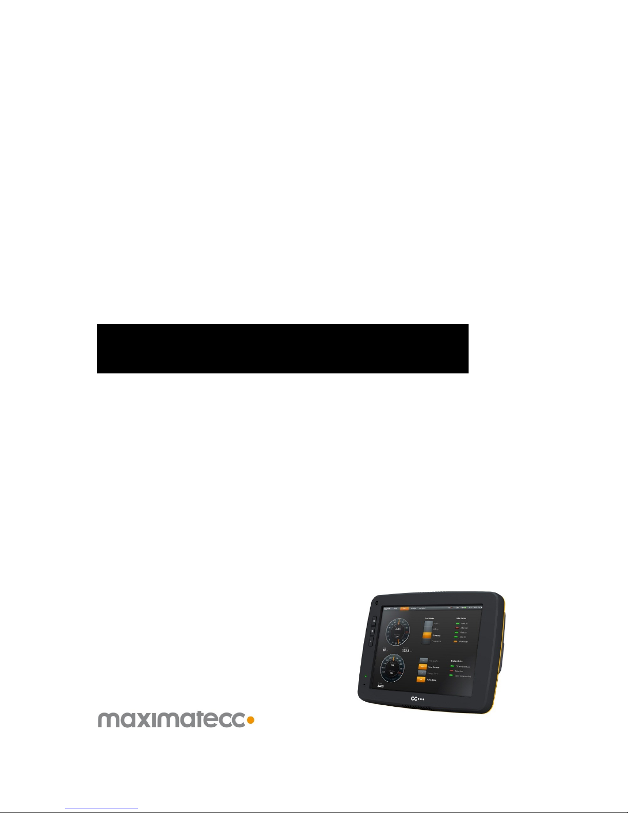
CCpilot XM and CrossCore XM - Software guide
Revision: 1.6
Software Guide
Date: Jun 24, 13
Software guide
www.maximatecc.com
CCpilot XM and CrossCore XM
Page 2

CCpilot XM and CrossCore XM - Software guide
Revision: 1.6
Software Guide
Date: Jun 24, 13
www.maximatecc.com
Contents
Revision history ..................................................................................................................................4
1. Introduction ..................................................................................................................................5
1.1. Conventions and defines ......................................................................................................... 5
1.2. Identification .............................................................................................................................. 5
1.3. References .................................................................................................................................. 6
2. Basic operation ............................................................................................................................7
2.1. Login and passwords ................................................................................................................ 7
2.2. Using the touch screen............................................................................................................. 7
2.3. Keyboard .................................................................................................................................... 7
2.4. Calibrating the touch screen .................................................................................................. 8
2.5. Software deployment ............................................................................................................... 8
3. Device start-up behaviour ..........................................................................................................9
3.1. BIOS .............................................................................................................................................. 9
3.2. Windows system start-up specifics ......................................................................................... 9
3.3. Linux system start-up specifics ................................................................................................. 9
3.4. Status LED indication ............................................................................................................... 10
4. Accessing and using the interfaces of XM device ................................................................11
4.1. CF/HDD ...................................................................................................................................... 11
4.2. CAN ............................................................................................................................................ 11
4.3. Ethernet ..................................................................................................................................... 12
4.4. USB .............................................................................................................................................. 12
4.5. RS232 Serial access ................................................................................................................. 12
4.6. Video in ..................................................................................................................................... 12
4.7. Audio In / Out ........................................................................................................................... 12
4.8. Digital Input............................................................................................................................... 13
4.9. Status LED .................................................................................................................................. 13
4.10. Backlight ............................................................................................................................ 13
4.11. Ambient light sensor ........................................................................................................ 14
4.12. Buzzer ................................................................................................................................. 14
4.13. EEPROM ............................................................................................................................. 14
4.14. Hardware watchdog functionality .............................................................................. 14
4.15. Temperature sensors ....................................................................................................... 14
4.16. GPS ..................................................................................................................................... 14
4.17. GPRS/GSM ........................................................................................................................ 15
4.18. WLAN ................................................................................................................................. 15
4.19. Bluetooth ........................................................................................................................... 15
5. CCsettings ...................................................................................................................................16
5.1. Main menu ................................................................................................................................ 16
5.2. Version ....................................................................................................................................... 16
5.3. Temperature ............................................................................................................................. 16
5.4. Display ....................................................................................................................................... 17
5.5. Power ......................................................................................................................................... 17
5.6. Heater ........................................................................................................................................ 17
Page 3

CCpilot XM and CrossCore XM - Software guide
Revision: 1.6
Software Guide
Date: Jun 24, 13
www.maximatecc.com
5.7. About ......................................................................................................................................... 18
5.8. LED .............................................................................................................................................. 18
5.9. Buzzer ......................................................................................................................................... 18
5.10. CAN .................................................................................................................................... 18
5.11. Digital Input ....................................................................................................................... 19
5.12. Touch screen .................................................................................................................... 19
5.13. Light sensor ....................................................................................................................... 20
5.14. On/Off ................................................................................................................................ 20
5.15. Advanced ......................................................................................................................... 21
5.16. Telematics ......................................................................................................................... 21
6. CCvideo ......................................................................................................................................22
6.1. CCvideo main window .......................................................................................................... 22
6.2. Selection menu ........................................................................................................................ 22
6.3. Input info ................................................................................................................................... 23
6.4. Video cropping ........................................................................................................................ 23
7. Software update and recovery ................................................................................................24
7.1. Restore firmware settings ....................................................................................................... 24
7.2. Updating firmware components .......................................................................................... 24
7.3. Updating system components .............................................................................................. 24
7.4. Reinstalling the operating system......................................................................................... 24
8. Linux specifics ............................................................................................................................26
8.1. Linux system content............................................................................................................... 26
8.2. Updating system software ..................................................................................................... 26
8.3. Installing new drivers, applications and system packages ............................................. 27
8.4. IP address configuration ........................................................................................................ 30
8.5. Changing serial port settings ................................................................................................. 31
8.6. Remote access ........................................................................................................................ 31
8.7. Serial Number Broadcast configuration ............................................................................. 32
8.8. Splash screen image replacement ..................................................................................... 33
8.9. Desktop background image replacement ....................................................................... 33
8.10. USB memory installer ....................................................................................................... 33
9. Windows system specifics .........................................................................................................34
9.1. Windows system content ....................................................................................................... 34
9.2. File system layout ..................................................................................................................... 34
9.3. Installing new drivers, applications and system packages ............................................. 34
9.4. Remote access ........................................................................................................................ 34
9.5. Embedded write filter ............................................................................................................. 35
9.6. File based write filter ............................................................................................................... 35
9.7. Hibernate once resume many.............................................................................................. 36
Operating system licensing ...........................................................................................................37
Technical support ............................................................................................................................38
Trade Mark, etc. ..............................................................................................................................38
Page 4

CCpilot XM and CrossCore XM - Software guide
Revision: 1.6
Software Guide
Date: Jun 24, 13
www.maximatecc.com
Revision history
Rev
Date
Comments
P1.0
2011-07-06
-
P1.1
2012-02-17
xx
P1.2
2012-03-30
Update for new windows and Linux system
images.
Licensing and 3rd party SW annotations added.
P1.3
2012-04-04
Small fixes and layout changes
P1.4
2012-11-27
A-I + CrossCore XM
P1.5
2012-12-03
Update after review
P1.6
2013-06-17
Small clarification for WLAN settings in
networking for Linux.
Company name change.
Page 5

CCpilot XM and CrossCore XM - Software guide
Revision: 1.6
Software Guide
Date: Jun 24, 13
www.maximatecc.com
1. Introduction
This software guide contains information on how to start using the CC Pilot XM and CrossCore XM
products and how to access Service functionality.
XM devices are available with both Windows and Linux operating system. This guide is applicable
for both operating systems. Operating system specific information is pointed out in the text or
addressed in the respective operating system sections. Windows may refer to Windows XP Tablet
PC Edition, Windows Embedded Standard 7 or other versions of Windows. Unless otherwise
stated, the information is applicable to all versions of Windows.
The reader should be familiar with the respective operating system and computer usage to fully
benefit from this material.
1.1. Conventions and defines
CCpilot XM and CrossCore XM are in most cases identical in functionality and usage. The following
definition is used to separate unit specific details. The observe symbol is also used to highlight such
difference.
Defines
Use
CCpilot XM
Information that is specific for CCpilot XM
CrossCore XM
Information that is specific for CrossCore XM
XM device
Information that applies to both CCpilot XM and CrossCore XM
The observe symbol is used to highligt information in this document, such as differences between
product CCpilot and CrossCore product models.
The A symbol is used to highlight information specific for CCpilot XM All-Integrated and CrossCore
XM All-Integrated.
The exclamation symbol is used to highlight important information.
Text formats used in this document.
Format
Use
Italics
Paths, filenames, definitions.
Bold
Command names and important information
1.2. Identification
On the side of the XM device there is a label with version and serial numbers which identify your
unique computer. Take note of them. During service and other contact with the supplier it is
important to be able to provide these numbers.
Page 6

CCpilot XM and CrossCore XM - Software guide
Revision: 1.6
Software Guide
Date: Jun 24, 13
www.maximatecc.com
1.3. References
For further information on the XM device and the available APIs see the following references.
[1] CCpilot XM and CrossCore XM – Programmers Guide
[2] SocketCAN in Linux kernel,
http://lxr.linux.no/linux+v2.6.31.14/Documentation/networking/can.txt
[3] CCAux API documentation (CC AUX x.x.x.x, available in the CC AUX SDK)
[4] CAN Interface Description (available within the Windows SDK)
[5] CCpilot XM and CrossCore XM – Technical Manual
[6] Embedded Write filer documentation (MSDN), http://msdn.microsoft.com/en-
us/library/bb521449%28v=winembedded.51%29.aspx
[7] File based write filter (FBWF) documentation, (MSDN), http://msdn.microsoft.com/en-
us/library/ee832762.aspx
[8] Hibernate once resume many (HORM) documentation (MSDN),
http://msdn.microsoft.com/en-us/library/bb521614%28v=WinEmbedded.51%29.aspx
[9] CCpilot XM and CrossCore XM – Performing Operating System Recovery
[10] CCpilot XM and CrossCore XM – Performing Firmware Updates
Page 7

CCpilot XM and CrossCore XM - Software guide
Revision: 1.6
Software Guide
Date: Jun 24, 13
www.maximatecc.com
2. Basic operation
This section provides an overall description on basic usage of XM device.
2.1. Login and passwords
By default auto login is enabled and no passwords are required to start using XM device.
The root/administrators passwords are as follows
Under Linux there is one user per default. The user is ccs and the password is default.
This user has administrator rights by using the sudo approach.
Under Windows there are two users per default. The Windows default administrator user
Administrator with the password CCpilotXM and the user Operator which does not
have any password. The Operator user has administrator rights and automatic login
enabled by default.
Custom users can be added with the tools from respective operating system.
2.1.1. Serial console login (Linux)
By default, the serial port can be used as a login terminal for headless access to the XM device. This
service can however be disabled, if a peripheral connection on serial port is desired. This is
specifically covered in chapter 8.5 Changing serial port settings.
Login service is using the same credentials as mentioned above for serial port terminal access.
2.2. Using the touch screen
Navigate the desktop or any application using the touch screen with a stylus or finger.
Tap the screen to perform the equality of a mouse click.
Double click is performed similar to using an external pointing device. Tap the screen twice
in the same place.
Tap and hold the on the touch screen to perform the equivalent to a right click.
There are two available USB profiles for the touch screen; mouse profile and touch profile.
The profile can be changed in CCsettings or through the CCAux API.
Besides the touch screen, keyboard and mouse connected via USB can also be used.
Touch screen functionality is only available in CCpilot XM product versions.
2.3. Keyboard
There is a virtual keyboard available to input letters and symbols using the touch screen. The
virtual keyboard can be used either via the mouse or the touch screen.
The icon to enable the virtual keyboard looks like this:
in Windows
in Linux
Page 8

CCpilot XM and CrossCore XM - Software guide
Revision: 1.6
Software Guide
Date: Jun 24, 13
www.maximatecc.com
2.4. Calibrating the touch screen
To calibrate the touch screen, open CCsettings. Select Touch and then Calibrate Now. Then follow
the step by step sequence to calibrate the display.
It is also possible to launch the calibration application explicitly from any custom application by
calling the TouchCalibrator application (naming convention applicable per operating system). This
application also take additional arguments to configure the calibration method, such as number of
calibration points (5, 9 or 13 points) and edge distance settings of the calibration points. The 5
point calibration is the default method. The 13 point calibration can be used if the results of the 5
point calibration are not satisfactory. The available command line options can be seen with the --h
or --help option flags.
Touch screen functionality is only available in CCpilot XM product versions.
2.5. Software deployment
There are several methods to add your own software to the device. The standard methods to
transfer software to XM device are to either copy files using the network connection or to use USB
storage devices. To install the software, follow the instructions for the respective software.
Additionally, software can be deployed with remote access functions, see the operating system
specific parts in this document for more information.
Page 9

CCpilot XM and CrossCore XM - Software guide
Revision: 1.6
Software Guide
Date: Jun 24, 13
www.maximatecc.com
3. Device start-up behaviour
At power on, the XM device has an internal microcontroller that monitors the power supply and
performs start-up configurations and power settings. It then supplies the main computer board
with power; from there the device execution begins, starting with the BIOS.
3.1. BIOS
The BIOS is XM device specific BIOS, which performs the initial setup of the main processor and its
on-board peripherals. Once finished, the operating system execution takes over.
During BIOS operation different startup options can be accessed, the BIOS can for instance be used
to occasionally boot from USB attached storage media by pressing the key F11. If other nonstandard BIOS settings are desired, access the BIOS Settings menu by pressing the DEL key during
BIOS startup. BIOS settings changes should normally not be needed and can be affecting specific
functions within the system, so any changes must be careful considered before applying.
3.2. Windows system start-up specifics
Once the Windows operating system is started, normal operating system steps are performed. The
Windows operating system is fully available as standard, with installed device drivers for all
hardware peripherals available.
3.3. Linux system start-up specifics
The Linux operating system, an Ubuntu LTS derivate, has two start-up modes, the normal mode
and the recovery mode. In the normal mode the root file system is write protected, meaning that
any run time settings normally done by the user are discarded after a power cycle.
To be able to perform system settings, the Linux system must be restarted into recovery mode. This
is done with the shell command:
# s u d o r eb o ot -resc u e . s h
This recovery mode enables the write back mode of the root file system; in this mode a user can
perform settings that are kept permanent and the system works as the standard Ubuntu system.
The device can also be started into the recovery mode directly, if a keyboard is attached. Keep the
<SHIFT> key pressed while booting the device normally, then choose the recovery system from the
menu that appears.
The recovery system may be more error prone to file system corruption, it is recommended to limit
the use of this mode. Be careful and perform controlled shutdown and restart operations while in
recovery mode, as well as making sure the device has a steady supply power.
Page 10

CCpilot XM and CrossCore XM - Software guide
Revision: 1.6
Software Guide
Date: Jun 24, 13
www.maximatecc.com
3.4. Status LED indication
This section describes the basic default status LED behavior. The LED is located in different
locations depending on the device type, see Technical Manual for details. Note that the status LED
behavior can be disabled totally and/or overridden by user software through the CCAux API.
3.4.1. Start-up sequence
During startup, the LED indications are as follows:
1. Flashing YELLOW at 1 Hz. Pre-heating is activated and in effect, start-up is delayed while
the device is heated.
2. Flashing YELLOW at 2 Hz. Device start-up phase begins.
3. Operating system is then started, and specific service software begins to execute.
4. Static GREEN. System is operational.
3.4.2. Shutdown sequence
Once shutdown or reboot is initiated:
1. Static YELLOW. Shutting down, rebooting or entering suspended mode.
2. LED OFF. Device is off
3.4.3. Suspend/resume sequence
Once suspend is initiated:
1. Flashing YELLOW at 0.2 Hz. In suspend mode
2. Flashing YELLOW at 2 Hz. Resuming operation
3. Static GREEN. System is operational.
3.4.4. Error indication
There are two different types of error indications available from the status LED:
Flashing RED – An occasional three RED blinks during startup indicates an internal error
that is recoverable, i.e. the system can continue its execution and normal operation. Error
code can be retrieved trough the CCAux API, since the status LED will follow its normal
status indication scheme.
Flashing BLUE – The device becomes non-operational, and seems to be dead, despite
powered on. A number of BLUE LED blinks should be displayed. Record the number of
blinks, as this can be useful in an eventual support contact.
Reason for BLUE LED blinking could be voltage levels out of range, temperature related problems
or internal hardware errors. First steps should be to let device cool off, and verify it has correct
power supply attached, before starting the device again.
Page 11

CCpilot XM and CrossCore XM - Software guide
Revision: 1.6
Software Guide
Date: Jun 24, 13
www.maximatecc.com
4. Accessing and using the interfaces of XM device
This section covers basic usage and access of the XM device hardware. Most of the hardware is
accessed using the default Windows or Linux interfaces but some XM device specific interfaces,
such as CAN and Digital In, require additional software and/or interfaces to be accessed. See the
CCpilot XM and CrossCore XM – Programmers guide documentation for general information
regarding software development using XM device interfaces.
Depending on product model, all interfaces may not be present on your specific model. There may
also be additional methods to access XM device than the ones described herein, depending on
operating system and additional installed software.
4.1. CF/HDD
XM device uses a compact flash based storage. The storage is identified to the system as an IDEdevice, i.e. a normal hard disk drive.
The Compact Flash module is industrial grade classified and has both static and dynamic wear
levelling to prevent a premature aging and to ensure the longest lifetime, still Compact Flash drives
has a limited number of write cycles. It is recommended that the amounts of writing to storage are
limited within the application. Rather keep information in RAM memory and write larger blocks at
one time instead of frequently writing smaller pieces.
Additional details about CF usage recommendations can be found in CCpilot XM and CrossCore
XM – Programmers guide.
4.1.1. Windows
In the maximatecc Windows images, measures have been taken to reduce the number of write
accesses during normal operation. These measures include disabling of file access timestamps and
disabling of prefetching services. Note that the page file is disabled by default; this is to enhance the
life time of the Compact Flash card and reduce the system reserved storage media space. Further
configuration to reduce flash write cycles can be set up by the customer: See chapter 9 Windows
system specifics, for information about the EWF, FBWF and HORM technologies.
4.1.2. Linux
In Linux, the Compact Flash card is partitioned into one root file system, which is write protected,
and one user file system area, which is write enabled by default. The latter area is the preferred
location for user software installations. See chapter 8.3 Installing new drivers, applications and
system packages.
4.2. CAN
XM device has four CAN interfaces with user configurable baud rate and frame type accessible from
the CCsettings application or from registry and/or standard file system settings.
The CAN interfaces can also be accessed in Windows using the proprietary CAN API, further
described in the CAN Interface Description, or with the Linux operating system standard API
SocketCAN. More information can be found in CCpilot XM and CrossCore XM – Programmers
Guide.
Page 12

CCpilot XM and CrossCore XM - Software guide
Revision: 1.6
Software Guide
Date: Jun 24, 13
www.maximatecc.com
4.3. Ethernet
Two Ethernet ports are available on XM device, thus enabling simultaneously connection with two
physical network infrastructures. XM device is per default set up to use DHCP for IP address
retrieval. The network connection settings can be changed within the operating system settings.
Be aware that connecting XM device to a network environment can impose a security threat if not
taking the required security measures.
4.4. USB
Via the USB port, a multitude of devices can be connected to XM device. For some devices, drivers
compatible with the operating system must be installed in order for the device to function. Follow
the instruction from the device supplier for the respective operating system.
4.5. RS232 Serial access
Select COM1 in Windows to access the serial port of XM device.
In Linux the serial port is accessed from dev/ttyS0 and when communicating with the targets, the
settings for serial port to use are 115200-8-N-1. By default the serial port is set up as a login
console, but this can be disabled to allow connection of peripheral accessories. This is specifically
covered in chapter 8.5 Changing serial port settings.
The Serial port in XM device follows RS232 signalling levels, but with a limited set of signals. For
more information see the Technical manual.
Note that the serial port should not be used by any software when performing upgrades of internal
microcontroller firmware. The internals of the device needs to have undisturbed access to the serial
port during this operation.
4.6. Video in
The video in signals can be viewed by the CCvideo application, further described in chapter 6
CCvideo. The video in signals can also be accessed and controlled using the CCAux API.
4.7. Audio In / Out
Audio in and audio out is controlled using the normal operating system functionality. The audio
device is identified as Cirrus Logic HD Audio. Note that the audio input is muted per default.
4.7.1. Linux audio settings
Audio input and output settings can be found from menu System › Preferences › Sound.
For any changes to be persistent they need to be made while the system is in rescue mode.
4.7.2. Windows audio settings
The sound settings can be managed using normal operating system procedures accessible via the
control panel.
In Windows XP the Cirrus Logic audio driver supports the below listed combinations of
frequency/resolutions for playback and recording. If other settings are used, the audio may be
distorted or not audible.
Page 13

CCpilot XM and CrossCore XM - Software guide
Revision: 1.6
Software Guide
Date: Jun 24, 13
www.maximatecc.com
Frequency
Resolution
8Khz
8bit mono
8bit stereo
16bit stereo
12KHz
8bit mono
8bit stereo
16bit mono
16bit stereo
16KHz
8bit mono
8bit stereo
16bit stereo
32KHz
8bit mono
8bit stereo
16bit stereo
44.1KHz
44.1KHz 8bit mono
44.1KHz 8bit stereo
44.1KHz 16bit stereo
48 KHz
48KHz 8bit mono
48KHz 8bit stereo
48KHz 16bit stereo
4.8. Digital Input
The digital input signals are available for software developers using the CCAux API. The digital
input status can be viewed within CCsettings for test purposes.
4.9. Status LED
The status LED in the XM device is used by the computer itself and by the operating system to
indicate different states or to present warnings, as described in 3.4 Status LED indication. The
status LED can also be controlled by the applications running on XM device using the CCAux API.
The blinking frequency and colour of the LED can be controlled. The latest status LED instruction
is always used. The status LED can also be disabled which means that only hardware error codes
and user application behaviour is enabled. Yellow blinking at start-up and static green in
operational mode are turned off.
4.10. Backlight
The XM device has an adjustable backlight intensity level. In addition to the backlight control
buttons on the CCpilot XM front, the backlight functionality can also be controlled from CCsettings
and via software using the CCAux API. The most recent setting is always used. The backlight
buttons are dedicated for backlight adjustment only.
Together with the ambient light sensor it is possible to make a custom, fully automatic, backlight
control. Such an automatic backlight control function is included in CCpilot XM, but it is not
enabled by default. It can be set up in CCsettings or through the CCAux API.
For CrossCore XM, the backlight and ambient light sensor is not available.
Page 14

CCpilot XM and CrossCore XM - Software guide
Revision: 1.6
Software Guide
Date: Jun 24, 13
www.maximatecc.com
4.11. Ambient light sensor
The ambient light sensor measures light levels in front of CCpilot XM; for example it’s used for
automatic backlight control. The ambient light sensor is accessed through the CCAux API. It can
also be accessed for diagnostic through CCsettings.
4.12. Buzzer
In addition to the audio In/Out signals, CCpilot XM is also equipped with a buzzer that can play
tones in various frequency and intensity levels. The buzzer is accessed through the CCAux API. It
can also be accessed for diagnostic through CCsettings.
For CrossCore XM, the buzzer is not available.
4.13. EEPROM
A user accessible EEPROM is available in the device, if such storage is required. It’s not normally
needed since a device of this type can store persistent settings in ordinary files in the file system
instead. The EEPROM is accessed via the JIDA interface.
4.14. Hardware watchdog functionality
There is a watchdog available making it possible for the hardware to monitor an application so it
does not stall the system. The exact behaviour is up to the application software to handle and
configure. This functionality is available using the JIDA interface.
4.15. Temperature sensors
There are several temperature sensors placed internally in the device. Thus it is possible for an
application to retrieve temperature information from the temperatures sensors through the CCAux
API or the JIDA interface, depending on temperature sensor placement.
4.16. GPS
The internal GPS receiver in XM device All-Integrated follows NMEA-0183 standards. To access
the GPS receiver data, you should open up a serial connection to /dev/ttyUSB1 (Linux) or COM4
(Windows), with 8-N-1-9600 settings. Note that the GPS receiver needs to be power on to be able
to operate. This is done with the CCSettings program or through the CC AUX API.
On Linux, the output of the GPS device can be verified with the following command:
# stty - F / d ev /t ty U SB 1 is pe e d 9 60 0 & & c at </de v / t t y US B 1
For Windows, similar serial terminal programs can be used for verification.
Once initiated with an initial read operation, the GPS receiver will start to output NMEA-0183
formatted messages on the serial connection, containing GPS information. It is possible to add
extra GPS software that can format this data and provide a more user-friendly approach to it. The
functionality of the GPS receiver together with the open-source implementation GPSD has been
verified. For more information, see http://gpsd.berlios.de/
NMEA also allows the GPS device to be configured, for more details; locate Fastrax iSuite™ NMEA
manual. It is also possible to use CCSettings for initial verification of GPS receiver functionality, see
more in section 5.16.
Page 15

CCpilot XM and CrossCore XM - Software guide
Revision: 1.6
Software Guide
Date: Jun 24, 13
www.maximatecc.com
4.17. GPRS/GSM
XM device All-Integrated has a GPRS modem for data connections. To access the GPRS/GSM
modem, you should open up a serial connection to /dev/ttyUSB0 (Linux) or COM3 (Windows),
with 8-N-1-57600 settings. Note that the GPRS/GSM modem needs to be power on to be able to
operate. This is done with the CCSettings program or through the CC AUX API.
The GPRS modem supports the standard set of AT commands, so any software that supports the
standard AT command specification using serial communication can be used. For instance, the
current power status is available via the AT command (on Linux):
# chat T I M E O UT 2 ' ' AT | mi c r o c o m -t 5 0 0 0 /d e v/ t ty US B0
For Windows, similar serial terminal programs can be used for the same type of simple verification.
It is also possible to use CCSettings for initial verification of modem functionality, see more in
section 5.16.
4.18. WLAN
XM device All-Integrated supports WLAN, interoperable with the standard 802.11 b/g networks.
Note that the WLAN module needs to be power on to be able to operate. This is done with the
CCSettings program or through the CC AUX API.
In Linux, the wireless tools that are installed on the device can be used for setting up the actual
network. Such tools include the iwconfig, iwlist, iwspy, iwpriv, wpa_supplicant and
wpa_cli commands. Additionally, the network interfaces file can be used for configuring WLAN
settings.
In Windows, the standard operating system network connections can be used for setting up a
wireless connection using the WLAN module.
4.19. Bluetooth
XM devices with All-Integrated options have HCI Bluetooth support. HCI stands for Host
Controller Interface and provides a uniform interface method for accessing Bluetooth hardware
capabilities. The Bluetooth module complies with the Bluetooth 2.1 standard. Note that the
Bluetooth module needs to be power on to be able to operate. This is done with the CCSettings
program or through the CC AUX API.
In Windows, the Microsoft Bluetooth stack is used for communication with Bluetooth devices. In
Windows 7, Bluetooth device settings have been moved to Devices and Printers from the Control
Panel applet. Please see the Microsoft documentation for specific Bluetooth usage.
In Linux, the official Linux Bluetooth protocol stack Bluez is supported, and can be used for
communication with Bluetooth devices. Please see the Bluez documentation for more specific
Bluetooth usage.
Page 16
CCpilot XM and CrossCore XM - Software guide
Revision: 1.6
Software Guide
Date: Jun 24, 13
www.maximatecc.com
5. CCsettings
CCsettings is used for viewing and adjusting XM device specific features and information. Through
the CCsettings main window, the different settings pages are reached, each containing different
areas of settings and information.
All functionality and settings accessed using CCsettings is also available through the CCAux API to
enable integration of settings and functionality within any additional user application, or from the
command line with the tool ccsettingsconsole. For details about this, please see the API
documentation or ccsettingsconsole --help.
Start CCsettings from its menu item or optional desktop shortcut. In Windows, CCsettings can also
be started from the Control Panel.
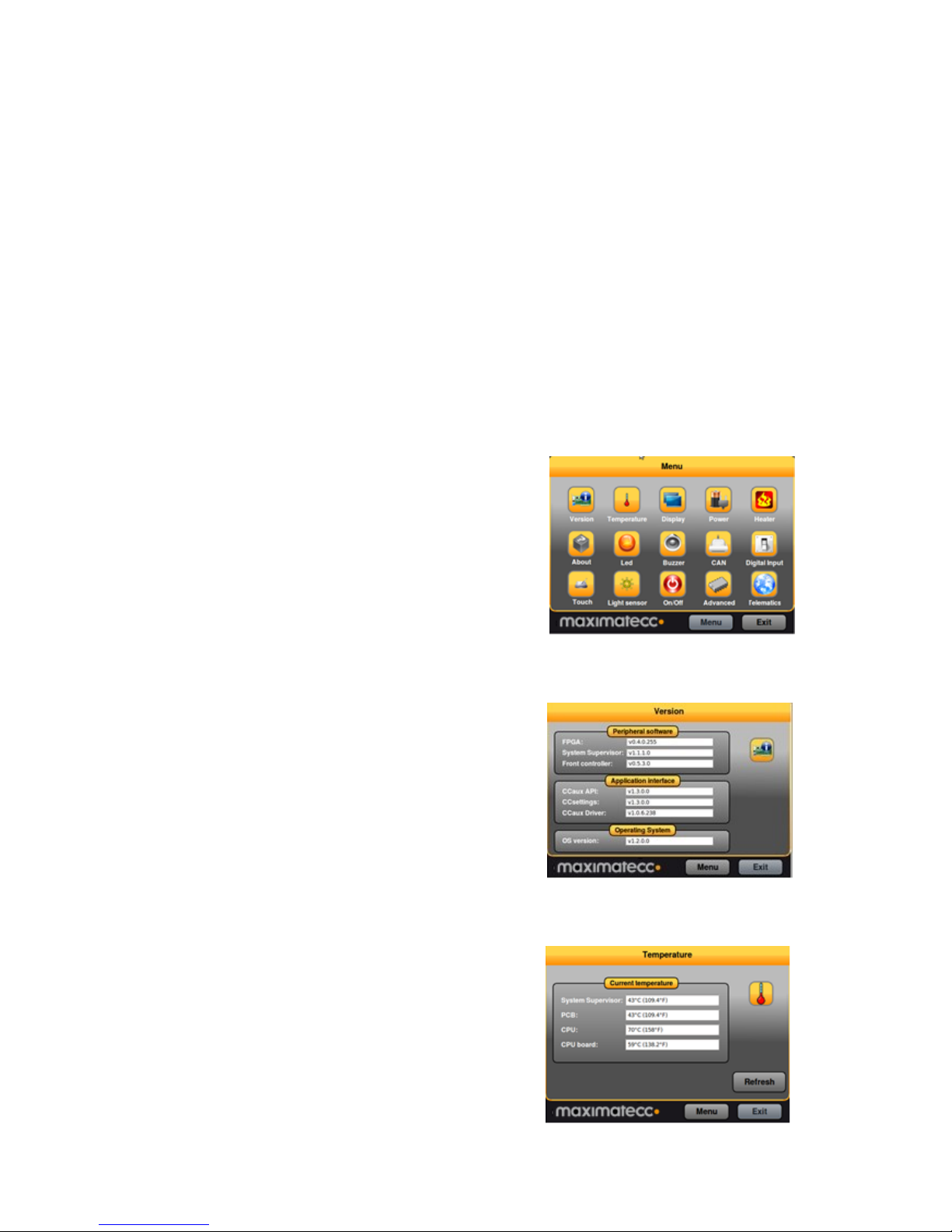
5.1. Main menu
The main screen of CCsettings show the available
settings pages.
Click on the respective icons to enter its settings page.
It is always possible to revert to the main menu by
pressing the Menu button. If a keyboard is in use, the
Escape key can also be used to revert to the main menu.
5.2. Version
The version page displays the XM device internal
software versions, as well as application interface version
and the version of CCsettings itself.
5.3. Temperature
XM device’s internal temperature sensors can be viewed
from the temperature page.
Page 17
CCpilot XM and CrossCore XM - Software guide
Revision: 1.6
Software Guide
Date: Jun 24, 13
www.maximatecc.com
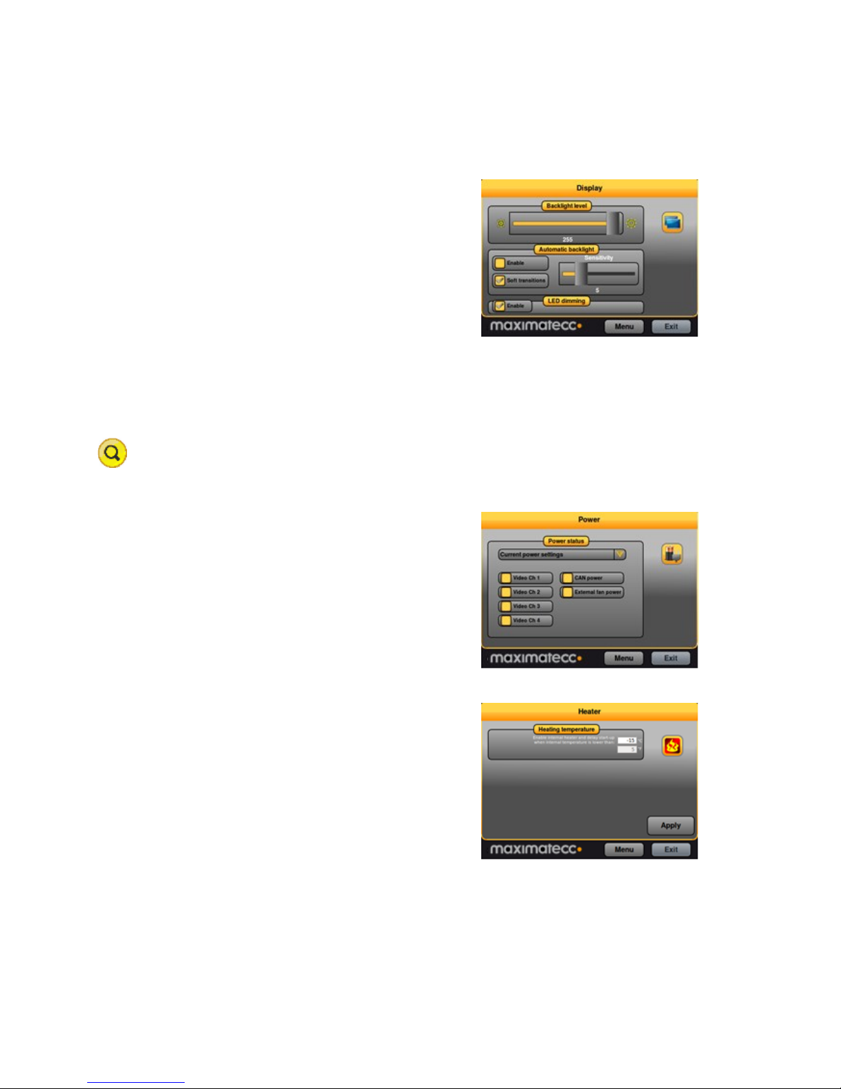
5.4. Display
Use the display page to alter the XM device backlight
functionality.
Adjust the backlight of the display by dragging the
Backlight level slider.
Enable automatic backlight using the Enable checkbox.
The display brightness is then adjusted using CCpilot
XM’s light sensor. Soft transitions enable smoother
adjustment of the backlight.
The Sensitivity slider adjusts the level and phase of
backlight adjustment depending on the surrounding light.
The Status LED can be automatically dimmed according to the backlight setting if LED dimming is
enabled. Note that this may not work if a custom color is used or if a blink sequence is set up by
user applications.
For CrossCore XM, the Display option is not available in CCSettings.
5.5. Power
The power page is used to enable or disable the built in
power controls in XM device.
Enable power by checking the respective check box.
Using the Power status drop down box it is possible to
adjust the current setup or the default setup during
system start-up.
5.6. Heater
The heater page is used to adjust the starting
temperature of the internal heater.
Adjust the temperature and activate the setting by
pressing the Apply button
Page 18
CCpilot XM and CrossCore XM - Software guide
Revision: 1.6
Software Guide
Date: Jun 24, 13
www.maximatecc.com
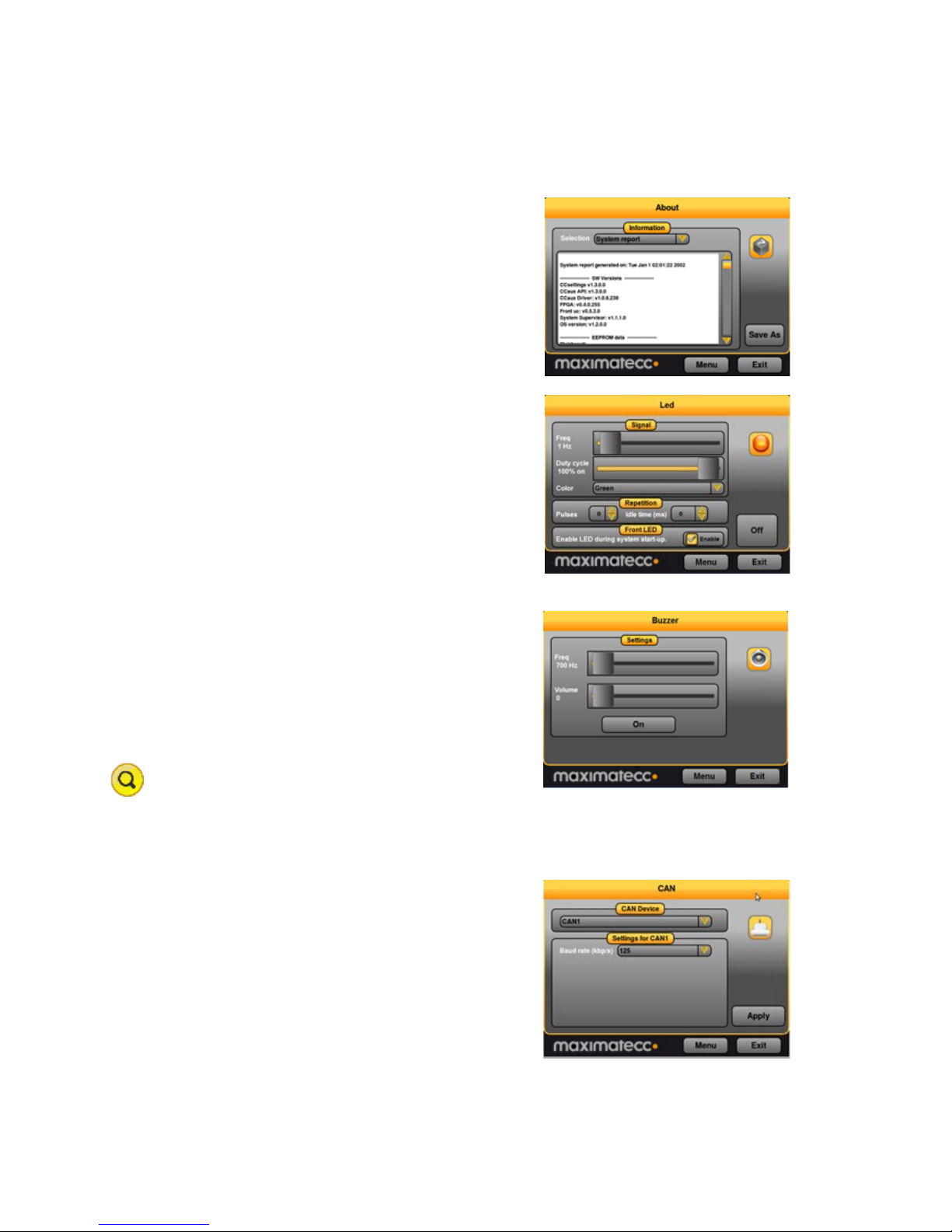
5.7. About
The about page displays device specific information and
status information. Select what type of information to
display using the Selection drop down box.
Select System report drop down to generate a full device
information report, which can be saved to file. This
report can be very useful for service and support
questions.
5.8. LED
The LED page is used to view the possible LED
indication types and to adjust the LED behavior during
startup.
Enable or disable the status LED indication during
startup of XM device using the Enable checkbox.
5.9. Buzzer
The Buzzer page is used to analyze the possible audio
output from the Buzzer.
Adjust the frequency and volume of the built in buzzer
using the sliders.
Test the buzzer sound by pressing the On button. Press
it again to turn off the buzzer.
For CrossCore XM, the Buzzer is not available in
CCSettings.
5.10. CAN
CAN is normally used and configured directly from the
controlling software. But from CCsettings it is possible
to adjust the default Baud rate and CAN Frame type.
The Device drop down box is used to select the CAN
device to adjust.
Page 19
CCpilot XM and CrossCore XM - Software guide
Revision: 1.6
Software Guide
Date: Jun 24, 13
www.maximatecc.com
5.11. Digital Input
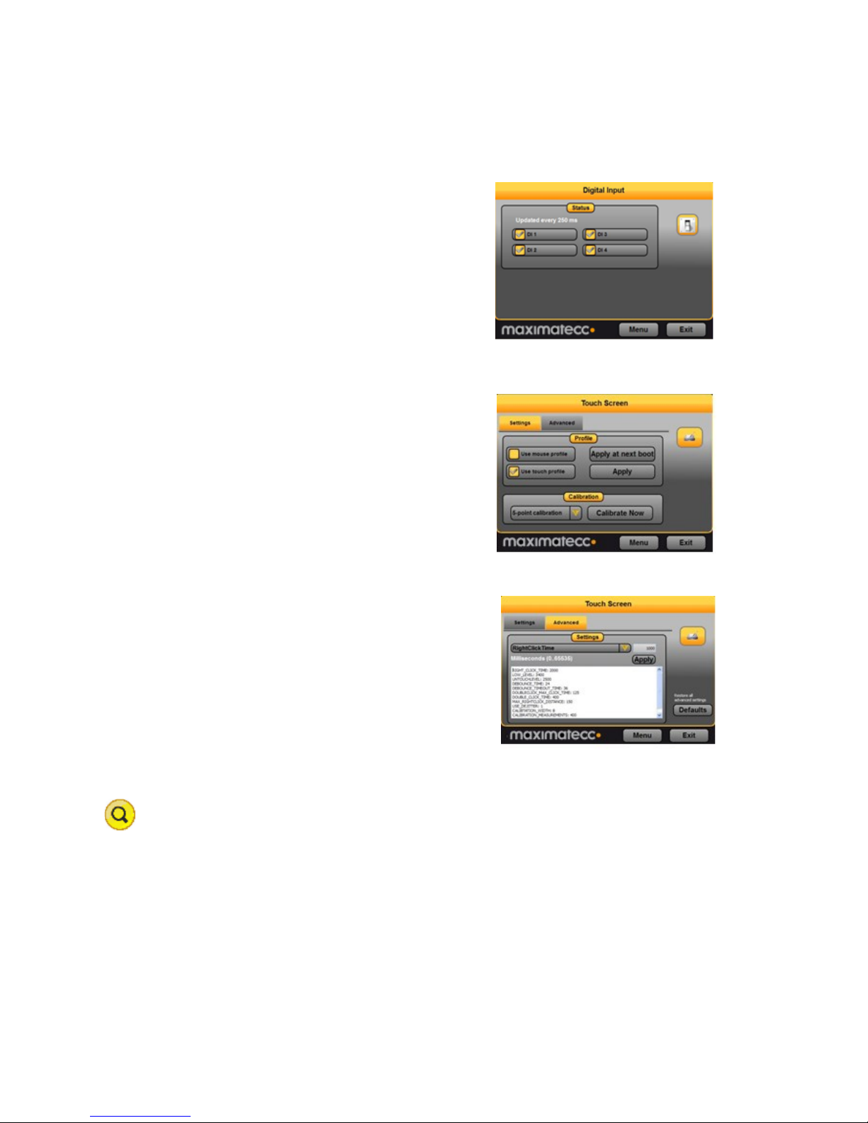
The digital input page displays the status of the digital
input ports on XM device.
5.12. Touch screen
The touch screen page is used to select whether the
touch display shall be identified to the operating system
as a touch screen or as a mouse.
Select Use touch profile to identify the touch screen as a
touch screen, this is the default and preferred setting.
Select Use mouse profile to identify the touch screen as a
mouse, this setting is required for Windows XP-based
installations without the tablet PC component.
If the touch screen if the pointing precision seems low it
is possible to make a calibration. Start the calibration
sequence by selecting Calibrate Now and follow the step
by step sequence. Different calibration methods can be
chosen to perform more precise calibration.
In the Advanced tab, additional touch and calibration
settings can be made. For instance, by entering a time at
Right click time and pressing Apply it is possible to
adjust the time needed until pressing on the touch screen
will result in a right click action. See the CCAux API
documentation for further information on the advanced
settings.
For CrossCore XM, the Touch Screen option is not available in CCSettings.
Page 20
CCpilot XM and CrossCore XM - Software guide
Revision: 1.6
Software Guide
Date: Jun 24, 13
www.maximatecc.com
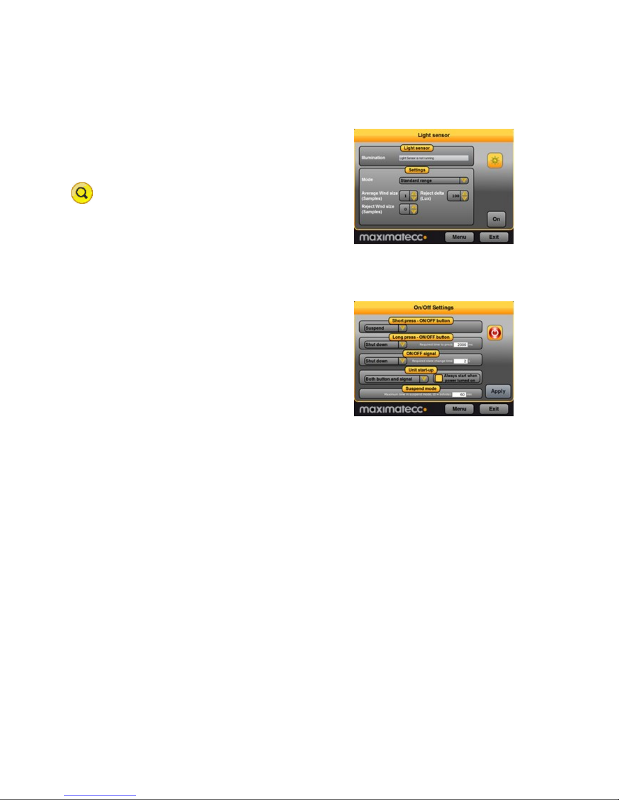
5.13. Light sensor
The light sensor page is used for Light sensor evaluation.
This access is for evaluation, no settings are stored when
leaving the light sensor page.
For CrossCore XM, the Light Sensor option is not
available in CCSettings.
5.14. On/Off
The On/Off page is used to adjust the startup and shut
down settings of XM device.
Any altered setting must be activated using the Apply
button.
Short press - ON/OFF button - adjust the unit behavior
when making a quick press and release of the on/off
button.
Long press - ON/OFF button - adjust the unit behavior
when pressing and holding the On/Off button.
ON/OFF signal - adjust the behavior of the On/off signal through the power connector. The time
settings adjust how long the signal must stay low before XM device reacts to the signal.
Unit start-up makes it possible to select if the unit shall respond to start-up from both the on/off
button and/or the on/off signal in the power connector, or if it shall be configured to start up
directly when supply voltage is applied.
Suspend mode is used for activating automatic transition from suspend mode to shut down of the
computer. The time defines the amount of minutes XM device shall remain in suspend mode before
shutting down. Setting the time value to 0 disables the shut-down feature; XM device will stay in
suspended mode indefinitely, until started or until power is removed.
Page 21
CCpilot XM and CrossCore XM - Software guide
Revision: 1.6
Software Guide
Date: Jun 24, 13
www.maximatecc.com
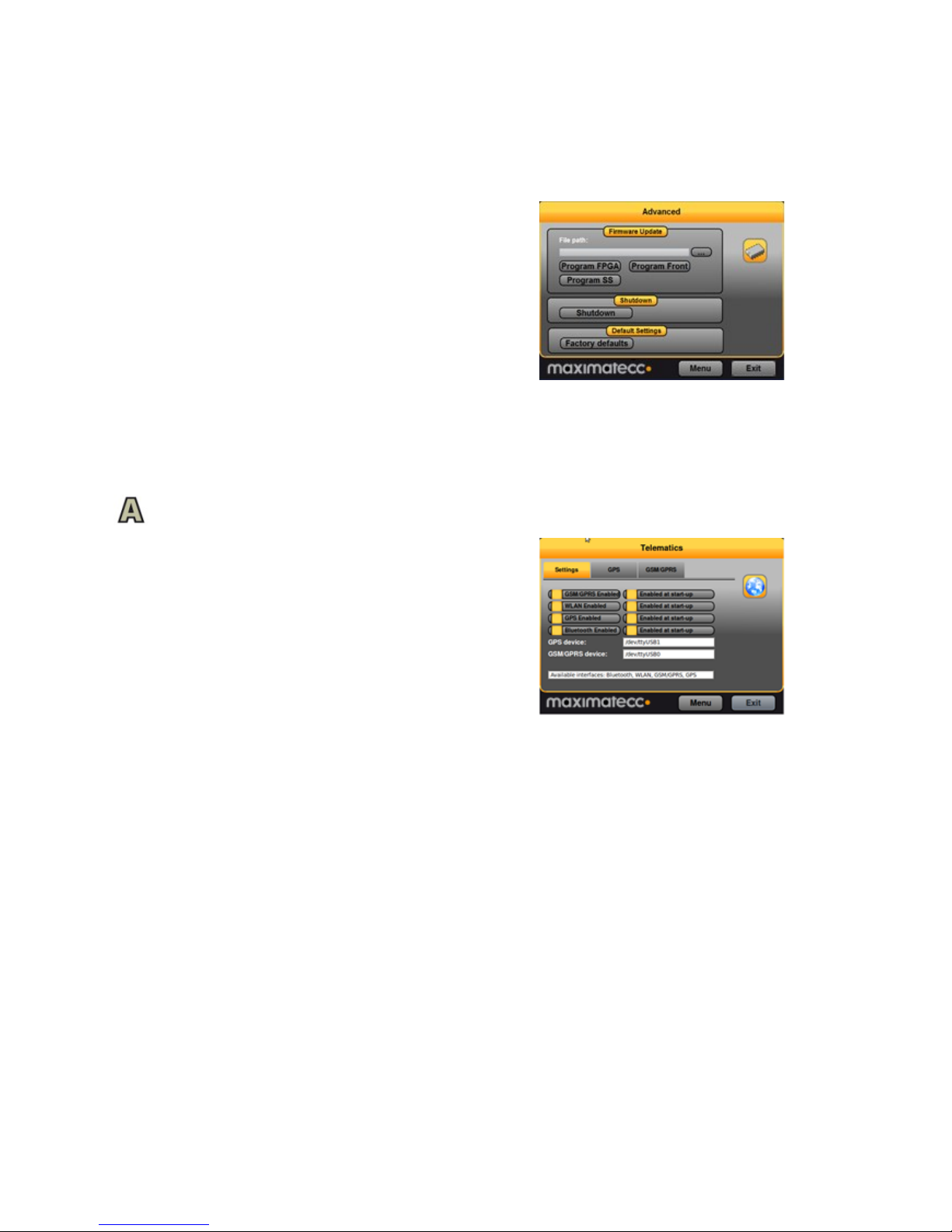
5.15. Advanced
The Advanced page is used for loading new firmware
into XM device and to restore settings to factory
defaults.
To update the respective firmware, make sure the
firmware file is located on the device. Browse for the
appropriate file, then press the corresponding upgrade
button and wait for the firmware update to complete.
Note that no other software can use the serial port of
the device while upgrading the SS or Front controller.
This includes the serial console usage under Linux, and thus an upgrade must disable this prior to
starting the upgrade.
For detailed information about how to upgrade the firmware, please see [10] CCpilot XM and
CrossCore XM – Performing Firmware Updates.
5.16. Telematics
The Telematics page is used for control of All Integrated
functionality such as the GPRS modem, the GPS
received, the Bluetooth module and the WLAN chip.
You can control when to apply power to the specific
peripheral and thus enabling the specific functionality,
either as one time power on or off operation, or as
permanent startup setting.
Additionally, the GPS receiver and the GSM/GPRS
modem have additional status information and
command possibilities in their specific tabs.
Page 22
CCpilot XM and CrossCore XM - Software guide
Revision: 1.6
Software Guide
Date: Jun 24, 13
www.maximatecc.com
6. CCvideo
CCvideo is a pre-loaded application for viewing the CCpilot XM video in signals. Two video signals
can be simultaneously displayed, using any of the four input channels.
All functionality and settings accessed using CCvideo is also available through the CCAux API to
enable integration of settings and functionality within any additional user application.
Video functionality viewing is not applicable for the CrossCore XM.
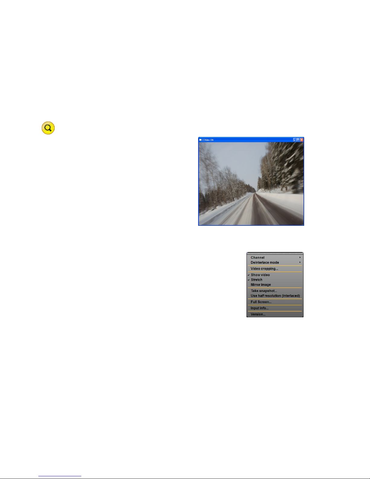
6.1. CCvideo main window
When starting CCvideo the main window will be
shown. This window displays the currently selected
video signal.
6.2. Selection menu
The selection menu is activated by right clicking within the CCvideo window.
---- - Lock the menu visible.
Channel - Select the video in signal to display.
Deinterlace mode - Select deinterlace mode for video
generation.
Video cropping - Opens the Video cropping dialog.
Show video - Enables/disables the video in feed to be
displayed.
Stretch - Enables/disables stretching of the video image to fit the size of the CCvideo
application window.
Mirror image - Enables/disables video image mirroring.
Take snapshot – Take a snapshot of the video image. The image will be saved to disk and
the user will be asked if he wants to view the image in the OS default image viewer.
Use half resolution (interlaced) – Setting for the snapshot function. If enabled, the
snapshot image will only use half of the original video resolution. This function is intended
to be used by custom applications if disk/memory usage and performance of capturing
images are critical.
Full Screen – View video in full screen mode.
Input info - Displays input information for the currently viewed video in feed.
Version – Display the software version of CCvideo.
Page 23
CCpilot XM and CrossCore XM - Software guide
Revision: 1.6
Software Guide
Date: Jun 24, 13
www.maximatecc.com
6.3. Input info
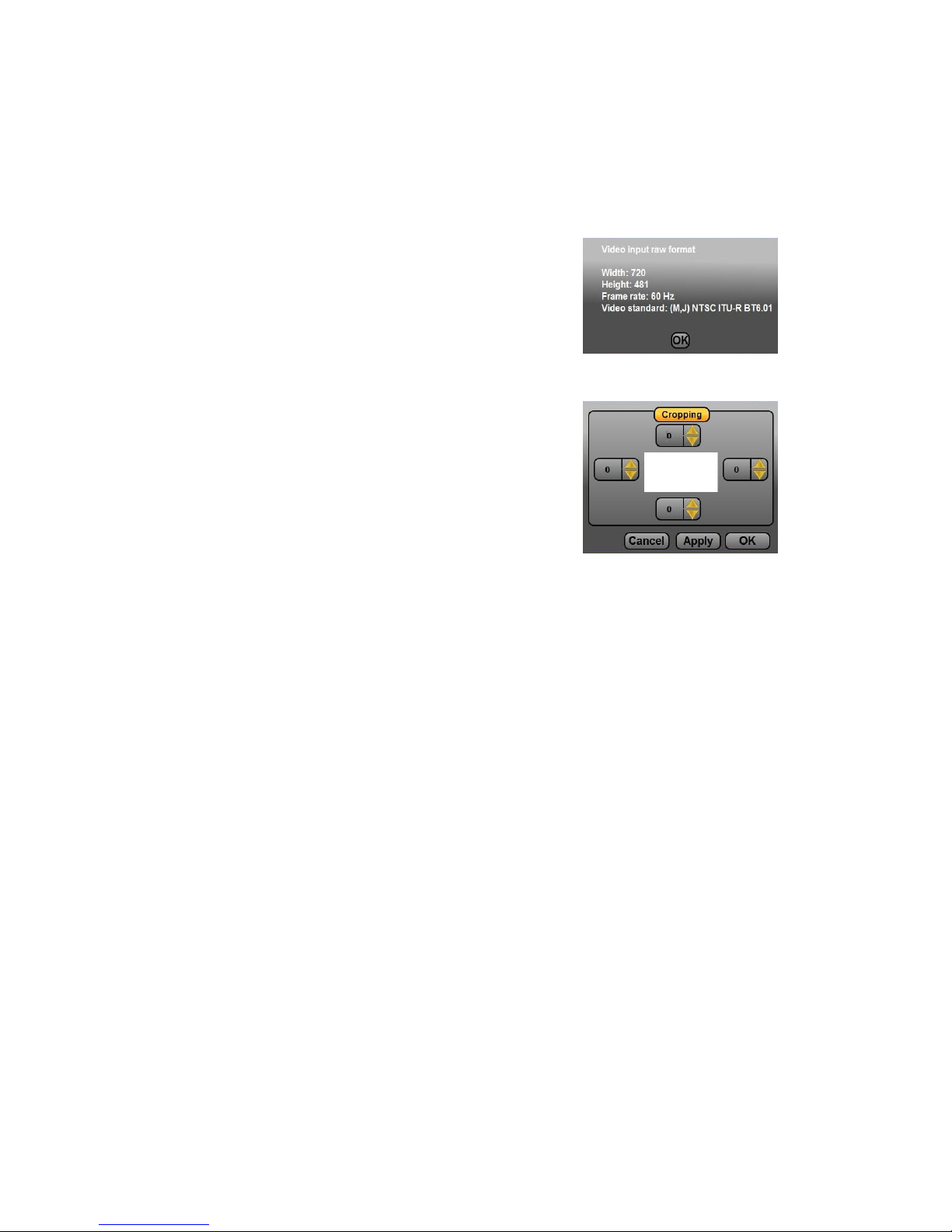
The input info dialog displays information for the currently used video in feed.
With - Native with of the signal in pixels.
Height - Native height of the signal in pixels.
Frame rate - Current frame rate of the video signal.
Video standard – The detected video standard of the
video signal.
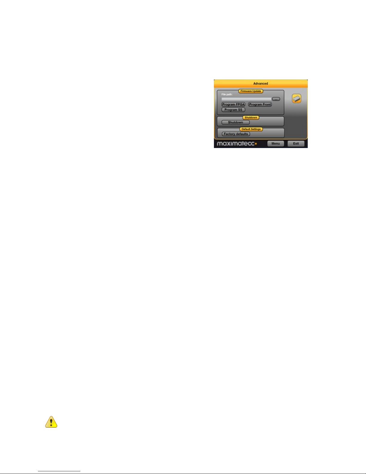
6.4. Video cropping
Use the video format settings to adjust the video being shown.
Cropping - Removes black or unwanted parts of the
video signal. The video feed is cropped by the number
of lines set for each part of the picture.
Page 24
CCpilot XM and CrossCore XM - Software guide
Revision: 1.6
Software Guide
Date: Jun 24, 13
www.maximatecc.com
7.
Software update and recovery
7.1. Restore firmware settings
CCsettings can be used to reset the firmware settings to
the factory default settings, if needed. Start CCsettings
and press the Factory defaults button from the Advanced
page.
7.2. Updating firmware components
The XM device has three different firmware components; The System Supervisor is a
microcontroller that controls the power configuration within the device. The Front microcontroller
controls the functionality available in the front, including LED, Buzzer and touch screen handling.
The FPGA implements different communication controller interfaces internally in the device.
Each of these firmware components can be updated, either individually or batched. The preferred
method to perform the update is by using the CCSettings program, as briefly mention in section
5.15. It is also possible to use the command line based application ccsettingsconsole, or from your
own program using the CC AUX API functions.
For specific details on how to perform firmware component updates, please see [10] CCpilot XM
and CrossCore XM – Performing Firmware Updates.
7.3. Updating system components
Updated system components can be installed in XM device to enable new features or provide
enhancement on existing functionalities.
XM device specific drivers, interfaces and applications are updated using updated software
packages available from maximatecc or your sales contact. These packages contain
installation instructions or such instructions are available separately.
Firmware for XM device internal functionality is mainly updated through CCsettings.
General operating system updates are added using the operating system update methods,
such as installers and software packages
7.4. Reinstalling the operating system
If the operating system needs to be reinstalled it is advised to use the custom XM device operating
system images, available through maximatecc’s on-line support pages or your support contact.
These operating system images have the same content as the pre-installed operating system. There
is a separate operating system recovery manual that can be followed, see [9] CCpilot XM and
CrossCore XM – Performing Operating System Recovery for a more thorough description.
When re-installing XM device, all stored material such as user saved data and computer
configuration will be lost. Backup all necessary information before re-installing the operating
system.
Page 25

CCpilot XM and CrossCore XM - Software guide
Revision: 1.6
Software Guide
Date: Jun 24, 13
www.maximatecc.com
Page 26

CCpilot XM and CrossCore XM - Software guide
Revision: 1.6
Software Guide
Date: Jun 24, 13
www.maximatecc.com
8. Linux specifics
This section describes specific details for systems running Linux.
8.1. Linux system content
The Linux operating system is an Ubuntu LTS (lucid) derivate, using customized desktop and
slimmed contents with limitations in package management, together with a real-time kernel and
interfaces to access the XM device specific hardware and functionality.
Additionally, the file system is changed to a union file system, making the real root file system write
protected where all system changes are normally only valid for one session.
To see which software packages are installed in the XM device Linux system, list them with the
following command:
# d p k g - l
For general Ubuntu setup and system configuration, please see the Ubuntu documentation.
8.1.1. Linux drivers
Dated 2012-03-01, the Linux driver content is as follows, i.e. this specifies the 3rd party software
that is used in XM device:
Usage
Provider
Driver
Graphics
Intel
EMGD v 1.5.1742
8.2. Updating system software
System software can be updated either writing complete new disk image or install updated
packages. The preferred method is to use package based updates.
8.2.1. Image based update
With this method all the user modifications to the system will be erased. Device will be set to same
state as it would be when left from factory. This method can be used to recover devices that for
some reason have corrupted system software. This is also simplified with the tools mentioned in
[9].
Boot the device from Linux LiveCD – image, for example Ubuntu LiveCD. If an update LiveCD –
image, containing update system image, is provided, use it instead. USB – boot device is needed to
be selected during boot up at BIOS screen by pressing F11 key.
After device has done booting the Live Linux system, start terminal from menu Applications ›
Accessories › Terminal. Use the following command in terminal to write image from network. In
this example version 1.2.0.0 is used, but it should be replaced to match current version, as well as
replacing the correct path to the actual image file.
# ssh u s e r @ c om pu t e r ‘cat pa t h / t o /i m ag e/ cc p -xm- l i n u x -
v1 . 2 . 0 . 0 .g z ’ | g zi p –d | s u d o d d o f= / de v/sda b s = 1 0 0 M
After that command, the system will ask for a password and then start writing the image. Image
writing takes a few minutes in which time nothing will be printed on screen. After image writing is
complete, the unit should be shutdown. Take out the USB-memory stick and start the device.
Page 27

CCpilot XM and CrossCore XM - Software guide
Revision: 1.6
Software Guide
Date: Jun 24, 13
www.maximatecc.com
For a LiveCD with update image, use following command. Also here the v1.2.0.0 is used as an
example only.
# c a t c c p- xm-linu x - v 1 .2 . 0. 0 .g z | g z ip –d | s u d o d d o f= /d ev / sd a
bs = 1 0 0 M
8.2.2. Package based update
With this method user modifications won’t be erased. Updates should be done one step a time and
no version should be skipped. Only single version step update is supported, and OS version must be
1.1.0.0 or higher to support the package based update process.
To update device with this method first it needs to be booted to rescue-mode. That can be done
either pressing shift-key during boot to get grub-menu and select Recovery-kernel. Another way is
to open a terminal and execute the following command.
# s u d o r eb o ot -resc u e . s h
Once the device is in recovery-mode, transfer the update-package to the device. Open a terminal
and execute the following commands. Version 1.2.0.0 is used as an example only.
# t a r x f < p ac k ag e-nam e >
# cd c c p - xm- u p da te -v 1 .2 .0 .0
# s u d o i ns ta l l -ccp - xm- u p g r a de .s h
After the installation has finished, the update-package and ccp-xm-update-v1.2.0.0 – directory can
be removed. Reboot the device.
8.3. Installing new drivers, applications and system packages
All additional software or user files should normally be installed and stored under the user
partition /opt/, which is mounted read-write. Under /opt, a limited set of standard directories are
found which are always writable, those directories are /opt/etc, /opt/bin, /opt/lib, and /opt/sbin.
Package manager can be used for adding, removing and updating applications. This requires the
recovery system to be running, if the package manager needs to track the added packages after a
reboot. It is still recommended to install extra software to the user partition.
To perform updates to the system, reboot the system into recovery mode using the command
below. Normal software installations to /opt parts does not require usage of the recovery system.
# sudo r e b o o t-resc u e . s h
8.3.1. Remounting file system in read-write mode
It is possible to temporarily mount the file system writeable, to allow edit of protected files, using
the following commands.
# s u d o m ou n t –o re m o u n t ,r w /r o
Important, remember to use the following command to remount the file system as write protected
again, before shutting down or restarting the device.
# s u d o m ou n t –o re m o u n t ,r o /r o
Page 28

CCpilot XM and CrossCore XM - Software guide
Revision: 1.6
Software Guide
Date: Jun 24, 13
www.maximatecc.com
8.3.2. Text editor
The text editor gedit is available per default for text editing. The console text editors vi and nano
are also available.
8.3.3. User libraries
To install additional shared libraries, install the library files into /opt/lib/. Then, update the used
library cache file by executing the following command:
~# sudo l d c o n f ig -C / o p t / et c / ld .s o. c ac h e
If additional library file locations are needed, the paths of these can be added to above command as
parameters. The environment variable $LD_LIBRARY_PATH can also be used for finding library
files not in the cache.
Library cache file is never automatically updated. But if the file does not exist at system start-up, it
is re-created with default version containing information only about the standard libraries.
8.3.4. User binaries
Additional binaries such as customer application software or additional open-source solutions are
preferably installed to /opt/bin/ or /opt/sbin/. These directories are available in the standard path,
adding binaries to these locations does not require an update to the $PATH environment variable.
If additional levels of binaries are required, the $PATH environment variable must be updated
through a start-up script.
8.3.5. Start-up scripts
The user has the possibility to start applications and scripts by modifying or adding start-up scripts.
When the kernel is started, the start-up script rc located in /etc/init.d/ is executed. Normally, this
script reads start-up scripts under /etc/rcX.d/, depending on the actual run level X.
The default run level is 2, so applications should at least have startup scripts for this run level. The
rc script has been modified to parse additionally start-up scripts found in /opt/etc/rcX.d/ as well
as standard system scripts. The parsing is done in a temporary directory, so scripts from each
source location are interleaved depending on their respective names as described below.
To start applications in run level 2, create a script located in /opt/etc/rc2.d/ that starts the desired
applications. This is the default run level. Each script must be named SXXname, where XX is two
digits and corresponds to the order of the script execution. Also note that these scripts are usually
sourced, so no exit should be performed within these scripts.
The scripts should follow the correct format for the start-stop daemon to work correctly. For more
information on how the scripts should be created, see the Ubuntu standard documentation.
Run level 6 is dedicated for shutdown. When device is shutting down the scripts from /etc/rc6.d/
and /opt/etc/rc6.d/ are executed to perform last clean-up actions. Required naming and execution
order rules comply with start-up level 2, but kill scripts are normally named KXXname instead.
Note that for graphical applications to be started using start-up scripts, some actions such as
waiting for the graphics system startup must be considered in these scripts. A good example is to
wait for gnome-sessions and use $DISPLAY=:0.0 environment variable in the scripts.
Page 29
CCpilot XM and CrossCore XM - Software guide
Revision: 1.6
Software Guide
Date: Jun 24, 13
www.maximatecc.com
8.3.6. Gnome auto-start
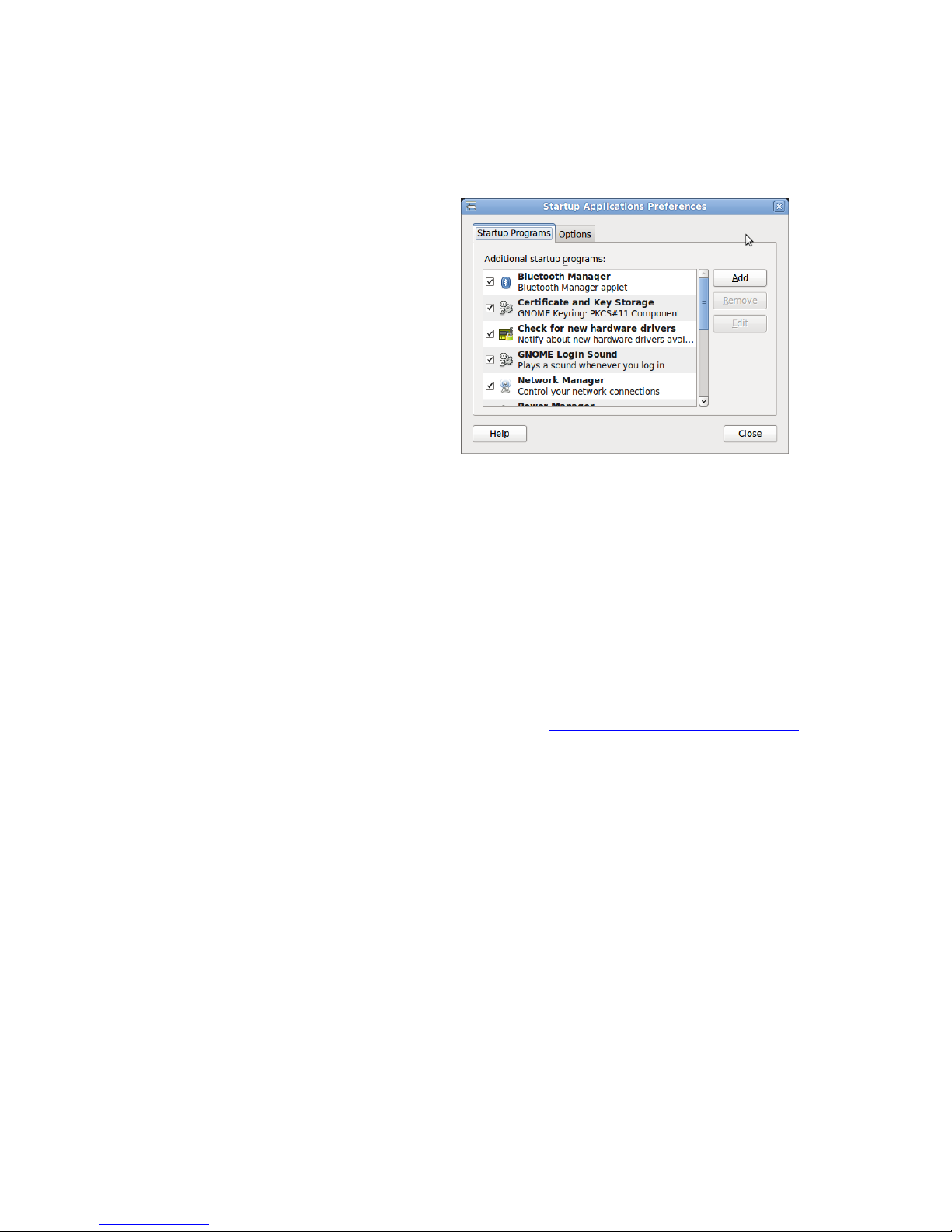
Specific gnome-autostart configuration can
be also used for automatic application
startup.
Note that this method does not provide the
correct application signaling that could be
required when a device is powered off. For
that reason, if any application data needs to
be saved, application started with this
method needs to handle a SIGKILL signal
within a very short time frame.
The gnome-autostart congiguration is
accessed through the menu: System >
Preferences > Startup Applications. Add
your application using the dialog Add button.
8.3.7. Upstart jobs
Upstart is an event-based replacement for the /sbin/init daemon which handles starting of tasks
and services during boot, stopping them during shutdown and supervising them while the system is
running.
The XM device Linux system also uses upstart to be able to schedule applications starting correctly.
It is a stable way of adding automatically started applications, which is an improvement compared
to the standard start up scripts. The drawback is that you are required to perform your additions in
the recovery mode, but the benefit is the stability for applications receiving proper startup and
shutdown signals from the operating system framework.
Detailed instructions on how to use upstart can be found at http://upstart.ubuntu.com/cookbook/.
Page 30
CCpilot XM and CrossCore XM - Software guide
Revision: 1.6
Software Guide
Date: Jun 24, 13
www.maximatecc.com
8.4. IP address configuration
There are several ways of setting the IP address of a
device. The default method is DHCP, but a static IP
address can also be used. This can be done either or
through the network interfaces configuration file.
8.4.1. GUI method for IP address
configuration
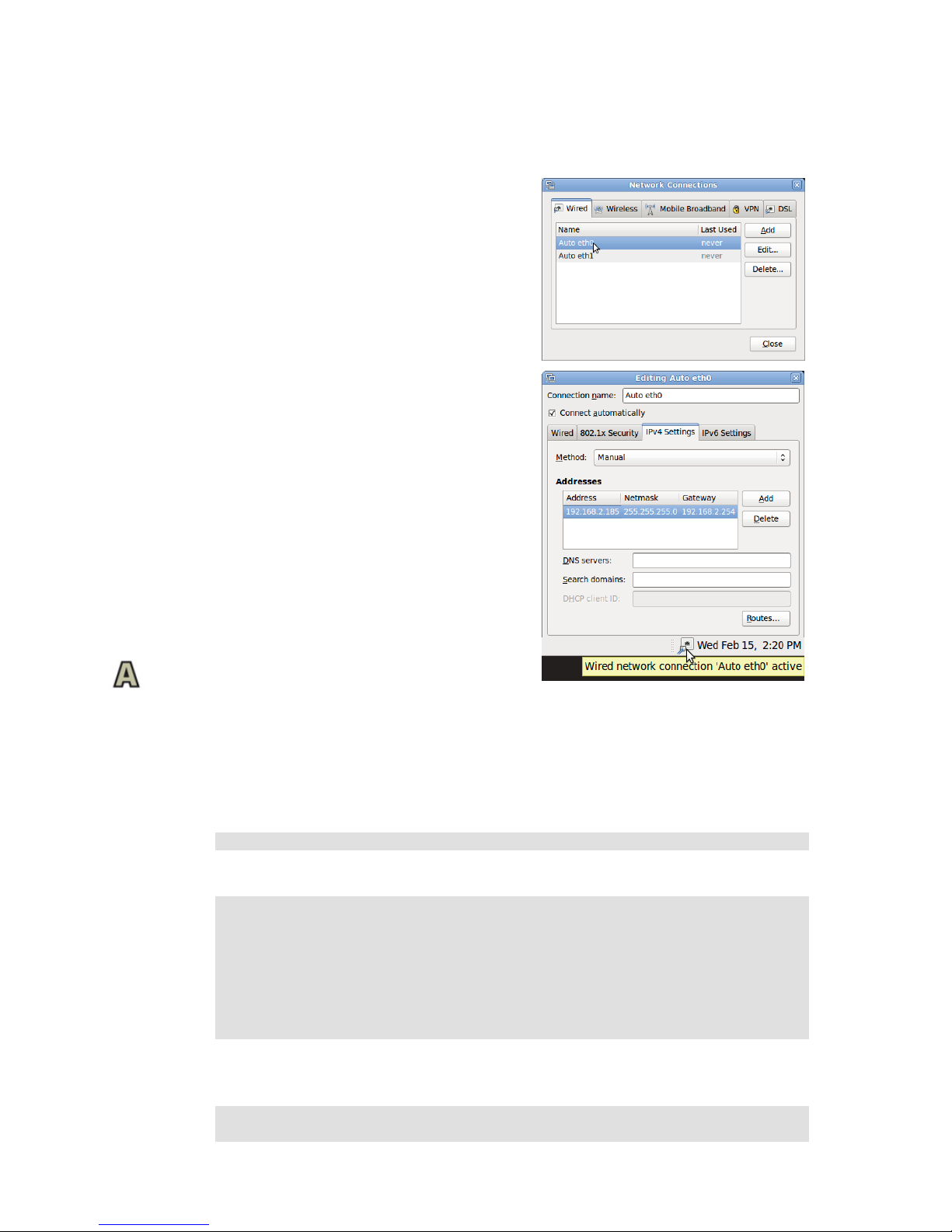
Open the network connection settings using:
System -> Preferences -> Network Connections ->
Wired (or other)
Once there, open the corresponding port with the Edit
command and perform the settings. See screenshot for a
sample configuration.
Once the Apply button is pressed the dialogs can be
closed and the IP address should be set up. The network
interfaces might require a reset for the changes to effect,
either restart the device or press the top menu
networking icon to toggle a network interfaces reset.
The network manager should also be used when
configuring the WLAN connection details, but the
interface name will be different then.
8.4.2. File method for IP address configuration
The network interfaces file is located in writable storage, but the edit process has been made
transparent to that fact. This method requires knowledge about the interfaces file format, but a
sample is given below.
# sudo g e d i t / et c/ n e twork / i n t e r fa c es
Sample of interfaces file setting same static address as the graphical method above.
au t o l o
if a c e l o i n et lo op ba c k
au t o e t h 0
if a c e e t h0 in e t st at i c
ad d r e s s 19 2 .1 6 8. 2. 18 5
ne t m a s k 25 5 .255. 2 5 5 . 0
ga t e w a y 19 2 .1 6 8. 2. 25 4
Once the file has been edited, it is recommended to either reboot the device, or to bring the network
interfaces down and up again, for the IP address configuration to take effect.
# s u d o i fc o nf i g et h0 do wn
# s u d o i fc o nf i g eth0 u p
Page 31

CCpilot XM and CrossCore XM - Software guide
Revision: 1.6
Software Guide
Date: Jun 24, 13
www.maximatecc.com
8.5. Changing serial port settings
By default the serial port is set up as a console, but this can be disabled to allow connection of
peripheral accessories, or to allow firmware components upgrade. The serial port is accessed from
dev/ttyS0 and when used as a serial console, the settings for serial port are 115200-8-N-1.
To disable the serial console do the following:
# sudo d i s a b le -s er ia l-cons o l e . s h
Use the following command to enable it again
# sudo e n a b l e-seri a l - co n s ol e. sh
When the serial port is not used as a serial console, i.e. disabled, the settings can be changed to fit
your connection requirements with standard serial port operations.
8.6. Remote access
The methods described in this chapter require an IP address being assigned to the XM device.
8.6.1. SSH
To connect to the XM device, issue the following command (and give password when asked):
# s s h c c s@ X. X. X . X
To connect to a host from the XM device, issue the following command:
~# s s h U se r na m e@ X. X. X .X
Above X.X.X.X is known as an SSH server IP address, with username Username. A password might
be necessary.
8.6.2. SCP
To copy a file to target use the following command (and give password when asked):
# s c p F i le 1 ccs@ X . X . X .X :/ op t/ Fi l e
To copy a file from target use the following command (and give password when asked):
# s c p c c s@ X. X. X . X: /opt/ F i l e F il e
To copy a file from a host while on a XM device to a host, use the following command:
~# s c p F il e U s er na me @ X. X. X. X :F i le
To copy a file from the XM device to a host, use the following command:
~# s c p U se r na m e@ X. X. X .X :F ile F i l e
Above X.X.X.X is known as an SSH server IP address, username Username. A password might be
necessary.
8.6.3. Password-free login for SSH and SCP
Even though the ccs user has password, SSH-connections can be configured to connect without
password, using identity files. This method is mainly useful for remotely executed scripts or alike.
Page 32

CCpilot XM and CrossCore XM - Software guide
Revision: 1.6
Software Guide
Date: Jun 24, 13
www.maximatecc.com
On connecting host (not the target XM device), execute the command below and enter an empty
passphrase when prompted.
~$ s s h - k ey ge n -t r s a -f x m 1 _ r s a
Copy (or append) the created xm1_rsa.pub file into target XM device as a
/etc/ssh/authorized_keys -file. Note, this method needs to be done in recovery mode.
Move the xm1_rsa file to a usable location (e.g. ~/.ssh/ )
Either configure the id-file into use in ssh_config or assign it when executing ssh or scp.
~$ s s h - i ~/ .s s h /x m1 _r s a cc s@ xm -linux
8.6.4. Remote command execution
After password-free login is enabled, any commands can be started remotely without login.
~$ s s h c cs @ xm -linu x " l s - al / o p t/"
If starting services or background tasks, append "&" to command between quotes.
8.6.5. VNC
The XM device Linux version also has a VNC server enabled, so that the GUI desktop can be
accessed remotely, for instance when using CrossCore XM headless devices.
To access the device via VNC, you will need to use a VCN viewer application and enter the IP
address of the XM device, along with the password when prompted for.
8.7. Serial Number Broadcast configuration
The XM device Linux version can identify itself over the IP network by sending out its serial
number as a broadcast IP packet. The Serial Number Broadcast (SNB) service is started by default
at device boot-up and will broadcast a specific identification message to the local network every
fifth second. The message send frequency can be modified and the service can be completely
disabled using the configuration file /opt/etc/ccsnb.conf. This file does not exist by default. Default
values are used if any value is unset or the file does not exist.
# S e r i a l N u mb e r Br oa d ca st – c o n f i g u ra ti on .
# L i n e s be g in n in g with ‘ # ’ a r e co mm e n ts . U n n e c e ss ar y opti o n s
ca n b e o mi t te d .
# M e s s a g e s en d i nt er v al i n s ec o nd s
IN T E R V A L =1 0
# S e r v i c e d is a bl e sw i tc h (D I SA B LE |O FF | 0 )
#A C T I V E = DI S AB L E
# A d v a n c ed fe a tu re s o nl y. U s e w it h di s c retio n .
#
# F i r m w a re -f ie ld is auto d i s c o v er e d , bu t c a n b e ov er w r it te n.
St r i n g v al u e
#F I R M W A R E= 1 .0 . 0
#
# U n i t T y pe -f ie ld is TBD, i f u n s et ' 0' i s u se d. S t ri n g va lu e
#U N I T T Y P E= X A
Page 33
CCpilot XM and CrossCore XM - Software guide
Revision: 1.6
Software Guide
Date: Jun 24, 13
www.maximatecc.com
8.8. Splash screen image replacement
During start up and shut down, a default splash screen image with the maximatecc logotype is
displayed. This image can be replaced with the following steps:
Restart the system into rescue mode, as described in 3.3, or with the following command:
~$ s u d o re b oo t -res c u e . s h
Once the system is restarted, make sure you have created the replacement file and made it available
on the target system. The replacement splash image file needs to be of Portable Network Graphics,
png type. Then perform the following commands:
~$ s u d o cp /o p t/ My Re p la ce me n tS p la sh Im a g e.png
/l i b / p l y mo u th / th em es /xm-s t a r t u p -logo/ x m - st a r tu p-logo . p n g
~$ sudo u p d a t e -initr a m f s –u
~$ s u d o sh u td o wn –h n o w
Make sure the file name xm-startup-logo.png is written correctly since this is the file name used by
the system, i.e. the file that we overwrite with the new splash screen image file. Also make sure that
the device is shut down, not just restarted. Shutdown can also be made through the top menu
command. Once the device is started again, the splash screen image should have been changed.
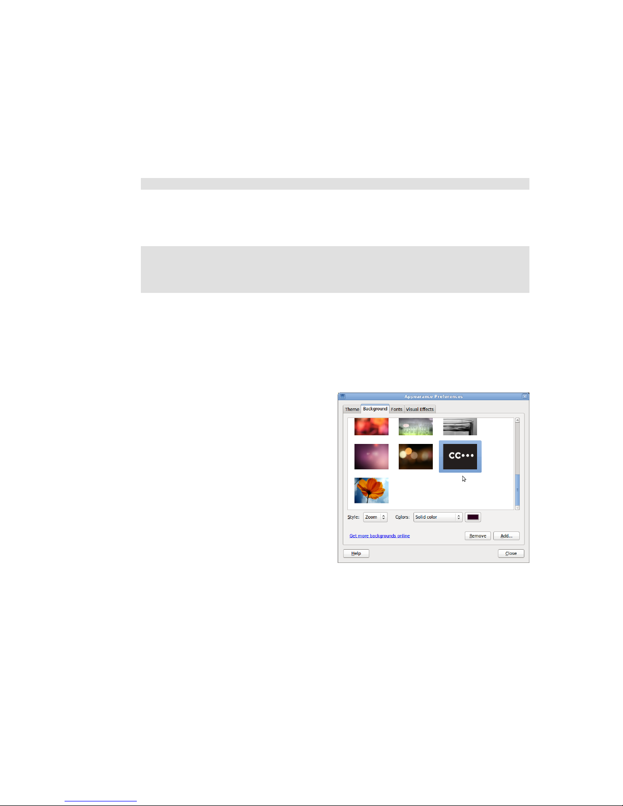
8.9. Desktop background image replacement
The desktop image that is shown as default image
can be replaced. Follow these steps to replace it with
an image of your own:
Restart the system into rescue mode and then open
the menu System > preferences > Appearance. Use
the configuration menu to replace the desktop
image. Make sure the replacement image is made
available on target device.
Choose your sample image as desired from the
Background tab. Once configured, reboot the device
into normal mode again.
8.10. USB memory installer
If a USB memory is inserted during start up, it is possible to activate a run time hook to enable
automatic software execution. For instance, this function is suitable for production time installers,
or automated SW updates.
If you add a script (executable file) that’s called autorun (only that) in the root of a USB memory,
it will be executed during device startup. The USB memory can be a FAT-formatted one or with
other suitable file system, so there is no specific requirement there.
Page 34

CCpilot XM and CrossCore XM - Software guide
Revision: 1.6
Software Guide
Date: Jun 24, 13
www.maximatecc.com
9. Windows system specifics
This section describes specific details for system running Windows. The XM Windows images are
adapted with additional drivers and software to access XM device specific hardware and
functionality.
9.1. Windows system content
To preserve file system size the Windows images have a limited set of components. For example,
only the English language support is pre-installed. Customer specific images may be created if
specific software or component configuration is needed.
9.1.1. Windows drivers
Dated 2012-03-01, the Windows driver content is as follows, i.e. this specifies the 3rd party software
that is used in XM device:
Usage
XM
Version
Provider
Driver
Audio
Win XP
Cirrus Logic
CS4207_WinXP_1-0-0-38
Win 7
CS4207_WinVista_Win7_32-64-bit_6-6001-1-30
Chipset
All
Intel
Intel_Inf_Update_Utility_AllOS_v8.8.0.1014
Ethernet
Win 7
Intel
Intel® PROSet 16.8.1
Win XP
Intel
Intel® PROSet 16.8.1
Graphic
Win 7
Intel
Intel Graphics Media Accelerator 500 Driver Release 5.0.0.2030
Win XP
Intel
Intel_GMA500_Graphics_Media_Accelerator_WinXP_v3.3.0
Jida
All
Kontron
JIDA32_Win_R118
Virtual
COM
All
Future
Technology
Devices
International
CDM20814_WHQL_Certified
9.2. File system layout
The default file system is NTFS and the compact flash is set up with one partition C:\.
9.3. Installing new drivers, applications and system packages
When installing third party software use the installation guidelines provided by the software
provider.
9.4. Remote access
There are a couple of remote access software programs installed in the XM device with Windows.
Those are SSH server, VNC server and serial number broadcaster service.
9.4.1. SSH
It is possible to connect to the XM device with SSH access even when its operating system is
Windows. This provides a means to remote copy files to the XM device over the network in analogy
to how it’s done with the Linux system. It also provides terminal access to the Windows system
from a remote location.
Page 35
CCpilot XM and CrossCore XM - Software guide
Revision: 1.6
Software Guide
Date: Jun 24, 13
www.maximatecc.com
9.4.2. VNC
The XM device also has a VNC server enabled, so that the GUI desktop can be accessed remotely,
for instance when using CrossCore XM headless devices. The VNC server requires a password, and
it’s set to “default”.
To access the device via VNC, you will need to use a VCN viewer application and enter the IP
address of the XM device, along with the password when prompted for.
9.4.3. Serial Number Broadcaster
The XM device Windows version can identify itself over the IP network by sending out its serial
number as a broadcast IP packet. The CCSnbService service is started by default at device boot-up
and will broadcast a specific identification message to the local network every fifth second. This
service is part of the CC AUX installation package, and can be disables as any normal operating
system service.
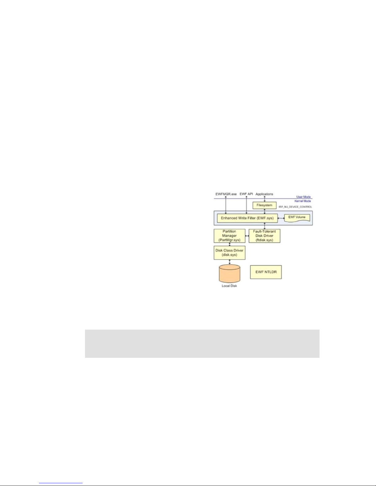
9.5. Embedded write filter
The maximatecc Windows Embedded 7 (WES7) image
uses the Embedded Write Filter (EWF) to reduce wear
on the compact flash disk.
EWF is primarily intended to write protect a run-time
image. For Compact flash based devices it can also be
used to extend the lifespan of the media by limiting
the number of disk writes. In WES7, EWF can work
only in RAM mode. This means that EWF works as a
RAM overlay enabling the OS to act as normal, but no
changes are committed to disk until the user triggers a
commit. EWF commits includes all changes to the
partition.
Follow these steps to enable EWF RAM reg mode on a partition:
1. Enabl e E W F on p a rt it io n:
> e w f m g r < p ar t it io n> -ena b l e
e. g . > e wf mg r C : -enabl e
2. Reboo t f o r EW F se tting s t o t ak e ef f e ct.
Please refer to the Microsoft EWF documentation, [6], for more information on how to set up and
use EWF.
9.6. File based write filter
In addition to the Embedded Write Filter, maximatecc Windows Embedded 7 (WES7) image also
includes File Based Write Filter (FBWF).
One disadvantage with EWF is that it only works on a sector level and is unaware of the file
structure which makes it hard to implement single file commits. Therefore a file based write filter is
available which operates on a file level. Using FBWF you can set up a list of write through files
which are persistent and keep the rest in the RAM overlay reducing the number of writes to disk.
Page 36

CCpilot XM and CrossCore XM - Software guide
Revision: 1.6
Software Guide
Date: Jun 24, 13
www.maximatecc.com
Using FBWF it is also possible to perform file level commits. The normal usage scenario for EWF
and FBWF is that EWF is used to protect the partition with the run-time image and FBWF is used
on a data partition to enable file operations.
Follow these steps to enable FBWF on a WES7 image:
1. E n a b le F BW F
>fbwfm g r . e x e / en a b le
2. A d d a v o lu m e to p r ot ec t
>f b w m g r . ex e / a dd vo lu m e C:
3. A d d a d i re c to ry t o e xc lu d e ( ad d to w rite - t hr o ug h li s t )
>f b w m g r . ex e / a dd ex cl usion C : \ Pe r s on al
4. C h e c k t h e s ta tu s
>f b w m g r . ex e
5. R e b o o t f or ch an ge s t o oc c ur .
Please refer to the Microsoft FBWF documentation, [7], on how to set up and use FBWF.
9.7. Hibernate once resume many
Hibernate once resume many (HORM) is a feature available in the maximatecc Windows
Embedded 7 (WES7) image.
HORM enables a robust boot scenario using a one-time created hibernation file from which the
system always boots. This enables the creation of very fast booting as well as robust devices. Even
after power failures these systems come up quick and without damages to the file system. HORM
requires RAM or RAM (Reg) overlay and can only be configured using EWF. HORM can be
activated and deactivated using a command line tool. HORM has a requirement that all volumes
must either be protected with EWF or be in unmounted state when the Hibernate Once occurs. This
is to prevent state synchronization problems. Each Resume from hibernation expects the entire
system to be in exactly the same state as when the Hibernate Once occurred.
Follow these steps to enable HORM on a WES7 image:
1. Enabl e h i b e rn at i on
> p o w e r c fg . ex e / h ON
2. Disab l e f a l se b o ot st at w a r ni ng s
> b c d e d i t. e xe /s et { c ur re nt } b o ot st at u s polic y i g n o re a l lf ai lu re s
3. Enabl e E W F on a l l pa rt it i o ns
> e w f m g r .e x e / al l /enab l e
4. Resta r t t o ha ve th e co mm a n d ta ke ef f ect
> s h u t d o wn . ex e / r /t 0
5. Activ a t e H O RM
> e w f m g r .e x e C : /a ct i va te ho r m
6. Captu r e t h e H OR M s ta te b y hi be rn a ti n g the m a c h i ne o nc e
> s h u t d o wn . ex e /h
7. Resum e t h e ma ch i ne a nd s t a rt u si n g H ORM. A t t h i s p o i n t e ac h
re s t a r t sh o ul d r es ul t i n a r es u me f ro m the s t a t e c ap t u re d in
th e p r e v io u s s te p
8. To ch a n g e t he h i be rn at io n fi le s t at e you s i m p l y s e t t he
co m p u t e r i n t h e st at e y ou w a nt (s ta rt a pplic a t i o n s e t c .) , pr es s
WI N + R a n d e xe c ut e co m ma nd “ s hu t do wn –h” t o c re at e a ne w
hi b e r n a t io n f i le .
Please refer to the Microsoft HORM documentation, [8], on how to set up and use HORM.
Page 37

CCpilot XM and CrossCore XM - Software guide
Revision: 1.6
Software Guide
Date: Jun 24, 13
www.maximatecc.com
Operating system licensing
OS
OS Version
Licensing
Linux
Ubuntu LTS
Derivate
Ubuntu is distributed under the GNU General Public License (GPL)
licence. http://www.ubuntu.com/
Windows
Microsoft Windows
Embedded
Standard 7
maximatecc’s standard WES7 image for XM device requires the WS7P
SKU (licence); the tablet PC package included in the image requires this
license. www.microsoft.com/windowsembedded
Windows
Microsoft Windows
XP Tablet PC
Edition
maximatecc’s Windows XP Tablet PC edition image for XM device
requires a Windows XP Pro for embedded systems licence.
Windows
Microsoft Windows
XP Embedded
maximatecc does not provide a standard Windows XP image, but a
board Support Package is available for XM device. A Windows XP
Embedded license is required.
For specific versions of 3rd party software, please see each operating systems system contents
chapter above.
Page 38

CCpilot XM and CrossCore XM - Software guide
Revision: 1.6
Software Guide
Date: Jun 24, 13
www.maximatecc.com
Technical support
Contact your reseller or supplier for help with possible problems with your XM device. In order to
get the best help, you should have access to your XM device and be prepared with the following
information before you contact support.
The part number and serial number of the device, which you find on the brand label.
Date of purchase, which is found on the invoice.
The conditions and circumstances under which the problem arises.
LED indicator flash patterns.
Prepare a system report on the device, from within CCsettings (if possible).
Detailed description of all external equipment connected to the unit (when relevant to the
problem).
Trade Mark, etc.
© 2012 CrossControl AB
All trademarks sighted in this document are the property of their respective owners.
CCpilot is a trademark which is the property of CrossControl AB.
Intel is a registered trademark which is the property of Intel Corporation in the USA and/or other
countries. Linux is a registered trademark of Linus Torvalds. Microsoft and Windows are registered
trademarks which belong to Microsoft Corporation in the USA and/or other countries.
CrossControl AB is not responsible for editing errors, technical errors or for material which has
been omitted in this document. CrossControl is not responsible for unintentional damage or for
damage which occurs as a result of supplying, handling or using of this material including the
devices and software referred to herein. The information in this handbook is supplied without any
guarantees and can change without prior notification.
CrossControl respects the intellectual property of others, and we ask our users to do the same.
Where software based on CrossControl software or products is distributed, the software may only
be distributed in accordance with the terms and conditions provided by the reproduced licensors.
For end-user license agreements (EULAs), copyright notices, conditions, and disclaimers,
regarding certain third-party components used in the XM device, refer to the copyright notices
documentation.
 Loading...