

maximal FD80T, FD100T, FD50-70T MWF, FD50-70T MWH, FD50-70T MGH Maintenance Manual
...
5-10t Internal Combustion Counterbalance Forklift Truck Operation & Maintenance Manual
-1-
Introduction
This manual has mainly introduced the items related to performance, structure, operation,
maintenance, as well as service, and other aspects of M portfolio 5-10t forklift trucks, in order
for operators to understand the forklift trucks, and to use and maintain the trucks correctly.
During the application of forklift trucks, user’s operators and equipment management
personnel involved shall carefully observe the requirements and specifications for forklift
trucks in this manual, for the forklift trucks to regularly maintain a good technical condition.
Due to our continuous improvement of the forklift truck products, the items of this manual are
subject to alteration and may vary slightly from the real forklift trucks without prior notice,
for which your kind understanding is expected.
Note: The type code in this manual is different from the model on product data plate and
certificate of conformity. The type code of this series of trucks has covered engine and its
modification code.
Example:
FD50T — M W F
Isuzu 6BG1 Engine
Imported
Maximal
Model

5-10t Internal Combustion Counterbalance Forklift Truck Operation & Maintenance Manual
-2-
Table of Contents
Introduction............................................................................................................................................... 1
Table of Contents......................................................................................................................................1
I. Safety Rule for Drive and Operation of Forklift Truck.................................................................. 4
II. Main Technical Parameters for Forklift Truck..............................................................................12
III. Introduction for Main Parts of Forklift Truck .............................................................................15
IV. Structure, Principle, Adjustment, and Maintenance of Forklift Truck....................................17
1. Power System.......................................................................................................................................18
1.1 Overview............................................................................................................................................. 18
1.2 Engine Configuration ....................................................................................................................... 18
1.3 Fuel System ........................................................................................................................................21
1.3.1 Fuel Tank .........................................................................................................................................22
1.3.2 Fuel Sensor Device........................................................................................................................22
1.3.3 Fuel Filter ........................................................................................................................................23
1.4 Cooling System.................................................................................................................................. 23
1.5 Examination and Adjustment..........................................................................................................23
1.5.1 Air Filter...........................................................................................................................................24
1.5.2 Fuel Filter.........................................................................................................................................24
1.5.3 Engine Oil Filter.............................................................................................................................25
1.5.4 Cooling System .............................................................................................................................. 25
1.5.5 Fastening of Bolts for Engine Cylinder Head..........................................................................26
1.5.6 Adjustment of Valve Clearance................................................................................................... 27
1.5.7 Confirmation of Ignition Time for Fuel Injection ...................................................................28
1.5.8 Adjustment of Ignition Time for Fuel Injection....................................................................... 29
1.5.9 Determination of Compression Pressure...................................................................................29
1.5.10 Exhaust of Injection Pump.........................................................................................................29
2. Electrical System .................................................................................................................................30
2.1 Overview............................................................................................................................................. 30
2.2 Brief Introduction about Operation ...............................................................................................35
2.3 Battery..................................................................................................................................................38
2.4 Wire Harness ...................................................................................................................................... 38
3. Transmission Device........................................................................................................................... 39
3.1 Overview............................................................................................................................................. 41
3.2 Torque Converter............................................................................................................................... 41
3.3 Oil Feed Pump ................................................................................................................................... 43
3.4 Hydraulic Clutch ...............................................................................................................................43
3.5 Control Valve and Inching Valve....................................................................................................45
3.6 Oil Circult System for Torque Converter .....................................................................................46
3.7 Notices during Failure Occurrence with Forklift Truck............................................................48
3.8 Failure Removal ................................................................................................................................48
4. Drive Axle .............................................................................................................................................55
4.1 Overview............................................................................................................................................. 55
4.2 Speed Differential..............................................................................................................................55
4.3 Wheel-sided Reducer........................................................................................................................58

5-10t Internal Combustion Counterbalance Forklift Truck Operation & Maintenance Manual
-3-
4.4 Failure Removal ................................................................................................................................60
4.5 Maintenace Data................................................................................................................................ 61
5. Brake System........................................................................................................................................62
5.1 Overview............................................................................................................................................. 63
5.2 Power Brake .......................................................................................................................................64
5.2.1 Brake Pedal Device .......................................................................................................................64
5.2.2 Brake Valve .....................................................................................................................................67
5.2.3 Energy Accumulator......................................................................................................................68
5.3 Vacuum Power Brake .......................................................................................................................70
5.3.1 Vacuum Booster and Brake Master Cylinder........................................................................... 70
5.3.2 Method for Installation of Vacuum Booster and Brake Master Cylinder Assembly........73
5.3.3 User Notices....................................................................................................................................74
5.3.4 Failure and Cause Analysis..........................................................................................................74
5.4 Wheel Brake.......................................................................................................................................74
5.4.1 Wheel Brake (For 5-7t Trucks)................................................................................................... 75
5.4.2 Wheel Brake (For 8-10t Trucks).................................................................................................78
5.5 Parking Brake.....................................................................................................................................78
5.6 Failure Removal ................................................................................................................................81
6. Steering System....................................................................................................................................82
6.1 Steering Unit.......................................................................................................................................84
6.1.1 Overview..........................................................................................................................................84
6.1.2 Operating Principle........................................................................................................................85
6.1.3 Application Requirements............................................................................................................ 86
6.1.4 Examination and Maintenance of Steering Unit......................................................................87
6.1.5 Failure and Removal for Steering Unit...................................................................................... 89
6.2 Examination after Reassembly of Steering System: ..................................................................91
6.3 Failure Removal for Steering System ...........................................................................................93
6.4 Steering Axle ......................................................................................................................................93
6.4.1 Steering Axle Body........................................................................................................................93
6.4.2 Left-Right Steering Knuckle Assembly.....................................................................................93
6.4.3 Wheel Hub.......................................................................................................................................94
6.4.4 Steering Cylinder ...........................................................................................................................94
7. Hydraulic System ................................................................................................................................96
7.1 Overview............................................................................................................................................. 97
7.2 Oil Pump ............................................................................................................................................. 97
7.3 Multi-way Valve ................................................................................................................................ 97
7.4 Operation of Multi-way Valve ........................................................................................................98
7.5 Work of Main Safety Valve .............................................................................................................99
7.6 Work of Tilt Auto-locking Valve ..................................................................................................100
7.7 Control Device of Multi-way Valve ............................................................................................100
7.8 Oil Tank............................................................................................................................................. 100
7.9 Oil Circuit of Hydraulic System...................................................................................................101
7.10 Maintenance ...................................................................................................................................104
7.10.1 Disassembly of Multi-way Valve ...........................................................................................104

5-10t Internal Combustion Counterbalance Forklift Truck Operation & Maintenance Manual
-4-
7.10.2 Reassembly of Multi-way Valve.............................................................................................104
7.10.3 Notices ......................................................................................................................................... 105
8. Lift Cylinder and Tilt Cylinder .......................................................................................................105
8.1 Lift Cylinder.....................................................................................................................................105
8.2 Isolating Valve..................................................................................................................................108
8.3 Limiting Valve..................................................................................................................................108
8.4 Tilt Cylinder...................................................................................................................................... 110
9. Lifting System.................................................................................................................................... 111
9.1 Overview........................................................................................................................................... 112
9.2 Outer & Inner Mast......................................................................................................................... 112
9.3 Fork Carriage.................................................................................................................................... 112
9.4 Adjustment of Lifting System....................................................................................................... 112
9.4.1 Gasket Adjustment for Lift Cylinder Head............................................................................. 112
9.4.2 Height Adjustment for Fork Carriage ......................................................................................113
9.5 Mounting Positions of Rollers...................................................................................................... 114

5-10t Internal Combustion Counterbalance Forklift Truck Operation & Maintenance Manual
-5-
I. Safety Rule for Drive and Operation of Forklift Truck
I. The drivers and management personnel of forklift truck must bear in mind “Safety First”,
and conduct safety operation and standard operation according to the “Operation and
Maintenance Manual” for the forklift truck.
II. Conveyance of Forklift Truck
It is required to pay attention to the following items when motor vehicle is used to load and
convey the forklift truck.
1. Skid the parking brake.
2. Both the front and rear parts of mast and counterweight shall be properly fixed using steel
wire. The corresponding positions of front and rear tyres shall be firmly wedged up using
wedge blocks.
3. The forklift truck shall be listed according to the marked position on the “Lift Data Plate”
for forklift truck at the lifting time.
III. Storage of Forklift Truck
1. Drain the fuel completely (It is not to be drained if coolant is the antirust and antifreeze
fluid.)
2. Coat the surface of unpainted parts with antirust oil, and coat the lift chain with lubricating
oil.
3. Drop the mast to the lowest position.
4. Skid the parking brake.
5. Wedge up the front and rear tyres properly using wedge blocks.
IV. Preparation prior to Use
1. Avoid examining fuel, oil leak, oil level, and examining electrical instrument in a place
with an open fire, and avoid adding fuel during operation.
2. Examine the air pressure of tyres.
3. It is required to place the handle for forward/backward gear at the middle position (zero
gear position).
4. Don’t smoke when fuel system is working and when battery is being examined.
5. Examine the status of respective handles and pedals.
6. Get properly prepared for startup.
7. Loosen the parking brake.
8. Perform the test actions such as rise and fall of mast, forward and backward tip, steering,
and brake.
V. Operation of Forklift Truck

5-10t Internal Combustion Counterbalance Forklift Truck Operation & Maintenance Manual
-6-
1. Only the drivers who have been trained and hold driving license are allowed to drive the
truck.
2. The operators shall wear shoes, helmet, clothes, and gloves that can be used for safety
protection.
3. Examine respective controls and warning devices before truck is driven, and the truck shall
be operated after it has been repaired in the case when any damage or defect is found.
4. During conveyance, the load shall not exceed the specified value, the fork must be
completely inserted into the underside of cargo, and the cargo must be uniformly placed on
the fork. It is not allowed to pick up cargo using a single fork tip.
5. Smoothly perform start, steering, running, brake, and, and slow down at turning, on wet or
smooth pavements.
6. It is required to place cargo as low as possible, and to keep the mast tilt backwards, when
cargo is loaded for driving.
7. It is required to be careful during driving on a ramp. It is required to drive forward during
upgrade and drive reversely during downgrade, when the truck is driven on a ramp larger than
1/10. Turning shall be avoided by all means, and please never perform loading-unloading
operation when forklift truck is running downgrade.
8. It is required to pay attention to passengers, obstacles, and low-lying pavements, and pay
attention to the clearance above the forklift truck, during driving.
9. It is not allowed for anyone to stand on fork and it is not allowed for anyone to be carried
on truck.
10. It is not allowed for anyone to stand under the fork, or to walk under the fork.
11. It is not allowed to control the truck and attachments at any position other than the driver
seat.
12. It is required to pay attention to the fall of cargo from above, for any high lift forklift
trucks with a lifting height larger than 3m, and protective measures must be taken, when
necessary.
13. Try as much as possible to tip backward the mast for high-lift forklift trucks during work,
and it is required to perform front or back tip within the minimum range during
loading-unloading operation.
14. It is required to take a doubled care, and to drive slowly, during running on dock or on
temporary planks.
15. Driver shall not stay on the truck, when fuel is added, and the engine shall be turned off.
Ignition is to be avoided when battery or level of oil tank is examined.

5-10t Internal Combustion Counterbalance Forklift Truck Operation & Maintenance Manual
-7-
16. The forklift trucks with attachments shall be operated as loaded forklift trucks during
unloaded operation.
17. Don’t convey unfixed or loosely stacked cargo, and take care when cargo of relatively
large size is conveyed.
18. Drop the fork onto the ground, put the handle for gear position to neutral gear, and turn off
the engine or disconnect the power supply when driver leaves the truck. Pull the parking
brake device properly when truck is parked on a ramp, while wedge blocks must be used to
fill up the wheels when the truck is to be parked there for a long time.
19. It is not allowed to open radiator cover carelessly, under the condition when engine is very
hot.
20. The pressures of multi-way valve and safety valve have been properly adjusted before
delivery of forklift truck from factory, and users shall not adjust them at discretion during use,
to avoid damage of entire hydraulic system and hydraulic components due to excessively high
adjustment.
21. The value of air pressure specified on the label plate of “Tyre Air Pressure” shall be
followed for tyre air charge.
22. The maximum noise outside the forklift truck is not to be larger than 89dB (A), and
JB/T3300 shall be followed as test method.
23. Get familiar with and pay attention to the functions of various data plates on the forklift
truck.
5-10t Internal Combustion Counterbalance Forklift Truck Operation & Maintenance Manual
-8-
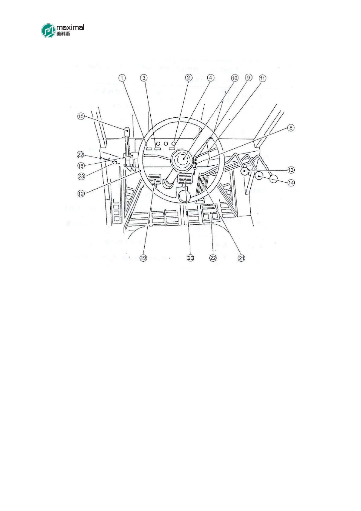
VI. Schematic Drawing of Instruments and Control Layout for Forklift Truck
1. Fuel Gage 13. Lift Handle
2. Indicator Light 14. Tilt Handle
3. Water Temperature Gauge 15. Parking Brake Handle
4. Hour Meter 16. Front-Rear-Gear Handle
8. Ignition Switch 19. Inching Pedal
9. Light Switch 20. Brake Pedal
10. Horn Pushbutton 21. Throttle Accelerator Pedal
11. Steering Light Switch 22. Engine Hood Stay Cable
12. Steering Wheel 23. Engine Stop Stay Cable
5-10t Internal Combustion Counterbalance Forklift Truck Operation & Maintenance Manual
-9-
Gasoline Engine
VII. Routine Maintenance of Forklift Truck
1. Key Points for Startup
1) Oil quantity and oil level of hydraulic oil shall be at the middle position of scale on oil
level indicator.
2) Examine whether or not leak or damage exists with pipe, joint, pump, and valve.
3) Examine wheel brake.
a) The idle stroke of brake pedal shall be 40mm.
b) The clearance between front bottom plate and pedal shall be larger than 20mm.
4) Examine the hand brake function: When hand brake handle is thoroughly pulled, it shall be
able to be skidded on a 20% ramp (no load).
5) Instruments and Illumination Light Fittings, etc: Examine whether or not the respective
parts including instruments, illumination, connection joints, switches, and electrical circuit are
working normally.
2. Oils, Greases, and Anti-freeze Fluids Used for Forklift Truck:
Original Oil
Name
Gasoline 93# or 97#
Diesel Oil
Oil (SF)
Electronic
Injection Type
(SG)
Diesel Engine
Oil (CD)
Product
Great Wall
Great Wall
Brand of Light
Diesel Oil
Application
Temperature (℃)
Viscosity Grade 5W/30 10W/40
Application
Temperature(℃)
Viscosity Grade 5W/30 10W/30
Application
Temperature(℃)
Brand, Code, and Temperature of Use
0# -10# -20# -35#
≥4 ≥-5 ≥-5~-14 ≥-14~-29
-30~
+40
-30~
+30
-25~
+40
-25~
+30
10W/30 15W/40
-25~+30 -25~+40
15W/40 20W/50
-20~+40 -15~+50
L-HM32 Antiwear
Viscosity Grade
Hydraulic Oil
Torque HAIPAI 6# Torque converter oil
Kunlun
Application
Temperature(℃)
Hydraulic Oil
>-19
L-HV32 Low Temperature
Antiwear Hydraulic oil
>-33(in Open Air in Cold
Regions)

-10-
converter oil
Brake Fluid
Lubricating
Grease
5-10t Internal Combustion Counterbalance Forklift Truck Operation & Maintenance Manual
Chongqing
4604 Synthetic Brake Fluid GB12981HZY4
Yiping
Great Wall 3# General Lithium Base Lubricating Grease(-20℃~+120℃)
Viscosity Grade 85W/90GL-5 80W/90GL-5 Heavy-duty
Truck Gear
Oil
Anti-freeze
Fluid
HAIPAI
Jinbai
Application
-15~+49 -25~+49
Temperature(℃)
Code FD-1 FD-2 FD-2A FD-3
Application
≥-25 ≥-35 ≥-45 ≥-50
Temperature(℃)

5-10t Internal Combustion Counterbalance Forklift Truck Operation & Maintenance Manual
-11-
3. Notices for Operation of Cooling System
1) When forklift truck is being operated, in the case when radiator is overheated or
temperature of coolant is excessively high, don’t open the radiator cover immediately.
Examine the liquid level, in order to find the overheating cause. When cover has to be opened,
it is required to slow down the engine to a medium speed. Turn the radiator cover slowly and
loosen off the cover after waiting for a while, to avoid scald of operator by splash of coolant.
Make sure to screw the radiator cover properly in place, when it is tightened up, and
otherwise it is difficult to build up a specified pressure system.
2) There is a feeding tank on the left side of engine, with the marks of FULL and LOW
labeled in the upper and lower parts of the tank wall, and the level of anti-freeze fluid shall be
between these two countermarks during use. Antirust and anti-freeze fluid of the same model
shall be supplied after anti-freeze fluid is leaked out or evaporated. Anti-freezing fluid is
generally used both in winter and summer, not changed for four seasons. It shall be drained
out for filtration and purification treatment after use for one year in general, to be then further
used.
3)According to different work conditions, the smudge on the outer surface of radiator shall be
periodically cleaned and removed, either to be soak cleaned using detergent, or to be flushed
using compressed air or high-pressure water (pressure not larger than 4kg/cm).
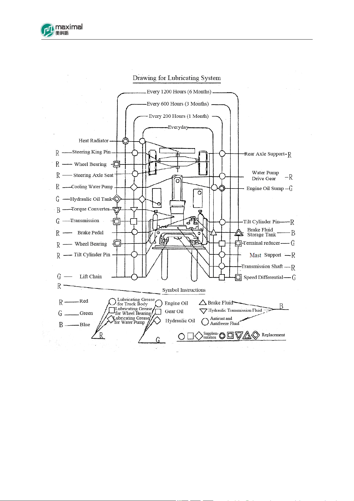
4. Drawing of Lubricating System
5-10t Internal Combustion Counterbalance Forklift Truck Operation & Maintenance Manual
-12-
5-10t Internal Combustion Counterbalance Forklift Truck Operation & Maintenance Manual
-13-
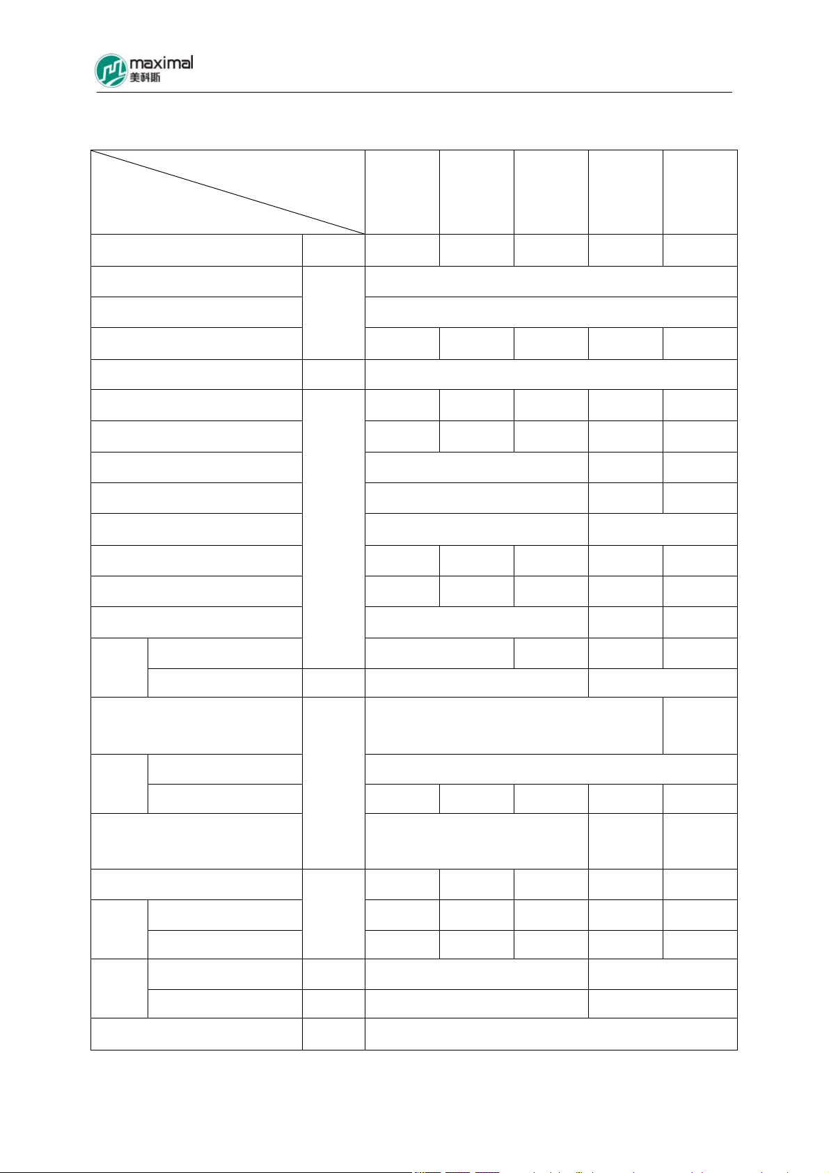
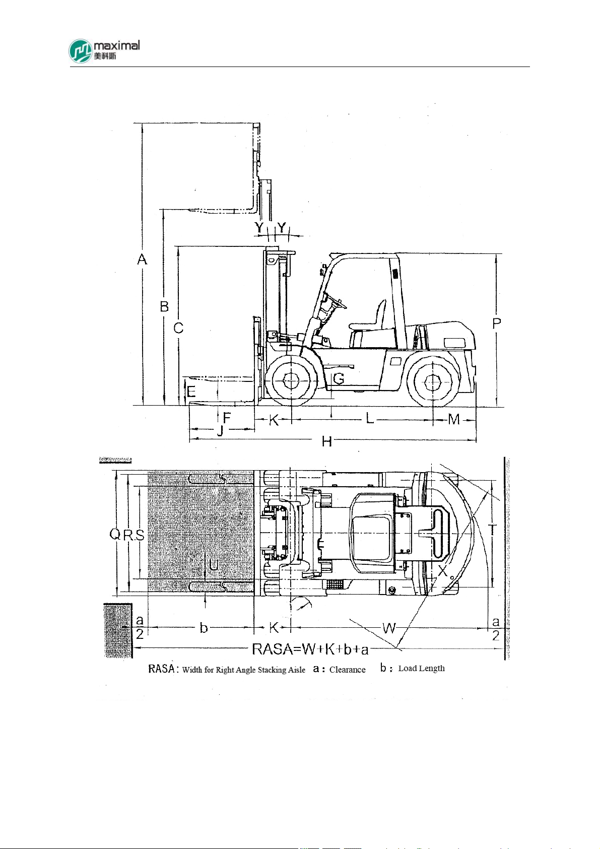
II. Main Technical Parameters for Forklift Truck
Forklift Truck
Lifting Capacity
5t 6t 7t 8t 10t
Parameter
Rated Load-lifting Capacity kg 5000 6000 7000 8000 10000
Load Center Distance 600
Max Lifting Height (Standard) B
Free Lifting Height (Standard) E
mm
195 200 205 200 210
3000
Mast Tip Angle Y/Y (º)/( º) 6/12
Min Turning Radius W 3250 3300 3370 3700 3900
Min Right Angle Aisle Width X 2960 3000 3040 3310 3540
Min Off-ground Clearance G 200 250 245
Wheelbase L 2250 2500 2800
Tread Front/Rear S/T 1470/1700 1600/1700
mm
Clearance Front/Rear K/M 590/600 590/675 590/740 700/740 718/740
Whole Length H 4660 4735 4800 5160 5480
Entire Length Q 1995 2165 2245
Height
Mast C
Overhead Guard P mm 2450 2585
2500 2625 2700 2850 Whole
Height at Rise of Fork (with Cargo
4420 4330
Stop Frame) A
Length J 1220
Fork
mm
Width×Thickness F 150×55 150×60 150×65 170×70 175×80
Fork Adjusting Range (Outer
300-1700 340-1944 410-2140
Side of Fork) R
Forklift Truck Dead Weight 8080 8740 9450 11660 12610
kg
4010/3970 3880/4760 3860/5490 4840/6120 5700/6810
Load
Full Load Front/Rear 11660/1320 13050/1590 14570/1780 17000/1950 20380/2130 Axle
No-Load Front/Rear
Front 4 8.25-15-14PR 9.00-20-14PR
Tyre
Rear 2 8.25-15-14PR 9.00-20-14PR
Batte4ry Voltage/Capacity V/Ah 24/80
5-10t Internal Combustion Counterbalance Forklift Truck Operation & Maintenance Manual
-14-
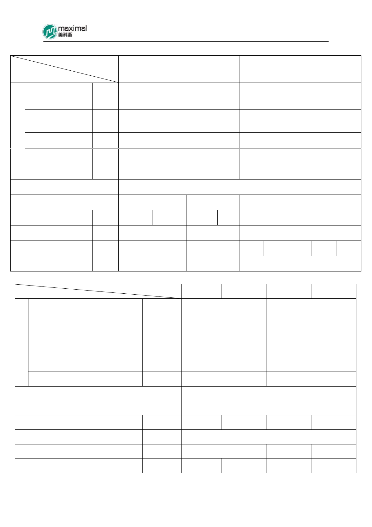
Vehicle Type
Parameter
Model
Number of Cylinders
Engine
–Diameter of Cylinder
mm 6-105×125 6-102×118 6-94×120 4-105×127
× Stroke
Rated Power/Rotating
Speed
Max Torque/Rotating
Speed
Min Fuel
Consumption Rate
Kw/rp
m
Nm/rp
m
g/kwh
Number of Transmission Shift Gears
Front/Rear
Wheel Brake Mode Power Brake
Lifting Speed Full
Load/No-Load
Max Running Speed Full
Load/No Load
Max Gradeability Full
Load/No Load
Max Traction Capacity Full
Load
Mm/s 460/500 380/420 400/600
Km/h
% 35/19 32/19 30/19
KN 54 53 53 52 45 54
FD50-70T
MWF
Isuzu (Diesel)
A-6BG1QC
FD50-70T
MGH
Chaochai
6102BG
FD50-60T
MWJ
Mitsubishi
(Diesel)
S6S-T
FD50-70T
MWH
Perkins
1104D-44TA
82.3/2000 81/2500 67.6/2300 83/2300
416/1400-1600 353/1650 293/1700 418/1400
233 231 265 245
2/2 Power Gear Shift
Vacuum Power or
Power Brake
400/6
00
Power Brake Power Brake
390/500 460/500 380/420
26/28 26/28 26/28 26/28
20/15 26/23 22/20 35/19 32/19 32/119
Vehicle Type
Parameter
Model Isuzu A-6BG1QC (Diesel)
Number of Cylinders – Diameter of
Engine
Cylinder x Stroke
mm 6-105×125 6-102×118
Rated Power/Rotating Speed Kw/rpm 82.3/2000 81/2500
Max Torque/Rotating Speed Nm/rpm 416/1400-1600 353/1650
Min Fuel Consumption Rate g/kwh 233 231
Number of Transmission Shift Gears Front/Rear 2/2 Power Gear Shift
Wheel Brake Mode Power Brake – Pedal Type
Lifting Speed Full Load/No-Load mm/s 380/410 310/350 390/480 310/390
Max Running Speed Full Load/No-Load km/h 26/30
Max Gradeability Full Load/No-Load % 21/21 21/21 20/15
FD80T FD100T FD80T FD100T
Chaochai 6102BG
Max Traction Capacity Full Load KN 63.2 58 51 57
5-10t Internal Combustion Counterbalance Forklift Truck Operation & Maintenance Manual
-15-
5-10t Internal Combustion Counterbalance Forklift Truck Operation & Maintenance Manual
-16-
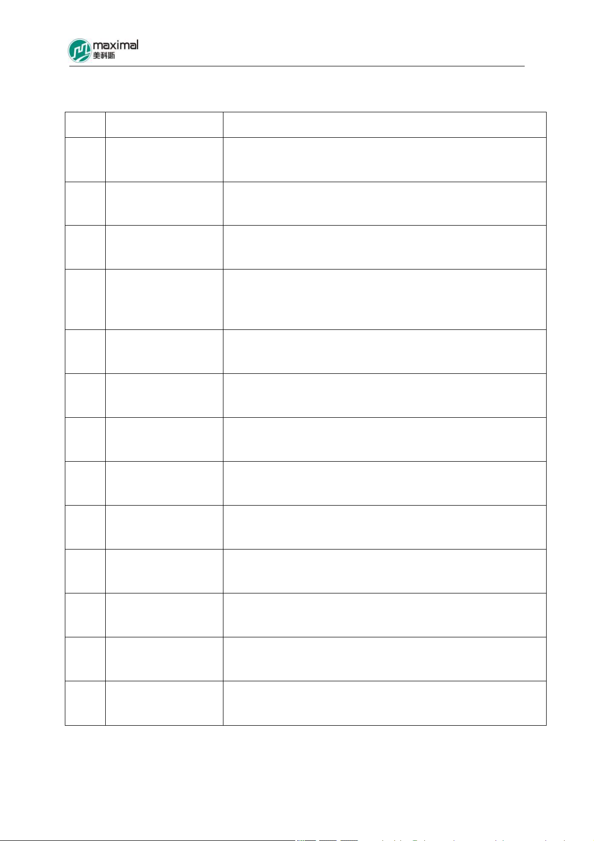
III. Introduction for Main Parts of Forklift Truck
Refer to the following table for main parts of forklift truck.
S/N Name Item
1 Air Filter and Installation Including air filter, air filter support plate, air inlet pipe, and air outlet pipe
2 Battery and Installation Including battery, cross beam, and support bar
Including radiator and standby tank, water supply and drain pipes, rubber
3 Radiator and Installation
gasket, and bolts for radiator
Fuel Device and
4
Installation
5 Muffler and Installation
6 Electrical System
Drive Axle and
7
Installation
8 Front Wheel Assembly Including tyre, front wheel rim assembly, and air valve bracket
9 Rear Wheel Assembly Including tyre, and rear-wheel rim assembly
Engine and Transmission
10
Installation
Including cover plate assembly, cover plate gasket, air plug, oil quantity
sensor, oil tank cover, oil-water separator, diesel oil filter, and oil delivery
hose
Including muffler, front vent pipe, rubber gasket, connecting pipe, vent
pipe, and U-bolt for block plate
Mainly including light fittings, instruments, wire harnesses, and electrical
components
Mainly including axle housing, transmission, speed differential,
wheel-sided reducer, half shaft, and brake
Including drive transmission, engine, transmission bracket, and
transmission support
Including bracket for control rod, pin shaft, rocking arm, and connecting
11 Transmission Control
rod
Steering Device and
12
Installation
Steering Axle and
13
Installation
Including steering column, universal joint, connecting shaft, steering
wheel, and handle
Including steering axle, and steering cylinder

5-10t Internal Combustion Counterbalance Forklift Truck Operation & Maintenance Manual
-17-
S/N Name Item
Torque Converter Oil
14
Cooling System
Overhead Guard and
15
Installation
16 Throttle Control Including pedal, connecting shaft, bracket, and stay wire
17 Hand Brake Control Including hand brake assembly
Including articulating bolts, oil filter, oil pipe, and bracket for oil filter
Including overhead guard, handle, light bracket, and air intake window
Brake and Inching
18
Control
19 Truck Frame
Counterweight and
20
Installation
Instrument Bracket and
21
Hook Installation
22 Seat and Installation Including seats, and rubber gaskets for seats
Multi-way Reversing
23
Valve Control
Mainly including brake and inching control, oil pipe, joint, energy
accumulator (or vacuum tank and vacuum booster), brake valve, and
safety valve
Including front plate, left/right truck frames, rear truck frame,
transmission bracket, bracket for tilt cylinder, engine bracket, and battery
cover plate
Including counterweight, traction bolt, and netting guard
Including instrument bracket, internal combustion engine hood, floor,
articulation, cross beam, radiator cover plate, and air spring
Including control rod, bent plate, connecting shaft, and pull rod
Working Oil Tank and
24
Installation
25 Hydraulic System
26 Working Device
Including oil suction pipe assembly, edge filter, and breathing apparatus
Mainly including gear pump, multi-way valve, hydraulic steering unit, HP
oil pipe, and joint
Mainly including mast, fork, fork carriage, cargo stop frame, lift cylinder,
tilt cylinder, lift chain, mast sprocket, and roller, etc
5-10t Internal Combustion Counterbalance Forklift Truck Operation & Maintenance Manual
-18-
IV. Structure, Principle, Adjustment, and Maintenance of Forklift Truck
1. Power System
1.1 Overview
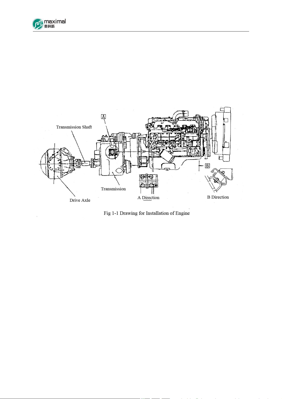
Power system mainly includes engine, fuel system, cooling system, and exhaust system.
Engine is installed on truck frame through rubber pads, to reduce vibration. Engine, torque
converter, transmission, transmission shaft, and drive axle are formed into a unit. Refer to Fig
1-1.
5-10t Internal Combustion Counterbalance Forklift Truck Operation & Maintenance Manual
-19-
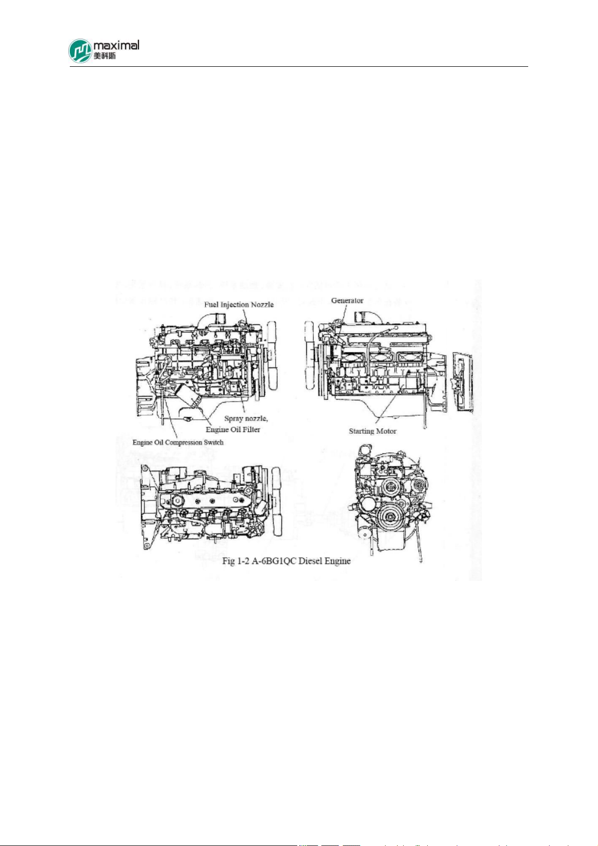
1.2 Engine Configuration
Engines for 5-7t forklift trucks mainly include imported diesel engines such as Isuzu 6BG1,
Mitsubishi S6S-T, and Perkins, and homemade diesel engines such as Chaoyang 6102BG-38.
Engines for 8-10t forklift trucks include imported diesel engine Isuzu 6BG1 and homemade
diesel engine Chaoyang 6102BG. The imported Isuzu 6BG1-model diesel engine is mainly
described here, and the others will not be described here as user may refer to the attached
operation manual for engines.
Refer to Fig 1-2 for the outside structural drawing for 6BG1, and refer to the attached Table 1
for its main performance parameters for structure and configuration.

5-10t Internal Combustion Counterbalance Forklift Truck Operation & Maintenance Manual
-20-
Name
Type
Numberof Cylinders – Cylinder Diameter ×
Stroke
Total Displacement (I)
Compression Ratio
Performance
Rated Speed(rpm)
Rated Power(kw)
Max Torque(N-m/rpm)
Fuel Consumption for Total Load (g/kwh)
Idle Speed(rpm)
Weight(㎏)
Dimension(㎜)
Ignition Sequence
Rotating Direction
Valve Gear
A-6BG1QC
4-stroke, Water-cooling, Straight-line, and top Diesel
Engine
6-105 ㎜×125 ㎜
6.494
17
2000
82.3
416/1400-1600
233
700
450
1129.5×672.0×860.0
1-5-3-6-2-4
Looking from the end of fan in clockwise direction
Top Mounted
Fuel Device
Injection Pump
Plunger Diameter x Stroke
Injection Nozzle
Oil Feed Pump
Fuel Filter
Speed Regulator
Mode of Speed Control
Lubrication Mode
Lubricating Device
Pump Type
Drive Type
Oil Pressure Adjusting Device
Oil Pressure Indicating Device
Filter Mode
Cooler
Cooling Device
Boshing Type
9.5 ㎜×8 ㎜
Multi-porous Type
Plunger Type
Paper Core of Filter Type
Centrifugal, and Full Speed Control
Forced Circulation Type
Gear Type
Camshaft Drive
Piston and Spring Type
Switch Type(0.3 ㎏/㎝2)
Full Flow and Filter Paper Type
Embedded Water Cooling Type
Cooling Mode
Cooling Fan
Drive Mode
Water Cooling
Exhaust Type, 7 Fan Blades, and Outer Diameter 550mm
Belt Drive

5-10t Internal Combustion Counterbalance Forklift Truck Operation & Maintenance Manual
-21-
Table 1 Continued
Pump Type
Drive Mode
Water Temperature Adjusting Device
Mode
Thermostat Opening Temperature
Thermostat Full Opening Temperature
Starting Motor
Mode
Voltage
Rated Power
Flameout Device
Preheating Device
Charging Generator
Mode
Voltage
Output
Vortex Type
Belt Drive
Wax Pellet Type
82℃
95℃
Magnetic Engagement Type
24V
4.5KW
Disconnecting Fuel Passage
Available
AC Generation, and Diode Rectification
24V
25A
Drive Mode
Charging Automatic Regulator
Referential Parameters
Oil Quantity in Oil Pan
Cooling Water Quantity
Valve Clearance
Suction Valve
Exhaust Valve
Valve On/Off Time
Suction Valve (Open)
(Close)
Exhaust Valve (Open)
(Close)
Injection Period
Injection Starting Pressure
Compression Pressure
Belt Drive
IC Type (Embedded in Generator
Max: 13L Min: 10L
12L
0.4 ㎜(in Cold Status)
0.4 ㎜(in Cold Status)
BTDC 19°
ABDC 47°
BBDC 57°
ATDC 15°
14° BTDC 14°
185 ㎏/㎝2
31 ㎏/㎝2(200rpm)
5-10t Internal Combustion Counterbalance Forklift Truck Operation & Maintenance Manual
-22-
1.3 Fuel System
Fuel system consists of fuel tank, filter, and fuel sensor device.
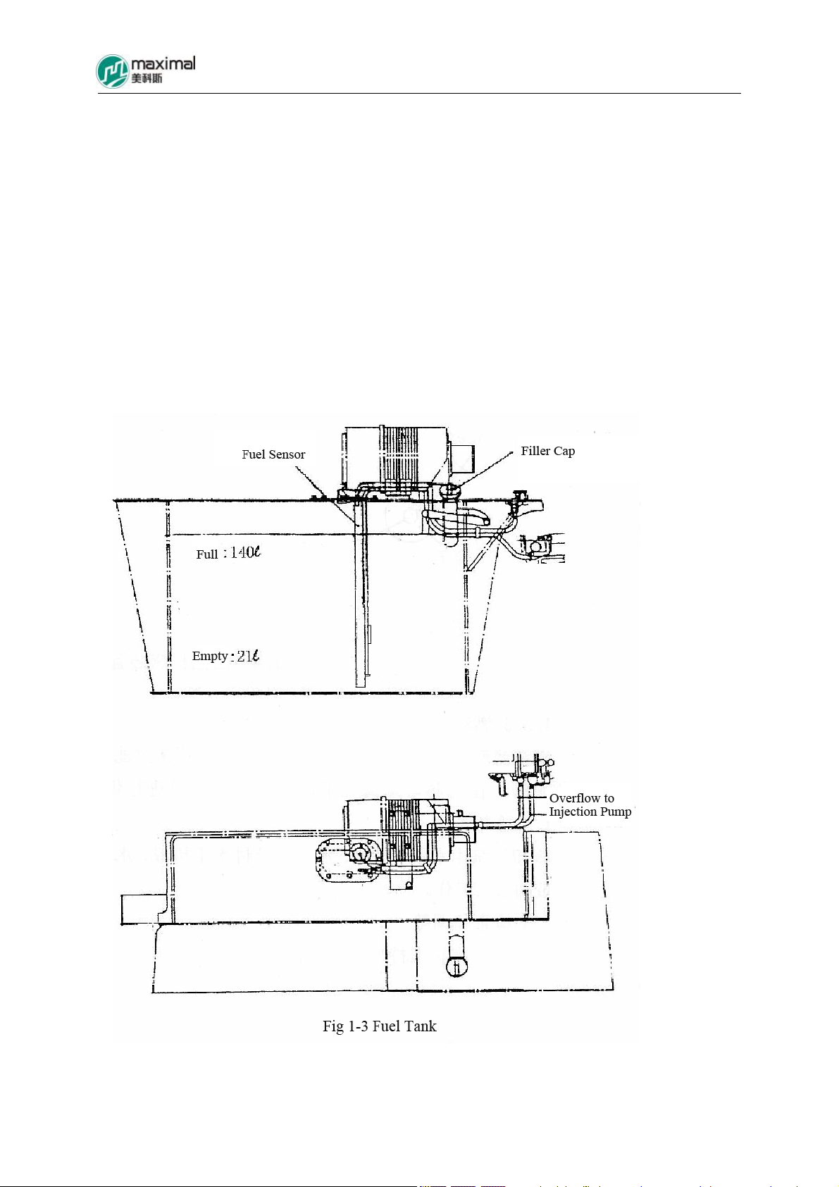
1.3.1 Fuel Tank
Fuel tank is a welded structure, connected with truck frame into a whole, mounted on the left
side of the truck frame, with fuel tank cover plate on top, and fuel sensor mounted on the plate.
Refer to Fig 1-3.
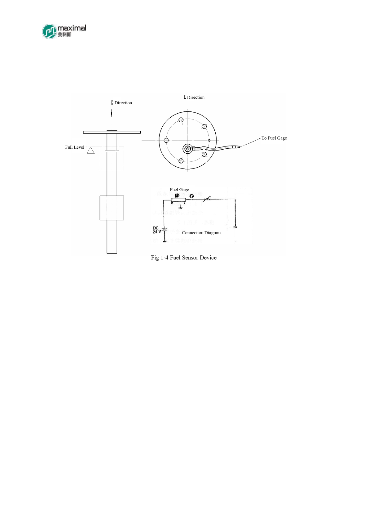
1.3.2 Fuel Sensor Device
The function of fuel sensor device is to transform the oil quantity stored in fuel tank into
current through up and down movement of float, to be ultimately responded to the fuel gage
on instrument panel, to allow people to visually understand the fuel quantity inside the fuel
tank. Refer to Fig 1-4.
5-10t Internal Combustion Counterbalance Forklift Truck Operation & Maintenance Manual
-23-
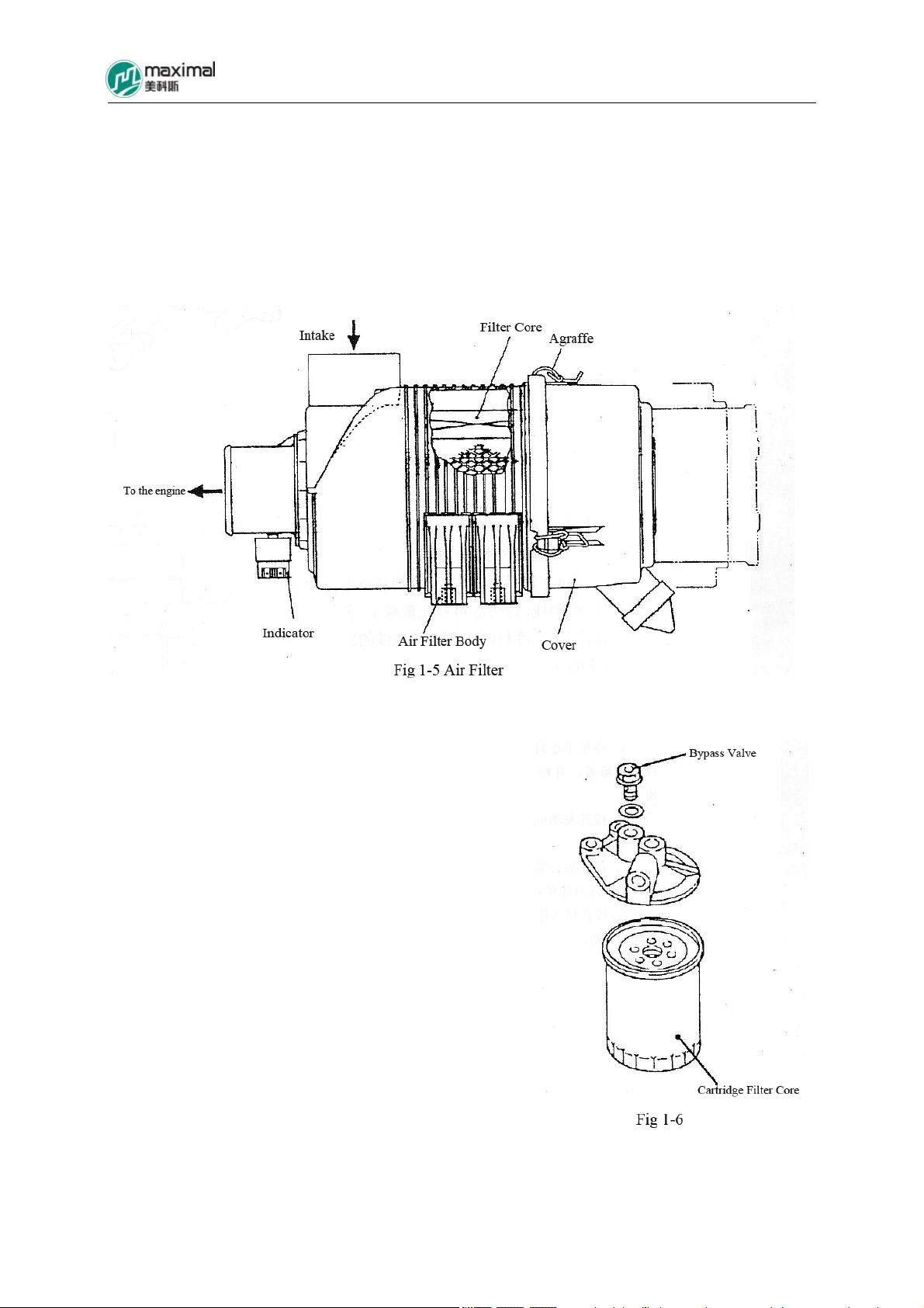
1.3.3 Fuel Filter
Fuel filter is mounted on the oil inlet manifold of engine, used to filter fuel to be supplied to
engine. Bypass valve is also mounted inside the filter, able to supply fuel to engine as well,
under the condition when core of filter is blocked.
1.4 Cooling System
Cooling system is composed of water pump, fan, radiator, and assistant radiator. Water pump
is installed on engine, and the crankshaft actuates the work of water pump through V-shaped
rubber belt.
1.5 Examination and Adjustment
In order for engine to maintain a good work status, it is required to carry out regular
examinations and adjustment to engine. The key points are given as follows:
5-10t Internal Combustion Counterbalance Forklift Truck Operation & Maintenance Manual
-24-
1.5.1 Refer to Fig 1-5 for air filter.
(1)Take out the core of filter.
(2)Examine the dust and damage status of core of filter. Firstly use low-pressure air to blow
from the inner side to the outer side, for cleaning, and the core of filter shall be replaced, if it
is severely block and cannot be cleaned or it has been damaged.
(3)Clean the dust inside the cover.
1.5.2 Refer to Fig 1-6 for fuel filter.
(1)Demount the fuel filter using special wrench, and it
shall be replaced, if damaged or blocked.
(2)Add several drips of fuel around the seal ring along
the new fuel filter and then mount it on. Further screw
it in for 2/3 circles, after seal ring has touched the
main body of fuel filter.

5-10t Internal Combustion Counterbalance Forklift Truck Operation & Maintenance Manual
-25-
1.5.3 Refer to Fig 1-7 for engine oil
filter.
(1)Detach the fuel filter using special
wrench and replace it.
(2)Fill several drips of lubricating oil
around the seal ring along the new
engine oil filter and then mount it on.
Further screw it in for 2/3 circles
after the seal ring has touched the
main body of the filter.
C
1.5.4 Cooling System
(1)Examine the coolant in the assistant radiator.
Refer to Fig 1-8 for assistant radiator, and it
indicates that the supply of radiator is reduced and
it is required to add coolant, when the level of
coolant is lower than the scale line of “LOW, and
it shall be added up to the place of 2/3 scale
between the upper and lower countermarks.
(2)Replace the coolant.
A. Open the radiator cover, after shutdown for
more than half an hour and until it has been
cooled down, and loosen the water drain valve on
the underside of radiator.
B. Loosen the water drain valve of engine, and
drain the coolant completely.
C. Tighten up the abovementioned two water
Fig 1-8
drain valves after coolant is completely drained.
D. Add the specified coolant, and examine that the liquid level of assistant radiator shall be in
the place 2/3 that of the upper and lower scale lines, after idle-speed operation for a while.
5-10t Internal Combustion Counterbalance Forklift Truck Operation & Maintenance Manual
-26-
(3)Adjust the fan belt.
The fan belt shall be tightened, if it gets loose. Refer
to Fig 1-9.
Procedure: Firstly loosen the fixed bolts B and C for
generator, and move the generator outwards. Press the
belt in the place of A with finger using a 10kg force,
and its deflection is at about 10mm. Then tighten the
bolts B and C in order.
Fig 1-9
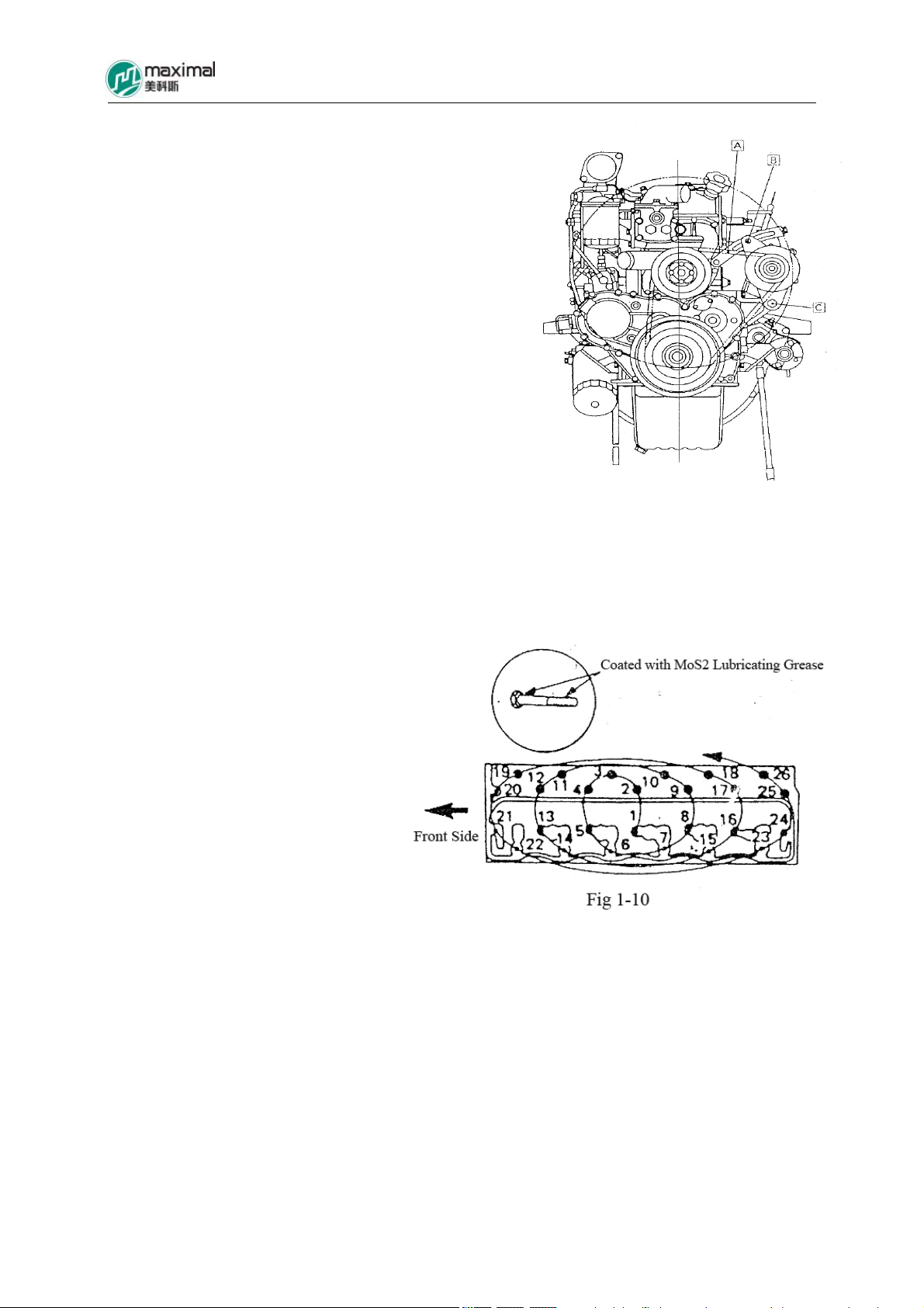
1.5.5 Fastening of Bolts for Engine
Cylinder Head
(1)Tighten the bolts for cylinder head
one by one at a 68Nm torque,
following the sequence as indicated
in Fig 1-10.
(2)Further increase the tightening
torque to 93Nm, and tighten
respective bolts one by one.
(3)Then turn respective bolts by 90°
and screw them down.
5-10t Internal Combustion Counterbalance Forklift Truck Operation & Maintenance Manual
-27-
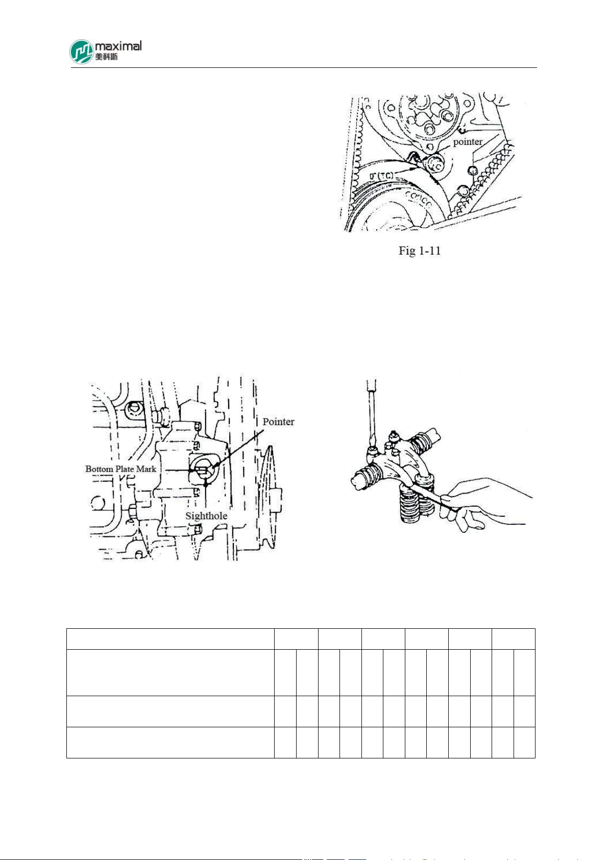
1.5.6 Adjustment of Valve Clearance
(1)Turn the crankshaft in the clockwise direction,
for the “TC” mark of belt pulley shock absorber
and the pointer to be superposed with each other.
(2)Open the inspection cover, and confirm the
positions of bottom plate mark and the pointer.
If the positions of bottom plate mark and the
pointer are consistent, it indicates upper dead
center of compression stroke for the 1st cylinder.
Adjust the valve clearance of “ ”△ countermark,
and adjust the valve clearance of “ ”※ countermark as well.
Valve Clearance Value: 0.4mm (the same value for both suction and exhaust, under the cold
status)
Refer to Figs 1-11, 1-12, and 1-13 for details.
Fig 1-12 Fig 1-13
Refer to Table 1-2 for specific adjustment.
Cylinder Sequence Number
Valve Sequence Number
I: Suction Valve
E: Exhaust Valve
Upper Center for 1st Cylinder Compression
Stroke
Upper Center for 6th Cylinder Compression
Stroke
1 2 3 4 5 6
I E I E I E I E I E I E
△ △ △ △ △ △ △
※ ※ ※ ※ ※
5-10t Internal Combustion Counterbalance Forklift Truck Operation & Maintenance Manual
-28-
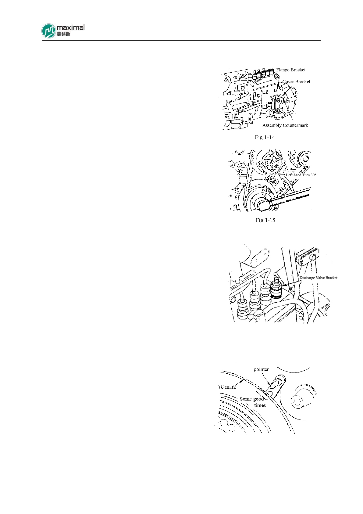
1.5.7 Confirmation of Ignition Time for Fuel Injection
(1)Firstly confirm whether or not the “Assembly
Countermark” in the place of flange for the injection
pump is consistent. Refer to Fig 1-14.
(2)Put the 1st cylinder at the position of upper dead
center for compression stroke, and turn the crankshaft
from this position in clockwise direction by about 30°.
Refer to Fig 1-15
(3)Loosen the injection pipe of the 1st cylinder, then
detach the spring and discharge valve on the bracket of
discharge valve, and then mount the bracket for
discharge valve on the fuel injection pump. Refer to Fig
1-16
(4)Slow turn the crankshaft in the clockwise direction,
at the same time while fuel feed pump is compressing
and delivering fuel, and stop turning the crankshaft
Fig 1-16
when the level of the first end for bracket of discharge
valve has risen to the stop position. Confirm the mark
of pointer symbol. Refer to Fig 1-17.
Fig 1-17
5-10t Internal Combustion Counterbalance Forklift Truck Operation & Maintenance Manual
-29-
1.5.8 Adjustment of Ignition Time for Fuel Injection
(1)Dismantle the pipe mounted on the injection pump (fuel and lubricating oil).
(2)Loosen the mounting bolts for the injection pump.
(3)Adjust towards the direction far away from engine in the “Advance” case, and adjust
towards the direction near to engine in the “Delay” case, at the same time while ignition time
is being confirmed according to the key points of 1.5.7.
(4)Tighten all the bolts assembled for injection pump, and confirm the ignition time again,
after adjustment is completed.
(5)Assemble the oil drain valve used for the first cylinder, and assemble the respective pipes
at their original separate positions.
1.5.9 Determination of Compression Pressure (Refer to Fig 1-18.)
(1)Detach the heating spark plug and injection pipes totally.
(2)Fit on the pressure gauge in the assembling part for heating spark plug of the first cylinder
(calibrated value as 500N/㎝2).
(3)Use fully charged battery to allow the rotation of starting device, and measure the pressure
at this point.
(4)Measure up to the 6th cylinder with the same method, and measure for more than two times,
respectively. Then figure out their respective average values, Compression Pressure: 304N/㎝
2
(Limit Value 255N/㎝2)
Fig 1-18
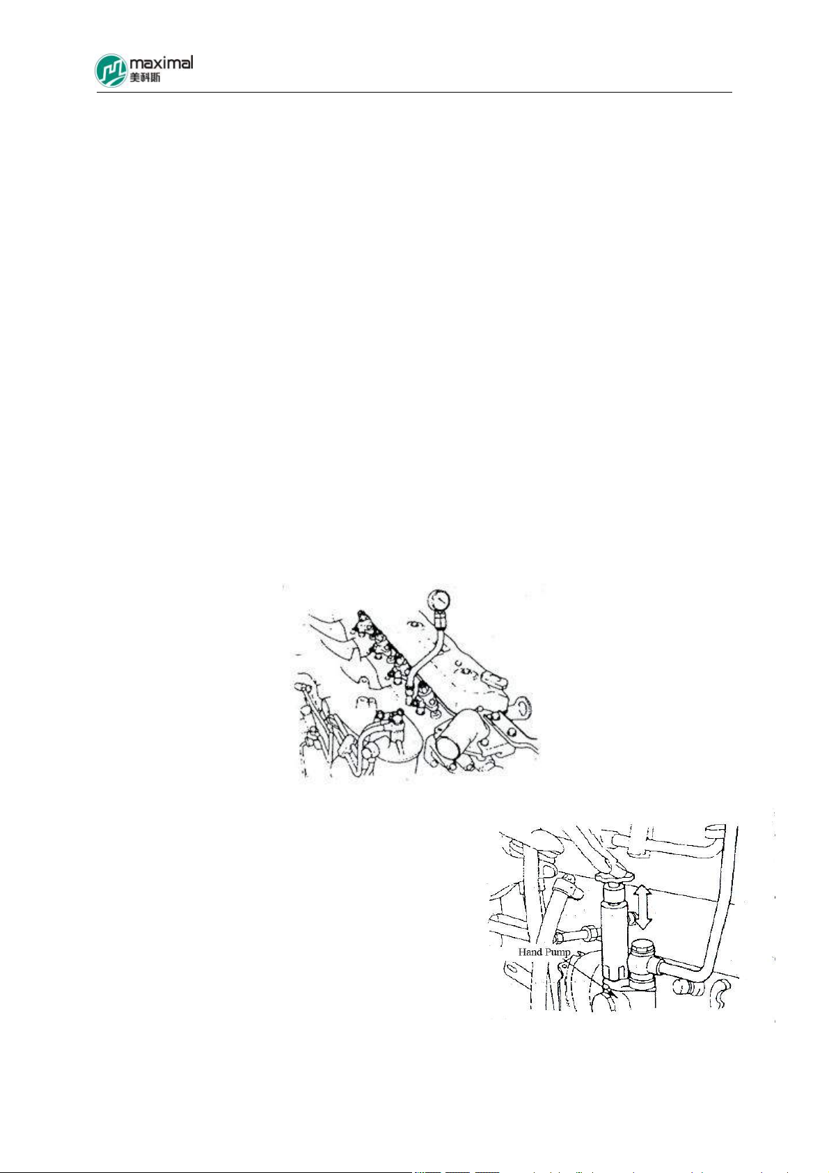
1.5.10 Exhaust of Injection Pump (Refer to Fig
1-19.)
(1)Loosen the exhaust plug for injection pump.
(2)Operate the hand pump slowly, until no air
bubble appears in the place of exhaust plug.
(3)Then tighten the exhaust plug.
Fig 1-19

5-10t Internal Combustion Counterbalance Forklift Truck Operation & Maintenance Manual
-30-
2. Electrical System
2.1 Overview
Electrical system is a negative earthed single-wire circuit. It is compared to the “Nervous
System” of forklift trucks. The electrical system is mainly composed of several units as
follows (Electrical Schematic Diagram as indicated in Fig 2-1).
1) Charging System
It is composed of generator, battery, and charging indicator light, etc, to provide the forklift
trucks with power supply for power consumers, Voltage: DC24V.
2) Starting System
It is mainly comprised of preheating system, start switch, start protective circuit, and starter,
etc, and its function is to start engine.
3) Shutdown Control System
Shutdown control system mainly consists of start switch, flameout relay, and flameout stay
wire/flameout solenoid valve, etc.
4) Instrument System
It mainly includes hour meter, and oil quantity gage, as well as charging indicator light, oil
pressure indicator light, neutral position indicator light, air filter blockage warning light, and
oil-water separator indicator light, etc, as the test equipment on forklift truck.
5) Lighting and Signal Equipment
It includes various illuminations, signal lights and horn, as well as buzzer, etc.
Front Headlight: 70W
Front Combination Light (Steering/Width) 21W/8W
Rear Combination Light (Steering/Width/Reversing/Brake): 21W(Yellow) /8W(Yellow)
/10W(White) /21W(Red)
Caution Light (Optional Part): 21W
Rear Headlight (Optional Part): 70W
License Plate Light (Optional Part): 10W
 Loading...