

Page 1

2
MOBILE COLUMN LIFT
ML-4030BC ML-6045BC ML-4034BC ML-6051BC
Installation, Operation, Maintenance Manual
IMPORTANT: READ THIS MANUAL COMPLETELY BEFORE
INSTALLING OR OPERATING YOUR LIFT
MIT Automobile Inc.
1151 West 5th Street
Azusa, California 91702
Page 2

3
OWNER / EMPLOYER OBLIGATIONS
1. The Owner/Employer shall ensure that lift operators are qualified and that they are trained in the
safe use and operation of the lift using the manufacturer’s operating instructions; ALI/SM10-1, ALI
Lifting it Right safety manual; ALI/ST-10 ALI Safety Tips card; ANSI/ALI ALOIM-2008,
American National Standard for Automotive Lifts - Safety Requirements for Operation,
Inspection and Maintenance; ALI/WL400 Series, ALI Uniform Warning Label
Decals/Placards; and in the case of frame engaging lifts, ALI/LP-GUIDE, Vehicle Lifting
Points/Quick Reference Guide for Frame Engaging Lifts.
2. The Owner/Employer shall establish procedures to periodically inspect the lift in accordance with
the lift manufacturer’s instructions or ANSI/ALI ALOIM-2008, American National Standard for
Automotive Lifts - Safety Requirements for Operation, Inspection and Maintenance; and the
Employer shall ensure that the lift inspectors are qualified and that they are adequately trained in
the inspection of the lift.
3. The Owner/Employer shall establish procedures to periodically maintain the lift in accordance with
the lift manufacturer’s instructions or ANSI/ALI ALOIM-2008, American National Standard for
Automotive Lifts - Safety Requirements for Operation, Inspection and Maintenance; and the
Employer shall ensure that the lift maintenance personnel are qualified and that they are
adequately trained in the maintenance of the lift.
4. The Owner/Employer shall maintain the periodic inspection and maintenance records
recommended by the lift manufacturer’s instructions or ANSI/ALI ALOIM-2008, American
National Standard for Automotive Lifts - Safety Requirements for Operation, Inspection and
Maintenance.
5. The Owner/Employer shall display the lift manufacturer’s operating instructions; ALI/SM 10-1, ALI
Lifting it Right safety manual; ALI/ST-10 ALI Safety Tips card; ANSI/ALI ALOIM-2008,
American National Standard for Automotive Lifts - Safety Requirements for Operation,
Inspection and Maintenance; ALI/WL Series, ALI Uniform Warning Label Decals/Placards;
and in the case of frame engaging lifts, ALI/LP- GUIDE, Vehicle Lifting Points/Quick Reference
Guide for Frame Engaging Lifts in a conspicuous location in the lift area convenient to the
operator.
6. The Owner/Operator shall provide necessary lockout/tag out means for energy sources per
ANSI Z244.1-1982 (R1993), Safety Requirements for the Lockout/Tag out of Energy
Sources, before beginning any lift repairs and maintenance.
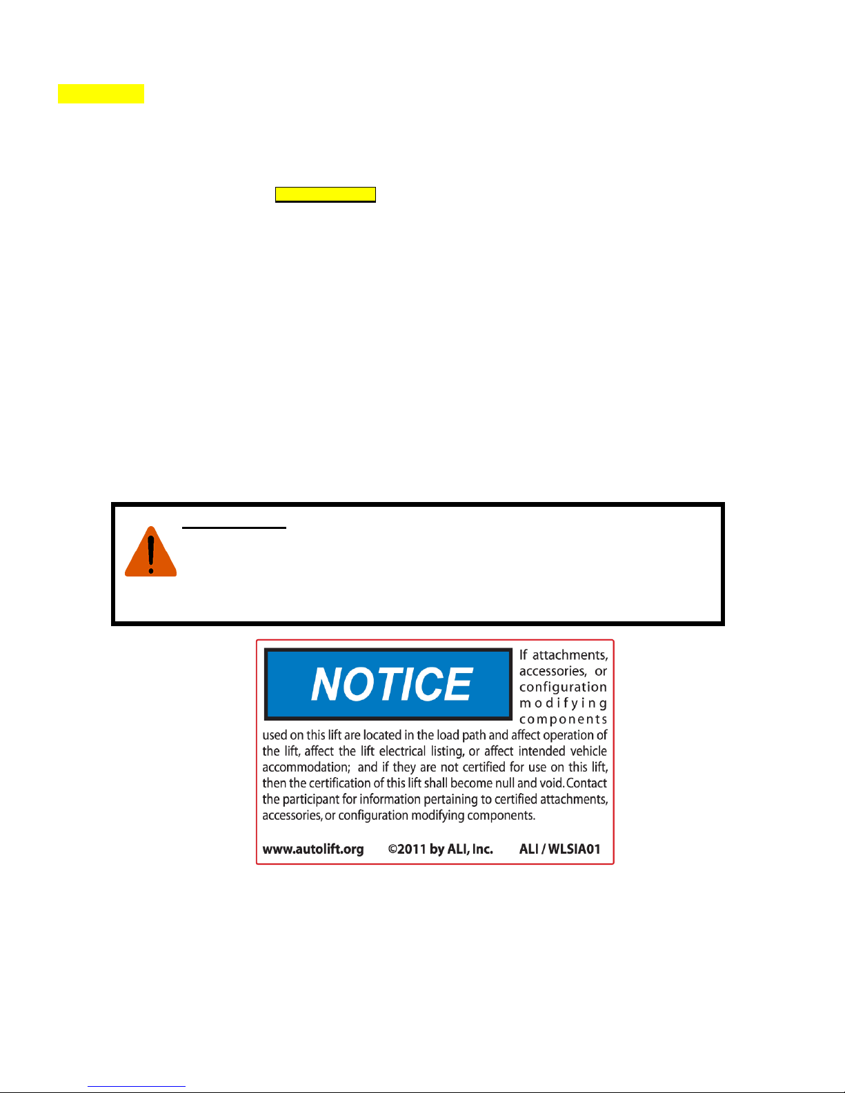
7. The Owner/Employer shall not modify the lift in any manner without the prior written consent of
the manufacturer.
IMPORTANT SAFETY INSTRUCTIONS
When using this lift, basic safety precautions should always be followed, including
the following:
1. Read all instructions in this manual and on the lift thoroughly before
installing, operating, servicing or maintaining the lift.
2. Care must be taken as burns can occur from touching hot parts.
3. Do not operate equipment with a damaged cord or if the equipment has been
dropped or damaged – until it has been examined by a qualified service
person.
4. Do not let a cord hang over the edge of the table, bench, or counter or come
Page 3

4
in contact with hot manifolds or moving fan blades.
5. If an extension cord is necessary, a cord with a current rating equal to or more
than that of the equipment should be used. Cords rated for less current than the
equipment may overheat. Care should be taken to arrange the cord so that it
will not be tripped over or pulled.
6. Always unplug equipment from electrical outlet when not in use. Never use
the cord to pull the plug from the outlet. Grasp plug and pull to disconnect.
7. Let equipment cool completely before putting away. Loop cord loosely around
equipment when storing.
8. To reduce the risk of fire, do not operate equipment in the vicinity of open
containers of flammable liquids (gasoline).
9. Adequate ventilation should be provided when working on operating
internal combustion engines.
10. Keep hair, loose clothing, fingers, and all parts of body away from moving parts.
11. To reduce the risk of electric shock, do not use on wet surfaces or expose to rain.
12. Use only as described in this manual. Use only manufacturer’s
recommended attachments.
13. ALWAYS WEAR SAFETY GLASSES. Everyday eyeglasses only have impact
resistant lenses; they are not safety glasses.
14. Inspect lift daily. Do not operate if it malfunctions or problems have been
encountered.
15. Never attempt to overload the lift. The manufacturer’s rated capacity is shown
on the identification label on the power side column. Do not override the
operating controls or the warranty will be void.
16. Only trained and authorized personnel should operate the lift. Do not allow
customers or bystanders to operate the lift or be in the lift area.
17. Position the lift support pads to contact the vehicle manufacturers
recommended lifting points. Raise the lift until the pads contact the vehicle.
Check pads for secure contact with the vehicle.
18. Caution! Never work under the lift unless the mechanical safety locks are
engaged.
19. Note that the removal or installation of some vehicle parts may cause a critical
load shift in the center of gravity and may cause the vehicle to become unstable.
Refer to the vehicle manufacturer’s service manual for recommended
procedures.
20. Always keep the lift area free of obstruction and debris. Grease and oil spills
should always be cleaned up immediately.
21. Never raise vehicle with passengers inside.
22. Before lowering check area for any obstructions.
23. Before removing the vehicle from the lift area, position the columns to prevent
damage to the lift and /or vehicle.
24. Check and adjust if need the correct air pressure in all tires before lifting. Do
not exceed tire load when raising vehicle.
25. DO NOT raise / lower only one side if a vehicle.
26. Lift only on same axle. Do not stagger between axles.
27. Do not drive over or pinch the electrical communication cables.
28. Do not remove hydraulic fittings while under pressure.
29. Check floor to ceiling height for clearance when vehicle is fully raised.
Page 4
3
WARNING!
Failure by purchaser to provide the recommended mounting surface could result in unsatisfactory lift
performance, property damage, or personal injury.
LOCATION
This lift has been evaluated for
indoor use only
with an operating ambient temp. range of 5 - 40°C (41-104°F)
For additional safety instructions regarding lifting, lift types, warning labels, preparing to lift,
vehicle spotting, vehicle lifting, maintaining load stability, emergency procedures, vehicle
lowering, lift limitations, lift maintenance, good shop practices, installation, operator training
and owner/employer responsibilities, please refer to “Lifting It Right” (ALI/SM) and “Safety
Tips” (ALI/ST) and vehicle lift points for service garage lifting SAE J2184.
For additional instruction on general requirements for lift operation, please refer to
“Automotive Lift-Safety Requirements for Operation, Inspection and Maintenance” (ANSI/ALI
ALOIM).
Installation shall be performed in accordance with ANSO/ALI ALIS, Safety Requirements for
Installation and Service of Automotive Lifts.
ATTENTION! This lift is intended for indoor installation only. It is prohibited to
install this product outdoors. Operating environment temperature range should be
41 – 104 °F (5 – 40 °C). Failure to adhere will result in decertification, loss of
warranty, and possible damage to the equipment.
Page 5

4
REFERENCE: AUTOMOTIVE LIFT INSTITUTE
SAVE THESE INSTRUCTIONS
Note: Some images in this manual are generic and may not resemble the lift you
have purchased.
Page 6

5
SPECIFICATIONS
Specifications
Certified Lift Models
Model
ML-4030BC
ML-6045BC
ML-4034BC
ML-6051BC
Lifting Capacity per Column
16,500 lbs. / 7,500 kl.
16,500 lbs. / 7,500 kl.
18,500 lbs. / 8,400 kl.
18,500 lbs. / 8,400 kl.
Column Configuration
Single/ Pair
Single/ Pair
Single/ Pair
Single/ Pair
Four
Four / Six
Four
Four / Six
Maximum Lift Capacity
66,000 lbs. / 30,650 kl.
99,000 lbs. / 44,900 kl.
74,000 lbs. / 33,560 kl.
111,000 lbs. / 50,350 kl.
Maximum Lifting Height
67" / 170 cm.
67" / 170 cm.
67" / 170 cm.
67" / 170 cm.
Lifting Time with Maximum
Load*
95 Seconds
95 Seconds
98 Seconds
98 Seconds
Lowering Time with Maximum
Load-
100 Seconds
100 Seconds
105 Seconds
105 Seconds
Carriage Type
Adjustable
Adjustable
Adjustable
Adjustable
Tire Diameter Sizes
19" - 44" / 43 cm-112
cm.
19" - 44" / 43 cm-112
cm.
19" - 44" / 43 cm-112
cm.
19" - 44" / 43 cm-112
cm.
Power Unit
24 Volt DC Electric Hydraulic
Power Supply
Dual 12 Volt Industrial Grade Deep Cycle Battery
with 120 Volt Battery Charging System per column
Shipping Weight per Column
1605 lbs. / 730 kl.
1606 lbs. / 730 kl.
1700 lbs. / 771 kl.
1701 lbs. / 771 kl.
Shipping Dimensions
49" Length x 47" Width x 89" Height / 125 cm. Length x 119 cm. Width x 226 cm Height
Warranty
Two Years Limited
*Lifting and lowering speeds may vary depending on the weight of the vehicle. Speeds shown are at maximum
weight load.
PACKING LIST
The complete lift is a set of four (4) mobile column lifting units and one (1) parts carton.
1. Each column is a self-contained unit.
2. The parts carton contains:
Four (4) communication cables.
Four (4) column top dust covers
10 sets of bolts and washers to secure top covers.
Two (2) spare hydraulic fittings.
Two (2) keys for column door interlock
Important document packet that includes, Maxima Installation, Operation and
Maintenance Manual, ALI Manual, “Lifting it Right”, Automotive Lift Safety Tips Placard,
ALI “Lifting Points Guide”, ANSI/ALI ALOIM:2008 Safety Requirements for Operation,
Inspection and Maintenance.
Warranty Statement and Warranty Registration Instructions.
INSTALLATION REQUIREMENTS AND TOOLS / SUPPLIES
Page 7

6
Foundation
Important: It is the user’s responsibility to provide a satisfactory installation area for the lift. Lifts
should only be installed on level concrete floors with a minimum thickness of four inches (4") or
102 mm. Concrete must have a minimum strength of 3500 psi and should be aged thirty (30)
days prior to installation. Please consult an architect, contractor or engineer if doubt exists as to
the strength and feasibility of the floor to enable proper lift installation and operation. Do not use
on asphalt. Do not use on a suspended floor without approval from a licensed structural
engineer.
A qualified person should be consulted to address seismic loads and other local or state
requirements.
It is the user’s responsibility to provide all wiring for electrical hook-up prior to installation and to
insure that the electrical installation conforms to local building codes. Where required, it is the
user’s responsibility to provide an electrical isolation switch located in close proximity to the lift
that will enable emergency stop capability and isolate electrical power from the lift for any
servicing requirements.
Tools / Supplies
1. Cutting device to remove packaging.
2. Metric wrenches.
3. 6 mm allen wrench
4. Clean funnel for adding hydraulic oil.
5. Clean new * AW-32 Hydraulic Oil
Hydraulic Oil needed per model
ML-4030BC 13 Gallons / 49.2 Liters
ML-6045BC 19.5 Gallons / 73.8 Liters
ML-4034BC 15 Gallons / 56.8 Liters
ML-6051BC 22.5 Gallons / 85.2 Liters
*Note: Use only new fresh clean AW-32 Hydraulic Oil. The use of
transmission fluids will void the lift warranty.
Installation Instructions
When the lift arrives on site:
Check for any freight damages. The shipment should be thoroughly inspected as soon
as it is received. The signed bill of lading is acknowledgement by the carrier of receipt in
good condition of shipment covered by our invoice. If any of the goods called for on your
bill of lading are shorted or damaged, do not accept them until the carrier makes a
notation on the freight bill of the missing or damaged goods. Do this for your own
protection. Check the contents of the accessory and hardware boxes to make sure no
parts are missing.
NOTE: IT IS DIFFICULT TO COLLECT FOR LOSS OR DAMAGE AFTER YOU HAVE
GIVEN THE CARRIER A CLEAR RECEIPT. THE LIFT MANUFACTURER IS NOT
RESPONSIBLE FOR ANY FREIGHT DAMAGE.
Page 8

7
Unpacking Procedure
Remove all plastic wrap and cardboard. Be careful not to cut into the lower hydraulic
hoses and fittings or to scratch the paint or damage the safety decals.
Use a 13 mm wrench remove the forklift brackets attached on the top of the carriage and /
or the column sides.
Carefully open the parts carton, avoid cutting the enclosed communication cables.
Remove all of the cables, column cover, spare parts and document packet.
Preparing Lift for Initial Startup
To transport the columns to a location in the repair facility for setup requires that the lifts be
moved. To easily move the columns, raise and lower the trolley handle in a pumping motion 35 times until the inner lower column edge is lifted from the floor. You can now maneuver the
lifts to any location by pulling the trolley handle to the desired location. Once you have moved
the lifts into position squeeze the release lever to lower the column to the floor. The lifts will
not operate unless the columns are lowered.
Installing the column covers: Inside the parts carton are four (4) column covers that should be
fitted and bolted to the open column tops using the provided bolts, washers and lock washers.
Adding hydraulic oil: To open the column main door, move the trolley handle to the extreme
right position to prevent the door from hitting the handle when opened. Use the 6 mm allen
wrench and remove the 3 door bolts on the left side of the column and open the main lift
cabinet. The hydraulic power unit tank will have a red plastic plug in the top opening and black
breather plug on the bottom outer edge of the tank. Remove both items and put the red plug
in the bottom hole. (The tank does not have a drain hole) Use a clean funnel and add new
hydraulic oil (AW-32) to the tank and fill to approx. 2” from the top of the tank fill hole. The
approx. amount of oil per column is shown below:
ML-4030BC 13 Quarts / 12.3 Liters
ML-6045BC 13 Quarts / 12.3 Liters
ML-4034BC 15 Quarts / 14.3 Liters
ML-6051BC 15 Quarts / 14.3 Liters
Install the black breather cap in the top of the tank. Close cabinet door and secure with the top
and bottom bolts. The center bolt secures the battery charger bay door and does not need to
be re-installed. (If the battery charger door tends to stay open,
then loosely re-install the bolt by hand to secure the door thereby making future battery
charging procedures faster)
Note: The hydraulic system was tested during manufacturing. Each hydraulic cylinder and the
power unit tank was filled and cycled to test for leaks and for performance. During this
process the hydraulic cylinders were bleed to remove any air. The hydraulic oil was removed
from the tank after testing. Because residual oil at the bottom of the tank and inside the
cylinder remain, additional hydraulic system bleeding is not necessary.
Battery charging: The LCD display panel will advise you if the batteries need to be charged.
To charge the batteries open the battery charger access door on the left side of the column by
Page 9

8
removing the bolt and then pull outward on the black knob and fully open the door. A battery
charger is built in to each column. Plug the battery charger electrical cord into a 110 volt
grounded electrical outlet. Charge each mobile column lifts using a separate electrical outlet.
Best performance will be obtained by charging all mobile column batteries at the same time.
Each battery charger front panel has a red and green indicator light. When the indicator light
is red means the battery is charging. When the indictor light is green means the battery is fully
charged.
When the lifts are new, charge the batteries for the first time approx. 12-15 hours or until the
battery charger indicator light turns green. Battery charging after 20-30 cycles will typically
take 6-8 hours. When the batteries are fully charged, disconnect the electrical cable and store
in the charger bay. Close the access door and loosely secure the door with the bolt.
Please note the safety information below:
An extension cord should not be used unless absolutely
necessary. Use of improper
extension
cords could result in a risk of fire or electric shock. If extension cords must be used, make
sure the following safety precautions are observed.
That the pins of plug of the extension cord are the same
number, size and shape of those of the
plug on the battery
charger.
That the extension cord is properly wired and in good
electrical condition.
That the wire in
the
extension cord is proper size as recommend below.
Minimum
recommended wire size for various length
extension cords used with each battery charger:
Length
of Cord
25'
50'
100'
Cord Gauge
16 Gauge
14 Gauge
12 Gauge
Do not operate the battery charger with a damaged cord or plug.
Do not operate the battery charger if it has received a sharp blow, been dropped or
otherwise damaged in any way.
Do not disassemble the charger. Incorrect reassembly may result in a risk of electric
shock or fire.
To reduce the risk of electric shock, unplug the charger from outlet before attempting any
maintenance or cleaning. Disconnecting the leads will not reduce this risk.
To reduce the risk of shock or spark, never touch the ring terminals together while the
charger is plugged into an outlet or extension cord.
External connections to the battery charger shall comply with all local, state, and federal
regulations.
CAUTION RI
SK OF EXPLOSIVE GASES
WORKING IN THE VICINITY OF A LEAD ACID BATTERY IS DANGEROUS. BATTERIES
CONTAIN SULFURIC ACID AND PRODUCE EXPLOSIVE GASES. A BATTERY EXPLOSION
COULD RESULT IN LOSS OF EYESIGHT OR SERIOUS BURNS. FOR THIS REASON, IT IS
OF UTMOST IMPORTANCE THAT YOU FOLLOW THE INSTRUCTIONS EACH TIME YOU
USE THE CHARGER TO REDUCE THE RISK OF BATTERY EXPLOSION, FOLLOW THESE
INSTRUCTIONS AND THOSE PUBLISHED BY THE BATTERY MANUFACTURER FOR ANY
EQUIPMENT YOU INTEND TO USE IN THE VICINITY OF THE BATTERY. REVIEW
CAUTIONARY MARKINGS ON THESE PRODUCTS AND ON ENGINE, MOTOR OR OTHER
EQUIPMENT REQUIRING BATTERY USAGE.
Page 10

9
System testing before actual use
(Do not do any testing using a vehicle)
Familiarize yourself with the electronic controls and warning lights by reviewing
the functions of each item listed below.
The Electronics:
The electronic control system of ML-4030BC and ML-4034BC includes one master and three
slave control panels. The electronic control system of the ML-6045BC and ML6051BC includes
one master and five slave control panels. Each column has one displacement sensor, one
electric hydraulic pump, one micro-switch, and one electromagnet.
The photos below illustrate the Master and Slave control panels
Master Control Panel
Emergency button
POWER light
Mode selection knob
FAULT light
“LOCK” button
“UP” button
“DOWN” button
LCD
Connector
Connector
Page 11

10
Slave Control Panel
Control switches:
Power switch: (located on the right side of each column) when this switch is at “OFF”, the
lift is powered off and no operation is available; when this switch is at “ON”, the lift is
powered on and prepared for operation.
Power light: when the power switch is at “ON”, it illuminates.
Fault light: it illuminates when the carriages have overrun the limit synchronous value of
each column or the communication cables becomes loose, at this point all the other
switches do not work.
Mode selection knob: turn the knob to “SINGLE”, columns can be operated to go up and
down individually: Turn the knob to “PAIR” or “ALL”, two columns/four columns/six
columns can be operated to go up and down together.
Emergency button: when you press this switch, no operation is available immediately.
There is one emergency button on each control box. It must be released before lift
operation then turn on the power switch.
“UP” button: Press and hold this button, the carriages will rise.
“DOWN” button: Press and hold this button, the carriages go down to the required height
after system unlocks the safety locks automatically.
“LOCK” button: Press and hold this button, the carriage will slowly lower and lock onto
first lowest column.
Note:
Before turning Mode Selection knob, power off the lift and wait for 20 seconds.
“PAIR” mode can be used when four/six columns are communicating…A and B columns
become a pair, same with C and D columns. Use caution when using this function to keep
vehicle level. “ALL” mode is used when there are four/six columns connected together.
“SINGLE” mode can be used to operate one column individually;
LCD
POWER light
Emergency button
Connector
Connector
“LOCK” button
“UP” button
FAULT light
“DOWN” button
Page 12

11
In case of an emergency, use the key to access the control panel and move the switch to right
side as illustrated below so that the equipment can be operated without the communication
cables connected. The switch is located at the extreme lower left side of the circuit board next to
the fuse holder.
Make sure that you have connected all communication cables according to Fig. 1 and Fig. 2
before operation.
Four Column Configuration
Fig. 1
Six Column Configuration
Fig. 2
Move the switch to the right
Page 13

12
Operation test:
Power on: Connect all 4/6 columns with communication cables as shown above, turn the Mode
Selection knob to SINGLE, and power on main column and all slave columns. LCD screen will
show work interface after successful connection.
Rise: Unloaded, press and hold the “UP” button on the master control box, check if the carriage
rises normally. Repeat to try the other columns in same way
Press and hold the “UP” button and allow the carriage to rise to its highest position. Check for any
hydraulic leaks.
Emergency stop: Press the red emergency button to stop the lift. Turn red button to the right to
release it after testing to see if the columns have stopped.
Lower: Press and hold the “DOWN” button, the carriages go down to the required height after the
safety locks have disengaged automatically.
“PAIR” or “ALL” columns test:
Power on: Connect all 4/6 columns with communication cable according to Fig.1 or Fig. 2, turn
the Mode Selection knob to PAIR or ALL mode, and power on main column and all slave
columns. LCD screen will show work interface after successful connection.
Rise: Unloaded, press and hold the “UP” button at the master control box, check if all the
corresponding carriages can rise normally.
Emergency stop: Press the red emergency button to stop the lift. Turn red button to the right to
release it after testing to see if the columns have stopped.
Lock: Press and hold this button, the carriage will slightly go down and will lock into the closest
safety lock. Use the lock button every time you operate the lifts.
Lower: To lower you must raise lifts a few inches for the safety locks to disengage then press and
hold the “DOWN” button, the carriages go down to the required height after the safety lock
disengage.
After you have read and understand all of the information in this manual
and finished the operations testing you are ready to proceed to lifting
vehicles. All technicians that will be using this equipment MUST
read and understand all of the safety and operation items in this
manual.
Page 14

13
Lifting Vehicles:
1. Check and correct the tire pressure in each tire.
2. Position each mobile column adjacent to each tire on the vehicle. If the vehicle has dual
rear axles position the mobile columns to use on the drive axle. Note: If an older vehicle
has air bag suspension on the non-drive axles and mobile column are not used, extra
support for the axles may be needed to prevent air bag damage. Consult with the vehicle
manufacturer to determine if the air bag suspension has mechanical stops.
3. Adjust the lifting arms so they are at the narrowest position that will allow the arms to
position under the tires. To adjust the arms lift and slide the arms inward as shown below.
4. After adjusting the lifting arms, raise the lift slightly using the jacking trolley and position
the lifts arms as far inward as possible. Notice the position of the column top in relationship
to external mirrors or vehicle body. Always maintain approx. 6 inches of clearance
between the column top and the vehicle. Lower the lift using the trolley hydraulic release
handle. Note: The lift will not operate when the columns until the column trolley is fully
lowered.
5. Connect all communication cables as show in Fig. 1 or Fig. 2.
6. Turn the mode selection knob to “ALL” and turn the power control switch on the side of the
lift to “ON” on the master control panel and all slave control panels.
7. Depress the “UP” button and all columns will rise approx. 6 inches and the lift will stop and
make an audible beeping sound. Release the “UP” button and use this time to inspect all
of the columns to insure that the lifting arms are positioned properly.
8. Depress the “UP” button again and raise the vehicle to the desired height. Note: During the
raising process you may notice one or more columns stop lifting momentary, this occurs
when the lift control system is synchronizing each column to maintain level lifting. This is
normal.
9. After reaching to the desired height, press the “LOCK” button. All lift columns will lower to
the first available safety lock position. When the lifts have settled onto the safety locks
release the “Lock” button. The lift is now safe and secured and ready for vehicle service.
10. To lower the lifts, check that all tools and equipment and has been removed from under
the vehicle. Press and hold the “UP” button for a few seconds to allow the lifts to raise 3-4
inches above the safety locks. Release the “UP” button and then press the “DOWN”
button. The lifts will lower slowly to the floor. At approx. 6 inches from the floor the lifts will
make an audible beeping sound. This is a safety reminder to double check that nothing in
under the tires or lifting arms. Double check the communication cables are also clear of
the lifting arms.
Page 15

14
11. To move the vehicle, turn off the power at all lift columns and disconnect the
communication cables. Move the mobile columns safely away from the vehicle before
attempting to move the vehicle. Use caution to not drive over the communication cables.
Maintenance Instructions
Caution: If you are not familiar with vehicle lift maintenance and service procedures, do not
attempt repairs and contact the factory for assistance. Use only experienced lift service
technicians to perform lift maintenance.
Daily: Check hydraulic system for leaks.
Check the safety lock mechanism.
Check communication cables for damage
Inspect lifting forks and insure they are in proper location and engaged in the locks.
Monthly: Test the emergency stop button on all columns. Columns should stop immediately.
Check the battery charging cables and cable ends.
Inspect communication cables and cable ends for wear or damage.
Check oil levels in hydraulic pump tank. If oil is needed follow directions on page 7.
Annually: Have a ALI Certified Lift inspector check all of your vehicle lifts and the safety
systems for wear or damage.
_______________________________________________________________________
System Diagnostic Codes
The mobile column lifts have self-diagnostic systems that may display a fault code on the LCD
screen. Most fault codes indicate some sort of operator error and are designed so the user can
correct the most common operation mistakes without employing a service technician. Listed
below are the most common fault codes.
Error Code 1-X: X means different column, for example, 2 means column B, 3 means column
C, 4 means column D. Check the indicated column. Check connections between columns,
confirm all power switches have been powered on, and ensure no emergency button has been
pressed down.
Error Code 2: Mode shift error. Do not change working mode during operation. Select the
correct operation mode and restart the equipment.
Error Code 4-X: Check communication between columns.
Page 16

15
Error Code 5-X: Check for overheated power unit. The control panel has power unit cycle times
posted. If these times are exceeded the power may overheat. If this occurs allow the power unit
to cool off to the recommended duty cycle time
Error Code 6: “UP” and “DOWN” buttons have been pressed at the same time.
Error Code 7: The equipment has non-synchronization situation. If this happens when powering
on, please check if there is height difference which is more than 2 inches among columns, and if
yes, change working mode to “SINGLE”, and adjust the 4 columns to be same; if this happens
during going up, please check the 2-way-3-position valve on the highest column; if this happens
during descending, please check if there is leakage with two 2-way-2-position valves.
Error Code 8-X: Electromagnet has not been actuated. Please check micro switch. Change to
“SINGLE” mode, press “DOWN” to see if electromagnet has been actuated. If no, please check
the connection between electromagnet and connecting lines.
Error Code 9-X: Safety lock failed to lock the carriage. Check whether safety lock can exit
electromagnet, if no, please check safety lock; if yes, please check micro switch. When safety
lock leaves the electromagnet, its compression bar should not contact micro switch.
Error Code 12-X: Change-over switch is in wrong position. Open control panel with access key
and move position switch as shown on page 11 of this manual.
_____________________________________________________________________________
Service
Caution: If you are not familiar with vehicle lift maintenance and service procedures, do not
attempt repairs and contact the factory for assistance. Use only experienced lift service
technicians to perform lift maintenance.
Before and vehicle lift is serviced, follow the proper procedure for lock / out tag / out
below.
Rules for Using Lockout Procedure
Use the Lockout Procedure whenever the lift is being repaired or serviced, waiting for repair when
current operation could cause possible injury to personnel, or for any other situation when
unintentional operation could injure personnel. No attempt shall be made to operate the lift when the
energy isolating device is locked out.
Purpose
This procedure establishes the minimum requirements for the lockout of energy that could cause
injury to personnel by the operation of lifts in need of repair or being serviced. All employees shall
comply with this procedure.
Page 17

16
Responsibility
The responsibility for assuring that this procedure is followed is binding upon all employees and
service personnel from outside service companies (Installers, contactors, service repairmen). All
employees shall be instructed in the safety significance of the lockout procedure by the facility
owner/manager. Each new or transferred employee along with visiting outside service personnel
shall be instructed by the owner/manager (or assigned designee) in the purpose and use of the
lockout procedure
Preparation
Employees authorized to perform lockout shall ensure that the appropriate energy isolating device
(circuit breaker,
fuse, disconnect, etc.) is identified for the lift being locked out Other such devices for
other equipment may be located in close proximity of the appropriate energy isolating device. If the
identity of the device is in question, see the shop supervisor for resolution. Assure that proper
authorization is received prior to performing the lockout procedure.
Sequence of Lockout Procedure
Notify all affected employees that a lockout is being performed and the reason for it.
Unload the subject lift. Shut it down and assure the disconnect switch is "OFF" if one is provided on
the lift.
The authorized lockout person operates the main energy isolation device removing power to the
subject lift.
If this is a lockable device, the authorized lockout person places the assigned padlock on the device
to prevent its unintentional reactivation. An appropriate tag is applied stating the person's name, at
least 3"x 6" in size, an easily noticeably color, and states do not operate device or remove tag.
If this device is a non-lockable circuit breaker or fuse, replace with a "dummy" device and tag it
appropriately as mentioned above.
Attempt to operate lift to assure the lockout is working. Be sure to return any switches to the "OFF"
position.
The equipment is now locked out and ready for the required maintenance or service.
Restoring Equipment to Service
Assure the work on the lift is complete and the area is clear of tools, vehicles, and personnel.
At this point, the authorized person can remove the lock (or dummy circuit breaker or fuse) & tag and
activate the energy isolating device so that the lift may again be placed into operation.
___________________________________________________________________________
Page 18

17
Lift Parts and Drawings
ML-4030BC/ML-6045BC Mechanical Parts List
ITEM
DESCRIPTION
CODING
ITEM
DESCRIPTION
CODING
1
Column
2030048-0011
42
Big Cover
2030014-0040
2
Reinforce Bracket
2030047-1000
43
Battery Fixing Frame
2030014-0041
3
Bumper
1150009-0025
44
Up Battery Seat
2030014-0043
4
Torsion spring
1040018-0003
45
Battery Fixing Strip
2020010-0194
5
Safety Hook
2040009-1000
46
Fixing Bracket
2030051-0001
6
Hook shaft
2040002-1000
47
Bolt With Slot
2020002-0153
7
Long Bar
2040008-1005
48
Under Battery Seat
2030014-0048
8
Pin C
2040002-0146
49
Power Switch
1130004-0081
9
Pin A
2040002-1001
50
Fuse Fixing Strip
2030056-0002
10
Pin B
2040002-1002
51
Charger Door
2030014-0044
11
Short Bar
2040008-0067
52
Battery
1130014-0008
12
Clip
2040010-1007
53
Flat Washer 30
2020005-1006
13
Electromagnet Bracket
2030056-0001
54
Sheave
2020006-1000
14
Sensor Bracket
2030057-1000
55
Sensor
2060004-1009
15
Micro-switch Bracket
2020010-0153
56
Micro-switch
1130004-0082
16
Carriage
2030063-0004
57
Electromagnet
1130010-0006
17
Rubber Hose
1140005-0104
58
Fuse Box
1130003-0026
18
Short Hose
2040011-1001
59
Fuse 0298150
1130003-0023
19
Steel Ball Fixing Cover
2040005-0041
60
Charger
1130014-0062
20
Cylinder
1140001-0010
61
Charger Wire
1100001-0145
21
Active Fitting ( For Hydraulic)
1140004-0203
62
Switch Sol Act
800201389
22
Hydraulic Throttle Screw
1140008-0103
63
Mandril
2030007-0039
23
Side Sliding Block
2020014-1001
64
Under Micro-switch Bracket
2020010-0323
24
Cylinder Adjusting Washer
2040005-1000
65
Hydraulic Power Unit
1140002-0030
800601677
25
Shim
2040007-0012
66
Motor, Dc,24v 2Term
800201264
26
Shaft Sheath
2040005-1034
67
Base Valve Block
800500967
Page 19

18
27
Swing Block
2040008-1008
68
Plug
800201457
28
Slider Block
2020008-1016
69
Resv,Plastic,9*10*18
500206414227
29
Holding Fork Arm
2030067-0001
70
Pressure Relief Valve
50020852019603
30
Hydraulic Dolly
2050034-1002
71
Active Fitting NPT3/8
1140004-0254
31
Left Crank
2040063-0002
72
Right-angle Fitting NPT3/8
1140004-0035
32
Right Crank
2040063-0003
73
Little Poppet Assy
500216101723100
33
Support shaft
2040002-0206
74
Big Poppet Assy
500216101723200
34
Outer Shaft 20
2040002-0214
75
Cartridge ,2W/2P Valve
50020160719304
35
Inner Shaft
2040002-0217
76
Cartridge ,2W/2P Valve
With Manual Override Knob
50020161877104
36
Long Shaft
2040002-0215
77
Coil, 24VDC
50020191115204
37
Outer Shaft
2040002-1037
78
38
Dustproof Cover
2030014-1022
79
39
Long linkage
2040063-0001
80
40
Truckle
2040006-0056
81
41
Pendulum block
2040074-0002
82
Page 20

19
Page 21

20
ML-4030BC/ML-6045BC /ML-4034BC/ML-6051BC Electric Parts List
ITEM
DESCRIPTION
CODING
ITEM
DESCRIPTION
CODING
1
Master Control Box Door
2040029-0108
13
Fault Light
1130004-0077
2
Slave Control Box Door
2040029-0109
14
E-Stop
1130004-0075
3
Seal Strip
1150009-0021
15
Control Board
2060002-0064
4
Main Board Fixing Pedestal
2040084-0001
16
Wiring duct-slot
1130012-0084
5
Contactor Fixing Pedestal
2040008-0068
17
Cable
1100001-0137
6
Control Box Body
2030014-0083
18
Heavy Duty Plug
1130012-0096
7
LCD
1090028-0206
19
Female Connector
1130012-0094
8
Lock
1050008-0023
20
Male Connector
1130012-0093
9
Push Button
1130004-0074
21
Heavy Duty Socket
1130012-0095
10
Select Switch
1130004-0076
22
Cable Gland
1050002-0003
11
Power light
1130004-0078
23
Brass Cable Gland
1050002-0014
12
Pin
2040002-1005
Page 22

21
Page 23

22
ML-4034BC/ML-6051BC Mechanical Parts List
ITEM
DESCRIPTION
CODING
ITEM
DESCRIPTION
CODING
1
Column
2030048-0012
42
Big Cover
2030014-0040
2
Reinforce Bracket
2030047-1000
43
Battery Fixing Frame
2030014-0041
3
Bumper
1150009-0025
44
Up Battery Seat
2030014-0043
4
Torsion spring
1040018-0003
45
Battery Fixing Strip
2020010-0194
5
Safety Hook
2040009-1000
46
Fixing Bracket
2030051-0001
6
Hook shaft
2040002-1000
47
Bolt With Slot
2020002-0153
7
Long Bar
2040008-1005
48
Under Battery Seat
2030014-0048
8
Pin C
2040002-0146
49
Power Switch
1130004-0081
9
Pin A
2040002-1001
50
Fuse Fixing Strip
2030056-0002
10
Pin B
2040002-1002
51
Charger Door
2030014-0044
11
Short Bar
2040008-0067
52
Battery
1130014-0008
12
Clip
2040010-1007
53
Flat Washer 30
2020005-1006
13
Electromagnet Bracket
2030056-0001
54
Sheave
2020006-1000
14
Sensor Bracket
2030057-1000
55
Sensor
2060004-1009
15
Micro-switch Bracket
2020010-0153
56
Micro-switch
1130004-0082
16
Carriage
2030063-0010
57
Electromagnet
1130010-0006
17
Rubber Hose
1140005-0104
58
Fuse Box
1130003-0026
18
Short Hose
2040011-1001
59
Fuse 0298150
1130003-0023
19
Steel Ball Fixing Cover
2040005-0041
60
Charger
1130014-0062
20
Cylinder
1140001-0027
61
Charger Wire
1100001-0145
21
Active Fitting ( For Hydraulic)
1140004-0203
62
Switch Sol ACT
800201389
22
Hydraulic Throttle Screw
1140008-0103
63
Mandril
2030007-0039
23
Side Sliding Block
2020014-1001
64
Under Micro-switch Bracket
2020010-0323
24
Nut
2040004-1053
65
Hydraulic Power Unit
1140002-0030
800601677
25
Shim
2040007-0012
66
Motor, Dc,24v 2Term
800201264
Page 24

23
26
Shaft Sheath
2040005-1034
67
Base Valve Block
800500967
27
Swing Block
2040008-1008
68
Plug
800201457
28
Slider Block
2020008-1106
69
Resv,Plastic,9*10*18
500206414227
29
Holding Fork Arm
2030067-0001
70
Pressure Relief Valve
50020852019603
30
Hydraulic Dolly
2050034-1002
71
Active Fitting NPT3/8
1140004-0254
31
Left Crank
2040063-0002
72
Right-angle Fitting NPT3/8
1140004-0035
32
Right Crank
2040063-0003
73
Little Poppet Assy
500216101723100
33
Support shaft
2040002-0206
74
Big Poppet Assy
500216101723200
34
Outer Shaft 20
2040002-0214
75
Cartridge ,2W/2P Valve
50020160719304
35
Inner Shaft
2040002-0217
76
Cartridge ,2W/2P Valve
With Manual Override Knob
50020161877104
36
Long Shaft
2040002-0215
77
Coil, 24VDC
50020191115204
37
Outer Shaft
2040002-1037
78
38
Dustproof Cover
2030014-1022
79
39
Long linkage
2040063-0001
80
40
Truckle
2040006-0056
81
41
Pendulum block
2040074-0002
82
Page 25

24
Page 26

25
ML-4030BC/ML-6045BC /ML-4034BC/ML-6051BC Electric Parts List
ITEM
DESCRIPTION
CODING
ITEM
DESCRIPTION
CODING
1
Master Control Box Door
2040029-0108
13
Fault Light
1130004-0077
2
Slave Control Box Door
2040029-0109
14
E-Stop
1130004-0075
3
Seal Strip
1150009-0021
15
Control Board
2060002-0064
4
Main Board Fixing Pedestal
2040084-0001
16
Wiring duct-slot
1130012-0084
5
Contactor Fixing Pedestal
2040008-0068
17
Cable
1100001-0137
6
Control Box Body
2030014-0083
18
Heavy Duty Plug
1130012-0096
7
LCD
1090028-0206
19
Female Connector
1130012-0094
8
Lock
1050008-0023
20
Male Connector
1130012-0093
9
Push Button
1130004-0074
21
Heavy Duty Socket
1130012-0095
10
Select Switch
1130004-0076
22
Cable Gland
1050002-0003
11
Power light
1130004-0078
23
Brass Cable Gland
1050002-0014
12
Pin
2040002-1005
Page 27

26
Maxima
A Division of MIT Automobile Inc.
1151 West 5
th
Street
Azusa, California 91702
626-774-5700
 Loading...