

Page 1
MAXIM
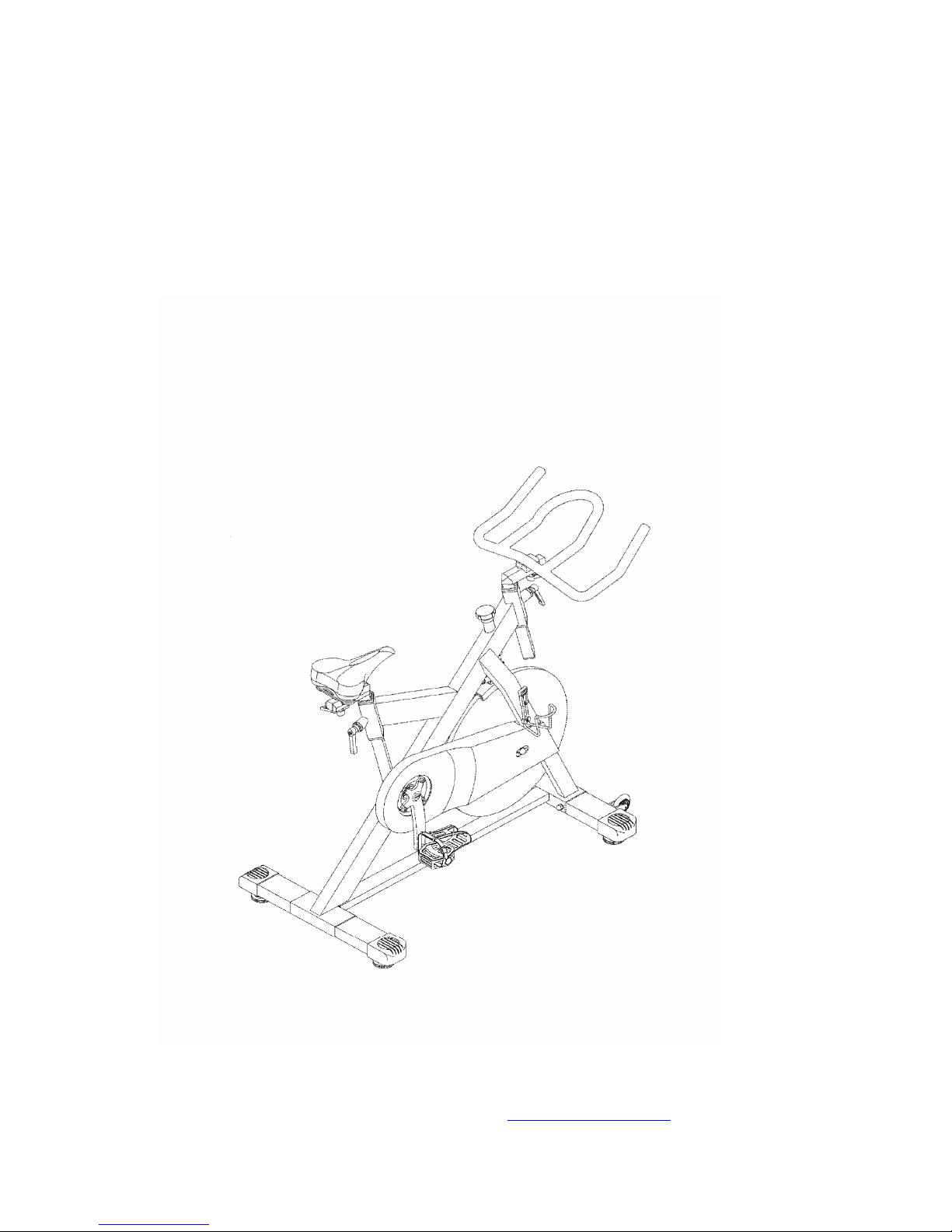
XTR 05 HORNET SPIN CYCLE
Operation Manual
Maxim Strength Fitness Equipment Pty Ltd
5 Valetta Road,
Kidman Park, 5025. South Australia
Telephone +61 884 433 001
Fax +61 884 433 668
Web www.maximfitness.net
Page 2

- 2 -
Page 3

- 3 -
CONTENTS
1. Contents Page 3
2. Preface 4
3. Instructions for use 5
4. Operational Overview 8
5. Service and Maintenance 10
6. Preventative Maintenance Schedule 13
7. XTR 05 Parts & Descriptions 14
8. XTR 05 Mk II Parts & Descriptions 16
Page 4

- 4 -
PREFACE
Before using this product it is essential that you read this ENTIRE operation manual
and
ALL installation instructions if applicable.
This will help in setting up the equipment quickly and in instructing others on how to
use it correctly and safely.
Statement of Purpose: This bike is an exercise machine that enables users to exercise
through pedaling.
Maxim Fitness strongly recommends seeing a physician for a complete medical
examination prior to undertaking an exercise program.
- Particularly if the user has a family history of high blood pressure or heart
disease
- Over the age of 45, or smokes
- High cholesterol, obese or has not exercised regularly in the past year.
If at any time while exercising, the user experiences faintness, dizziness, pain or
shortness of breath, he or she must stop immediately.
In the body of the text following many items are referred to by name and number i.e.
“Saddle (#17)” – The bracketed numbers are part number references to ensure correct
identification and are detailed in the drawings and indices at the end of this manual.
(Pages 14 -16)
Page 5

- 5 -
INSTRUCTIONS FOR USE
1. The HORNET Model XTR05 is specifically designed for use in ‘Spin’ Cycle
classes, fitness studios and health clubs. The bike uses a fixed wheel drive
flywheel and should only be used with professional supervision or instruction.
2.
Assembly: It is important that the bike is correctly assembled, and we
recommend that the installation and assembly be undertaken by suitably
qualified personnel. Detailed Assembly instructions are supplied separately
with an unassembled bike. If your bike was supplied preassembled follow the
service and maintenance instructions later in this manual. If you have
assembled the bike yourself ensure that all assembled procedures are correct
and recheck that all assembled parts are fully tightened. Recheck if necessary.
3.
Location: The bike should be placed in the desired location and then checked
that it is both level and stable. Each ground tube has adjustable leveling feet
located on the underside of each corner. Ensure that each of the leveling feet
are in a fully inserted position (Fully rotated CW when viewed from bottom)
Rotate feet CCW until the bike is both level and stable.
4.
Handlebar And Seat Stem Adjustment
It is important that the handlebar and seat height adjustments are correctly set
for your particular body dimensions – if you are undertaking any of the
various classes using spin cycles then your instructor will advise you as to the
correct adjustment procedures relative to the program you are undertaking.
Incorrectly adjusted bikes may produce can produce excessive strain, soreness
and / or irritation of muscles and joints.
The instructions that follow are to assist with bike set up
should you not have an instructor to advise you as to correct
and proper procedures.
Page 6

- 6 -
5. SADDLE (SEAT) ADJUSTMENT:
i) Grasp the saddle (#17) with which ever hand is most comfortable
and release the locking lever (#12) with the other hand.
Do not
allow the saddle assembly to drop
. Adjust the saddle height so
that when raised to a position underneath your armpit it allows the
tips of your extended fingers to align with the axle (#61) centre line.
Tighten the locking lever whilst the saddle is held in this position.
Sit on the bike saddle and recheck the position so that when the
foot is sitting on a pedal in the lowest position (6 o’clock) the knee
joint retains a slight bend. It should be possible to pedal without
fully straightening the legs (Locking the knees) or shifting in the
seat. Rolling on the saddle apart from indicating an incorrect
seating position damages and shortens the life of a saddle. Check
and make any further adjustment if necessary.
ii) When the saddle height is set, adjust the user settable fore / aft
position so that when seated and the feet are correctly positioned
on the pedals (#7R & #7 L) and, whilst the pedals are held in a
horizontal position (3 & 9 o’clock) the knee joint is in a vertical
position over the pedal.
6.
HANDLEBAR ADJUSTMENT:
i) Hold the handlebar (#14) with which ever hand is most
comfortable and release the lock lever (#18).
Do not allow the
handle to drop
. Raise or lower the stem so that the handle bar is in
line with or slightly above the saddle position. Retighten the lock
lever.
ii) Release the lock lever (#12) and adjust the handle bar fore/aft so
that when your elbow is place against the front of the seat (#17)
and the fingers are extended the fingers just reach the handle bar
(#11).
Page 7

- 7 -
This position should provide a comfortable posture when leaning
forward and resting on the forearm support as well as in an almost
upright position you are able to grip the bike handle cross bars.
Make any minor adjustments that may be necessary and retighten
the lock lever.
Check all lock levers and ensure that all are firmly tightened and
that there is no lateral or vertical movement of either the handle
bars or seat.
All lock levers have a variable start position. If rotation of a lock
handle is no longer possible due to the presence of another
component lift the lever and rotate it away from the component.
Release the lever in its new position and allow the lever to relocate.
Further rotation and tightening will be possible. Lever repositioning can also be used to enable the releasing of a lever lock
if the handle position is difficult to access.
Once a bike is set up properly keep a record of the setting positions
so they can be speedily reproduced in the future. All adjustable
moving parts are engraved with positional engravings to assist set
up.
7.
PEDAL STRAPS:
Pedal straps must be adjusted correctly. Place the foot on the pedal
so that the ball of the foot is centered over the pedal. Tighten the
strap so that the foot is secured in the pedal.
Safety lines are engraved on the seat post and the handlebar
stem. On no account should either the seat post or handle bar
stem be raised above these lines.
Page 8

- 8 -
OPERATIONAL OVERVIEW
The HORNET XTR 05 has a durable HD poly ’V’ belt drive system that will
provide years of trouble free use and is extremely smooth and quiet in
operation.. The braking system consists of a unique self aligning peripheral
brake complete with side pads that is designed to stand the rigors of
commercial use but still provide a smooth quiet and ultra reliable brake. The
linkage system provides exceptional peripheral contact to ensure a linear
braking effect relative to the load knob adjustment. There is negligible brake
fade regardless of duration of operation and if maintained correctly will
provide an extremely long service life. Refer to the maintenance procedures
following.
If you are using the bike in a class environment always follow the instructor’s
advice. If you are riding this style of bike for the first time apply a light brake
load and commence pedaling. Regulate the braking load as required by
rotating the braking control knob (#27). Clockwise rotation will increase load
as counterclockwise rotation will decrease load. Never remove all brake
loading whilst riding unless you are a competent and experienced user.
If a foot or feet become disengaged from the pedals whilst riding
DO NOT
attempt to place the feet back into the rotating pedals. Keep the feet well clear
of the pedals and apply the brake by pushing down on top of the brake knob.
The brake will stop the flywheel very quickly, depending on the effort applied
to the brake knob. Once stationary replace the feet in the pedals, check and
retighten pedal straps if necessary and recommence your exercise.
Page 9

- 9 -
Overview – cont.
If you are an experienced rider and both push and pull the pedal cranks whilst
riding you may prefer to fit ‘SPD’ clip-less pedals (Or similar). These provide
greater foot security and are available as an optional extra. Clip-less pedals
position the foot in the correct riding position and transfer the power from
your legs to the pedal without trying to bend your foot over the top of the
pedal. This is a much more efficient way of power transfer and will help
reduce both fatigue and pain from incorrect technique. Riding foot-ware is not
provided and must be sourced from other suppliers, i.e. a local specialist
bicycle shop will be happy to provide a service.
Properly maintained the Hornet XTR 05 will provide years of trouble free
operation.
ENJOY!!
Page 10

- 10 -
Service and Maintenance
Preventative maintenance tips
The safety of the equipment can be maintained only if equipment is examined
regularly for damage or wear. Keep equipment out of service where defective parts
are identified until these parts are repaired or replaced. Continued use of a defective
part will invariably cause more damage than would otherwise be the case.
The following tips will help keep the bike in peak operating condition -
1. If possible locate the bike in a cool dry place, avoiding any positions that are
in direct sunlight.
2. Ensure the pedal straps are fastened whilst the bike is being used.
3. Keep the bike clean, dry and free of sweat.
4. Use a 100% cotton cloth, moistened with water and a mild detergent solution.
Immerse the cloth in a mild water detergent solution, wring out the cloth to
remove excessive solution and completely wipe the handle bars, frame and
covers. Pay attention to the areas where a user will drip sweat particularly,
internal corners and joints that trap or allow sweat to pool.
5. Avoid using paper towels which are abrasive, and do not use ammonia or acid
based cleaners.
6. Clean on a regular basis. When the used in a class environment the bike
should be wiped down after every class and is best done by each user as part
of a warm down procedure. A good instructor will incorporate this as part of
any warm down and stretch procedures at the end of a class.
Periodically the frame and flywheel should be sprayed with a corrosion
preventative product. (Such as CRC 5.56® or WD40®) These products are
available in both aerosol or trigger action spray units. Lightly spray and then
wipe of an excess fluid. Do not spray on handle bars, saddle or pedals. The
product will leave a thin protective barrier that will help prevent sweat
corrosion. This application should always be completed after the frame etc has
been cleaned as described in (#4) above.
Page 11

- 11 -
7. If clip-less pedals are used it is best that bikes be dedicated for this use. The
pedals are permanently fitted to the cranks. Where clients change and fit their
own pedals the pedal security must be checked. Loose pedals will very quickly
destroy a bike crank. Generally a client will ensure that their pedals are tight
when fitted – however the same diligence is not always applied when they
refit/return the old pedal to the crank.
8. Crank removal requires a special tool and should only be removed by qualified
personal. Crank removal, crank locknut and pedal tools are available. These
are professional tools specifically designed for these applications and must be
ordered as spare parts.
There are tools specifically designed to assist with the removal and tightening of
pedals and crank arms. These tools are available but must be ordered separately.
These items can be purchased from your supplier, a reputable bike shop or from
Maxim Strength Fitness Equipment.
After the first week of use, the pedal crank arms will need to be
checked and tightened. Remove the plastic caps (#64) and using a
14mm socket re-tension both the LH and RH locknuts (#63).
Both threads are RH threaded.
Pedal shafts require a 15mm spanner to tighten – Remember
that a LH pedal is LH threaded (CCW rotation to tighten) and a
RH pedal is RH threaded (CW rotation to tighten)
Page 12

- 12 -
The following detail relates to the simple service procedures referred to in the service
schedule opposite.
1. Lubricate the two lock lever threads (#12) by completely unscrewing
the lock lever. Smear some grease on the tread and return to its original
position.
2. To lubricate the two lock lever threads (#18) firstly release the lock
levers and lower the stems fully. (Do Not Drop) Using a suitable
spanner (28mm or 1
⅛”) or shifter loosen the nut (#19) and remove the
lock lever assembly completely. Rotate the lever so that a maximum of
thread is exposed on the inner side and smear grease on the thread.
Rotate the lever counter clockwise to expose the maximum of thread
on the outside and smear the exposed thread similarly. Return the
assembly to its original position and retighten with a spanner or shifter.
Lift the seat or handle bar and re-clamp with the lock lever.
3. Grasp the saddle and check if there is any looseness, either a tendency
to tilt or slide. If any movement is detected or if any looseness or
movement in the seat is reported the matter must be attended to as
quickly as is possible. Movement in these areas will damage the seat
mounting mechanism. There are two points to monitor –
a) Socket head screws (4mm key) either side of the saddle clamp
(#26) must be tightened so that the saddle rails are held firmly.
The preferred position is centrally on the two seat rails. This
adjustment controls a fixed fore / aft movement of the saddle.
b) The socket head screw (6mm key) (#25) controls rotational or
the tilting movement of the seat. If a seat has rotated (tilted) –
Firstly loosen the clamp screw (#25) then correct the seat
attitude - preferred position is horizontal. When realigned
correctly, firmly retighten the clamp screw (#25)
Page 13

- 13 -
Preventative Maintenance Schedule
When used commercially Maxim Strength Fitness Equipment
strongly recommends that you instigate a regular service and
maintenance program. Warranties are always contingent on the
completion of proper and regular service and maintenance. If a
program has not been arranged already, Maxim or your supplier will
be glad to discuss the details of the service and maintenance facilities
that are available to you facility.
Contact the applicable service department.
Detail Daily Weekly Monthly
Wipe Clean I
Wash & Clean I
Spray with Anti-corrosion product I
Check All Slides and that lock levers
function correctly
I
Grease Lock Lever threads I
Security of saddle, frame screws, fixtures,
pedals and pedal cranks.
I
Pedal And Strap Security I
Check brake operation and adjustment I
If pedals are being substituted in daily use, the security of the
returned pedal must be checked daily. Do not rely on the client to
replace the old pedal correctly.
Page 14

- 14 -
XTR05 HORNET PARTS LIST
To suit the earlier round tube stem version
(All descriptions on opposite page)
Page 15

- 15 -
XTR 05 HORNET PARTS DESCRIPTIONS
(To suit the early round tube stem version)
Part
Description Qty Part No Description Qty
1
Main Frame
141Brake
Pad Assembly
12Rear Ground Tube
142Screw M6
(P 1.0) x
25L
1
3
SS
Bolt M8(P1.25
) x 1
00L443Flat Washer 13 x 6 x
1t2
4
SS
Flat Washer 16 x 8.5 x
444Nyloc
Nut M6
(
P1.0
)
2
5
SS
Dome Nut M8(P
1
.25)445
Brake Arm
1
6
Front Ground Tube
146Sleeve 10
x 6I x
10L
1
7
Pedal (Pair) LU 214 x
147Torsion
Spring 1.5
x 4.5
1
8
Nut M8(P1.25)
148Sleeve
14 x
14.9L
1
9
Bottle Holder UL
-
127A
249Bolt M6
(P1.0) x 30
L110
Screw
M5(0.8) x 12L
450Adjusted Screw
2
11
Handle Bar
Assembly
151Washer
25 x 10 x
2t2
12
Lock Lever
M12
252Dome
Nut M10
(
P1.5
)
2
13
Bronze
Pressure
Plate253Transport
Wheel 64
x 19t
2
14
Stem
w
/Slider
154Sleeve 12.
5 x 8.2 x 5.5t
2
15
Seat Post
w
/slider
155Bearing 608ZZ
416Saddle
Outer Slide Tube
156Tube Nut
8
x
30 M6(
P1.0
)
2
17
Saddle
157Screw
M6(P1.0
) x
12L
2
18
Lock Lever
M12
258Lo
ck Lever Spacer
2
19
Lock Lever Bush M26
259BeltK4 x 1270
1
20
Flat
Washer 16
x 6 x 2t260
Sleeve 240
x
20.1
x
27L121
Bronze
Pressure
Plate
261B.B Axle 25
x 20 x
137.5L
1
22
Screw M
5(
P0.8
) x 8L2
62L
Left Crank 175L
1
23
Plastic Sleeve 56
x 42 x 862R
Right Crank 175L
1
24
End Cap 42mm
663Flange Nut
2
25
Bolt M8
(
P1.25
) x
20L164
Dust
Cover
2
26
Saddle Clamp
165Bolt M 10
(
P1.5
) x
15L
4
27
Brake
Knob
166Spring Washer
4
28
Moving Part 20
x
34L167
Pulley 205
x K4
x 20t
1
29
Nylo
c
Nut M8
(
P1.25
)I68
Inner
Belt Guard
1
30
Disc
20
x 3t269
Screw M
5(
P0.8
) x 10L
2
31
Spring 19 x 2.3 x
20L170Flat
Washer 10
x 5 x 1t
2
32
Brak
e
Stud 12.7
x
92/25L
171Flat
Washer 16
x 6 x 2t
2
33G.
Screw M8
(
P1.25
) x 8 L
172Outer Belt
Cover
I34Fly Wheel
Boss
173Screw M
5(P
0.8
) x 10L
5
35
Spacer 24
x
20. I
x
51 L
174Screw M
5(P0.8
) x
15L236
Bearing 6004ZZ
475Adjustable Foot
Pads
4
37
Screw M8(P1.25) x
20L476
Flat W
asher
23
x 10 x
2t2
38
Fly Wheel Axle 25 x 20 x
177Ground Tube End Cap
4
39
Fly Wheel 490 x
1178
Nyloc
Nut 3/8"
x
16TPI
x 6t
1
40
Nyloc Lock Nut M
279B.B.
Axle
Nyloc
Nut
180Stem
Safety
Stop
Screw
1
Page 16

- 16 -
XTR05 HORNET SERIES 2 PARTS LIST
To suit the later square tube stem version
(All descriptions on opposite page – Only parts that have changed are
shown)
13C
13C
Page 17

- 17 -
XTR 05 SERIES 2 HORNET PARTS DESCRIPTIONS
(To suit the later square tube stem version)
(Only parts that have changed are shown)
Part
Description Qty Part no. Description Qty
1
Main Frame
111Handle Bar Assembly
1
12
Lock Lever
M12
2
13
Saddle Slider Bottom Plate
1
13A
Handle Bottom Plate
1
13B
Bolt M6(P1.0) x 35L
1
13C
Spring Washer M12
2
14
Handle Bar Stem
1
15
Seat Stem
116Saddle Slider
1
18
Lock Lever
M12
2
21
V Block
2
22
V Block Screw
2
23
Plastic Sleeve
424End Cap
2
Page 18

- 18 -
2006.02.20.00RJP
Page 19

- 19 -
 Loading...