

Page 1
General Description
The USBTO232 is an adapter board that converts a
PC’s USB port into a standard COM port. A COM port is
also known as the standard serial port that uses
Recommended Standard 232 (RS-232).
The USBTO232 is included with selected Maxim EV kits
and EV systems that were originally designed for the
PC COM port and later updated to also support the
USB port. Data sheets for EV kits and EV systems that
can use the USBTO232 have been updated to reflect
compatibility and also provide ordering information.
Use of the USBTO232 in applications other than those
EV kits specified by Maxim is not supported.
Important: Before using the USBTO232, see the
Quick
Start
section of this data sheet to correctly install the
USB driver for the appropriate Windows®operating
system.
Features
USB Powered
USB Driver for Windows 98SE/2000/XP Operating
Systems
USB and I/O Power LED Indicators
Two GPIO LED Indicators
USB Cable Included
8-Pin Signal Header
Proven PCB Layout
Fully Assembled and Tested
USBTO232
USB-to-COM Port Adapter Board User Guide
________________________________________________________________
Maxim Integrated Products
1
Ordering Information
19-0677; Rev 0; 11/06
For pricing, delivery, and ordering information, please contact Maxim/Dallas Direct! at
1-888-629-4642, or visit Maxim’s website at www.maxim-ic.com.
+
Denotes lead-free and RoHS compliance.
Component List
Windows is a registered trademark of Microsoft Corp.
Note: Indicate the Maxim EV kit that you are using when contacting this component supplier.
Component Supplier
DESIGNATION QTY DESCRIPTION
0.01µF ±10%, 50V X7R ceramic
C1 1
C2, C3 2
capacitor (0603)
TDK C1608X7R1H103K
47pF ±5%, 50V COG ceramic
capacitors (0603)
TDK C1608C0G1H470J
PART
PC
INTERFACE
USBTO232+ USB Windows 98SE/2000/XP
OPERATING SYSTEMS
SUPPORTED
DESIGNATION QTY DESCRIPTION
USB type B right-angle female
P1 1
P2 1
receptacle connector
Assmann AU-Y1007-R
Short DB9 right-angle male
receptacle connector (without
cable-locking screws)
C4–C8, C11,
C12
C9 1
C10 1
D1 1
D2 1
FB1 1
H1 1 8-pin header
JU1, JU2, JU3 3 3-pin headers
0.1µF ±10%, 16V X7R ceramic
capacitors (0603)
7
TDK C1608X7R1C104K
4.7µF ±10%, 6.3V X5R ceramic
capacitor (0603)
TDK C1608X5R0J475K
1µF ±10%, 6.3V X5R ceramic
capacitor (0603)
TDK C1608X5R0J105K
Red LED (0603)
Panasonic LNJ208R8ARA
Green LED (0603)
Stanley Electric BG1111C-TR
Panasonic LNJ314G8TRA
40Ω @ 100MHz, 1.5A ferrite bead
(0805)
Steward MI0805K400R-10
R1, R2 2
U1 1
U2 1 MAX213EEAI+ (28-pin SSOP)
— 3 Shunts
— 1 USBTO232+ PCB
— 1 USB high-speed A-to-B 6ft cable
SUPPLIER PHONE WEBSITE
TDK 847-803-6100 www.component.tdk.com
270Ω ±5% resistors (0603)
(use lead-free parts only)
USB-to-UART converter
FTDI FT232RL (28-pin SSOP)
Page 2

USBTO232
2 _______________________________________________________________________________________
Quick Start
The following instructions are for installing USB drivers
and the EV kit software. Once the USB drivers and EV
kit software have been installed, refer to the
Quick Start
section of the appropriate EV kit data sheet for EV kitspecific instructions.
Recommended Equipment
• USBTO232 board (USB cable included)
• Maxim EV kit (or EV system) with a COM port PC
connection
• Corresponding EV kit data sheet
• User-supplied PC with a USB port
Note: In the following sections, software-related items
are identified by bolding. Text in bold refers to items
directly from the EV kit software. Text in bold
and
underlined refers to items from the Windows
98SE/2000/XP operating system.
Procedure
1) Visit the Maxim website (www.maxim-ic.com/evkit-
software) to download the latest version of the EV
kit software that supports USB. Save the EV kit software to a temporary folder and uncompress the file,
if it is a .zip file.
2) Install the EV kit software on your computer by run-
ning the INSTALL.EXE program inside the temporary folder. The program files are copied to
C:\Program Files\MAXxxxxx and icons are created in the Windows Start | Programs
menu.
3) Uncompress the USB driver file copied into
C:\Program Files\MAXxxxxx after the software is
installed. If you are using Windows 98SE, uncompress the USB_Driver_98_ME_V1.09.zip file. If you
are using Windows 2000/XP, uncompress the
USB_Driver_XP_2K_V2.00.zip file. Uncompress
the contents of the .zip file into C:\Program
Files\MAXxxxxx.
4) Verify that the following USBTO232 jumpers are in
the default positions:
JU1: (1-2)
JU2: (2-3)
JU3: (2-3)
5) Connect the included USB cable from the PC’s USB
port (Type A) to the Type B USB connector on the
USBTO232 board.
6) Verify that the red VCC power LED (D1) lights up.
Also verify that the green VCCIO power LED (D2)
lights up.
7) Go to the appropriate USB
Driver Installation
section in this data sheet for the version of Windows
you are using and return to step 8 when finished.
For example, if you are using Windows XP, go to
the
Windows XP USB Driver Installation
section.
Windows XP: Page 3
Windows 2000: Page 11
Windows 98SE: Page 25
8) Connect the USBTO232 board to the EV kit (or EV
system) by connecting the male DB9 connector on
the USBTO232 board to the female DB9 connector
on the EV kit.
9) Refer to the
Quick Start
section of the appropriate EV
kit data sheet for further EV kit-specific instructions.
Detailed Description of Hardware
The USBTO232 is an adapter board that converts a
PC’s USB port into a standard COM port. The
USBTO232 board has three configurable jumpers: JU1,
JU2, and JU3. Jumper JU1 is the I/O supply selection
(see Table 1), jumper JU2 is the USB power-supply
indicator (see Table 2), and jumper JU3 is the 3.3V
power-supply indicator (see Table 3).
Table 1. I/O Supply Selection (VCCIO)
*
Default position.
Table 2. USB Power-Supply Indicator
(VCC–D1)
*
Default position.
Table 3. 3.3V Power-Supply Indicator
(VCC30–D2)
*
Default position.
USB-to-COM Port Adapter Board User Guide
JUMPER SHUNT POSITION DESCRIPTION
JU1
JUMPER SHUNT POSITION DESCRIPTION
JU2
JUMPER SHUNT POSITION DESCRIPTION
JU3
1-2* VCCIO = VCC = 5V
2-3 VCCIO = VCC30 = 3.3V
1-2
2-3*
1-2
2-3*
General-purpose LED
connected to CBUS0
Indicates USB power present
when red LED (D1) is lit
General-purpose LED
connected to CBUS1
Indicates regulated 3.3V
power present when green
LED (D2) is lit
Page 3
USBTO232
USB-to-COM Port Adapter Board User Guide
_______________________________________________________________________________________ 3
Windows XP USB Driver Installation
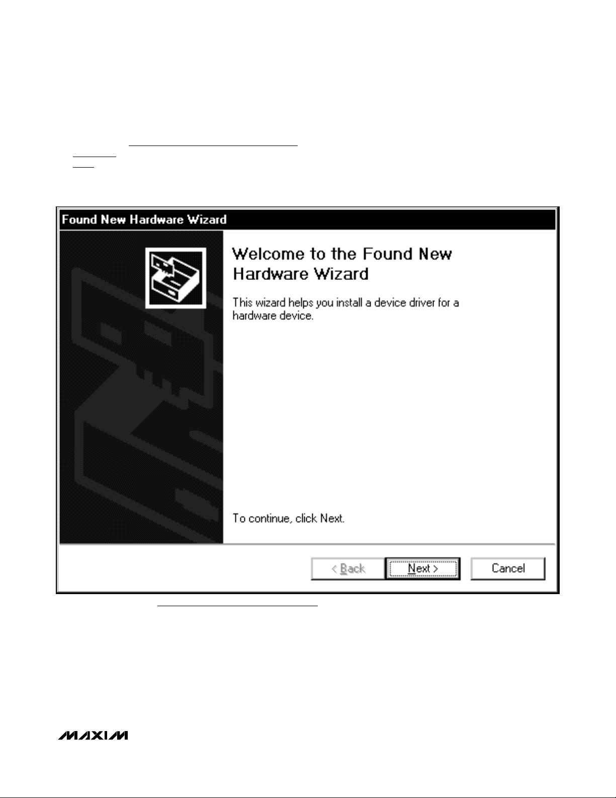
1) Once the USBTO232 board is connected to the PC
for the first time in Windows XP, a Found New
Hardware Wizard | Welcome window appears, as
shown in Figure 1. Choose the No, not this time
selection and press the Next button to get started. If
you do not see a window that is similar to the one
described above after 30 seconds, remove the USB
cable from the USBTO232 board and reconnect it.
Administrator privileges are required to install the USB
device driver on Windows 2000/XP.
Figure 1. Windows XP: Found New Hardware Wizard |Welcome Window
Page 4

USBTO232
2) A Found New Hardware Wizard | FTDI FT8U2XX
Device window (Figure 2) appears next. This win-
dow asks What do you want the wizard to do?.
Choose the Install from a list or specific location
(Advanced) option and press the Next button.
Figure 2. Windows XP: Found New Hardware Wizard | FTDI FT8U2XX Device Window
USB-to-COM Port Adapter Board User Guide
4 _______________________________________________________________________________________
Page 5
_______________________________________________________________________________________ 5
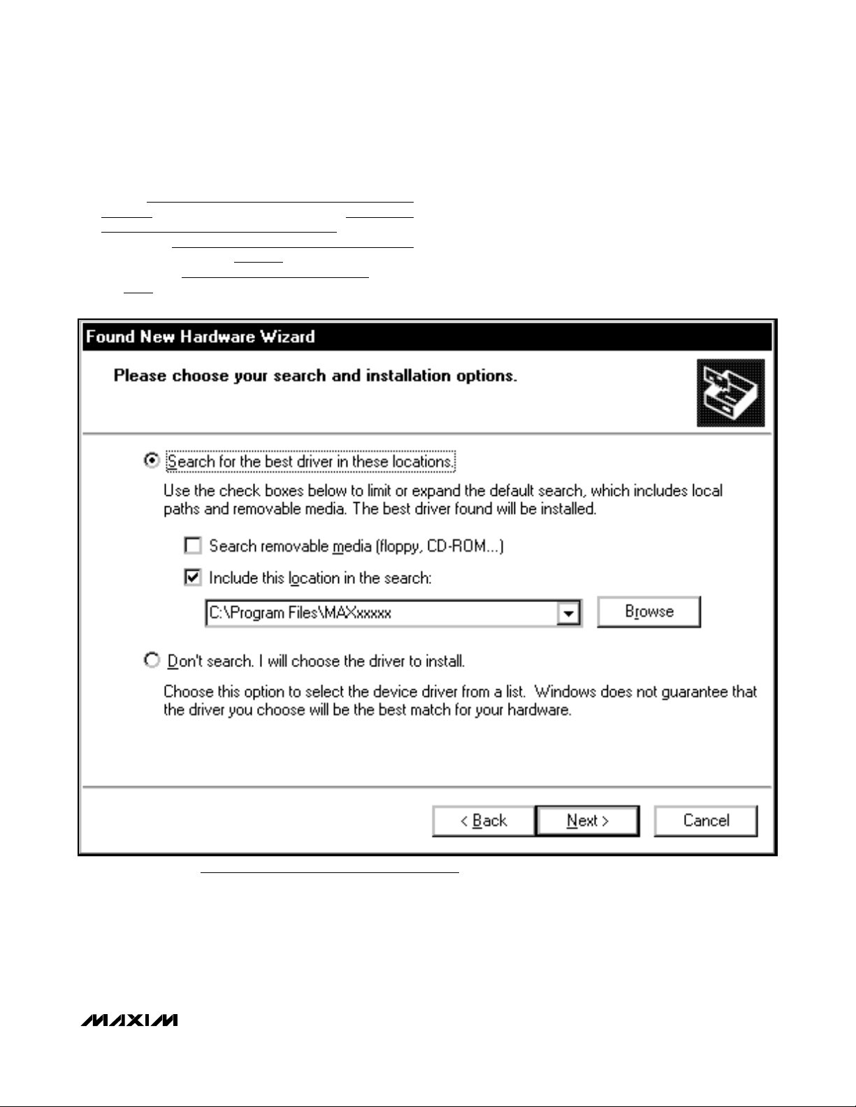
3) At the Found New Hardware Wizard | Search
Options window (Figure 3), choose the Search for
the best driver in these locations option and
check the Include this location in the search
checkbox. Press the Browse button and navigate
to the path: C:\Program Files\MAXxxxxx (where
xxxxx represents the Maxim IC part number on the
EV kit being evaluated). Press the Next button
when finished.
USBTO232
USB-to-COM Port Adapter Board User Guide
Figure 3. Windows XP: Found New Hardware Wizard | Search Options Window
Page 6

USBTO232
USB-to-COM Port Adapter Board User Guide
6 _______________________________________________________________________________________
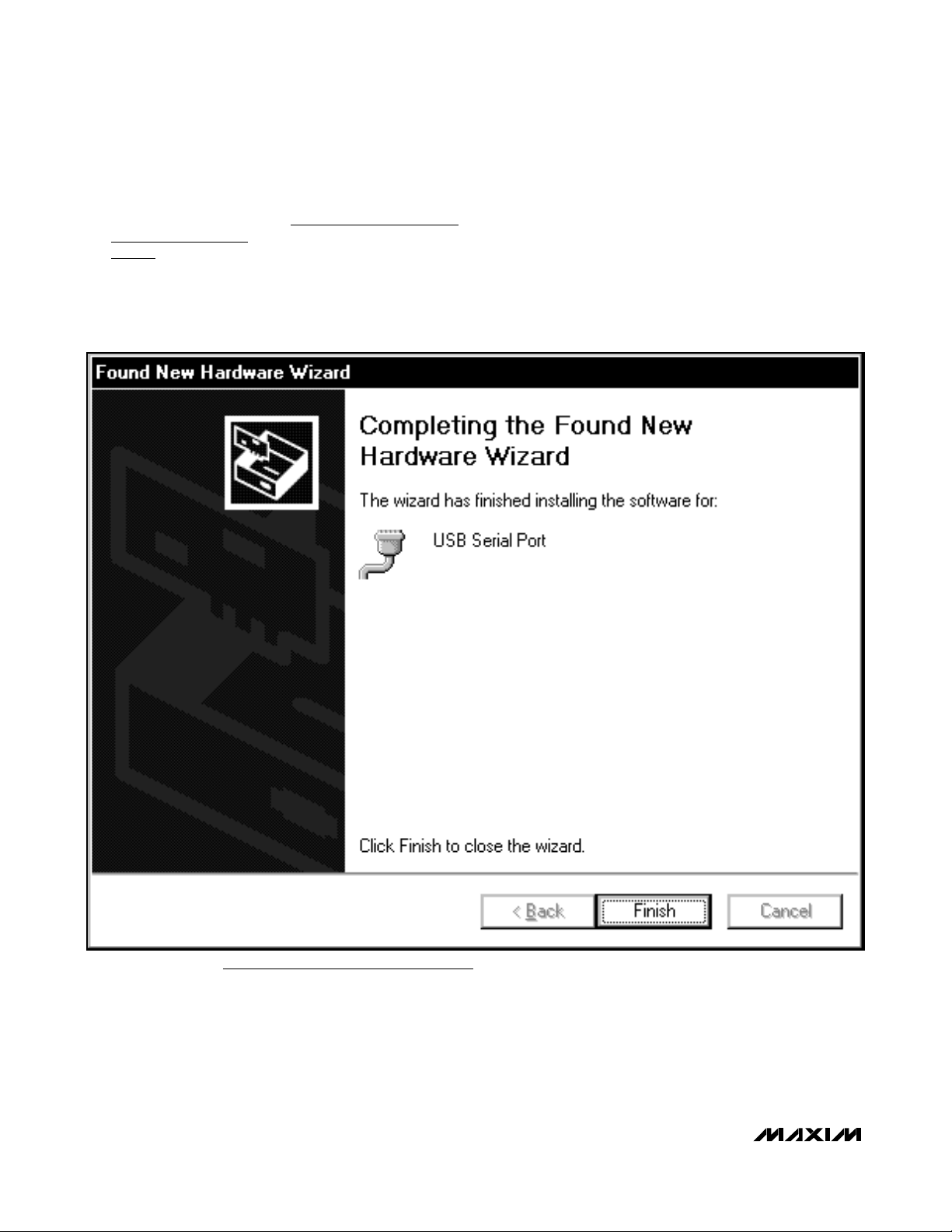
4) The Found New Hardware Wizard | Complete window appears (Figure 4). Press the Finish button.
Figure 4. Windows XP: Found New Hardware Wizard | Complete Window
Page 7

USBTO232
USB-to-COM Port Adapter Board User Guide
_______________________________________________________________________________________ 7
5) A Found New Hardware Wizard | Welcome window appears again (Figure 5). Choose the No, not
this time selection and press the Next button.
Figure 5. Windows XP: Found New Hardware Wizard | Welcome Window
Page 8
USBTO232
6) The next window is the Found New Hardware
Wizard | USB Serial Port window (Figure 6). This
window asks What do you want the wizard to
do?. Choose the Install from a list or specific
location (Advanced) option and press the Next
button.
USB-to-COM Port Adapter Board User Guide
8 _______________________________________________________________________________________
Figure 6. Windows XP: Found New Hardware Wizard | USB Serial Port Window
Page 9
7) At the Found New Hardware Wizard | Search
Options window (Figure 7), choose the Search for
the best driver in these locations option and
check the Include this location in the search
checkbox. Press the Browse button and navigate
to the path: C:\Program Files\MAXxxxxx. Press
the Next button when finished.
USBTO232
USB-to-COM Port Adapter Board User Guide
_______________________________________________________________________________________ 9
Figure 7. Windows XP: Found New Hardware Wizard | Search Options Window
Page 10
USBTO232
8) The next window is the Found New Hardware
Wizard | Complete window (Figure 8). Press the
Finish button.
9) When finished, return to step 8 of the USBTO232
Quick Start
section.
USB-to-COM Port Adapter Board User Guide
10 ______________________________________________________________________________________
Figure 8. Windows XP: Found New Hardware Wizard | Complete Window
Page 11

Windows 2000 USB Driver Installation
1) Once the USBTO232 board is connected to the PC
for the first time in Windows 2000, a Found New
Hardware window appears, as shown in Figure 9.
USBTO232
USB-to-COM Port Adapter Board User Guide
______________________________________________________________________________________ 11
Figure 9. Windows 2000: Found New Hardware Window
Page 12

USBTO232
2) A Found New Hardware Wizard | Welcome window
then appears (Figure 10). Press the Next button.
USB-to-COM Port Adapter Board User Guide
12 ______________________________________________________________________________________
Figure 10. Windows 2000: Found New Hardware Wizard | Welcome Window
Page 13

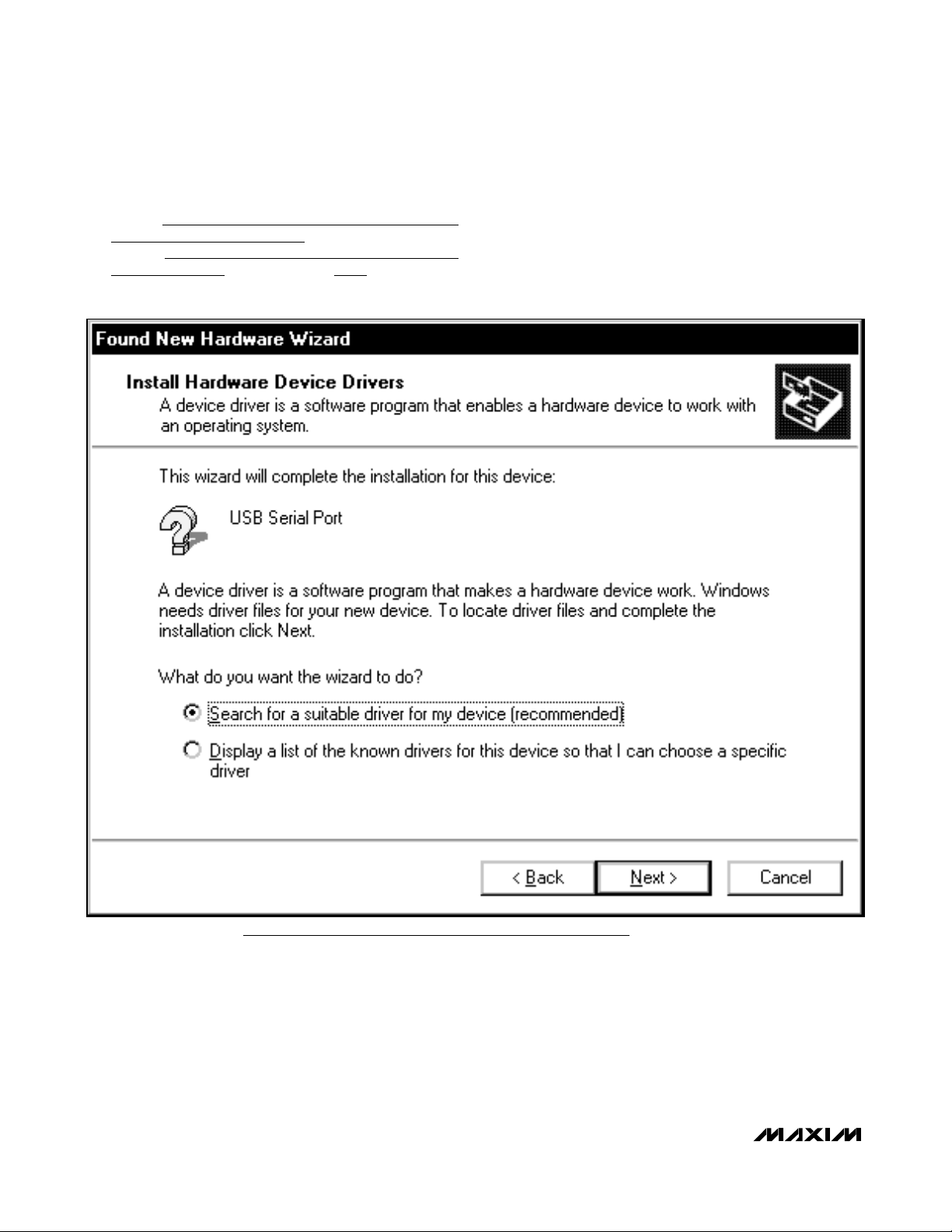
3) At the Found New Hardware Wizard | Install
Hardware Device Drivers window (Figure 11),
choose Search for a suitable driver for my device
(recommended) and press the Next button when
finished.
USBTO232
USB-to-COM Port Adapter Board User Guide
______________________________________________________________________________________ 13
Figure 11. Windows 2000: Found New Hardware Wizard | Install Hardware Device Drivers Window
Page 14

USBTO232
4) The Found New Hardware Wizard | Locate Driver
Files window appears next (Figure 12). Check the
Specify a location checkbox and press the Next
button when finished.
USB-to-COM Port Adapter Board User Guide
14 ______________________________________________________________________________________
Figure 12. Windows 2000: Found New Hardware Wizard | Locate Driver Files Window
Page 15

5) The next window is the Found New Hardware
Wizard | Path window (Figure 13). Press the
Browse button and choose the path C:\Program
Files\MAXxxxxx. Press the OK button when finished.
USBTO232
USB-to-COM Port Adapter Board User Guide
______________________________________________________________________________________ 15
Figure 13. Windows 2000: Found New Hardware Wizard | Path Window
Page 16

USBTO232
6) The Found New Hardware Wizard | Driver Files
Search Results window is shown in Figure 14. Press
the Next button after the wizard finds the driver.
USB-to-COM Port Adapter Board User Guide
16 ______________________________________________________________________________________
Figure 14. Windows 2000: Found New Hardware Wizard | Driver Files Search Results Window
Page 17

7) At the Found New Hardware Wizard | Complete
window (Figure 15), press the Finish button.
USBTO232
USB-to-COM Port Adapter Board User Guide
______________________________________________________________________________________ 17
Figure 15. Windows 2000: Found New Hardware Wizard | Complete Window
Page 18

USBTO232
8) A Found New Hardware window appears for the
USB Serial Port, as shown in Figure 16.
USB-to-COM Port Adapter Board User Guide
18 ______________________________________________________________________________________
Figure 16. Windows 2000: Found New Hardware Window
Page 19
9) When the Found New Hardware Wizard |
Welcome window appears (Figure 17), press the
Next button.
USBTO232
USB-to-COM Port Adapter Board User Guide
______________________________________________________________________________________ 19
Figure 17. Windows 2000: Found New Hardware Wizard | Welcome Window
Page 20
USBTO232
10) At the Found New Hardware Wizard | Install
Hardware Device Drivers window (Figure 18),
choose Search for a suitable driver for my device
(recommended) and press the Next button when
finished.
USB-to-COM Port Adapter Board User Guide
20 ______________________________________________________________________________________
Figure 18. Windows 2000: Found New Hardware Wizard | Install Hardware Device Drivers Window
Page 21

11) The Found New Hardware Wizard | Locate Driver
Files window (Figure 19) appears. Check the
Specify a location checkbox and press the Next
button when finished.
USBTO232
USB-to-COM Port Adapter Board User Guide
______________________________________________________________________________________ 21
Figure 19. Windows 2000: Found New Hardware Wizard | Locate Driver Files Window
Page 22

USBTO232
12) At the Found New Hardware Wizard | Path window (Figure 20), press the Browse button and
choose the path C:\Program Files\MAXxxxxx.
Press the OK button when finished.
USB-to-COM Port Adapter Board User Guide
22 ______________________________________________________________________________________
Figure 20. Windows 2000: Found New Hardware Wizard | Path Window
Page 23
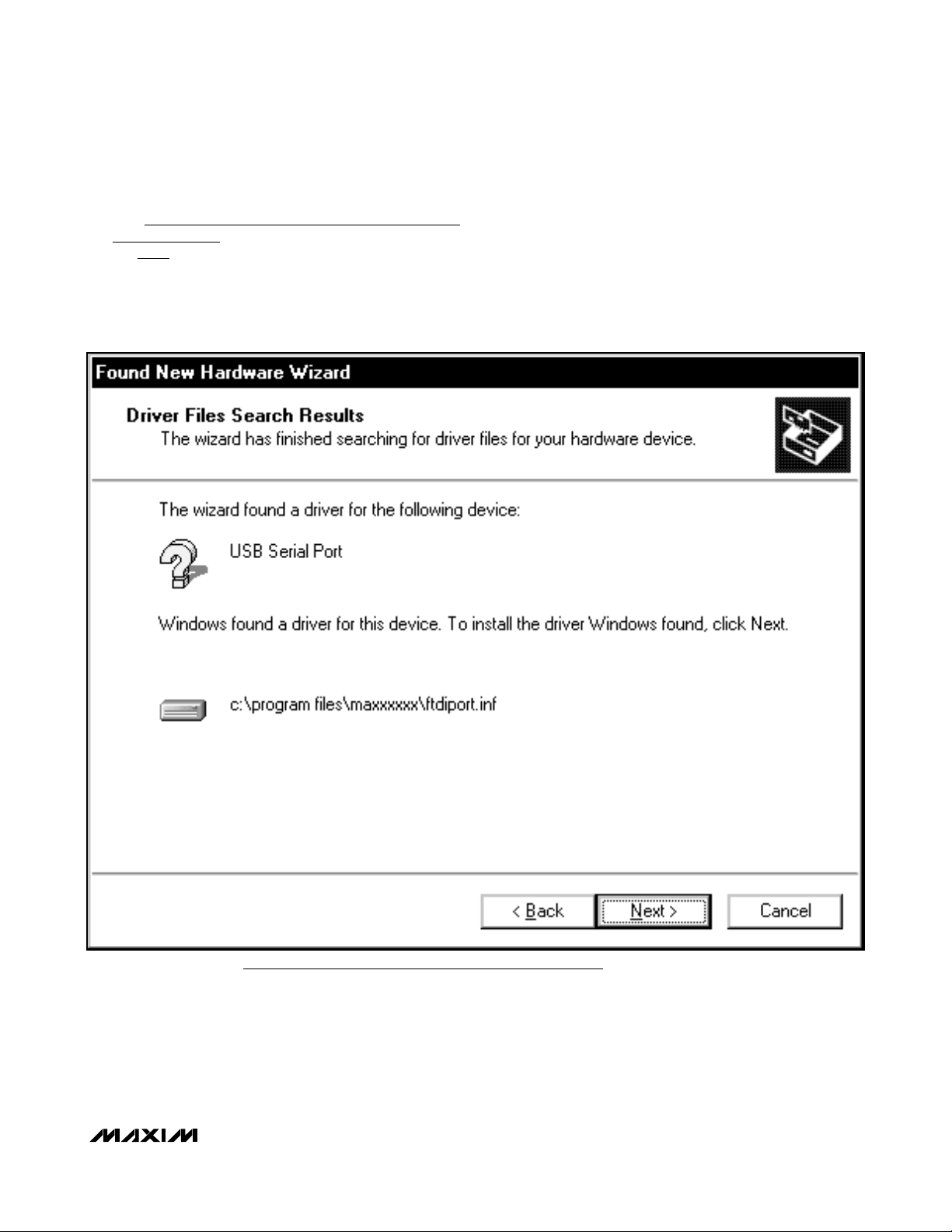
13) The Found New Hardware Wizard | Driver Files
Search Results window ( Figure 21) appears. Press
the Next button after the wizard finds the driver.
USBTO232
USB-to-COM Port Adapter Board User Guide
______________________________________________________________________________________ 23
Figure 21. Windows 2000: Found New Hardware Wizard | Driver Files Search Results Window
Page 24

USBTO232
14) The next window is the Found New Hardware
Wizard | Complete window (Figure 22). Press the
Finish button.
15) When finished, return to step 8 of the USBTO232
Quick Start
section.
USB-to-COM Port Adapter Board User Guide
24 ______________________________________________________________________________________
Figure 22. Windows 2000: Found New Hardware Wizard | Complete Window
Page 25

Windows 98SE USB Driver Installation
1) Once the USBTO232 board is connected to the PC
for the first time in Windows 98SE, an Add New
Hardware Wizard | Start window appears, as
shown in Figure 23. Press the Next button to get
started.
USBTO232
USB-to-COM Port Adapter Board User Guide
______________________________________________________________________________________ 25
Figure 23. Windows 98SE: Add New Hardware Wizard | Start Window
Page 26

USBTO232
2) An Add New Hardware Wizard | Options window
appears next (Figure 24). Choose the Search for
the best driver for your device (Recommended)
option and press the Next button when finished.
USB-to-COM Port Adapter Board User Guide
26 ______________________________________________________________________________________
Figure 24. Windows 98SE: Add New Hardware Wizard | Options Window
Page 27

3) At the Add New Hardware Wizard | Specify
Location window (Figure 25), check the Specify a
location checkbox and press the Browse button.
Choose the path C:\Program Files\MAXxxxxx\
R10906 (where xxxxx represents the Maxim IC part
number on the EV kit being evaluated). Press the
Next button when finished.
USBTO232
USB-to-COM Port Adapter Board User Guide
______________________________________________________________________________________ 27
Figure 25. Windows 98SE: Add New Hardware Wizard | Specify Location Window
Page 28

USBTO232
4) The Add New Hardware Wizard | Search window
appears (Figure 26). Press the Next button once
the driver has been located.
USB-to-COM Port Adapter Board User Guide
28 ______________________________________________________________________________________
Figure 26. Windows 98SE: Add New Hardware Wizard | Search Window
Page 29

5) The next window is the Add New Hardware Wizard
| Complete window (Figure 27). Press the Finish
button to complete the driver installation.
6) When finished, return to step 8 of the USBTO232
Quick Start
section.
USBTO232
USB-to-COM Port Adapter Board User Guide
______________________________________________________________________________________ 29
Figure 27. Windows 98SE: Add New Hardware Wizard | Complete Window
Page 30

USBTO232
USB-to-COM Port Adapter Board User Guide
30 ______________________________________________________________________________________
Figure 28. USBTO232 Schematic
P2
P2-1
P2-2
P2-3
P2-4
P2-5
P2-6
P2-7
P2-8
DB9 TYPE DTE
P2-9
23
6
3
RI
IN
R4
MAX213
IN
T2
RTS#
DSR
22
7
1
15
RI#
OUT
R4
IN
T1
TXD
USBDP
RTS
21
IN
T4
OUT
R1
8
9
DSR#
U1
DCD
RXDATA
CTS
27
28
IN
OUT
R3
T4
OUT
OUTT2OUT
T3
T1
1
2
DTR
TXDATA
VCC
DTR
TXDATA
CTS#
SLEEP#
VCC
26
24
25
EN
OUT
SHDN
R3
U2
IN
OUT
R2
R2
5
3
4
RTS
RXDATA
VCC30
5
RXD
3
JU1
2
4
VCCI0
1
USBDM
16
20
9
H1
FT232RL
N.C.
8
CTS
DTR#
19
IN
T3
IN
R1
VCC
DSR
H1-1
HEADER 8 PIN
VCC
20
VCC
24
DCD#
OUT
R5
11
N.C.
RI
C6
0.1µF
GND GND TEST
AGND GND
CBUS1
1
JU3
2
3
D2
3
2
JU2
1
D1
CBUS0
H1-8
25 7182126
DCD
18
IN
R5
CC
V
C10
1µF
C4
0.1µF
CBUS0
C12
0.1µF
OSCI
27
17V-16
13
H1-2
23
CBUS0
V+
12
CBUS1
28
C1+
22
OSCO
C7
C2-
C5
H1-3
CBUS1
0.1µF
14
0.1µF
CBUS2
12
15
C2+
H1-4
13
CBUS2
CBUS4
GND10C1-
CBUS3
10
14
DCD#
H1-5
CBUS3
VCC30
VCC
VCC30
6
17
RI#
H1-6
C11
3V3OUT
R2
270Ω
R1
270Ω
H1-7
RESET#
0.1µF
19
RESET#
CTS#
DTR#
2
11
VCC
P1
FB1
USB TYPE B
P1-1
C1
0.01µF
P1-2
C3
C2
47pF
P1-3
47pF
P1-4
SLEEP#
DCD#
RI#
CTS#
DTR#
VCC
C9
4.7µF
C8
0.1µF
Page 31

USBTO232
USB-to-COM Port Adapter Board User Guide
Maxim cannot assume responsibility for use of any circuitry other than circuitry entirely embodied in a Maxim product. No circuit patent licenses are
implied. Maxim reserves the right to change the circuitry and specifications without notice at any time.
Maxim Integrated Products, 120 San Gabriel Drive, Sunnyvale, CA 94086 408-737-7600 ____________________
31
© 2006 Maxim Integrated Products is a registered trademark of Maxim Integrated Products, Inc.
CARDENAS
Figure 29. USBTO232 Component Placement Guide—Component Side
Figure 30. USBTO232 PCB Layout—Component Side Figure 31. USBTO232 PCB Layout—Solder Side
 Loading...