

Page 1
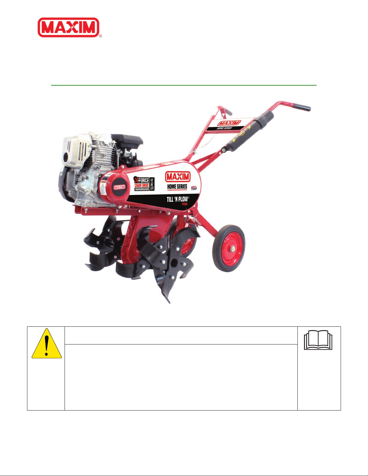
TP50H
WARNING
USE EXTREME CAUTION WHILE USING THIS EQUIPMENT. INJURY CAN OCCUR.
Owner’s Manual MTP50HA
READ CAREFULLY AND UNDERSTAND ALL ASSEMBLY AND SAFE OPERATION
INSTRUCTIONS BEFORE OPERATING. FAILURE TO FOLLOW THE SAFETY RULES
AND OTHER BASIC SAFETY PRECAUTIONS MAY RESULT IN SERIOUS PERSONAL
INJURY.
800-621-2798 TP50H Rev A Page 1
Page 2

TP50H
Table of Contents
1 INTRODUCTION ........................................................................................................................................................ 5
1.1 ... Benefits ....................................................................................................................................................................................5
1.2 ... Navigating This Manual ..................................................................................................................................................5
1.3 ... Warnings and Safety Precautions ..............................................................................................................................5
1.4 ... Operation References/Terminology ..........................................................................................................................7
1.5 ... Owner Assistance ................................................................................................................................................................7
1.6 ... Model Identification ..........................................................................................................................................................8
1.7 ... Further Assistance .............................................................................................................................................................8
2 SAFETY ......................................................................................................................................................................... 8
2.1 ... General Safety Rules ..........................................................................................................................................................8
2.2 ... PRODUCT-SPECIFIC SAFETY RULES ...................................................................................................................... 10
2.3 ... ENGINE SAFETY PRECAUTIONS .............................................................................................................................. 10
2.4 ... Safety Decals ...................................................................................................................................................................... 14
2.5 ... Training ............................................................................................................................................................................... 15
2.6 ... Preparation ........................................................................................................................................................................ 15
2.7 ... Operation ............................................................................................................................................................................ 15
2.8 ... Maintenance and Storage ........................................................................................................................................... 16
3 PARTS BREAKDOWN ........................................................................................................................................... 17
3.1 ... Tine Assembly Breakdown .......................................................................................................................................... 17
3.2 ... Frame Parts Breakdown .............................................................................................................................................. 18
3.3 ... Transmission Parts Breakdown ................................................................................................................................
3.4 ... Attachments Parts Breakdown ................................................................................................................................. 21
3.5 ... General Information ....................................................................................................................................................... 22
4 ASSEMBLY ................................................................................................................................................................ 22
4.1 ... Final Set-up ........................................................................................................................................................................ 26
5 OPERATING CONTROLS ..................................................................................................................................... 26
5.1 ... Speed ..................................................................................................................................................................................... 26
5.2 ... Depth of Tilling ................................................................................................................................................................. 26
5.3 ... Engage Lever ..................................................................................................................................................................... 26
20
6 OPERATION ............................................................................................................................................................. 27
6.1 ... Before Operating ............................................................................................................................................................. 27
6.2 ... Starting the Engine ......................................................................................................................................................... 27
800-621-2798 TP50H Rev A Page 2
Page 3

TP50H
6.3 ... Pre-Start .............................................................................................................................................................................. 28
6.4 ... Filling Fuel Tank .............................................................................................................................................................. 28
6.5 ... Checking and adding Oil .............................................................................................................................................. 28
6.6 ... Cold Starting Procedure ............................................................................................................................................... 29
6.7 ... Stopping Engine ............................................................................................................................................................... 29
6.8 ... Operation ............................................................................................................................................................................ 29
6.9 ... Operation Tips .................................................................................................................................................................. 31
6.10 . Tilling Pattern ................................................................................................................................................................... 31
7 ADJUSTMENTS........................................................................................................................................................ 31
7.1 ... Clutch Adjustment ........................................................................................................................................................... 32
7.2 ... Wheel Height Adjustment ............................................................................................................................................ 32
7.3 ... Tine Adjustment ............................................................................................................................................................... 32
8 Maintenance ............................................................................................................................................................ 33
8.1 ... Periodic Check ................................................................................................................................................................... 33
8.2 ... Engine Oil ............................................................................................................................................................................ 33
8.3 ... Dual Filter Element Air Cleaner ................................................................................................................................ 33
8.4 ... Cleaning the Cooling System ...................................................................................................................................... 34
8.5 ... Belt Replacement ............................................................................................................................................................. 34
8.6 ... Cleaning ............................................................................................................................................................................... 34
9 LUBRICATION ......................................................................................................................................................... 35
9.1 ... Wheels ................................................................................................................................................................................... 35
9.2 ... Clutch Lever Pivots.......................................................................................................................................................... 35
9.3 ... Transmission ..................................................................................................................................................................... 35
9.4 ... Idler Arms Pivot ................................................................................................................................................................ 35
10 STORAGE ................................................................................................................................................................... 35
10.1 . Engine ................................................................................................................................................................................... 35
10.2 . Tiller ...................................................................................................................................................................................... 35
11 TRANSPORTING ..................................................................................................................................................... 36
12 WARRANTY ............................................................................................................................................................. 37
12.1 . Warranty/Product Registration .............................................................................................................................. 37
800-621-2798 TP50H Rev A Page 3
Page 4

TP50H
⚠
READ ENTIRE MANUAL BEFORE ATTEMPTING TO OPERATE MACHINE
⚠
THE ENGINE EXHAUST FROM THIS PRODUCT CONTAINS CHEMICALS KNOWN TO THE STATE OF
WARNING
If incorrectly used, this machine can cause severe injury. Those who use and maintain this machine
should be trained in its proper use, warned of its dangers, and should read the entire manual before
attempting to set up, operate, adjust, or service this machine.
Read and keep this manual for future reference. This manual contains important information on
SAFETY, ASSEMBLY, OPERATION, AND MAINTENANCE. The owner must be certain that all the product
information is included with the unit. This information includes the MANUAL, the REPLACEMENT
PARTS and the WARRANTIES. This information must be included to make sure state laws and other
laws are followed. This manual should remain with the product even if it is resold.
WARNING
CALIFORNIA TO CAUSE CANCER, BIRTH DEFECTS OR OTHER REPRODUCTIVE HARMS.
IMPORTANT: This unit is equipped with an internal combustion engine and should not be used on or
near any unimproved forest-covered, brush covered, or grass-covered land unless the engine’s exhaust
system is equipped with a spark arrester meeting applicable local laws (if any). If a spark arrester is
used, it should be maintained in effective working order by the operator.
In the state of California, a spark arrester is required by law (section 4442 of the California public
resources code). Other states may have similar laws. Federal laws apply on federal lands. See your
authorized service center for a spark arrester.
800-621-2798 TP50H Rev A Page 4
Page 5

TP50H
1 INTRODUCTION
Maxim front tine tillers feature heavy gauge steel, heat treated tines, large 10” wheels and a
ruggedly built transmission. For additional durability, an extra heavy-duty frame. It’s this simple,
yet sturdy design that makes Maxim tillers low maintenance and easy to use.
Please read this entire manual before assembly and use. The manufacturer reserves the right
to change, alter or improve the product and this document at any time without prior notice.
1.1 Benefits
• Transmission case components have double welded flanged tine shaft bearing supports
for increased durability.
• Heavy-duty tines with bolt-on replaceable blades
• Heavy-duty steel wheels
• Heavy-duty frame
• Drag bar standard
1.2 Navigating This Manual
1. Use this manual to help familiarize yourself with safety, assembly, operation,
adjustments, troubleshooting, maintenance, specifications and warranty information. It
is very important that you read this manual and follow the instructions to ensure safe
operation of the attachment.
2. Please visit www.maximmfg.com
for updated information.
1.3 Warnings and Safety Precautions
The safety of our customers and other’s well-being is very important to us. Using this equipment
is an important responsibility. Accurate assembly and safe and effective use of the machine is the
owner’s responsibility.
• Read and follow all safety instructions
• Carefully follow all assembly instructions
• Maintain the machine according to the directions and schedule, included in this manual.
• Ensure that anyone who uses the machine is familiar with all controls and safety
precautions.
SPECIAL MESSAGES
Your manual contains special message to bring attention to potential safety concerns, machine
damage as well as helpful operating and servicing information. Please read all the information
carefully to avoid injury and machine damage. This information alerts you to potential hazards
that could hurt you or others.
800-621-2798 TP50H Rev A Page 5
Page 6
TP50H
⚠
⚠
WARNING INDICATED A HAZARD WHICH, IF NOT AVOIDED, COULD RESULT IN DEATH
⚠
CAUTION INDICATED YOU CAN BE HURT OR YOUR EQUIPMENT DAMAGED IF THE
⚠
CALIFONINA PROPOSITION 65 WARNING
NOTE: General information is given throughout the manual that may help the operator in the
operation or service of the machine.
You will find important safety information in a variety of forms, including:
1. Safety labels – on the tillers
2. Safety messages – preceded by a safety alert symbol
words: DANGER, WARNING, OR CAUTION.
These signal words mean:
DANGER: You will be killed or seriously injured if you don’t follow instructions
DANGER
WARNING: You can be killed or seriously injured if you don’t follow instructions.
WARNING
CAUTION: You can be injured if you don’t follow instructions.
OR SERIOUS INJURY AND/OR PROPERTY DAMAGE
⚠ and one of the three signal
CAUTION
SAFETY INSTUCTIONS THAT FOLLOW THIS SIGNAL WORD ARE NOT OBEYED.
WARNING
ENGINE EXHAUST FROM THIS PRODUCT CONTAINS CHEMICALS KNOWN TO THE STATE
OF CALIFORNIA TO CAUSE CANCER, BIRTH DEFECTS, OR OTHER REPRODUCTIVE HARM.
800-621-2798 TP50H Rev A Page 6
Page 7
TP50H
⚠
YOU MUST READ, UNDERSTAND AND COMPLY WITH ALL SAFETY AND OPERATING
Left
Right
WARNING
INSTRUCTIONS IN THIS MANUAL BEFORE ATTEMPTING TO SETUP AND OPERATE YOUR
MACHINE.
FAILURE TO COMPLY WITH ALL SAFETY AND OPERATIING INSTRUCTIONS CAN RESULT IN
LOSS OF MACHINE CONTROL, SERIOUS PERSONAL INJURY TO YOU AND/OR
BYSTANDERS, AND RISK OF EQUIPMENT AND PROPERTY DAMAGE. THE TRIANGLE IN THE
TEXT SIGNIFIES IMPORATNT CAUTIONS OR WARNINGS WHICH MUST BE FOLLOWED
⚠ This symbol points out important safety instructions which if not followed could endanger
your personal safety. Read and follow all instructions in this manual before attempting to
operate this equipment.
BEFORE OPERATING ENGINE:
Please read this section carefully. Read entire operating and maintenance instructions for this
product. Failure to follow instructions could result in serious injury or death. Operate the
machine according to the safety instructions outlined here and inserted throughout the text.
Anyone who uses this machine must read the instructions and be familiar with the controls.
Intended Use / Foreseeable Misuse
IMPORTANT: This is a motorized rotary tiller that works the soil by means of rotating tines. It is
pedestrian-controlled, but not self-propelled, with a gasoline-fueled internal combustion engine
to power the tines. It shall not be used for any other purpose.
1.4 Operation References/Terminology
References throughout this manual referred to as “Right” or “Left” are determined by being face-
standing behind tiller and facing the direction the unit will operate while in use.
1.5 Owner Assistance
Please complete the Warranty/Product Registration at the time of purchase. You will need to
complete the warranty/product registration form (pg. 39) with your new unit, or you may visit our
website www.maximmfg.com
this information, so we can keep you updated with any important information about your tiller
and provide you with the best customer service possible.
The parts and components used on your Maxim tiller have been specifically engineered for Maxim
tiller and should only be replaced with Maxim parts. Contact your local Maxim Dealer for OEM
replacement parts or contact our customer service department for assistance in parts, locating
your local servicing dealer and more. Your local dealer is equipped and trained to handle service
and repair for your tiller.
and complete our online product registration form. We require
800-621-2798 TP50H Rev A Page 7
Page 8
TP50H
Engine Serial Number
Tiller Serial Number
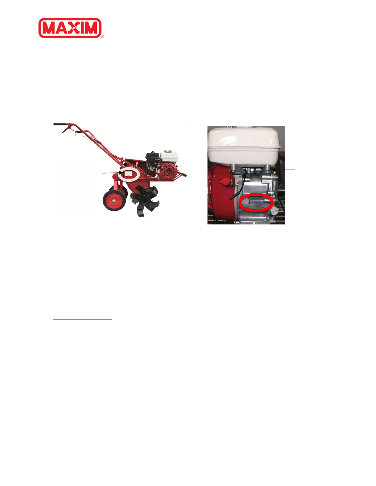
1.6 Model Identification
Please fill in your model and serial number below for future reference. This will help assist in
prompt service when ordering parts and service from your local Maxim Dealer.
Tiller Model No.___________________ Tiller Serial No. ______________________________
Engine Model No.__________________ Engine Serial No. _____________________________
Refer to the image below for location of your serial number plate:
1.7 Further Assistance
Your dealer and all of us at Maxim want you to be pleased with your tiller. Should you require
further assistance or have questions regarding your tiller, please contact your local dealer where
you purchased your tiller. If you are unable to satisfy your needs by your local dealer, please
contact us at:
Maxim
20195 South Diamond Lake Road, STE 100
Rogers, MN 55374
800-621-2789
www.maximmfg.com
2 SAFETY
2.1 General Safety Rules
• Read, understand and follow all instructions on the machine and in the manual(s). Be
thoroughly familiar with the controls and proper use of the machine before starting.
• Use this equipment for its intended purpose only.
• Familiarize yourself with all of the safety and operating decals on this equipment and on
any of its attachments or accessories.
• Do not put hands or feet near or under rotating parts.
800-621-2798 TP50H Rev A Page 8
Page 9

TP50H
• Only allow responsible individuals who are familiar with the instructions to operate the
machine. Do not allow children to operate this machine. Do not allow adults to operate
the machine without proper instruction.
• Thoroughly inspect the area where the machine is to be used and remove all foreign
objects. Your equipment can propel small objects at high speed causing personal injury or
property damage. Stay away from breakable objects, such as house windows,
automobiles, greenhouse, etc.
• Wear appropriate clothing such as sturdy, rough-soled shoes (steel toe recommended)
and close-fitting pants and shirt. Loose fitting clothes or jewelry can be caught in moving
parts. Never wear shorts. Never wear sandals, sneakers or open shoes, and never
operate the machine with bare feet.
• Do not wear loose clothing or jewelry. They can get caught in moving parts. Always keep
hands, feet, hair and loose clothing away from any moving parts on engine and machine.
• Always wear safety goggles or safety glasses with side shields when operating the
machine to protect your eyes from foreign objects which can be thrown from the unit.
• Always wear a protective hearing device.
• Always wear work gloves and sturdy rugged soled footwear. Wear footwear that will
improve footing on slippery surfaces. Leather work shoes or short boots work well for
most people. These will protect the operator’s ankles and shins from small sticks,
splinters, and other debris.
• It is advisable to wear protective headgear to prevent the possibility of being struck by
small flying particles, or being struck by low hanging branches, twigs or other objects
which may be unnoticed by the operator.
• Do not operate the machine without proper guards or other safety protective devices in
place.
• See manufacturer’s instructions for proper operation and installation of accessories. Only
use accessories approved by the manufacturer.
• Operate only in daylight.
• Do not operate product when fatigued or under the influence of alcohol, drugs or other
medication which can cause drowsiness or affect your ability to operate machine safely.
• Never operate machine in wet grass. Always be sure of your footing; keep a firm hold on
the handle and walk; never run.
• Watch for traffic when operating tiller near, or when crossing roads.
• If the equipment should start to vibrate abnormally, stop the engine (motor), flip the
ON/OFF switch, located on engine, to the OFF position.
• Regularly inspect the machine. Make sure parts are not bent, damaged or loose.
• Temperature of muffler and nearby areas may exceed 150° F (65° C). Allow muffler and
engine areas to cool before touching.
• Never pick up or carry the machine while the engine is running.
800-621-2798 TP50H Rev A Page 9
Page 10

TP50H
• Prolonged exposure to noise and vibration from gasoline engine-powered equipment
should be avoided. Take intermittent breaks and/or wear ear protection from engine
noise as well as heavy work gloves to reduce vibration in hands.
• Keep all screws, nuts and bolts tight.
• Do not transport the machine from one place to another with the engine running.
• Always turn off fuel supply valve on engine before transport.
• When moving the packaged machine, always do so with a partner.
• Check local regulations for age restrictions on use of this machine.
2.2 PRODUCT-SPECIFIC SAFETY RULES
• Do not till above underground utilities, including water lines, gas lines, electric cables or
pipe. Contact appropriate utility representatives to determine if/where electrical
cables, gas lines, water lines, etc. are buried BEFORE operation.
• Do not operate the machine on terrain/soil with large rocks and foreign objects which can
damage the equipment.
• After striking a foreign object, stop the engine. Flip the ON/OFF switch, located on engine,
to the OFF position. Inspect the machine for damage. If damaged, repair before starting
and operating the machine.
• The tines of the tiller should not rotate when the engine is idling. If they do, contact your
local dealer or Maxim technical service for instruction.
• If an object becomes lodged in the tines, flip the ON/OFF switch, located on engine, to the
OFF position, then allow the machine to cool before attempting to remove the foreign
object.
• The idler and belt will transfer maximum power after about two hours of normal
operation. During this break-in period clutch slippage may occur. The clutch should be
kept free of oil or other moisture for efficient operation.
2.3 ENGINE SAFETY PRECAUTIONS
⚠ Warning Carbon Monoxide Poisoning
Engines give off carbon monoxide, an odorless, colorless, poisonous gas. Carbon monoxide may
be present even if you do not smell or see any engine exhaust. Breathing carbon monoxide can
cause nausea, fainting or death, in addition to drowsiness, dizziness and confusion. If you
experience any of these symptoms, seek fresh air and medical attention immediately.
800-621-2798 TP50H Rev A Page 10
Page 11

TP50H
⚠
E
⚠
WARNING
NGINES GIVE OFF CARBON MONOXIDE, AN ODORLESS, COLORLESS, POISONOUS GAS. CARBON MONOXIDE
MAY BE PRESENT EVEN IF YOU DO NOT SMELL OR SEE ANY ENGINE EXHAUST
MONOXIDE CAN CAUSE NAUSEA, FAINTING OR DEATH, IN ADDITION TO DROWSINESS, DIZZINESS AND
CONFUSION.
IF YOU EXPERIENCE ANY OF THESE SYMPTOMS, SEEK FRESH AIR AND MEDICAL ATTENTION IMMEDIATELY.
. BREATHING CARBON
CAUTION
HOT GASES ARE A NORMAL BY-PRODUCT OF A FUNCTIONING INTERNAL COMBUSTION ENGINE. FOLLOW
ALL SAFETY INSTRUCTIONS TO PREVENT BURNS AND FIRES
DO NOT ALTER/MODIFY ENGINE:
NEVER ALTER OR MODIFY THE ENGINE FROM THE FACTORY. SERIOUS INJURY OR DEATH MAY OCCUR IF
ENGINE IS MODIFIED OR ALTERED.
.
WHEN WORKING ON OR REPLACING PARTS FOR THE ENGINE OR PRODUCT, YOU MUST ALWAYS FLIP THE
/OFF SWITCH TO THE OFF POSITION.
ON
PREVENTING CARBON MONOXIDE POSIONING
• Always start and run engine outdoors. Do not start or run engine in an enclosed area,
even if doors or windows are open.
• Never try to ventilate engine exhaust indoors. Carbon monoxide can reach dangerous
levels very quickly.
• Never run engine outdoors where exhaust fumes may be pulled into a building.
• Never run engine outdoors in a poorly ventilated area where the exhaust fumes may be
trapped and not easily taken away. (Examples include: in a large hole or areas where hills
surround your working area.)
• Never run engine in an enclosed or partially enclosed area. (Examples include: buildings
that are enclosed on one or more sides, under tents, car ports or basements.)
• Always run the engine with the exhaust pointed in the direction away from the operator.
• Never point the exhaust towards anyone. People should always be a minimum of ten feet
away from the operation of the engine and its attachments.
• Do not change the engine governor settings or over-speed the engine.
800-621-2798 TP50H Rev A Page 11
Page 12

TP50H
GASOLINE FIRES AND HANDLING FUEL SAFELY
⚠ Warning gasoline is highly flammable and explosive
You can be burned or seriously injured when handling fuel. Use extreme care when handling
gasoline or other fuels. They are flammable, and vapors are explosive.
• When storing extra fuel be sure that it is in an appropriate
container and away from any fire hazards.
• Prevent fire and explosion caused by static electric discharge.
Use only nonmetal, portable fuel containers approved by the
Underwriter’s Laboratory (U.L.) or the American Society for
Testing & Materials (ASTM).
• Always fill fuel tank outside in a well-ventilated area. Never fill
fuel tank with fuel indoors. (Examples include: basement, garage,
barn, shed, house, porch, etc.) Never fill tank near appliances
with pilot lights, heaters, or other ignition sources. If the fuel has
to be drained, this should be done outdoors. The drained fuel should be stored in a
container specifically designed for fuel storage or it should be disposed of carefully.
• Never remove the fuel cap or add fuel with the engine running. Stop engine and allow to
cool before filling.
• Do not smoke while using engine or around fuel.
• Never drain fuel from engine in an enclosed area.
• Always wipe up excess (spilled) fuel from engine before starting. Clean up spilled fuel
immediately. If fuel is spilled, do not start the engine but move product and fuel container
from area. Clean up spilled fuel and allow to evaporate and dry after wiping and before
starting.
• Allow fuel fumes/vapors to escape from the air before starting the engine.
• Test the fuel cap for proper installation before starting and using engine.
• Always run the engine with fuel cap properly installed on the engine.
• Never smoke while refilling engine fuel tank.
• Do not store engine with fuel in fuel tank indoors. Fuel and fuel vapors are highly
explosive.
• Never pour fuel from engine fuel tank.
• Never siphon fuel by mouth to drain fuel tank.
• Always have an adult fill the fuel tank and never allow children to fill the engine.
• Never allow anyone under the influence of drugs or alcohol to fill the engine.
• When storing gasoline or equipment with fuel in the tank, store away from furnaces,
stoves, water heaters or other appliances that have a pilot light or other ignition source
because they can ignite gasoline vapors.
800-621-2798 TP50H Rev A Page 12
Page 13

TP50H
BURNS AND FIRES
The muffler, muffler guard and other parts of the engine become extremely hot during the
operation of the engine. These parts remain extremely hot after the engine has stopped.
• Never remove the muffler guard from the engine.
• Never touch the muffler guard because it is extremely hot and will cause severe burns.
• Never touch parts of the engine that become hot after operation.
• Always keep materials and debris away from the muffler guard and other hot parts of the
engine to avoid fires.
CHILDREN AND BYSTANDERS
Tragic accidents can occur if the operator is not alert to the presence of children and/or
bystanders. Never assume that others will remain where you last saw them.
• Keep the area of operation clear of all persons, especially small children and pets. Keep
children under the watchful care of a responsible adult.
• Be alert and turn machine off if children enter the area.
• Before and while moving backwards, look behind and down for small children.
• Never allow children to operate the machine.
• Use extra care when approaching blind corners, shrubs, trees, or other objects that may
obscure vision.
SERVICE
• Always stop the engine whenever you leave the equipment, before cleaning, repairing or
inspecting the unit. Engine should be turned off and cool. Never make adjustments or
repairs with the engine (motor) running. Flip the ON/OFF switch, located on engine, to
the OFF position to prevent accidental starting.
• Always wear eye protection when you make adjustments or repairs.
• Keep all nuts and bolts tight and keep equipment in good condition.
• Never tamper with safety devices. Check their proper operation regularly.
• When servicing or repairing the machine, do not tip the machine over or up unless
specifically instructed to do so in this manual. Service and repair procedures can be done
with the machine in an upright position. Some procedures will be easier if the machine is
lifted on a raised platform or working surface.
• To reduce fire hazard, keep machine free of grass, leaves or other debris build-up. Clean
up oil or fuel spillage. Allow machine to cool before storing.
• Stop and inspect the equipment if you strike an object. Repair, if necessary, before
restarting.
• Clean and replace safety and instruction decals as necessary.
800-621-2798 TP50H Rev A Page 13
Page 14

TP50H
Item # 366720
Item # 336784
Item # 336776
Item # 336777
Item # 799546
Item # ZS001
Item # 336799
Item # 87108
• To guard against engine over-heating, always have engine air filter mounted and clean.
• Inspect machine before storage. When not in use, flip the ignition ON/OFF switch, located
on engine, to the OFF position and store indoors in a dry place locked or otherwise
inaccessible to children.
• Use only original equipment parts from the factory, including all nuts and bolts.
2.4 Safety Decals
This Tiller has been designed and manufactured to provide you the safety and reliability you
would expect from an industry leader in outdoor power equipment manufacturing.
Reading this manual and the safety instructions it contains will provide you with the necessary
basic knowledge to operate this equipment safely and effectively. We have placed safety decals
on the tiller to remind you of some of this important information while you are operating the unit.
These important safety decals are illustrated below and are shown here to help familiarize you
with the content of the safety messages you will see as you perform normal tilling operations.
Please review these decals now, and if you have any questions regarding its meaning or how to
comply with these instructions, reread the complete safety instruction text in this manual, or
contact your local dealer.
Should a decal become unreadable because of being worn, faded or otherwise damaged during
the use of your tiller; please use the part number information provide to order a replacement
label. These decals are easily applied and will act as a constant visual reminder to you, and others
who may use the equipment, to follow the safety instructions necessary for safe, effective
operation of your tiller.
800-621-2798 TP50H Rev A Page 14
Page 15

TP50H
2.5 Training
1. Read the Owner’s Manual carefully. Be thoroughly familiar with the controls and the
proper use of the equipment. Know how to stop the unit and disengage the tines quickly.
2. Never allow children to operate the equipment. Never allow adults to operate the
equipment without proper instructions.
3. Keep the area of operation clear of all persons, particularly small children and pets.
4. Always stay alert. Watch what you are doing and use common sense. Do not operate unit
when fatigued.
5. Understand the use of all tiller controls.
2.6 Preparation
1. Thoroughly inspect the area where the equipment is to be used and remove all foreign
objects.
2. Disengage the idler before starting the engine (motor).
3. Always wear substantial footwear and long pants. Do not operate the equipment when
barefoot or wearing open sandals.
4. Wear ear and eye protection. Eye protection must meet applicable CE requirements. To
avoid hearing damage, we recommend hearing protection be worn whenever using the
equipment.
5. Handle fuel with care; it is highly flammable.
6. Use an approved fuel container.
7. Never add fuel to a running engine or hot engine.
8. Fill fuel tank outdoors with extreme care. Never fill fuel tank indoors.
9. Replace gasoline cap securely and clean up spilled fuel before starting.
10. Never attempt to make any adjustments while the engine (motor) is running.
2.7 Operation
1. Do not put hands or feet near or under rotating parts.
2. Exercise extreme caution when operating on or crossing gravel drives, walks, or roads.
Stay alert for hidden hazards or traffic. Do not carry passengers.
3. After striking a foreign object, stop the engine (motor) by turning the ON/OFF switch,
located on engine, to OFF, thoroughly inspect the tiller for any damage, and repair the
damage before restarting and operating the tiller.
4. Exercise caution to avoid slipping or falling.
5. If the unit should start to vibrate abnormally or make unusual noise, stop the engine
(motor) and check immediately for the cause. Vibration is generally a warning of trouble.
6. Stop the engine (motor) when leaving the operating position.
7. Take all possible precautions when leaving the machine unattended. Disengage the tines
and stop the engine by turning the ON/OFF switch, located on engine, to OFF.
800-621-2798 TP50H Rev A Page 15
Page 16

TP50H
8. Before cleaning, repairing, or inspecting, shut off the engine and make certain all moving
parts have stopped. Disconnect the spark plug wire and keep the wire away from the plug
to prevent accidental starting.
9. Do not run the engine indoors; exhaust fumes are dangerous.
10. Never operate the tiller without proper guards, plates, or other safety protective devices
in place.
11. Keep children and pets away when operating.
12. Do not overload the machine capacity by attempting to till too deep or too fast.
13. Never operate the machine at high speeds on slippery surfaces. Look behind and use care
when backing up.
14. Never allow bystanders near the unit.
15. Use only attachments and accessories approved by the manufacturer of the tiller.
16. Never operate the tiller without good visibility or light.
17. Be careful when tilling in hard ground. The tines may catch in the ground and propel the
tiller forward. If this occurs, let go of the handlebars and do not restrain the machine.
2.8 Maintenance and Storage
1. Keep machine, attachments, and accessories in safe working conditions.
2. Check assembly pins, engine mounting bolts, and other bolts at frequent intervals for
proper tightness to be sure the equipment is in safe working condition.
3. Never store the machine with fuel in the fuel tank inside a building where ignition sources
are present, such as hot water and space heaters, clothes dryers, etc. allow the engine to
cool before storing in any enclosure.
4. Always refer to the storage instructions (Section 10) for important details if the tiller is to
be stored for an extended period.
800-621-2798 TP50H Rev A Page 16
Page 17

TP50H
REF #
QTY
PART #
DESCRIPTION
1
16
80049
BOLT, HEX, 3/8-16 X 1.00, ZINC
2
16
86383
NUT, NYLOCK, 3/8-16, GR5, ZINC
4 4 130762
R.H. SLASHER BLADE
5 4 130763
L.H. SLASHER BLADE
6 2 130776
INNER HUB - WELDMENT (SLASHER)
7 2 130777
OUTER HUB-SLASHER TINE (PARTS)
3 PARTS BREAKDOWN
3.1 Tine Assembly Breakdown
800-621-2798 TP50H Rev A Page 17
Page 18

TP50H
Cross Brace Decal
Belt Guard Decal
Part # 88175
Made In USA Decal
Part # 797158
3.2 Frame Parts Breakdown
800-621-2798 TP50H Rev A Page 18
Part # 88174
Page 19

TP50H
REF #
QTY
PART #
DESCRIPTION
2 3 80027
BOLT,HHCS,1/4-20 X 1/2,GR5,ZINC
4 4 80045
BOLT, HHCS, 5/16-18 X 2 3/4, GR5,
6 2 80206
WASHER, SAE, 3/8, ZINC
7 3 80212
1/4 USS FLAT WASHER - ZINC
8 5 86101
5/16 NYLON LOCK NUT
10 1 87268
5/16-18 X 5/16 SETSCREW ZN
11 1 87269
3/16 X 3/4 WOODRUFF KEYK9N
12 1 87282
BOLT,HHCS,5/16-18 X 2.25,GR5,ZINC
13 2 87330
NUT, JAM, 3/8-24, ZINC
15 3 87373
NUT, CLIP, 1/4-20, 0025-015, BLACK
16 2 87422
3/8-24 NYLOCK NUT
17 1 87433
SPRING, .055 WDIA, 0.75 ID, 1.5-0.35
18 1 87435
PULLEY, 9" X 5/8"
19.1 4 80031
1/4-20 X 1-1/2 HEX SCREW GR 5-ZINC
19.2 6 85128
1/4" NYLON LOCK NUT
19.3 1 87416
SPRING, EXTENSION
19.4 2 87274
5/16-18 X 3 3/4 CAP SCREW
19.5 4 80205
5/16 SAE FLAT WASHER - ZINC
19.6 4 86101
5/16 NYLON LOCK NUT
19.7 2 87374
P-CLIP, 3/8 X 9/16, GAL
19.8 4 87265
PIN, CLEVIS, 3/8, 2-1/4, ZINC
19.9 2 86115
5/16-18 X 1-1/4 HEX SCREW GR 5-
19.10 1 87438
HOLDER, MANUAL, SMALL
19.11 2 85015
BOLT, HEX, 1/4-20 X 2, GR 5, ZINC
19.12 1 80193
1/4-20 X 1/2 THRD CUT HEX - ZINC
19.13 1 80212
1/4 USS FLAT WASHER - ZINC
19.14 1 80214
WASHER, 5/16, USS, ZINC
19.15 1 87568
ASSY, CABLE, CLUTCH
19.17 4 87264
HAIRPIN, RU, 3/8-7/16, 1-7/8, ZINC
20 1 88172
KIT, DECAL SHEET, TP50H
24.1 1 313786
HANDLE GRIP, 1
24.2 1 130688
TUBE, HANDLE, TILLER
25 2 130701
HITCH CASTING
26 1 162069
IDLER SHAFT, TILLER
27 2 336678
BRACE. HANDLE BAR - PAINT (TP)
28 1 336686
DEPTH BAR - PAINT (MT,GM,TP)
REF #
QTY
PART #
DESCRIPTION
30 1 338009
IDLER PULLEY, 1-7/8" X 3/8"
31 1 359216
LOWER BRACKET, BELT GRD -BEND
32 2 359311
SPACER, TRANS
33 1 359325
LEVER, IDLER - CUT/PUNCH
34 1 461469
PIN, DEPTH BAR ADJ. (TP)
35 1 500002
FRAME RAIL ASSEMBY LH
36 1 500003
FRAME RAIL RIGHT HAND
37.1 1 500059
WLD, YOKE
37.2 1 87279
PIN, COTTER, 7/64 X 1.00, ZINC
37.3 1 86755
PIN-L-1/2 X4 Zn-CLR
37.4 1 80207
WASHER, FLAT, 1/2 SAE, ZINC
37.5 1 87428
SPRING, 0.055 WDIA, 0.579 ID, 1.575
37.13 2 162031
WHEEL, 10" X 1.75" (REG)
37.14 2 444719
NUT, JAM, NYLOCK, 3/8" NC, ZN
37.15 2 359330
WHEEL SHOULDER BOLT 2 5/16"
38 1 500108
ASSY, BELT GUARD, TP50H
39.1 1 313786
HANDLE GRIP, 1
39.2 1 87372
POST, BINDING, 0.25 X 1.25, ZINC
39.3 1 87425
BOLT, MS #10-24 X 3.125
39.6 1 336683SD
CLUTCH LEVER - PAINT
39.7 1 130688SD
TUBE, HANDLE, TILLER
40.1 1 130683-
A
CROSS BRACE - PAINT
40.2 1 88174
DECAL, HANDLE BRACE
44 1 87333
BELT, 4L51
45 1 130450
TRANSMISSION, W/GREASE
46.3 2 80196
5/16 LOCK WASHER - ZINC
46.4 2 86667
BOLT,HHCS,5/16-24 X 3/4,GR5,ZINC
46.7 1 500053
WELDMENT, BELT GUIDE
46.9 1 88146
ENG 160CC HONDA HORIZ. GC160
46.10 1 87332
2 X 3/4 C/SHAFT PULLEY
46.11 2 87268
5/16-18 X 5/16 SETSCREW ZN
46.12 1 86454
KEY-SQUARE 3/16 X 1
47 4 87460
BOLT-HF-5/16-18 X 1.5 Gr5 Z
48 4 87463
NUT, NYLOCK, FLG, 5/16-18, GRF, ZP
800-621-2798 TP50H Rev A Page 19
Page 20

TP50H
ITEM
QTY
PART #
DESCRIPTION
A
1
130450-SP
Complete Transmission
A1 1 80045
BOLT HHCS 5/16-18 X 2 3/4 GR5 ZINC
A2
23
80150
5/16-18 SERRATED FLANGE NUT
A3
23
86022
BOLT, HHFB, 5/16-18 X 0.50, GR 5, Z
A4 1 86101
5/16 NYLON LOCK NUT
A5 1 87346
SPACER INPUT SHAFT
A6 1 88113
ZERK, GREASE 1/4-28
A7
20 oz
88115
GREASE- LITHIUM, NLGI "0"
A8 1 130693
L.H. CASE SIDE
A9 1 162023
IDLER SPROCKET CLUSTER
A10 1 162037
INPUT SHAFT/SPROCKET (35A13)
A11 1 162038
OUTPUT SHAFT/SPROCKET(50A22)
A12 1 336675
GASKET, CASE
A13 2 359293
BUSHING, INPUT (AA811)<BRONZE>
A14 1 359296
CHAIN, #35 X 70 LINKS
A15 2 359297
IDLER BEARING, #SCH912
ITEM
QTY
PART #
DESCRIPTION
A16 1 359298
BUSHING, IDLER CLUSTER
A17 2 359299
WASHER, TRANSMISSION -FORM
A18 1 359302
CHAIN, #50 X 44 LINKS
A19 1 359303
OUTPUT SHAFT SPACER-FORM
A20 2 359304
BEARING #SCE2016, OUTPUT SHAFT
A21 2 359305
OIL SEAL. OUTPUT SHAFT
A22 2 359306
DUST SHIELD -FORM
A23 1 359310
PLUG, EXPANSION
A24
AS REQ.
359313
WASHER,.062 X 2OD X 1.265"ID"
A25
AS REQ.
359314
WASHER,.0375 X 2"OD X 1.265"ID
A26
AS REQ.
359315
WASHER, .020 X 2"OD X 1.265"ID
A27
AS REQ.
455049
WASHER, SHIM 41/64 X 1 X .0625
A28
AS REQ.
455062
WASHER, SHIM 41/64"X 1"X .032"
A29 1 500080
WELD, TRANS, COVER, RH
A30 1 88122
O-RING-5/8-7/8-1/8
A46 1 87108
DECAL-CHAINCASE GREASE
A
3.3 Transmission Parts Breakdown
800-621-2798 TP50H Rev A Page 20
Page 21

TP50H
ITEM
QTY
PART #
DESCRIPTION
C1.1
8
80172
1/2-13 HEX NUT
C1.2
11
400238
1/2-13 X 1-1/4 HEX SCREW GR 5-ZINC
C1.3
8
80199
1/2" LOCK WASHER
C1.4
2
461466
PIN, CLEVIS, 3/8, 2-1/4, ZINC
C1.5
2
460312
HAIRPIN, RU, 3/8-7/16, 1-7/8, ZINC
C1.6
2
87325
7/16 -14 X 2 PLOW BOLT
C1.7
4
80167
7/16-14 STEEL HEX NUT GR5 ZP
C1.8
4
80216
WASHER, USS, 7/16, ZINC
C1.9
1
80055
BOLT, HHCS, 3/8-16 X 2-1/2, GR5, ZINC
C1.10
6
443110
NUT, HEX, 3/8-16, GR5, ZINC
C1.11
3
80215
3/8 FLAT USS WASHER ZINC
C1.12
1
400267
BOLT, HHCS, 3/8-16 X 2, GR5, ZINC
C1.13
7
446142
WASHER, LOCK, 3/8, ZINC
C1.14
4
80231
7/16 LOCK WASHER
C1.15
4
87384
BOLT, PLOW 3/8-16 X 1 1/2 ZP
C1.16
2
87385
PLOW BOLT 7/16-14 X 2 1/2 ZP
C1.17
1
359330
WHL SHLDR BOLT 3/8-16 2 HHFLG ZP
C2
1
130709
WHEEL, 8" X 1.50" <REG> (M30B)
C3
2
130724
WHEEL HUB 16 IN PULL WHEEL
C4
2
130725
INSIDE EXTENSION - PAINTED
C5
1
162005-L
WHEEL, 16" (4.80 X 400 X 8), LEFT
C6
1
162005-R
WHEEL, 16" (4.80 X 400 X 8), RIGHT
C7
1
336695
8 INCH FURROWER
C8
1
336697
7" TURN SHOVEL, R.H.
C9
1
336698
7" TURN SHOVEL, L.H.
C10
6
336700
SHANK
C11
3
336701
ADJUSTMENT BRACKET
C12
4
336703
REVERSABLE CULTIVATOR BLADE
C13
1
336704
TOOL HOLDER
C14
1
336705
TOOL BAR
C15
1
336706-A
15" DEPTH ROD
3.4 Attachments Parts Breakdown
800-621-2798 TP50H Rev A Page 21
Page 22

TP50H
3.5 General Information
Engine Honda GC160 Engine
Transmission Chain Drive
Tine speed (max) 72 RPM
Tines
Tilling width 14” or 26”
Tilling depth Up to 10”
Drag Bar Heavy-Duty w/ Spring Loaded Pin
Handles 1”-14 Gauge Tubular Steel
Hitch Precision Cast Hitch w/ Spring Loaded Pin
Tires 10 x 1.75 (for transport only)
Dimensions (L x W x H) 57” x 24” x 39”
Shipping weight 200 lbs.
Heat-Treated Slasher Tines w/ Replaceable
Blades
4 ASSEMBLY
Prior to assembling your tiller, make sure that you have a clear work space and that there are no
missing parts.
1. Remove the tiller from the box. Do not attempt to lift the tiller from the box. After
opening the top, remove manuals and all unassembled parts including the parts bag and
protective packaging. Place these parts off to the side for later assembly. Carefully cut all
four sides of the box and lay the sides flat on the floor as shown below. Temporarily leave
the tiller resting on the top of the boxes containing the tines & accessories, while moving
through the first few steps of assembly.
800-621-2798 TP50H Rev A Page 22
Page 23

TP50H
Handle Bar Tie
Braces
Upper Cable
Lower Cable
Guide
Belt guard
bracket
Cable loop end
Handle Bars
Clutch
Cable
Idler Pulley Lever
Guide
Left side – Right side
1. Install right and left handle bars to the frame using two 5/16” x 3 ¾ ” hex bolts, nylon lock
nuts and four flat washers one on each side of the handle, two per bolt. Do not tighten
any bolts until all bolts have been inserted with lock nuts. Be sure the handle bar, having
the Clutch engagement lever is on the right side, as you stand in an operating position.
800-621-2798 TP50H Rev A Page 23
Page 24

TP50H
Handle Bar
Cross Brace
Manual
Tube
2. Refer to the previous illustration for more clarity. Install the two handle bar tie braces
using the holes in the transmission and the lower holes in the handle bars. Fasten the
braces to the transmission using two 5/16” x 1 ¼” hex bolts and nylon lock nuts. The left
brace, bolts between the belt guard bracket, and the transmission. It may be necessary to
loosen belt guard to assist in aligning the handle brace bolt holes, going through belt
guard bracket and transmission. Mount the lower Cable guide using the rear mounting
bolt and place on the opposite side of the belt guard bracket, as shown.
3. Noting previous illustration, the upper handle bar tie braces are mounted to the inside of
the handle bars. The upper clutch cable guide mounts on the inside of the right handle
bar along with the upper handle bar tie brace. Use two ¼” x 1 ½” bolts and nylon lock nuts
secure one on each side as shown.
4. Install the handle bar cross brace between the handle bars using one ¼” x 2” and 5/16”
flat washer for manual tube mounting upper left side, three ¼ - x 1 ½” hex bolts for the
remaining three cross brace mounts, use nylon lock nuts for all four.
5. Tighten all bolts at this time, with the exception of the upper manual tube bolt.
6. Finalize the manual tube mounting by aligning bottom mounting hole to the hole in the
handle and secure lower end of tube by installing ¼” washer and self-tapping ¼” x ½” pan
screw. Tighten both upper and lower manual tube mounting bolts.
7. Route the clutch cable through guides with the cable loop end at the Idler Pulley Lever as
shown in the previous illustration. Hook cable loop end directly on to idler pulley lever.
800-621-2798 TP50H Rev A Page 24
Page 25

TP50H
1
2
3
4
8. Connect the clutch cable with the adjustment-chain at the top. Use the spring to connect
the handle lever to the clutch cable chain as illustrated above. The chain links are used for
clutch cable adjustment. The clutch cable should be adjusted so that the belt will slip
when released and the spring will be extended ¼”- ½” when lever is engaged. Ensure the
clutch cable operates smoothly when releasing and compressing lever.
9. Using extreme caution to slowly roll unit off of the box, then tip the unit back on to the
handle bars as illustrated below and begin to mount the digging tines.
800-621-2798 TP50H Rev A Page 25
Page 26

TP50H
10. Install tine assemblies on shaft and lock in place using 4 tine pins and 4 cotter hair pins. Be
sure that all cutting edges are facing toward the front as they rotate. You may need to
use rubber mallet to gently tap tine sub-assemblies onto tine shaft.
11. Once tines are all pinned, unit can be brought upright, to rest on the tines and wheels.
4.1 Final Set-up
1. The transmission is filled with NLGL “00” grease at factory and
should not require service other than annually. See section 9.3 for
transmission information.
2. Remove the engine dipstick and fill crankcase with oil according to
engine owner’s manual.
NOTE: Engine is shipped from factory without oil. You must add
engine oil before starting engine. If engine is started without oil
engine may be damaged beyond repair and will not be covered by warranty.
3. Fill the fuel tank. Use clean, fresh, lead-free gasoline. Fill the tank completely. DO NOT
MIX OIL WITH GASOLINE.
5 OPERATING CONTROLS
5.1 Speed
1. The tiller will dig deeper and move forward slower by pushing down on the handles.
2. The tiller will go ahead faster but at a shallower depth by raising the handles.
3. The speed of the tines is controlled by the throttle control lever mounted on engine.
5.2 Depth of Tilling
1. The proper throttle speed and correct up and down hand pressure on the handles must
be used.
2. Raising up means going forward, this action releases the grip of the drag stake in the soil,
allowing the tiller to progress ahead.
3. Pushing down means slowing down or even standing still. This directs the drag stake into
the soil, thus holding the tiller back.
4. Adjust throttle for desired speed and depth of tines.
5.3 Engage Lever
The clutch is disengaged when clutch lever is away from handle grip. To engage clutch, depress
clutch lever to handle.
800-621-2798 TP50H Rev A Page 26
Page 27

TP50H
6 OPERATION
6.1 Before Operating
1. Check your tiller. Be sure all bolts are tight. After several hours of operating and at
periodic maintenance intervals, check all fasteners and tighten securely as required.
2. Check oil and fill according to the engine owner’s manual.
⚠ WARNING: Engine is shipped from factory without oil. You must add engine oil before
starting engine. If engine is started without oil engine may be damaged beyond repair and will
not be covered by warranty.
3. Read engine manual for full instructions and safety warnings.
4. Place tiller on level ground.
5. Remove dipstick. Wipe with clean cloth.
6. Reinsert dipstick (do not screw dipstick back in). Remove dipstick and check.
7. Oil should be at FULL level.
8. If oil is required, add slowly. Recheck level.
9. Change oil if contaminated.
10. Tighten dipstick and clean around oil fill area before starting.
11. Fill engine with clean unleaded gasoline according to the engine owner’s manual.
⚠ WARNING: Gasoline is flammable. Use caution when handling or storing gasoline. Never fill
the gas tank while the engine is running or hot. Allow the engine to cool before adding gas. Clean
any spilled gasoline.
12. Check the air cleaner element. Ensure that the air filter is clean and maintained according
to engine owner’s manual
13. Familiarize yourself with all operating controls.
⚠ DANGER: Never operate the tiller without proper guards, plates, or other safety devices in
place. Serious injury or death could result.
⚠ WARNING: Do not attempt to start or operate this tiller until you are completely familiar with
location and use of each control necessary to operate this tiller. You must know how to stop this
machine before you start it. Each time prior to starting, check the throttle control lever to ensure
it is working properly.
6.2 Starting the Engine
Before starting the engine, check the machine against the Set-Up instructions (section 4) to see
that it is properly assembled. Review the safety suggestions and operating instructions for safe
and proper use of the tiller.
800-621-2798 TP50H Rev A Page 27
Page 28

TP50H
⚠
6.3 Pre-Start
1. Check the spark plug wire for proper connection on the spark plug.
2. Fill the fuel tank with clean, fresh, regular gasoline from a sealed
container.
3. Check the oil for proper level.
4. Make certain clutch lever is in disengaged position.
6.4 Filling Fuel Tank
We recommend the use of clean, fresh, lead-free gasoline. The use of leadfree gasoline results in few combustion deposits and longer valve life. Do not
fill fuel tank completely, allow space for fuel to expand. Provide
approximately ¼” of tank space for fuel expansion.
1. Shut-off engine and allow engine to completely cool before refilling the fuel tank.
2. Move to a well-ventilated area, outdoors, away from flames and sparks.
3. Clean debris from area around the fuel cap.
4. Loosen fuel cap slowly. Prevent the cap from coming in contact with dirt or debris.
5. Carefully add fuel without spilling.
6. Do not fill gas tank completely full, allow space for fuel to expand.
7. Immediately replace fuel cap and tighten. Wipe off spilled fuel to allow it to dry before
starting engine.
CAUTION
ENGINE IS SHIPPED FROM FACTORY WITHOUT OIL. YOU MUST ADD ENGINE OIL BEFORE STARTING ENGINE. IF ENGINE IS
STARTED WITHOUT OIL, ENGINE MAY BE DAMAGED BEYOND REPAIR AND WILL NOT BE COVERED BY WARRANTY.
NEVER STORE ENGINE WITH FUEL IN THE TANK INDOORS. FUEL AND FUEL VAPORS ARE HIGHLY FLAMMABLE.
AN ADULT ONLY MUST ALWAYS HANDLE AND FILL THE ENGINE WITH FUEL.
ALWAYS HANDLE GAS IN A WELL-VENTILATED AREA, OUTDOORS, AWAY FROM FLAMES OR SPARKS.
DO NOT START ENGINE IF FUEL IS SPILLED. WIPE OFF EXCESS FUEL AND ALLOW TO DRY. REMOVE ENGINE FROM AREA TO
AVOID SPARKS.
6.5 Checking and adding Oil
1. Be sure the engine is located on a level surface before checking or refilling oil. Clean
around oil fill area.
2. Be sure engine is cool.
3. Unscrew dipstick and wipe clean with cloth.
4. Reinsert dipstick (do NOT thread for accurate reading).
800-621-2798 TP50H Rev A Page 28
Page 29

TP50H
⚠
ENGINE MUST BE ON LEVEL SURFACE WHEN CHECKING OIL LEVEL OR FILLING WITH OIL.
5. Remove and check dipstick. If no oil shows on the dipstick, refill so that the oil level
appears between the low and high marks on the dipstick.
6. Change oil if contaminated.
*NOTE: See engine Owner’s Manual for proper oil maintenance instructions
IMPORTANT
FAILURE TO DO SO CAN RESULT IN OVERFILLING THE ENGINE WITH OIL WHICH WILL
IMPAIR THE ENGINE’S PERFORMANCE.
6.6 Cold Starting Procedure
1. Move throttle control lever, located on engine, to center position.
2. Move choke control located on engine to choke position. Hold the handle with your left
hand while pulling the starter rope with your right. Pull the rope out slowly until the
engine reaches the start of the compression cycle (the rope will pull slightly harder at this
point). Then allow the rope to retract fully.
3. Pull the rope with a continuous full arm stroke. Keep a firm grip on the starter handle and
let the rope rewind slowly. Do not let the handle snap back against the starter.
4. Repeat steps number 2-3 above until engine starts. If engine fails to start after 3 pulls on
the rope, repeat step number 1 above as necessary. Slowly move choke control, located
on engine, to RUN position after engine has responded and engine warms up.
5. As the engine warms up, move the throttle lever to full throttle position. Allow engine
warm-up period before operating tiller.
⚠ NOTE: A warm engine may start without choking. Do not use the choke if engine is hot.
6.7 Stopping Engine
1. Move the throttle control to idle position.
2. Turn ON/OFF switch, located on engine, to off position.
3. Disconnect the wire from the spark plug to prevent accidental starting of the machine
while it is unattended.
6.8 Operation
⚠ IMPORTANT: Keep hands clear of belt and tines while engine is running.
⚠ WARNING: For safe operation, the chain drive must disengage immediately when clutch lever
is released. If it does not, adjust belt and cable tension as described in Section 7 in this manual.
Never leave the tiller unattended with the engine running.
800-621-2798 TP50H Rev A Page 29
Page 30

TP50H
⚠
To prevent personal injury, the chain drive must disengage immediately when clutch
⚠
Keep hands clear of belt and tines while engine is running. Never attempt to adjust or
DANGER
lever is released. If it does not, stop the tiller, adjust belt and cable tension as described
in Adjustments section of this manual. Never leave the tiller unattended with the engine
running. Children are attracted to a running tiller and could be injured if struck by the
rotating tines.
WARNING
clean tines while engine is running, at risk of sever injury.
1. When ground is hard (especially during spring and fall plowing), place wheels in up
position by pulling the spring-loaded locking pin from the wheel yoke and repositioning
the wheel frame bar allowing the spring-loaded pin to reposition and lock wheels in the
up position. For weeding or cultivation, wheels may be left down if you prefer.
2. Adjust the drag stake for comfortable operation. This is done by pulling the spring-loaded
locking pin from the drop stake locking hub and sliding the drag stake down or up. The
drag stake should be set so that when it is firmly in the ground, and your hands are on the
tiller handle, your arms hand comfortably with the elbows slightly bent.
3. Move the throttle control, located on engine, to center position. Start the engine and
allow it to warm up, then set the throttle at about half speed. After you have become
familiar with the tiller, you may want to run the engine a little faster.
4. Press down firmly on the handles and squeeze the clutch lever. The tines will begin to
turn, but the tiller should not move forward. If it does, don’t pull backwards – merely
press down harder on the handles. When you find the right amount of downward
pressure so that the tines are digging, and the tiller is not moving forward, release the
pressure slightly. As you release it, you’ll notice the tiller beginning to move forward.
⚠ NOTE: The whole tilling operation is controlled by the amount of pressure you put on the drag
stake. Do not fight the tiller. Stand between the handles and press down to go slower and dig
deeper and release the downward pressure to move forward faster. In normal soil, the actual up
and down movement of the handles will be no more than an inch or two.
800-621-2798 TP50H Rev A Page 30
Page 31

TP50H
⚠
To avoid possible serious bodily injury, when performing any adjustments, remove the
6.9 Operation Tips
To acquire the knack of letting the tiller do the work without effort on the part of the operator,
we offer the following suggestions:
1. Adjust drag stake so the handles are at such a height that your arms hang straight down
to contact them. Rear wheels should be in up position for deep tillage or ease of turning
in confined areas.
2. Operate the tiller at about ¾ throttle.
3. Don’t hurry the job – proceed at a slow walk – give the machine time to do its job.
4. Concentrate on keeping your arms relaxed (There is a natural tendency for any beginner
to tense up). Operating the tiller actually takes very little effort. Let the tiller do the work.
5. When tilling on sloping ground, turn the front of the machine uphill to sufficiently
counteract the tendency to run downhill.
6. For best results, operate at reduced throttle settings when ground is extremely hard or
rough.
7. Tighten all nuts and bolts periodically.
6.10 Tilling Pattern
1. Whenever possible till the soil in the direction in which the planting or rows will run. If the
soil is extremely hard and dry, it may be advisable to till across the plot on the first digging
and then obtain the depth you want by tilling in the direction the planting will be done.
7 ADJUSTMENTS
DANGER
spark plug wire and place the wire away from the plug to prevent accidental starting.
800-621-2798 TP50H Rev A Page 31
Page 32

TP50H
⚠
To avoid possible serious bodily injury, when performing any adjustments, remove the
7.1 Clutch Adjustment
Proper clutch adjust is very important. Minor adjustment, if needed, can be made by using the
links on the clutch cable chain only. However, the friction type clutch may need further
adjustments as the “V” belt wears. Adjust as follows:
1. Remove belt guard.
2. Loosen 4 engine mount bolts. Slide engine forward or backwards as required.
3. Unhook clutch cable from load spring.
4. Push upward on idler pulley to take all slack from the drive belt. Distance between the
inside of belt at the idler pulley should be between 2 7/8 and 3 1/8 of an inch.
5. Ensure pulleys are aligned with a long straight edge.
6. Retighten engine mounting bolts (17 foot lbs. of torque).
7. Remove all the slack from clutch cable and hook spring in proper chain link.
8. Check your adjustment by starting the tiller and holding the tines off the ground. If the
tines turn without any hand pressure on the engage lever, the adjustment is too tight.
Unhook the clutch load and hook into next chain link to lengthen clutch cable. If the cable
spring on the clutch handle doesn’t stretch when you hold the clutch handle all the way
in, the adjustment is too loose. Unhook spring end from chain and hook next link to
shorten clutch cable.
7.2 Wheel Height Adjustment
1. Wheel position may be adjusted. To place wheels in up position, pull the spring-loaded
locking pin from the wheel yoke and repositioning the wheel frame bar allowing the
spring-loaded pin to reposition and lock wheels in the up position. For weeding or
cultivation, wheels may be left down if you prefer.
7.3 Tine Adjustment
The standard tilling width is 26” with both inner and outer tine assemblies mounted. Tilling width
is 14” with outer assemblies removed.
1. To remove outer tine assemblies from inner tine assemblies, remove pin clip from clevis
pin.
2. Slide clevis pin out and remove outer tine assembly.
DANGER
spark plug wire and place the wire away from the plug to prevent accidental starting.
800-621-2798 TP50H Rev A Page 32
Page 33

TP50H
8 Maintenance
⚠ DANGER: To avoid possible serious bodily injury, when performing any adjustments, remove
the spark plug wire and place the wire away from the plug to prevent accidental starting.
8.1 Periodic Check
1. Regularly check all bolts and nuts for tightness.
2. If the belt begins to bottom out on the engine pulley, then replacement of the pulley is
needed. This is noticeable by the pulley “V” bottom becoming shiny.
8.2 Engine Oil
1. Check the oil level before starting the engine and after every five hours of operation.
2. Be sure engine is cool.
3. Before removing the filer plug, clean the area around it to prevent dirt from entering the
oil fill hole.
4. The engine should be in a level position when checking the oil.
5. Remove the filler plug and fill the crankcase with oil.
6. Use a high-quality detergent oil – refer to your engine owner’s manual for oil
requirements.
7. Add oil as necessary to keep oil level as indicated. Detergent oils keep the engine cleaner
and reduce the formation of gum and varnish deposits. Nothing should be added to the
recommended oil.
8. Change the oil after the first 20 hours of operation and every 100 hours there-after or
every 6 months, whichever comes first. Always change oil while the engine is warm. Oil
may be drained through the oil drain port towards the bottom of the engine. Refer to
your Engine Owner’s Manual for complete details.
8.3 Dual Filter Element Air Cleaner
Clean cartridge at three-month intervals or every 50 hours, whichever occurs first.
⚠ NOTE: Service more often under dust conditions.
1. Remove the wing nut from the air cleaner cover and remove cover.
2. Remove the wing nut from the air filter and remove the filer.
3. Remove the foam filter from the paper filter.
4. Inspect both air filter elements and replace them if they are damaged.
5. Always replace the paper air filter element at 300 hours.
⚠ NOTE: Replace or clean cartridge included with DUAL ELEMENT AIR CLEANER yearly or every
300 hours as described in CARTRIDGE AIR CLEANER. Service more often if necessary.
800-621-2798 TP50H Rev A Page 33
Page 34

TP50H
8.4 Cleaning the Cooling System
1. Remove blower housing and clean regularly.
⚠ NOTE: Grass or chaff may clog cooling system after prolonged service. Continued operation
with a clogged cooling system causes severe overheating and possible engine damage.
8.5 Belt Replacement
The drive belt located on the left side of the machine. To replace a worn or slipping belt proceed
as follows:
⚠ DANGER: To avoid possible serious bodily injury, when performing any adjustments, remove
the spark plug wire and place the wire away from the plug to prevent accidental starting.
1. Remove belt guard.
2. Make sure clutch lever is in disengaged position.
3. Start at the top of 10” pulley and begin removing belt in clockwise direction (facing tiller
from left side). If tension on belt is too great the idler pulley may be pulled downward to
relieve pressure on belt.
4. Once belt is off 10” pulley, remove it from smaller pulley.
5. Replace belt by reversing sequence of steps above.
6. Replace belt guard.
8.6 Cleaning
⚠ IMPORTANT: If the engine has been running, allow it to cool for at least half an hour before
washing.
1. Wash the tiller, including the underside, after use.
2. Wash the engine by hand and be careful to prevent water or debris from entering the air
cleaner.
⚠ NOTE: Do not use a garden hose or pressure washing equipment, it can force water into the
air cleaner. Water in the air cleaner will soak the filter element and can enter the carburetor or
engine cylinder, causing damage.
3. After washing the tiller, wipe dry.
4. After the tiller is clean and dry, touch up any damaged paint and coat other areas with a
light film of oil.
5. Wipe the tines with oil or spay to prevent rusting.
800-621-2798 TP50H Rev A Page 34
Page 35

TP50H
9 LUBRICATION
9.1 Wheels
Lubricate wheels and wheel support shafts once a month or every 40 operation hours with #30
oil. Apply oil to axle and hub at back of wheel. Spin to allow oil to move into bearings.
In extremely dusty conditions, wheels may become tight because of dust in bearing area. When
this condition occurs, remove the wheels. Clean axle and wheel bearing surfaces with solvent or
emery cloth, then oil and reassemble.
9.2 Clutch Lever Pivots
Apply a Few drops of SAE 30 oil to the clutch hand lever and idler lever pivots as required to
maintain a free and smooth operation of clutch.
9.3 Transmission
Transmission grease zerk is located on the upper right-hand side. Use Lithium NLGI “0” grease
when servicing the transmission. Annually, add grease if needed, being mindful not to overfill
and by pass lower shaft seals. If excessive grease seepage appears around tine rotor shaft, then
replace the output shaft seals and shields. Disassembly of transmission is not required to replace
the output shaft seals and shields. Should disassembly be required, please note: 1) Use shims
359313, 359314, 359315 as required for output shaft fitment. 2) Use shims 455062, 455049 as
required for input shaft fitment. 3) Add 20 oz of grease to inside of case once all components are
installed. 4) Torque cover fasteners to 8 ft-lbs. (96 in-lb.)
Note: Use part # 109386.MAX grease for service and maintenance. Other greases may not be
compatible and cause damage to the transmission and void warranty.
9.4 Idler Arms Pivot
Lubricate idler arm pivots once a month or every 40 operating hours with #30 oil.
10 STORAGE
10.1 Engine
1. If your tiller is to be stored over 30 days, please see your Engine Owner’s Manual for
storage information. The engine should be completely drained of fuel to prevent gum
deposits from forming on essential carburetor parts, fuel filter, fuel lines and tank.
2. Refer to engine manual for further engine storage procedures.
10.2 Tiller
1. At the end of the season or if tiller is to be stored for any length of time it should be
cleaned following the cleaning instructions in Section 8.6.
800-621-2798 TP50H Rev A Page 35
Page 36

TP50H
11 TRANSPORTING
To transport tiller from garden to storage area:
1. Move the throttle control to idle position.
2. Turn ON/OFF switch, located on engine, to OFF position.
3. Turn fuel supply valve/lever off, located on engine, to shut off fuel supply.
4. Place wheels in down position by pulling the spring-loaded locking pin from the wheel
yoke and repositioning the wheel frame bar allowing the spring-loaded pin to reposition
and lock wheels in the up position.
5. Raise drag stake. This is done by pulling the spring-loaded locking pin from the drop stake
locking hub and sliding the drag stake up.
800-621-2798 TP50H Rev A Page 36
Page 37

TP50H
12 WARRANTY
12.1 Warranty/Product Registration
Please register your product immediately after purchase. You can do that by visiting our
website at www.maximmfg.com
and complete our online product registration.
Or, complete the following warranty/production registration form on the next page and
return to:
Maxim
Attn: Warranty Registration Department
20195 South Diamond Lake Road, STE 100
Rogers, MN 55374
800-621-2798 TP50H Rev A Page 37
Page 38

TP50H
Or, Fax completed form to: 763-428-4821
800-621-2798 TP50H Rev A Page 38
Page 39

TP50H
800-621-2798 TP50H Rev A Page 39
Page 40

TP50H
Maxim
20195 South Diamond Lake Road
Suite 100
Rogers, MN 55374
www.maximmfg.com
800-621-2789
800-621-2798 TP50H Rev A Page 40
 Loading...