

Page 1

For pricing, delivery, and ordering information, please contact Maxim/Dallas Direct! at
1-888-629-4642, or visit Maxim’s website at www.maxim-ic.com.
_________________General Description
The MAX961–MAX964/MAX997/MAX999 are low-power,
ultra-high-speed comparators with internal hysteresis.
These devices are optimized for single +3V or +5V
operation. The input common-mode range extends
100mV Beyond-the-Rails™, and the outputs can sink
or source 4mA to within 0.52V of GND and VCC.
Propagation delay is 4.5ns (5mV overdrive), while supply current is 5mA per comparator.
The MAX961/MAX963/MAX964 and MAX997 have a
shutdown mode in which they consume only 270µA
supply current per comparator. The MAX961/MAX963
provide complementary outputs and a latch-enable feature. Latch enable allows the user to hold a valid comparator output. The MAX999 is available in a tiny
SOT23-5 package. The single MAX961/MAX997 and
dual MAX962 are available in space-saving 8-pin µMAX
packages.
________________________Applications
Single 3V/5V Systems
Portable/Battery-Powered Systems
Threshold Detectors/Discriminators
GPS Receivers
Line Receivers
Zero-Crossing Detectors
High-Speed Sampling Circuits
____________________________Features
♦ Ultra-Fast, 4.5ns Propagation Delay
♦ Ideal for +3V and +5V Single-Supply Applications
♦ Beyond-the-Rails Input Voltage Range
♦ Low, 5mA Supply Current (MAX997/MAX999)
♦ 3.5mV Internal Hysteresis for Clean Switching
♦ Output Latch (MAX961/MAX963)
♦ TTL/CMOS-Compatible Outputs
♦ 270µA Shutdown Current per Comparator
(MAX961/MAX963/MAX964/MAX997)
♦ Available in Space-Saving Packages:
5-Pin SOT23 (MAX999)
8-Pin µMAX (MAX961/MAX962/MAX997)
16-Pin QSOP (MAX964)
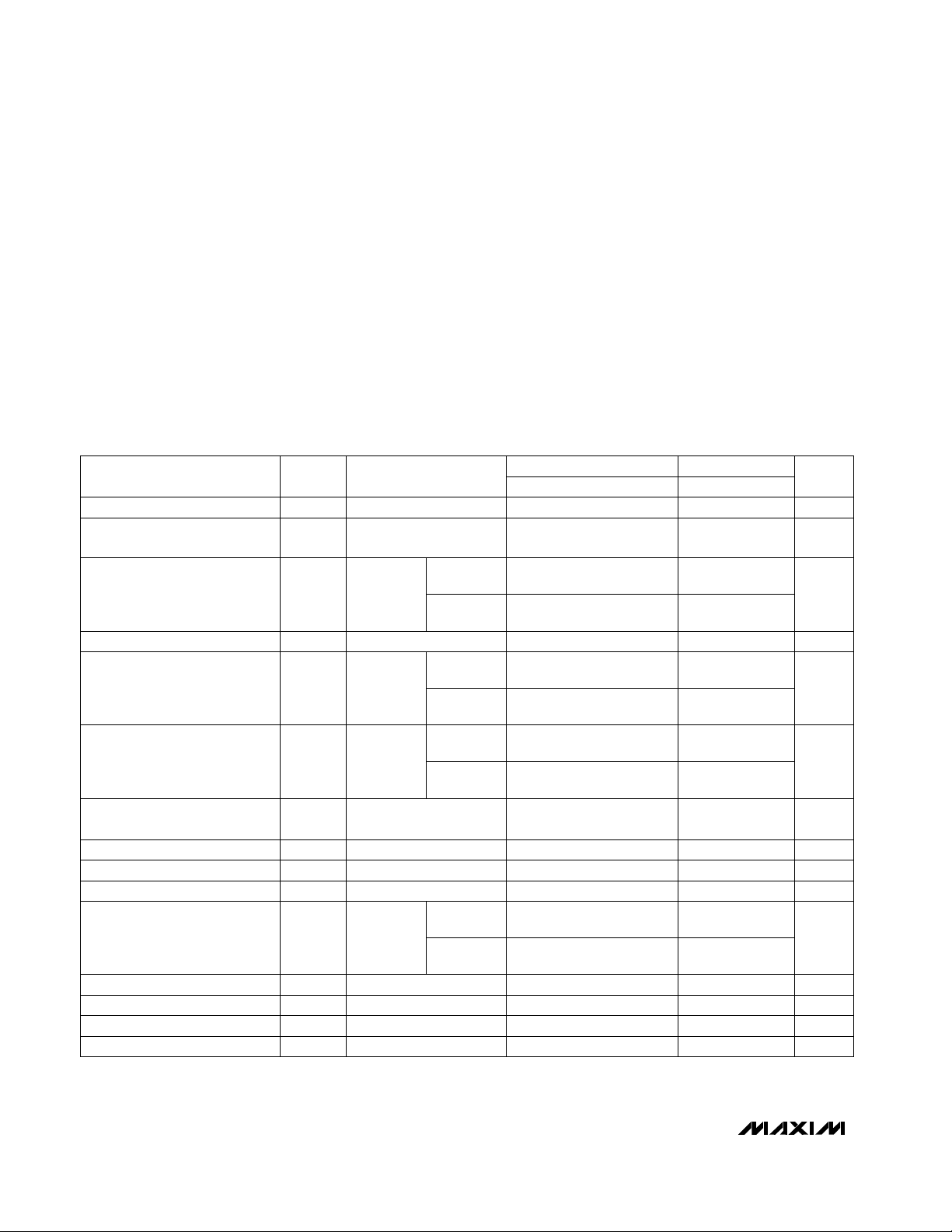
______________________Selector Guide
MAX961–MAX964/MAX997/MAX999
Single/Dual/Quad, Ultra-High-Speed, +3V/+5V,
Beyond-the-Rails Comparators
________________________________________________________________ Maxim Integrated Products 1
19-1129; Rev 4; 3/99
PART
MAX961ESA
MAX961EUA
MAX962ESA
-40°C to +85°C
-40°C to +85°C
-40°C to +85°C
TEMP RANGE
PIN-
PACKAGE
8 SO
8 µMAX
8 SO
_______________Ordering Information
MAX962EUA -40°C to +85°C 8 µMAX
PART
NO. OF
COMPARATORS
COMPLEMENTARY
OUTPUT
SHUTDOWN
LATCH
ENABLE
PACKAGE
MAX961 1 Yes Yes Yes 8 SO/µMAX
MAX962 2 No No No 8 SO/µMAX
MAX963 2 Yes Yes Yes 14 SO
MAX964 4 No Yes No 16 SO/QSOP
MAX963ESD
-40°C to +85°C 14 SO
MAX964ESE
-40°C to +85°C 16 Narrow SO
MAX964EEE -40°C to +85°C 16 QSOP
__________________Pin Configurations
Beyond-the-Rails is a trademark of Maxim Integrated Products, Inc.
GND
IN-IN+
15V
CC
Q
MAX999
SOT23-5
2
34
Pin Configurations continued at end of data sheet.
MAX997 1 No Yes No 8 SO/µMAX
MAX999 1 No No No 5 SOT23
MAX997ESA
-40°C to +85°C 8 SO
MAX997EUA -40°C to +85°C 8 µMAX
MAX999EUK-T
-40°C to +85°C 5 SOT23-5
TOP VIEW
SOT
TOP MARK
—
—
—
—
—
—
—
—
—
ACAB
Page 2
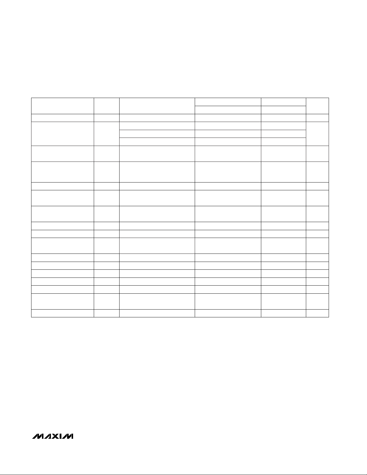
ELECTRICAL CHARACTERISTICS
(VCC= +2.7V to +5.5V, VCM= 0V, C
OUT
= 5pF, V
SHDN
= 0V, VLE= 0V, unless otherwise noted.) (Note 1)
MAX961–MAX964/MAX997/MAX999
Single/Dual/Quad, Ultra-High-Speed, +3V/+5V,
Beyond-the-Rails Comparators
2 _______________________________________________________________________________________
ABSOLUTE MAXIMUM RATINGS
Stresses beyond those listed under “Absolute Maximum Ratings” may cause permanent damage to the device. These are stress ratings only, and functional
operation of the device at these or any other conditions beyond those indicated in the operational sections of the specifications is not implied. Exposure to
absolute maximum rating conditions for extended periods may affect device reliability.
Supply Voltage, VCCto GND................................... -0.3V to +6V
All Other Pins..............................................-0.3V to (V
CC
+ 0.3V)
Duration of Output Short Circuit to GND or V
CC
.......Continuous
Continuous Power Dissipation (T
A
= +70°C)
5-Pin SOT23 (derate 7.1mW/°C above +70°C).......571mW/°C
8-Pin SO (derate 5.88mW/°C above +70°C)...........471mW/°C
8-Pin µMAX (derate 4.10mW/°C above +70°C) ......330mW/°C
14-Pin SO (derate 8.33mW/°C above +70°C).........667mW/°C
16-Pin SO (derate 8.70mW/°C above +70°C).........696mW/°C
16-Pin QSOP (derate 8.33mW/°C above +70°C)....667mW/°C
Operating Temperature Range
MAX96_E/MAX99_E.........................................-40°C to +85°C
Storage Temperature Range ............................ -65°C to +160°C
Lead Temperature (soldering, 10sec) .............................+300°C
V
OUT
= 1.4V, VCC= 2.7V
I
SINK
= 4mA
I
SOURCE
= 4mA
VCM= 0V (Note 6)
(Note 2)
Inferred by PSRR
V
CC
= 5V
V
CC
= 5V
VCM= - 0.1V
or 5.1V,
VCC= 5V
(Note 3)
mA30 60Capacitive Slew Current
V0.52V
OL
Output Low Voltage
VVCC- 0.52V
OH
Output High Voltage
mV/V0.05 0.3PSRRPower-Supply Rejection Ratio
kΩ130R
INCM
Common-Mode Input Impedance
kΩ8R
IND
Differential Input Impedance
pF3Input Capacitance
V-0.1 VCC+ 0.1V
CMR
V2.7 5.5V
CC
Supply Voltage
Input Common-Mode Voltage
Range
mV
±2.0 ±3.5
V
TRIP
Input-Referred Trip Points
±2.0 ±3.5
TA= +25°C
0.52
VCC- 0.52
0.3
-0.1 VCC+ 0.1
2.7 5.5
±4.0
±6.5
T
MIN
to T
MAX
CONDITIONS UNITS
MIN TYP MAX
SYMBOLPARAMETER
MIN MAX
µMAX,
SOT23
All other
packages
µMAX,
SOT23
VCM= - 0.1V
or 5.1V,
VCC= 5V
(Note 4)
All other
packages
mV
±0.5 ±1.5
V
OS
Input Offset Voltage
±0.5 ±1.5
±2.0
±4.5
V
CC
= 5V,
V
CM
= -0.1V
to 5.1V
(Note 5)
mV/V
0.1 0.3
CMRRCommon-Mode Rejection Ratio
1.0
µMAX,
SOT23
V
IN+
=
V
IN-
= 0V
or V
CC,
VCC= 5V
All other
packages
µA
±15
I
B
Input Bias Current
±15
±15
±30
mVInput-Referred Hysteresis 3.5
VCC= 5.5V, V
IN-
= 0V,
IIN+ = 100µA
V2.1Differential Input Clamp Voltage
µMAX,
SOT23
All other
packages
0.1 0.3 0.5
Page 3
MAX961–MAX964/MAX997/MAX999
Single/Dual/Quad, Ultra-High-Speed, +3V/+5V,
Beyond-the-Rails Comparators
_______________________________________________________________________________________ 3
ELECTRICAL CHARACTERISTICS (continued)
(VCC= +2.7V to +5.5V, VCM= 0V, C
OUT
= 5pF, V
SHDN
= 0V, VLE= 0V, unless otherwise noted.) (Note 1)
Note 1: The MAX961EUA/MAX962EUA/MAX997EUA/MAX999EUK are 100% production tested at T
A
= +25°C; all temperature specifica-
tions are guaranteed by design.
Note 2: Inferred by CMRR. Either input can be driven to the absolute maximum limit without false output inversion, provided that the other
input is within the input voltage range.
Note 3: The input-referred trip points are the extremities of the differential input voltage required to make the comparator output change
state. The difference between the upper and lower trip points is equal to the width of the input-referred hysteresis zone. (See
Figure 1.)
Note 4: Input offset voltage is defined as the mean of the trip points.
Note 5: CMRR = (V
OSL
- V
OSH
) / 5.2V, where V
OSL
is the offset at VCM= -0.1V and V
OSH
is the offset at VCM= 5.1V.
Note 6: PSRR = (V
OS
2.7 - VOS5.5) / 2.8V, where VOS2.7 is the offset voltage at VCC= 2.7V, and VOS5.5 is the offset voltage at
V
CC
= 5.5V.
Note 7: Propagation delay for these high-speed comparators is guaranteed by design characterization because it cannot be accurately
measured using automatic test equipment. A statistically significant sample of devices is characterized with a 200mV step and
100mV overdrive over the full temperature range. Propagation delay can be guaranteed by this characterization, since DC tests
ensure that all internal bias conditions are correct. For low overdrive conditions, V
TRIP
is added to the overdrive.
Note 8: Guaranteed by design.
MAX961/MAX963/MAX964/
MAX997, V
OUT
= 0.5V and
V
CC
- 0.5V
Delay until output is valid
Delay until output is high-Z
(>10kΩ)
MAX961/MAX963 (Note 8)
MAX961/MAX963 (Note 8)
5mV overdrive (Note 7)
MAX961/MAX963 (Note 8)
MAX961/MAX963 (Note 8)
V
LOGIC
= 0V or V
CC
VCC= 5V
Between t
PD-
and t
PD+
ns250t
ON
Shutdown Disable Time
ns150t
OFF
Shutdown Time
ns10t
LPD
Latch Propagation Delay
ns5t
LPW
Latch Pulse Width
ns5t
H
Latch-to-Data Hold Time
ns5t
SU
Data-to-Latch Setup Time
ns0.3t
SKEW
Propagation-Delay Skew
ns0.3t
PD
Differential Propagation
Delay
µA1
Shutdown Output
Leakage Current
pF4Output Capacitance
ns4.5 7t
PD
Propagation Delay
µA±15IIL, I
IH
Logic Input Current
V
(VCC/ 2)
- 0.4
V
IL
Logic Input Low
ns2.3tR, t
F
Rise/Fall Time
V
(V
CC
/ 2)
+ 0.4
V
IH
Logic Input High
TA= +25°C
10
5
5
5
20
8.5
±30
(VCC/ 2)
- 0.4
(VCC/ 2)
+ 0.4
T
MIN
to T
MAX
CONDITIONS UNITS
MIN TYP MAX
SYMBOLPARAMETER
MIN MAX
Between any two channels or
outputs (Q/
Q)
MAX962/MAX964, VCC= 5V 58 9
MAX961/MAX963/MAX964/
MAX997, VCC= 5V
mA0.27 0.5I
SHDN
Shutdown Supply Current
per Comparator
0.5
MAX997/MAX999, VCC= 5V 5 6.5 6.5
MAX961/MAX963, VCC= 5V 7.2 11
Supply Current
per Comparator
I
CC
11
mA
Page 4
MAX961–MAX964/MAX997/MAX999
Single/Dual/Quad, Ultra-High-Speed, +3V/+5V,
Beyond-the-Rails Comparators
4 _______________________________________________________________________________________
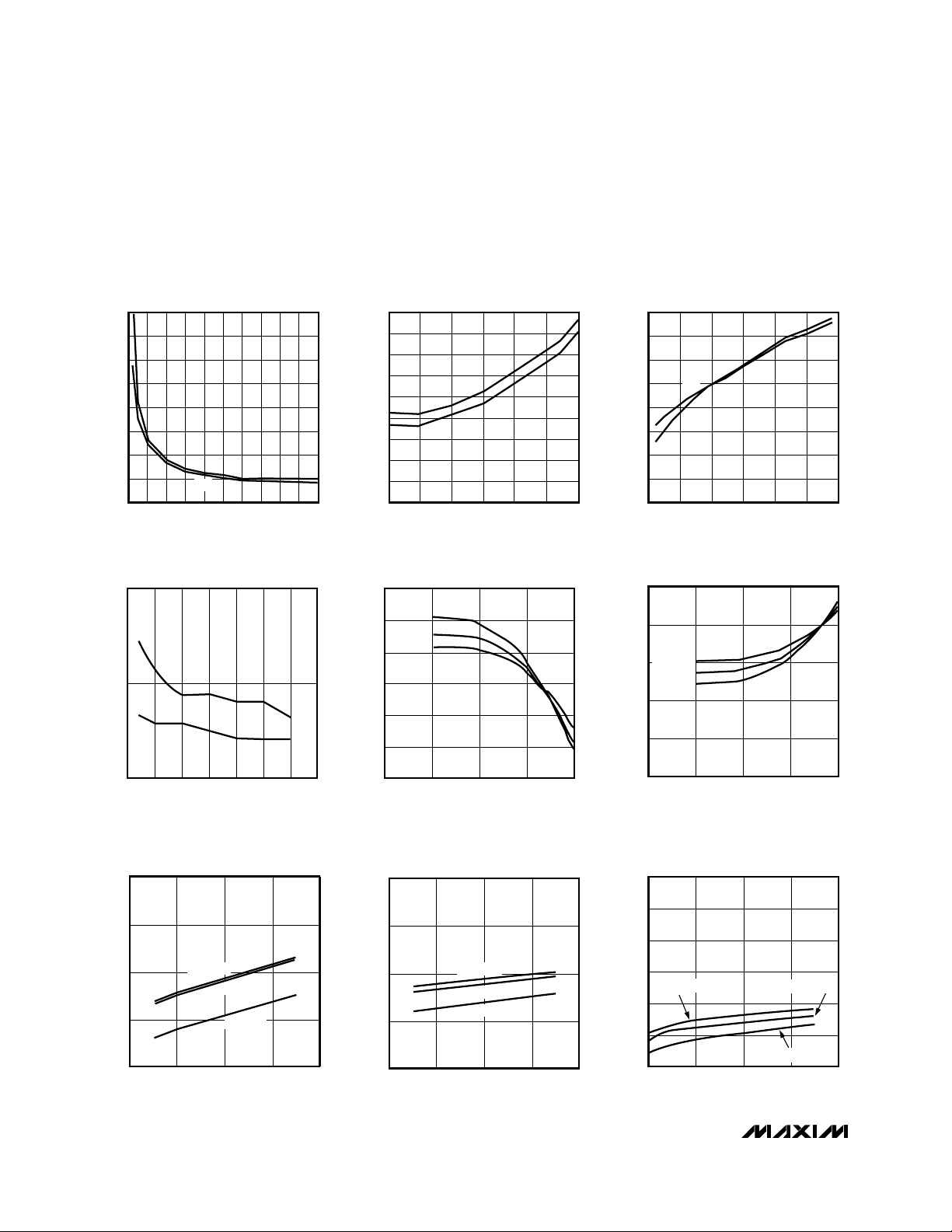
__________________________________________Typical Operating Characteristics
(VCC= +3.0V, C
LOAD
= 5pF, 5mV of overdrive, TA= +25°C, unless otherwise noted.)
0102030405060708090100
INPUT OVERDRIVE (mV)
MAX997toc01
PROPAGATION DELAY
vs. INPUT OVERDRIVE
PROPAGATION DELAY (ns)
3.5
4.0
4.5
5.0
5.5
6.0
6.5
7.5
7.0
t
PD-
t
PD+
5.0
-40 85
TEMPERATURE (°C)
PROPAGATION DELAY (ns)
20
5.2
5.4
5.6
5.8
6.0
6.2
6.4
6.6
6.8
-20 0 60
40
MAX997toc0202
PROPAGATION DELAY
vs. TEMPERATURE
tPD+
t
PD
-
0120
CAPACITIVE LOAD (pF)
6020 40 10080
MAX997toc03
PROPAGATION DELAY
vs. CAPACITIVE LOAD
PROPAGATION DELAY (ns)
8
7
6
5
4
t
PD+
t
PD-
2.5 3.5 4.5 5.5
SUPPLY VOLTAGE (V)
5.03.0 4.0 6.0
MAX997toc04
PROPAGATION DELAY
vs. SUPPLY VOLTAGE
5.0
PROPAGATION DELAY (ns)
5.5
6.0
tPD+
tPD-
26
SUPPLY VOLTAGE (V)
SUPPLY CURRENT (mA)
5
6.0
6.5
7.0
7.5
8.0
34
MAX997toc07A
MAX961/MAX963
SUPPLY CURRENT PER COMPARATOR
vs. SUPPLY VOLTAGE
TA = +85°C
TA = -40°C
TA = +25°C
1101001000 10,000
SOURCE CURRENT (µA)
MAX997toc05
OUTPUT HIGH VOLTAGE
vs. SOURCE CURRENT
V
OH
(V)
2.50
2.55
2.60
2.65
2.70
2.80
2.75
TA = -40°C
TA = +25°C
TA = +85°C
110100 1000 10,000
SINK CURRENT (µA)
MAX997toc06
OUTPUT LOW VOLTAGE
vs. SINK CURRENT
V
OL
(V)
0
0.1
0.2
0.3
0.4
0.5
TA = -40°C
TA = +85°C
TA = +25°C
3
4
5
6
7
26
SUPPLY VOLTAGE (V)
SUPPLY CURRENT (mA)
534
MAX997toc07B
MAX962/MAX964
SUPPLY CURRENT PER COMPARATOR
vs. SUPPLY VOLTAGE
TA = -40°C
TA = +85°C
TA = +25°C
3
4
5
6
7
8
9
26
SUPPLY VOLTAGE (V)
SUPPLY CURRENT (mA)
534
MAX9997toc7C
MAX997/MAX999
SUPPLY CURRENT PER COMPARATOR
vs. SUPPLY VOLTAGE
TA = -40°C
TA = +85°C
TA = +25°C
Page 5

MAX961–MAX964/MAX997/MAX999
Single/Dual/Quad, Ultra-High-Speed, +3V/+5V,
Beyond-the-Rails Comparators
_______________________________________________________________________________________ 5
60
-40 80
310
260
TEMPERATURE (°C)
SHUTDOWN SUPPLY CURRENT (µA)
20
160
110
-20 0 60
210
40
MAX997toc08
MAX961/MAX963/MAX964/MAX997
SHUTDOWN SUPPLY CURRENT
vs. TEMPERATURE
V
CC
= 5.0V
V
CC
= 2.7V
26
SUPPLY VOLTAGE (V)
534
MAX997toc10
VOLTAGE TRIP POINT/INPUT OFFSET
VOLTAGE vs. SUPPLY VOLTAGE
-3
-4
TRIP POINT / V
OS
(mV)
4
3
2
1
0
-1
-2
V
TRIP+
V
OS
V
TRIP-
-1 0 123456
V
CM
(V)
MAX997toc11
INPUT BIAS CURRENT (IB+, IB-)
vs. COMMON-MODE VOLTAGE
I
B+
, I
B-
(µA)
-6
-4
-2
0
2
4
6
8
-8
V
CC
= 5.0V
V
IN
= V
OS
NEGATIVE
VALUES
REPRESENT
CURRENT
FLOWING INTO
THE DEVICE
TA = -40°C
TA = +85°C
TA = +25°C
-0.5
-40 80
TEMPERATURE (°C)
INPUT BIAS/OFFSET CURRENT (µA)
20
0
0.5
1.0
1.5
2.0
2.5
3.0
3.5
4.0
-20 0 60
40
MAX997toc12
INPUT BIAS CURRENT/INPUT OFFSET
CURRENT vs. TEMPERATURE
I
OS
I
B+
I
B-
____________________________Typical Operating Characteristics (continued)
(VCC= +3.0V, C
LOAD
= 5pF, 5mV of overdrive, TA= +25°C, unless otherwise noted.)
0
-40 80
140
120
TEMPERATURE (°C)
SHORT-CIRCUIT CURRENT (mA)
20
60
40
20
-20 0 60
80
100
40
MAX997toc13
SHORT-CIRCUIT OUTPUT CURRENT
vs. TEMPERATURE
OUTPUT SHORTED
TO GND (SOURCING)
OUTPUT SHORTED
TO V
CC
(SINKING)
3
-3
-40 85
2
V
TRIP+
V
TRIP-
V
OS
1
TEMPERATURE (°C)
TRIP POINT / V
OS
(mV)
20
-1
-2
-20 0 60
0
40
MAX997toc09
VOLTAGE TRIP POINT/INPUT OFFSET
VOLTAGE vs. TEMPERATURE
MAX997toc14
50MHz RESPONSE
V
OS
V
IN
= 100mVp-p
GND
5ns/div
OUTPUT
1V/div
INPUT
50mV/div
Page 6

MAX961–MAX964/MAX997/MAX999
Single/Dual/Quad, Ultra-High-Speed, +3V/+5V,
Beyond-the-Rails Comparators
6 _______________________________________________________________________________________
______________________________________________________________Pin Description
Comparator D Inverting Input—
Comparator D Noninverting Input
—
Comparator B Output—
Comparator C Output—
Comparator B Noninverting Input—
Comparator C Inverting Input
—
Comparator C Noninverting Input
—
Comparator B Inverting Input—
Comparator A Noninverting Input3
—
—
6
—
3
—
—
4
1
____________________________Typical Operating Characteristics (continued)
(VCC= +3.0V, C
LOAD
= 5pF, 5mV of overdrive, TA= +25°C, unless otherwise noted.)
MAX997toc15
PROPAGATION DELAY (t
PD+
)
GND
GND
5ns/div
OUTPUT
1V/div
INPUT
50mV/div
MAX997toc16
PROPAGATION DELAY (t
PD-
)
GND
GND
5ns/div
OUTPUT
1V/div
INPUT
50mV/div
Ground
4
Latch-Enable Input. The output latches when LE_
is high. The latch is transparent when LE_ is low.
—
5
—
Shutdown Input. The device shuts down when
SHDN is high.
8
—
No Connect. Connect to GND to prevent parasitic feedback.
— —
—
—
9
4, 11
—
7
3, 5
—
—
6
2
8
—
7
8
14
12
11
4
—
5
6
3
2
9
16
IND-
IND+
QB
GND
QC
INB+
LE, LEA,
LEB
INC-
INC+
INB-
IN+, INA+
SHDN
N.C.
No Connection1, 5 — — — N.C.
Comparator D Output— 10
—
— QD
Comparator B Complementary Output— —
—
10
QB
Positive Supply Input (VCCto GND must be
≤5.5V)
7 138 12 V
CC
Comparator A TTL Output6 157 13 Q, QA
Comparator A Complementary Output— —
—
14
Q, QA
—
—
—
5
—
—
4
—
—
—
1
—
—
3
—
—
8
6
7
—
—
—
2
—
—
—
—
—
—
3
—
—
—
—
—
5
1
—
Comparator A Inverting Input2 2 1 1 IN-, INA-24
PIN
MAX963 MAX964MAX997 MAX962MAX961MAX999
NAME FUNCTION
Page 7

MAX961–MAX964/MAX997/MAX999
Single/Dual/Quad, Ultra-High-Speed, +3V/+5V,
Beyond-the-Rails Comparators
_______________________________________________________________________________________ 7
_______________Detailed Description
The MAX961–MAX964/MAX997/MAX999 single-supply
comparators feature internal hysteresis, ultra-highspeed operation, and low power consumption. Their
outputs are guaranteed to pull within 0.52V of either rail
without external pull-up or pull-down circuitry. Beyondthe-Rails™input voltage range and low-voltage, singlesupply operation make these devices ideal for portable
equipment. These comparators all interface directly to
CMOS logic.
Timing
Most high-speed comparators oscillate in the linear
region because of noise or undesirable parasitic feedback. This can occur when the voltage on one input is
close to or equal to the voltage on the other input.
These devices have a small amount of internal hysteresis to counter parasitic effects and noise.
The added hysteresis of the MAX961–MAX964/MAX997/
MAX999 creates two trip points: one for the rising input
voltage and one for the falling input voltage (Figure 1).
The difference between the trip points is the hysteresis.
When the comparator’s input voltages are equal, the
hysteresis effectively causes one comparator input
voltage to move quickly past the other, thus taking the
input out of the region where oscillation occurs. Standard
comparators require hysteresis to be added with external
resistors. The fixed internal hysteresis eliminates these
resistors.
The MAX961/MAX963 include internal latches that allow
storage of comparison results. LE has a high input
impedance. If LE is low, the latch is transparent (i.e.,
the comparator operates as though the latch is not present). The comparator’s output state is stored when LE
is pulled high. All timing constraints must be met when
using the latch function (Figure 2).
Input Stage Circuitry
The MAX961–MAX964/MAX997/MAX999 include internal protection circuitry that prevents damage to the precision input stage from large differential input voltages.
This protection circuitry consists of two groups of three
front-to-back diodes between IN+ and IN-, as well as
two 200Ω resistors (Figure 3). The diodes limit the differential voltage applied to the comparator’s internal
circuitry to no more than 3V
F
, where VFis the diode’s
forward-voltage drop (about 0.7V at +25°C).
Q
V
OL
V
OH
V
TRIP+
V
HYST
V
TRIP-
Q
V
OL
V
OH
V
TRIP+
+ V
TRIP-
2
VOS =
V
IN-
= 0V
V
IN+
Figure 1. Input and Output Waveforms, Noninverting Input Varied
Page 8

MAX961–MAX964/MAX997/MAX999
Single/Dual/Quad, Ultra-High-Speed, +3V/+5V,
Beyond-the-Rails Comparators
8 _______________________________________________________________________________________
For a large differential input voltage (exceeding 3VF),
this protection circuitry increases the input bias current
at IN+ (source) and IN- (sink).
(IN+ - IN-) - 3V
F
Input current = ————————
2 x 200
Input currents with large differential input voltages
should not be confused with input bias currents (I
B
).
As long as the differential input voltage is less than
3VF, this input current is less than 2IB.
The input circuitry allows the MAX961–MAX964/
MAX997/MAX999’s input common-mode range to
extend 100mV beyond both power-supply rails. The
output remains in the correct logic state if one or both
inputs are within the common-mode range. Taking
either input outside the common-mode range causes
the input to saturate and the propagation delay to
increase.
t
H
t
SU
t
LPW
0V
V
CC
V
OS
DIFFERENTIAL
INPUT
VOLTAGE
LE
Q
Q
V
OL
V
OH
t
LPD
t
PD
t
SKEW
t
SKEW
V
CC
2
V
CC
2
V
CC
2
Figure 2. MAX961/MAX963 Timing Diagram
MAX961-MAX964
MAX997
MAX999
IN+
200Ω
TO INTERNAL
CIRCUITRY
IN-
200Ω
TO INTERNAL
CIRCUITRY
Figure 3. Input Stage Circuitry
Page 9

MAX961–MAX964/MAX997/MAX999
Single/Dual/Quad, Ultra-High-Speed, +3V/+5V,
Beyond-the-Rails Comparators
_______________________________________________________________________________________ 9
Output Stage Circuitry
The MAX961–MAX964/MAX997/MAX999 contain a current-driven output stage, as shown in Figure 4. During an
output transition, I
SOURCE
or I
SINK
is pushed or pulled to
the output pin. The output source or sink current is high
during the transition, creating a rapid slew rate. Once the
output voltage reaches V
OH
or VOL, the source or sink
current decreases to a small value, capable of maintaining the VOHor VOLin static condition. This decrease in
current conserves power after an output transition has
occurred.
One consequence of a current-driven output stage is a
linear dependence between the slew rate and the load
capacitance. A heavy capacitive load slows down the
voltage output transition.
Shutdown Mode
When SHDN is high, the MAX961/MAX963/MAX964/
MAX997 shut down. When shut down, the supply current drops to 270µA per comparator, and the outputs
become high impedance. SHDN has a high input
impedance. Connect SHDN to GND for normal operation. Exit shutdown with LE low; otherwise, the output is
indeterminate.
__________Applications Information
Circuit Layout and Bypassing
The MAX961–MAX964/MAX997/MAX999’s high bandwidth requires a high-speed layout. Follow these layout
guidelines:
1) Use a printed circuit board with a good, unbroken,
low-inductance ground plane.
2) Place a decoupling capacitor (a 0.1µF ceramic surface-mount capacitor is a good choice) as close to
V
CC
as possible.
3) On the inputs and outputs, keep lead lengths short
to avoid unwanted parasitic feedback around the
comparators. Keep inputs away from outputs. Keep
impedance between the inputs low.
4) Solder the device directly to the printed circuit board
rather than using a socket.
5) Refer to Figure 5 for a recommended circuit layout.
6) For slow-moving input signals, take care to prevent
parasitic feedback. A small capacitor (1000pF or
less) placed between the inputs can help eliminate
oscillations in the transition region. This capacitor
causes negligible degradation to t
PD
when the
source impedance is low.
Figure 4. Output Stage Circuitry
MAX961-MAX964
MAX997
MAX999
I
SOURCE
Q, Q
V
CC
GND
I
SINK
Figure 5. MAX961 PC Board Layout
Page 10

Single/Dual/Quad, Ultra-High-Speed, +3V/+5V,
Beyond-the-Rails Comparators
10 ______________________________________________________________________________________
SO/µMAX
QB
INB+
GND
INB-
1
2
8
7
V
CC
QA
INA-
INA+
MAX962
3
4
6
5
SO/µMAX
Q
IN+
N.C.
GND
1
2
8
7
V
CC
SHDN
IN-
N.C.
MAX997
3
4
6
5
SO
SO/QSOP
16
15
14
13
12
11
10
9
1
2
3
4
5
6
7
8
INA- N.C.
QA
QB
V
CC
GND
QC
QD
SHDN
MAX964
INA+
INB-
INC+
INB+
INC-
IND-
IND+
14
13
12
11
10
9
8
1
2
3
4
5
6
7
QA
QA
V
CC
GNDGND
LEA
INA+
INA-
MAX963
QB
QB
SHDNINB+
INB-
LEB
Q
SHDN
GND
LE
1
2
8
7
V
CC
Q
IN-
IN+
MAX961
SO/µMAX
3
4
6
5
___________________________________________________________Pin Configurations
TOP VIEW
___________________Chip Information
MAX961/MAX962 TRANSISTOR COUNT: 286
MAX963/MAX964 TRANSISTOR COUNT: 607
MAX997/MAX999 TRANSISTOR COUNT: 142
MAX961–MAX964/MAX997/MAX999
Page 11

MAX961–MAX964/MAX997/MAX999
Single/Dual/Quad, Ultra-High-Speed, +3V/+5V,
Beyond-the-Rails Comparators
______________________________________________________________________________________ 11
8LUMAXD.EPS
PACKAGE OUTLINE, 8L uMAX/uSOP
1
1
21-0036
J
REV.DOCUMENT CONTROL NO.APPROVAL
PROPRIETARY INFORMATION
TITLE:
MAX
0.043
0.006
0.014
0.120
0.120
0.198
0.026
0.007
0.037
0.0207 BSC
0.0256 BSC
A2
A1
c
e
b
A
L
FRONT VIEW
SIDE VIEW
E H
0.6±0.1
0.6±0.1
ÿ 0.50±0.1
1
TOP VIEW
D
8
A2
0.030
BOTTOM VIEW
1
6∞
S
b
L
H
E
D
e
c
0∞
0.010
0.116
0.116
0.188
0.016
0.005
8
4X S
INCHES
-
A1
A
MIN
0.002
0.950.75
0.5250 BSC
0.25 0.36
2.95 3.05
2.95 3.05
4.78
0.41
0.65 BSC
5.03
0.66
6∞0∞
0.13 0.18
MAX
MIN
MILLIMETERS
- 1.10
0.05 0.15
α
α
DIM
QSOP.EPS
Package Information
(The package drawing(s) in this data sheet may not reflect the most current specifications. For the latest package outline information
go to www.maxim-ic.com/packages
.)
Page 12

MAX961–MAX964/MAX997/MAX999
Single/Dual/Quad, Ultra-High-Speed, +3V/+5V,
Beyond-the-Rails Comparators
Maxim cannot assume responsibility for use of any circuitry other than circuitry entirely embodied in a Maxim product. No circuit patent licenses are
implied. Maxim reserves the right to change the circuitry and specifications without notice at any time.
12 ____________________Maxim Integrated Products, 120 San Gabriel Drive, Sunnyvale, CA 94086 408-737-7600
© 1999 Maxim Integrated Products Printed USA is a registered trademark of Maxim Integrated Products.
SOICN .EPS
PACKAGE OUTLINE, .150" SOIC
1
1
21-0041
B
REV.DOCUMENT CONTROL NO.APPROVAL
PROPRIETARY INFORMATION
TITLE:
TOP VIEW
FRONT VIEW
MAX
0.010
0.069
0.019
0.157
0.010
INCHES
0.150
0.007
E
C
DIM
0.014
0.004
B
A1
MIN
0.053A
0.19
3.80 4.00
0.25
MILLIMETERS
0.10
0.35
1.35
MIN
0.49
0.25
MAX
1.75
0.050
0.016L
0.40 1.27
0.3940.386D
D
MINDIM
D
INCHES
MAX
9.80 10.00
MILLIMETERS
MIN
MAX
16
AC
0.337 0.344 AB8.758.55 14
0.189 0.197 AA5.004.80 8
N MS012
N
SIDE VIEW
H 0.2440.228 5.80 6.20
e 0.050 BSC 1.27 BSC
C
HE
e
B
A1
A
D
0∞-8∞
L
1
VARIATIONS:
SOT-23 5L .EPS
E
1
1
21-0057
PACKAGE OUTLINE, SOT-23, 5L
Package Information (continued)
(The package drawing(s) in this data sheet may not reflect the most current specifications. For the latest package outline information
go to www.maxim-ic.com/packages
.)
 Loading...