

General Description
The MAX9600/MAX9601/MAX9602 ultra-high-speed comparators feature extremely low propagation delay
(500ps). These dual and quad comparators minimize
propagation delay skew (10ps) and are designed for low
propagation delay dispersion (30ps). These features
make them ideal for applications where high-fidelity tracking of narrow pulses and low timing dispersion is critical.
The differential input stage accepts a wide range of signals
in the common-mode range from (VEE+ 3V) to (VCC- 2V).
The outputs are complementary digital signals, compatible
with ECL and PECL systems, and provide sufficient current
to directly drive transmission lines terminated in 50Ω.
The MAX9600/MAX9601 dual-channel ECL and dual-channel PECL output comparators incorporate latch enable
(LE_, LE_), and hysteresis (HYS_). The complementary
latch-enable control permits tracking, track-hold, or samplehold mode of operations. The latch enables can be driven
with standard ECL logic for MAX9600 and PECL logic for
MAX9601. The MAX9602 quad-channel PECL output
comparator is ideal for high-density packaging in limited board space.
The MAX9600/MAX9601 are available in 20-pin TSSOP
packages, and the MAX9602 is offered in a 24-pin
TSSOP package. The MAX9600/MAX9601/MAX9602
are specified for operation from -40°C to +85°C.
Applications
VLSI and High-Speed Memory ATE
High-Speed Instrumentation
Scope/Logic Analyzer Front Ends
High-Speed Triggering
Threshold and Peak Detection
Line Receiving/Signal Restoration
Features
♦ 500ps Propagation Delay
♦ 30ps Propagation Delay Dispersion
♦ 4Gbps Tracking Frequency
♦ -2.2V to +3V Input Range with +5V/-5.2V Supplies
♦ -1.2V to +4V Input Range with +6V/-4.2V Supplies
♦ Differential ECL Outputs (MAX9600)
♦ Differential PECL Outputs (MAX9601/MAX9602)
♦ Latch Enable (MAX9600/MAX9601)
♦ Adjustable Hysteresis (MAX9600/MAX9601)
MAX9600/MAX9601/MAX9602
Dual ECL and Dual/Quad PECL, 500ps,
Ultra-High-Speed Comparators
________________________________________________________________ Maxim Integrated Products 1
Ordering Information
19-2409; Rev 1; 9/02
For pricing, delivery, and ordering information, please contact Maxim/Dallas Direct! at
1-888-629-4642, or visit Maxim’s website at www.maxim-ic.com.
Pin Configurations appear at end of data sheet.
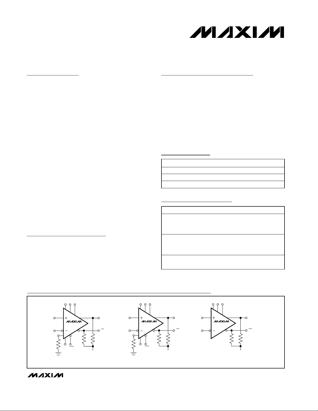
Functional Diagrams
Selector Guide
PART TEMP RANGE PIN-PACKAGE
MAX9600EUP -40°C to +85°C 20 TSSOP
MAX9601EUP -40°C to +85°C 20 TSSOP
MAX9602EUG -40°C to +85°C 24 TSSOP
PART PIN-PACKAGE SELECTION
MAX9600EUP 20 TSSOP
Dual ECL Output
Comparator with Latch
Enable and Hysteresis
VCCVEEGND
IN_+ Q_
R
LRL
V
= -2V
T
ECL OUTPUT
Q_
IN_-
HYS_
R
HYS_
1/2 MAX9600
LE_
LE_
THE OPEN-EMITTER OUTPUTS REQUIRE EXTERNAL PULLDOWN RESISTORS (RL). USE RESISTORS IN THE RANGE OF 50Ω TO 75Ω CONNECTED TO VT.
CURRENT-CONTROLLED HYSTERESIS REQUIRES A SINGLE EXTERNAL RESISTOR (R
MAX9601EUP 20 TSSOP
MAX9602EUG 24 TSSOP
VCCVEEV
CCO_
IN_+ Q_
PECL OUTPUT
R
LRL
= V
V
T
CCO_
) FROM HYS_ TO GND IN THE RANGE OF 10kΩ TO 35kΩ.
HYS_
IN_-
HYS_
R
HYS_
1/2 MAX9601
LE_
LE_
Dual PECL Output
Comparator with Latch
Enable and Hysteresis
Quad PECL Output
Comparator
V
CCVEEVCCO_
IN_+ Q_
R
LRL
= V
V
T
PECL OUTPUT
Q_
- 2V
CCO_
Q_
IN_-
- 2V
1/4 MAX9602
MAX9600/MAX9601/MAX9602
Dual ECL and Dual/Quad PECL, 500ps,
Ultra-High-Speed Comparators
2 _______________________________________________________________________________________
ABSOLUTE MAXIMUM RATINGS
Stresses beyond those listed under “Absolute Maximum Ratings” may cause permanent damage to the device. These are stress ratings only, and functional
operation of the device at these or any other conditions beyond those indicated in the operational sections of the specifications is not implied. Exposure to
absolute maximum rating conditions for extended periods may affect device reliability.
VS= VCC- VEE...................................................................12.0V
V
CC
to GND (MAX9600) .......................................................6.8V
V
EE
to GND (MAX9600) ......................................................-6.5V
Differential Input Voltage ...................................................±6.5V
Latch Differential Voltage ......................................................±4V
Common-Mode Input Voltage (V
CM
) .........................VEEto V
CC
V
CCO
_ to V
EE
(MAX9601/MAX9602)....................(VEE- 0.3V) to (VCC+ 0.3V)
LE_, LE_ to GND
MAX9600 ....................................................(V
EE
- 0.3V) to 0.3V
MAX9601 ..................................(V
EE
- 0.3V) to (V
CCO
_ + 0.3V)
Input Current to Any Input Pin.............................................10mA
HYS_ Current (MAX9600/MAX9601) ...................................-1mA
Continuous Output Current .................................................50mA
Continuous Power Dissipation (T
A
= +70°C)
20-Pin TSSOP (derate 10.9mW/
o
C above +70°C) ........879mW
24-Pin TSSOP (derate 12.2mW/°C above +70°C) ........975mW
Operating Temperature Range ...........................-40°C to +85°C
Junction Temperature......................................................+150°C
Storage Temperature Range .............................-65°C to +150°C
Lead Temperature (soldering, 10s) .................................+300°C
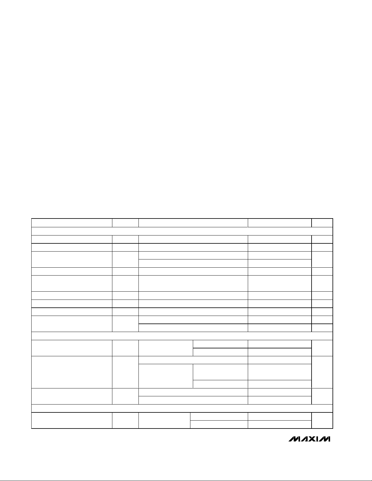
DC ELECTRICAL CHARACTERISTICS
(VCC= 5V, VEE= -5.2V, VCM= 0V, HYS_ = open (MAX9600/MAX9601), LE_ = low, LE_ = high (MAX9600/MAX9601), GND = 0V,
R
L
= 50Ω to -2V (MAX9600), V
CCO
_ = 5V, RL= 50Ω to 3V (MAX9601/MAX9602), TA= T
MIN
to T
MAX
. Typical values are at
T
A
= +25°C, unless otherwise noted.) (Note 1)
PARAMETER SYMBOL CONDITIONS MIN TYP MAX UNITS
INPUT (IN_+, IN_-)
Input Differential Voltage Range V
Input Common-Mode Voltage V
Input Offset Voltage V
Input Offset-Voltage Tempco TCV
Input Offset-Voltage Channel
Matching
Input Bias Current I
Input Bias-Current Tempco TCI
Input Offset Current I
Input Resistance R
LATCH INPUT (LE_, LE_)
Latch Differential Input Voltage V
Latch Input Current ILE, I
HYSTERESIS INPUT (HYS_)
Input-Referred Hysteresis MAX9600/MAX9601
Guaranteed by input bias current tests -5.2 +5.2 V
ID
Guaranteed by input bias current tests VEE + 3 V
CM
TA = +25°C ±1 ±5
OS
T
≤ TA ≤ T
MIN
OS
VID = ±5.2V 6 20 µA
B
B
OS
Differential mode (VID ≤ 10mV) 10 kΩ
IN
Common mode (VEE + 3V) ≤ VCM ≤ (V
Guaranteed by latch
LD
input current
MAX
MAX9600 -2 0
LR
MAX9601
MAX9600 5 20
LE
MAX9601 5 20
- 2 V
CC
±9
8 µV/°C
1mV
10 nA/°C
0.3 ±5µA
- 2V) 100 MΩ
CC
MAX9600 0.4 2.0
MAX9601 0.25 3.50
V
_
V
≥ 3.5V
CCO_
_ < 3.5V 0 V
V
CCO
R
= ∞ 0
HYS
R
= 16.4kΩ 30
HYS
CCO
- 3.5
V
CCO
CCO
_Latch Input Voltage Range V
_
mV
V
V
µA
mV
MAX9600/MAX9601/MAX9602
Dual ECL and Dual/Quad PECL, 500ps,
Ultra-High-Speed Comparators
_______________________________________________________________________________________ 3
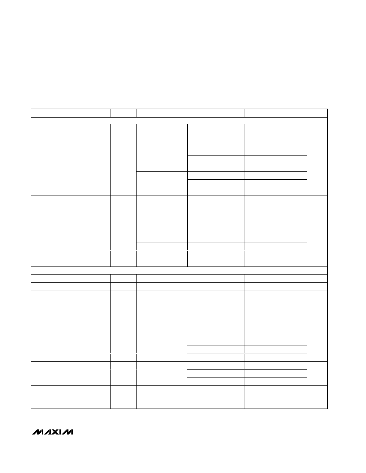
DC ELECTRICAL CHARACTERISTICS (continued)
(VCC= 5V, VEE= -5.2V, VCM= 0V, HYS_ = open (MAX9600/MAX9601), LE_ = low, LE_ = high (MAX9600/MAX9601), GND = 0V,
R
L
= 50Ω to -2V (MAX9600), V
CCO
_ = 5V, RL= 50Ω to 3V (MAX9601/MAX9602), TA= T
MIN
to T
MAX
. Typical values are at
T
A
= +25°C, unless otherwise noted.) (Note 1)
PARAMETER SYMBOL CONDITIONS MIN TYP MAX UNITS
OUTPUT (Q_, Q____)
Logic Output High Voltage V
Logic Output Low Voltage V
SUPPLY
Positive Supply Voltage V
Negative Supply Voltage V
Supply Voltage Difference V
Logic Supply Voltage V
Positive Supply Current I
Negative Supply Current I
Common-Mode Rejection Ratio CMRR (VEE + 3V) ≤ VCM ≤ (V
Power-Supply Rejection Ratio PSRR
MAX9600 -1.10 -0.94 -0.75
TA = +25°C
MAX9601/MAX9602
MAX9600 -1.2 -1.02 -0.8
TA = T
OH
MIN
MAX9601/MAX9602
MAX9600 -1.05 -0.87 -0.70
TA = T
MAX
MAX9601/MAX9602
MAX9600 -1.95 -1.72 -1.55
TA = +25°C
MAX9601/MAX9602
MAX9600 -2.0 -1.78 -1.6
TA = T
OL
MIN
MAX9601/MAX9602
MAX9600 -1.9 -1.66 -1.50
TA = T
MAX
Guaranteed by output swing tests 4.3 5 6.3 V
CC
Guaranteed by output swing tests -6 -5.2 -4 V
EE
VS = (VCC - VEE), guaranteed by
S
output swing tests
_ MAX9601/MAX9602 2.4 V
CCO
MAX9601/MAX9602
MAX9600 16 24
CC
(Note 2)
MAX9601 19 27
MAX9602 28 39
MAX9600 21 28
EE
(Note 2)
MAX9601 24 33
MAX9602 38 49
MAX9600 190 266
DISS
(Note 2)
MAX9601 220 307Power-Supply Dissipation P
MAX9602 338 450
- 2V) 70 dB
CC
4.3V ≤ V
9.5V ≤ V
≤ 6.3V, -6V ≤ VEE ≤ -4V,
CC
≤ 11.5V
S
V
- 1.10
V
V
- 1.05
V
- 1.95
V
V
CCO
CCO
- 1.2
CCO
CCO
CCO
- 2.0
CCO
- 1.9
_
V
_
V
CCO
- 0.94
_
V
CCO
- 1.02
_
V
CCO
- 0.87
_
V
CCO
- 1.72
_
V
CCO
- 1.78
_
V
CCO
- 1.66
CCO
- 0.75
_
V
CCO
- 0.8
_
V
CCO
- 0.70
_
V
CCO
- 1.55
_
V
CCO
- 1.6
_
V
CCO
- 1.5
9.5 11.5 V
CC
65 dB
_
V
_
_
_
V
_
_
V
mA
mA
mW
MAX9600/MAX9601/MAX9602
Dual ECL and Dual/Quad PECL, 500ps,
Ultra-High-Speed Comparators
4 _______________________________________________________________________________________
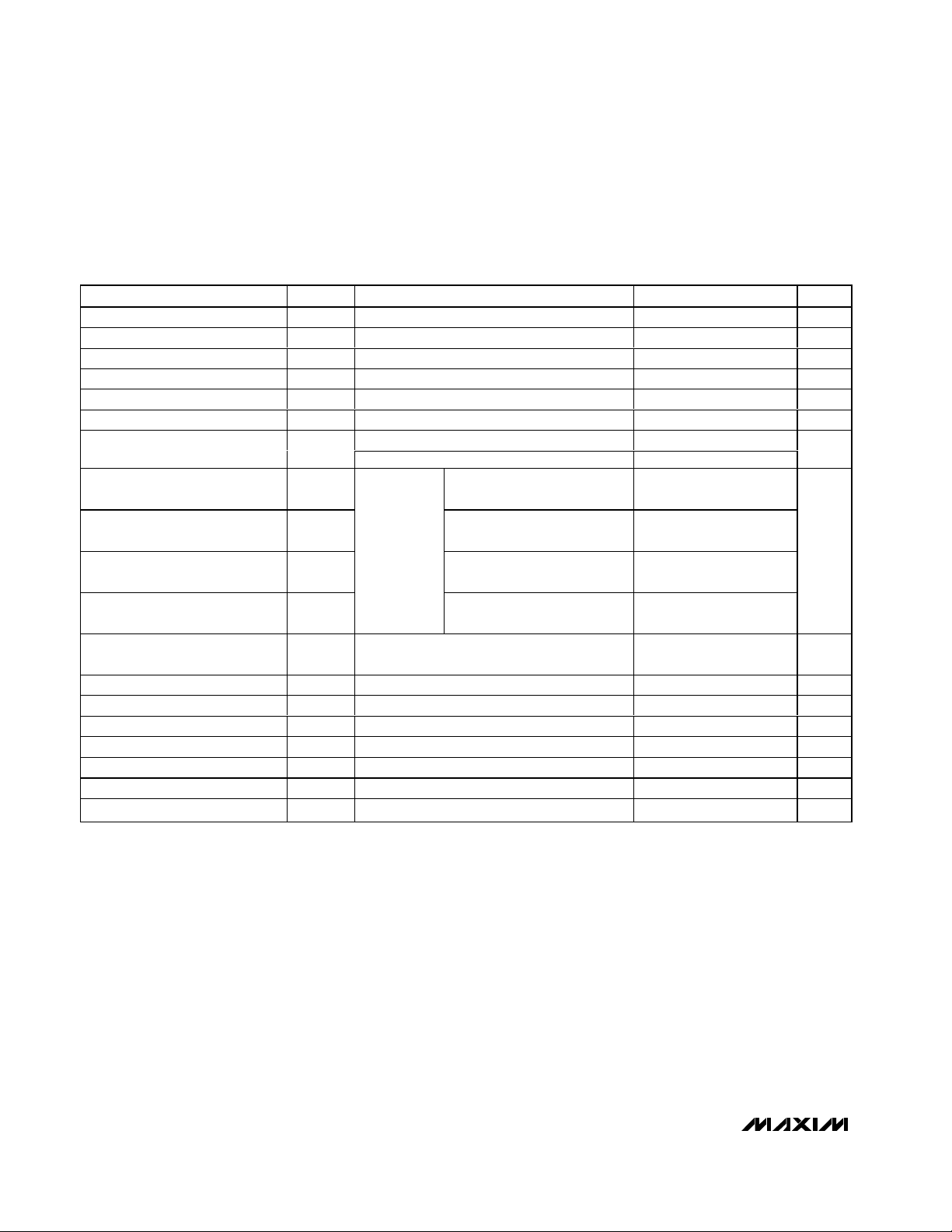
AC ELECTRICAL CHARACTERISTICS
(VCC= 5V, VEE= -5.2V, VCM= 0V, HYS_ = open (MAX9600/MAX9601), LE_ = low, LE_ = high (MAX9600/MAX9601), CL= 5pF,
GND = 0V, R
L
= 50Ω to -2V (MAX9600), V
CCO
_ = 5V, RL= 50Ω to 3V (MAX9601/MAX9602), TA= T
MIN
to T
MAX
. Typical values are at
T
A
= +25°C, unless otherwise noted.) (Note 1)
Note 1: All devices are 100% production tested at TA= +25°C. Specifications over temperature are guaranteed by design.
Note 2: Does not include output state current in Q_, Q_.
Note 3: Guaranteed by design.
Note 4: Propagation delay skew (t
PDSKEW
) is for a single channel and is the difference between the propagation delay to the high-
to-low output transition vs. the low-to-high output transition.
Note 5: Propagation delay match is the difference of t
PD-
or t
PD+
of one channel to the t
PD-
or t
PD+
of another channel of the same device.
Note 6: Latch setup and hold-timing specifications are for a differentially driven latch signal.
Tracking Frequency Toggle Rate f
Minimum Pulse Width t
Propagation Delay t
Propagation Delay Tempco TCt
Propagation Delay Skew t
Propagation Delay Match Input overdrive = 100mV (Note 5) 40 ps
Propagation Delay Dispersion
Overdrive
Propagation Delay Dispersion
Common-Mode Voltage
Propagation Delay Dispersion
Input Slew Rate
Propagation Delay Dispersion
Duty Cycle
Propagation Delay Dispersion
Pulse Width
Unit-to-Unit Propagation Delay
Match
Output Jitter V
Input Capacitance C
Latch Setup Time t
Latch Hold Time t
Minimum Pulse Width t
Latch to Output Delay t
Rise Time and Fall Time t
PARAMETER SYMBOL CONDITIONS MIN TYP MAX UNITS
PD-, tPD+
PDSKEW
V
MAX
PW
IN
LS
LH
LPW
LPD
R, tF
= 550mV
OUT
V
= 550mV
OUT
Input overdrive = 100mV, Figure 1, (Note 3) 500 700 ps
PD
Input overdrive = 100mV (Note 4) 10 ps
10mV to 100mV 15
100mV to 2V 40
= 1V
V
IN
IN
= 2V
P-P
P-P
input
overdrive =
100mV
Input overdrive = 100mV 50 ps
IN_+ or IN_, with respect to GND 2 pF
Figure 1, (Notes 3, 6) 250 80 ps
Figure 1, (Notes 3, 6) 300 85 ps
Figure 1 250 ps
Figure 1 200 ps
20% to 80%, Figure 1 200 ps
, input overdrive = 100mV 4 Gbps
P-P
input overdrive = 100mV 250 ps
P-P,
+ 3V) ≤ VCM ≤ (VCC - 2V) 10
(V
EE
0.2V/ns to 10V/ns 40
10% to 90% at 250MHz 30
350ps to 1ns 20
; 50MHz 300 fs
0.5 ps/°C
ps
ps

MAX9600/MAX9601/MAX9602
Dual ECL and Dual/Quad PECL, 500ps,
Ultra-High-Speed Comparators
_______________________________________________________________________________________ 5
Typical Operating Characteristics
(VCC= 5V, VEE= -5.2V, VCM= 0V, HYS _ = open (MAX9600/MAX9601), LE_ = low, LE_ = high (MAX9600/MAX9601), CL= 5pF, GND = 0V,
R
L
= 50Ω to -2V (MAX9600), V
CCO
_ = 5V, RL= 50Ω to 3V (MAX9601/MAX9602), input slew rate = 2V/ns, duty cycle = 50%,
TA= T
MIN
to T
MAX
. Typical values are at TA= +25°C, unless otherwise noted.) (Note 1)
PROPAGATION DELAY vs. INPUT OVERDRIVE
= 10mV TO 100mV)
(V
530
520
510
500
490
PROPAGATION DELAY (ps)
480
470
10 100
CC
INPUT OVERDRIVE (mV)
PROPAGATION DELAY
vs. CAPACITIVE LOAD
1500
1250
1000
750
500
PROPAGATION DELAY (ps)
250
0
030
CAPACITIVE LOAD (pF)
PROPAGATION DELAY vs. INPUT OVERDRIVE
= 0.1V TO 2V)
(V
560
540
MAX9600/1/2 toc01
520
500
480
460
PROPAGATION DELAY (ps)
440
420
400
9080706050403020
0 2.0
OD
1.81.60.2 0.4 0.6 1.0 1.20.8 1.4
INPUT OVERDRIVE (V)
3500
3000
MAX9600/1/2 toc02
2500
2000
1500
1000
PROPAGATION DELAY (ps)
500
0
PROPAGATION DELAY
vs. TEMPERATURE
550
540
MAX9600/1/2 toc04
530
520
510
500
PROPAGATION DELAY (ps)
490
480
252015105
470
-50 100
TEMPERATURE (°C)
7550-25 0 25
530
520
MAX9600/1/2 toc05
510
500
490
PROPAGATION DELAY (ps)
480
470
PROPAGATION DELAY
vs. SOURCE IMPEDANCE
0 600
SOURCE IMPEDANCE (Ω)
PROPAGATION DELAY
vs. COMMON-MODE VOLTAGE
-3 3
COMMON-MODE VOLTAGE (V)
500400300200100
210-1-2
MAX9600/1/2 toc03
MAX9600/1/2 toc05

MAX9600/MAX9601/MAX9602
Dual ECL and Dual/Quad PECL, 500ps,
Ultra-High-Speed Comparators
6 _______________________________________________________________________________________
Typical Operating Characteristics (continued)
(VCC= 5V, VEE= -5.2V, VCM= 0V, HYS _ = open (MAX9600/MAX9601), LE_ = low, LE_ = high (MAX9600/MAX9601), CL= 5pF, GND = 0V,
R
L
= 50Ω to -2V (MAX9600), V
CCO
_ = 5V, RL= 50Ω to 3V (MAX9601/MAX9602), input slew rate = 2V/ns, duty cycle = 50%,
TA= T
MIN
to T
MAX
. Typical values are at TA= +25°C, unless otherwise noted.) (Note 1)
PROPAGATION DELAY
vs. PULSE WIDTH
550
540
530
520
510
500
490
480
PROPAGATION DELAY (ps)
470
460
450
300 1000
PULSE WIDTH (ps)
540
530
MAX9600/1/2 toc07
520
510
500
490
PROPAGATION DELAY (ps)
480
900800600 700500400
470
PROPAGATION DELAY
vs. INPUT SLEW RATE
010
INPUT SLEW RATE (V/ns)
INPUT OFFSET VOLTAGE
vs. TEMPERATURE
300
200
100
0
-100
INPUT OFFSET VOLTAGE (µV)
-200
-300
-50 100
TEMPERATURE (°C)
70
60
MAX9600/1/2 toc10
50
40
30
HYSTERESIS (mV)
20
10
7550250-25
0
10 40
HYSTERESIS
vs. R
HYS
R
HYS
TO GND
(kΩ)
PROPAGATION DELAY
vs. DUTY CYCLE
550
FREQUENCY = 250MHz
540
530
987654321
MAX9600/1/2 toc08
520
510
500
490
480
PROPAGATION DELAY (ps)
470
460
450
0 100
DUTY CYCLE (%)
MAX9600/1/2 toc09
908060 7020 30 40 5010
HYSTERESIS
vs. TEMPERATURE
35
R
= 16.4kΩ
HYS
34
33
MAX9600/1/2 toc11
32
31
30
29
HYSTERESIS (mV)
28
27
26
25
3530252015
-50 100
TEMPERATURE (°C)
MAX9600/1/2 toc12
7550250-25

MAX9600/MAX9601/MAX9602
Dual ECL and Dual/Quad PECL, 500ps,
Ultra-High-Speed Comparators
_______________________________________________________________________________________ 7
Typical Operating Characteristics (continued)
(VCC= 5V, VEE= -5.2V, VCM= 0V, HYS _ = open (MAX9600/MAX9601), LE_ = low, LE_ = high (MAX9600/MAX9601), CL= 5pF, GND = 0V,
R
L
= 50Ω to -2V (MAX9600), V
CCO
_ = 5V, RL= 50Ω to 3V (MAX9601/MAX9602), input slew rate = 2V/ns, duty cycle = 50%,
TA= T
MIN
to T
MAX
. Typical values are at TA= +25°C, unless otherwise noted.) (Note 1)
INPUT BIAS CURRENT
vs. TEMPERATURE
8.0
7.5
7.0
6.5
6.0
5.5
INPUT BIAS CURRENT (µA)
5.0
4.5
4.0
-50 100
TEMPERATURE (°C)
INPUT BIAS CURRENT
vs. INPUT VOLTAGE DIFFERENTIAL
20
15
MAX9600/1/2 toc13
10
5
INPUT BIAS CURRENT (µA)
0
7550-25 0 25
-5
TA = +85°C
TA = +25°C
TA = -40°C
-6 6
INPUT VOLTAGE DIFFERENTIAL (V)
420-2-4
-0.75
-0.80
MAX9600/1/2 toc14
-0.85
-0.90
-0.95
OUTPUT VOLTAGE HIGH (V)
-1.00
-1.05
OUTPUT VOLTAGE HIGH
vs. TEMPERATURE
RL = 200Ω
RL = 100Ω
RL = 50Ω
-50 100
TEMPERATURE (°C)
7550250-25
MAX9600/1/2 toc15
OUTPUT VOLTAGE LOW
vs. TEMPERATURE
-1.55
-1.60
-1.65
-1.70
OUTPUT VOLTAGE LOW (V)
-1.75
-1.80
RL = 200Ω
-50 100
RL = 100Ω
RL = 50Ω
50250-25
TEMPERATURE (°C)
OUTPUT RESPONSE TO 100MHz INPUT
V
IN
50mV/div
MAX9600/1/2 toc16
Q
OUT
200mV/div
75
2ns/div
MAX9600/1/2 toc17
50mV/div
Q
OUT
200mV/div
OUTPUT RESPONSE TO 4Gbps INPUT
V
IN
- Q
OUT
200ps/div
MAX9600/1/2 toc18

MAX9600/MAX9601/MAX9602
Dual ECL and Dual/Quad PECL, 500ps,
Ultra-High-Speed Comparators
8 _______________________________________________________________________________________
Pin Descriptions
MAX9600/MAX9601
t
LPW
V
LD
LE_
LATCH
20% 20%
80% 80%
LATCH
V
LR (MAX)
V
LR (MIN)
COMPARE
IN_-
IN_+
t
LPD
t
FW(MIN)
t
LH
t
LS
VLE + V
LE
2
VOH + V
OL
2
V
ID
V
OH
– V
OL
V
CM
LE_
Q_
Q_
t
PD-
t
PD+
t
R
t
F
Figure 1. MAX9600/MAX9601/MAX9602 Timing Diagram
Timing Diagram
MAX9600 MAX9601
PIN
NAME FUNCTION
1 1 QA Channel A Output
22QA Channel A Complementary Output
3 — GND Channel A Output Ground
— 3V
CCOA
Channel A Output Driver Positive Supply
4 4 LEA Channel A Latch-Enable Input
55LEA Channel A Latch-Enable Complementary Input
6, 15 6, 15 V
7, 14 7, 14 V
Negative Supply Voltage
EE
Positive Supply Voltage
CC
8 8 HYSA Channel A Hysteresis Input
9 9 INA- Channel A Minus Input
10 10 INA+ Channel A Plus Input
11 11 INB+ Channel B Plus Input
12 12 INB- Channel B Minus Input
13 13 HYSB Channel B Hysteresis Input
16 16 LEB Channel B Latch-Enable Complementary Input
17 17 LEB Channel B Latch-Enable Input
18 — GND Channel B Output Ground
— 18 V
19 19 QB Channel B Complementary Output
20 20 QB Channel B Output
CCOB
Channel B Output Driver Positive Supply

Detailed Description
The MAX9600/MAX9601/MAX9602 ultra-high-speed comparators feature extremely low propagation delay
(500ps). These dual and quad comparators minimize
channel-to-channel skew (10ps) and are designed for low
propagation delay dispersion. These features make them
ideal for applications where high-fidelity tracking of narrow pulses and low timing dispersion is critical. The
devices operate from either standard supply levels of
-5.2V/+5V or shifted levels of -4.2V/+6V.
The differential input stage accepts a wide range of signals in the common-mode range from (V
EE
+ 3V) to (V
CC
- 2V) with a CMRR of 70dB (typ). The outputs are complementary digital signals, compatible with ECL and
PECL systems, and provide sufficient current to directly
drive transmission lines terminated in 50Ω. The ultra-fast
operation makes signal processing possible at a data
rate up to 4Gbps. Figure 2 shows a 1Gbps (500MHz)
example with an input-signal level of 100mV
P-P
.
MAX9600/MAX9601/MAX9602
Dual ECL and Dual/Quad PECL, 500ps,
Ultra-High-Speed Comparators
_______________________________________________________________________________________ 9
MAX9602
Pin Descriptions (continued)
INPUT
50mV/div
OUTPUT
200mV/div
-0.9V
-1.7V
0V
500ps/div
Figure 2. Signal Processed at 500MHz with Input-Signal Level
of 100mV
RMS
.
PIN NAME FUNCTION
1 INA+ Channel A Plus Input
2 INA- Channel A Minus Input
3, 9 V
4 INB+ Channel B Plus Input
5 INB- Channel B Minus Input
6, 12 V
7 INC+ Channel C Plus Input
8 INC- Channel C Minus Input
10 IND+ Channel D Plus Input
11 IND- Channel D Minus Input
13 QD Channel D Complementary Output
14 QD Channel D Output
15 V
16 QC Channel C Complementary Output
17 QC Channel C Output
18 V
19 QB Channel B Complementary Output
20 QB Channel B Output
21 V
22 QA Channel A Complementary Output
23 QA Channel A Output
24 V
EE
CC
CCOD
CCOC
CCOB
CCOA
Negative Supply Voltage
Positive Supply Voltage
Channel D Output Driver Positive Supply
Channel C Output Driver Positive Supply
Channel B Output Driver Positive Supply
Channel A Output Driver Positive Supply

MAX9600/MAX9601/MAX9602
The MAX9600/MAX9601 incorporate latch-enable and
hysteresis control. Hysteresis rejects noise and prevents oscillations on low-slew input signals. The latchenable control permits tracking or sampling mode of
operations. Drive the complementary latch enable with
standard ECL logic for MAX9600 and PECL logic for
MAX9601. The MAX9602 quad-channel PECL output
comparator does not include the latch-enable or hysteresis control functions.
Applications Information
Layout
Special layout precautions exist due to the large gainbandwidth characteristic of the MAX9600/MAX9601/
MAX9602. Use a printed circuit board with a good, lowinductance ground plane. Mount 0.01µF ceramic
decoupling capacitors as close to the power-supply
inputs as possible. Minimize lead lengths on the inputs
and outputs to avoid unwanted parasitic feedback
around the comparators. Use surface-mount chip components to minimize lead inductance. Pay close attention to the bandwidth of the decoupling and terminating
components.
Use microstrip layout and terminations at the input and
output. Avoid discontinuities in differential impedance.
Maximize common-mode noise immunity by maintaining the distance between differential traces and avoid
sharp corners. Minimize the number of vias to prevent
impedance discontinuities. Match the electrical length
of the traces to minimize skew.
Input Slew-Rate Requirements
As with all high-speed comparators, the high gainbandwidth product of these devices can create oscillation problems when the input goes through the
threshold region. This is typically due to parasitic paths,
which cause positive feedback to occur. For clean
switching without oscillation or steps in the output
waveform for the MAX9600/MAX9601, use an input with
a slew rate of 5V/µs or faster. For the MAX9602, use a
slew rate of 25V/µs or faster. The tendency of the part
to oscillate is a function of the layout and source impedance of the circuit employed. Poor layout and larger
source impedance increases the minimum slew-rate
requirement. Adding hysteresis accommodates slower
inputs (see the Hysteresis section).
Hysteresis (MAX9600/MAX9601)
Hysteresis can be introduced to prevent oscillation or
multiple transitions due to noise. The MAX9600/
MAX9601 feature current-controlled hysteresis, which is
set by placing a resistor between HYS_ and GND. The
value of the current-setting resistor is determined by the
output voltage of 2.5V at HYS_ divided by the desired
hysteresis current level in the range of 0 to 200µA.
R
HYS
of 10kΩ to 35kΩ resistors provides hysteresis of
60mV to 5mV (see the Hysteresis vs. R
HYS
to GND
graph in the Typical Operating Characteristics section).
For a zero hysteresis (0µA hysteresis current), leave
HYS_ open or connect it to VCC.
Propagation Delay Dispersion
Propagation delay dispersion is defined as a variation
in propagation delay as a function of change in input
conditions. In an automatic test system pin-driver electronics, for example, the dispersion determines the
maximum edge resolution.
Many factors can affect the dispersion, such as commonmode voltage, overdrive, input slew rate, duty cycle, and
pulse width. The typical propagation delay dispersions of
the MAX9600/MAX9601/MAX9602 are less than 10ps to
40ps (see the Typical Operating Characteristics and
Electrical Characteristics sections).
Comparators with Latch Enable
(MAX9600/MAX9601)
The latch-enable function allows the comparator to be
used in a sampling mode. When LE_ is low (LE_ is high),
the comparator tracks the input signal. When LE_ is driven high (LE_ is low), the outputs are forced to an unambiguous logic state, dependent on the input conditions at
the time of the latch input transition. If the latch-enable
function is not used, connect the appropriate LE_ input
to a low ECL/PECL logic, and its complementary LE_
input to a high ECL/PECL logic level (see Table 1).
The input range of the MAX9600 differential latchenable inputs is 400mV to 2V. The logic-input swing
excursion must fall within an input-voltage range (V
LR
)
of -2V to 0 to work properly. The input range of the
MAX9601 differential latch-enable inputs is 250mV to
3.5V. The logic-input swing excursion must fall within an
input-voltage range (VLR) of 0 to 3.5V for (V
CCO
_ <
3.5V) or VLRof (V
CCO
_ - 3.5V) to V
CCO
_ for (V
CCO
_ ≥
3.5V) to work properly.
Dual ECL and Dual/Quad PECL, 500ps,
Ultra-High-Speed Comparators
10 ______________________________________________________________________________________
Table 1. Latch-Enable Truth Table
LATCH-ENABLE INPUT
LE_ LE__
__
01
10
00
11
Compare Mode. Output follows
input state.
Latch Mode. Output latches to
last known output state.
Invalid condition, output is in
unknown state.
OPERATION

MAX9600/MAX9601/MAX9602
Dual ECL and Dual/Quad PECL, 500ps,
Ultra-High-Speed Comparators
______________________________________________________________________________________ 11
Timing Information (MAX9600/MAX9601)
The timing diagram (Figure 1) illustrates the operation
of a comparator with latch enable. The top line of the
diagram illustrates a latch-enable pulse. Initially, the
latch-enable input (LE, LE_) is differentially high, which
places the comparator in latch mode. When the input
signal (IN_+, IN_-) switches from low to high, the output
(Q_, Q_) remains latched to the previous low state.
When the latch-enable input goes differentially low,
starting the compare function, the output responds to
the input and transitions to high after a time (t
LPD
). The
leading edges of the subsequent input signal switch
the comparator after time interval t
PD+
or t
PD-
(depending on the direction of the input transitions) until a high
latch-enable pulse places the device in latch mode
again. The input signal must occur at minimum time
(tLS) before the latch rising edge, and must maintain its
state for at least t
LH
after the rising edge. A minimum
latch-pulse width (t
LPW
) of 250ps (typ) is needed for
proper latch operation.
ECL/PCL
The MAX9600/MAX9601/MAX9602 outputs are emitter
followers that require external resistive connections to a
voltage source (VT) more negative than the lowest V
OL
for proper static and dynamic operation. When properly
terminated, the outputs provide appropriate levels, V
OL
or VOH, for ECL (MAX9600) or PECL (MAX9601/
MAX9602). Output-current polarity always sinks into the
termination scheme during proper operation.
ECL-output signal levels are referenced to GND, and
PECL-output signals are referenced to V
CCO
_.
Chip Information
MAX9600 TRANSISTOR COUNT: 558
MAX9601 TRANSISTOR COUNT: 600
MAX9602 TRANSISTOR COUNT: 608
PROCESS: Bipolar
20
19
18
17
16
15
14
13
1
2
3
4
5
6
7
8
QB
QB
V
CCOB
LEBLEA
V
CCOA
QA
QA
LEB
V
EE
V
CC
HYSBHYSA
V
CC
V
EE
LEA
12
11
9
10
INB-
INB+INA+
INA-
MAX9601
TSSOP-20
24
23
22
21
20
19
18
17
1
2
3
4
5
6
7
8
V
CCOA
QA
QA
V
CCOB
INB+
V
EE
INA-
INA+
QB
QB
V
CCOC
QCINC-
INC+
V
CC
INB-
16
15
14
13
9
10
11
12
QC
V
CCOD
QD
QDV
CC
IND-
IND+
V
EE
TSSOP-24
MAX9602
20
19
18
17
16
15
14
13
1
2
3
4
5
6
7
8
QB
QB
GND
LEBLEA
GND
QA
QA
TOP VIEW
LEB
V
EE
V
CC
HYSBHYSA
V
CC
V
EE
LEA
12
11
9
10
INB-
INB+INA+
INA-
MAX9600
TSSOP-20
Pin Configurations

MAX9600/MAX9601/MAX9602
Dual ECL and Dual/Quad PECL, 500ps,
Ultra-High-Speed Comparators
Maxim cannot assume responsibility for use of any circuitry other than circuitry entirely embodied in a Maxim product. No circuit patent licenses are
implied. Maxim reserves the right to change the circuitry and specifications without notice at any time.
12 ____________________Maxim Integrated Products, 120 San Gabriel Drive, Sunnyvale, CA 94086 408-737-7600
© 2002 Maxim Integrated Products Printed USA is a registered trademark of Maxim Integrated Products.
Package Information
(The package drawing(s) in this data sheet may not reflect the most current specifications. For the latest package outline information,
go to www.maxim-ic.com/packages.)
TSSOP4.40mm.EPS
 Loading...