

Page 1
General Description
The MAX8678 integrates a charge pump for white lightemitting diodes (LEDs) with an audio loudspeaker
amplifier. The high-efficiency, adaptive charge pump
drives up to four LEDs with constant current for uniform
brightness. The LED current is adjustable from
0.1mA/LED to 24mA/LED in 31 pseudo-logarithmic
steps through a single-wire serial-pulse interface. High
accuracy and LED-to-LED current matching are maintained throughout the adjustment range. Individual
adaptive mode switching for each LED provides high
efficiency with a wide range of LED forward voltages.
The mono class AB audio amplifier directly drives an 8Ω
loudspeaker with 1.1W RMS continuous power from a 5V
supply with less than 1% THD+N. The gain is adjustable
from -9dB to +18dB in ten 3dB steps through a singlewire serial-pulse interface. Clicks and pops are suppressed during on/off and all gain adjustments.
Differential inputs improve common-mode noise rejection.
The MAX8678 includes soft-start, thermal shutdown,
open-circuit and short-circuit protection, and is available in the 16-pin, 3mm x 3mm Thin QFN package
(0.8mm max height).
Applications
Cell Phones and Smartphones
Camera Phones
PDAs, Digital Cameras, Camcorders
Features
♦ High-Efficiency White LED Charge Pump
Individual Adaptive Supply for Each LED
4 Low-Dropout LED Current Regulators
24mA to 0.1mA Dimming Range
Single-Wire, Serial-Pulse Dimming Interface
1% (typ) Accuracy
Low 140µA Quiescent Current
♦ Mono Class AB Audio Amplifier
1.1W RMS Mono BTL Output (8Ω, VIN= 5V)
Low 0.004% THD+N at 1kHz
High 90dB PSRR at 1kHz
Fully Differential Inputs
-9dB to +18dB Gain Settings in 3dB Steps
Integrated Click/Pop Suppression
Low Quiescent Current
♦ Soft-Start Limits Inrush Current
♦ Thermal Shutdown, Open- and Short-Circuit
Protection
♦ 16-Pin, 3mm x 3mm Thin QFN Package
MAX8678
White LED Charge Pump with
1.1W Audio Amplifier
________________________________________________________________
Maxim Integrated Products
1
15
16
14
13
6
5
7
GND
A-
8
IN
LED3
LED1
LED4
12
C-
4
12 11 9
C+
+
ENLED
BIAS
OUT-
OUT+
ENAMP
MAX8678
A+ LED2
3
10
NEG
THIN QFN
3mm × 3mm
TOP VIEW
Pin Configuration
Ordering Information
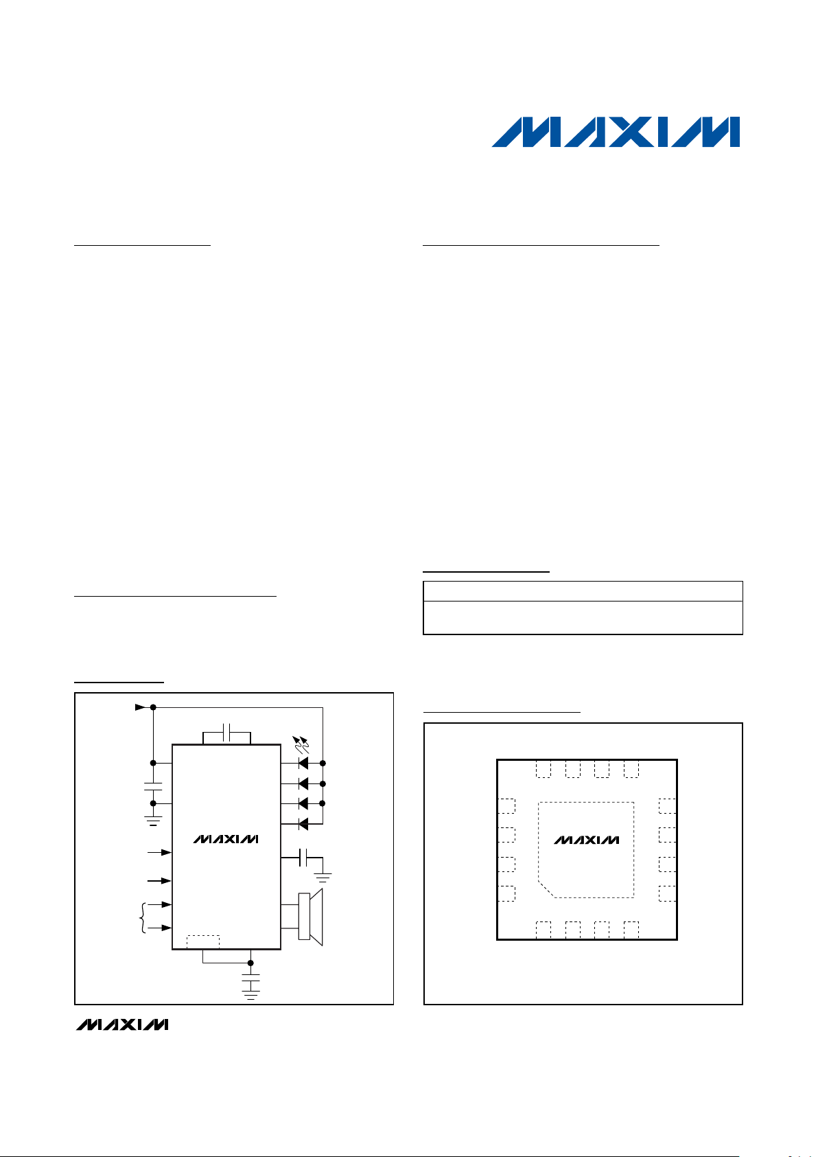
MAX8678
C+
INPUT
2.7V TO 5.5V
LED ON/OFF
AND DIMMING
AMP ON/OFF
AND GAIN
DIFFERENTIAL
AUDIO
INPUT
C-
LED1
LED2
LED3
IN
BACKLIGHT
OR FLASH
0.1mA TO
24mA
LOUDSPEAKER
8Ω
GND
ENLED
LED4
BIAS
OUT+
OUT-
NEGEP
0.1μF
1μF
1μF
4.7μF
ENAMP
A+
A-
Typical Operating Circuit
19-0786; Rev 0; 4/07
For pricing, delivery, and ordering information, please contact Maxim/Dallas Direct! at
1-888-629-4642, or visit Maxim’s website at www.maxim-ic.com.
PART
PIN-PACKAGE TOP MARK
PKG CODE
MAX8678ETE+
16 Thin QFN
3mm x 3mm
AFF T1633-5
+
Denotes a lead-free package.
Note: The device is specified over the -40°C to +85°C extended temperature range.
Page 2
MAX8678
White LED Charge Pump with
1.1W Audio Amplifier
2 _______________________________________________________________________________________
ABSOLUTE MAXIMUM RATINGS
ELECTRICAL CHARACTERISTICS
(VIN= 3.6V, V
GND
= 0V, TA= -40°C to +85°C, unless otherwise noted. Typical values are at TA= +25°C.) (Note 1)
Stresses beyond those listed under “Absolute Maximum Ratings” may cause permanent damage to the device. These are stress ratings only, and functional
operation of the device at these or any other conditions beyond those indicated in the operational sections of the specifications is not implied. Exposure to
absolute maximum rating conditions for extended periods may affect device reliability.
IN to GND ..............................................................-0.3V to +6.0V
IN to NEG ..............................................................-0.3V to +6.0V
ENLED, ENAMP, LED_, C+, A+, A-, OUT+, OUT-,
BIAS to GND…….....................................-0.3V to (V
IN
+ 0.3V)
ENLED, ENAMP, LED_, C+, A+, A-, OUT+, OUT-,
BIAS, C- to NEG...................................…-0.3V to (V
IN
+ 0.3V)
GND to NEG ......................................................…-0.3V to +6.0V
GND to C-..............................................................-0.3V to +6.0V
OUT+, OUT- Short Circuit to GND or IN ....................Continuous
Continuous Power Dissipation (T
A
= +70°C)
16-Pin Thin QFN 3mm x 3mm
(derate 17.5mW/°C above +70°C)............................1398mW
Junction Temperature......................................................+150°C
Storage Temperature Range .............................-65°C to +150°C
Lead Temperature (soldering, 10s) .................................+300°C
PARAMETER CONDITIONS MIN TYP MAX UNITS
IN Operating Voltage 2.7 5.5 V
Undervoltage-Lockout (UVLO) Threshold VIN rising 2.25 2.45 2.65 V
UVLO Hysteresis 100 mV
TA = +25°C 0.1 1.5
Shutdown Supply Current
(All Outputs Off)
ENLED = ENAMP =
GND
T
A
= +85°C 0.1
µA
Charge pump inactive, LED_ = 1.6mA
ENAMP = GND, T
A
= +25°C
140 200 µA
Charge pump active, 1MHz switching, LEDs at
24mA setting, ENAMP = GND
0.45
No-Load Supply Current
ENAMP = IN, ENLED = GND 3
mA
Thermal Shutdown +160 °C
Thermal-Shutdown Hysteresis 20 °C
SERIAL-PULSE INTERFACE (EN_)
VIN = 2.7V to 4.2V 1.4
Logic Input-High Voltage
V
IN
= 4.2V to 5.5V 1.5
V
Logic Input-Low Voltage VIN = 2.7V to 5.5V 0.4 V
TA = +25°C 0.01 1
Logic Input Current
V
IL
= 0V or
V
IH
= 5.5V
T
A
= +85°C 0.1
µA
t
SHDN
See Figures 2 and 3 3.2 ms
t
HOLD
See Figures 2 and 3 3.2 ms
t
LO
See Figures 2 and 3 0.5 500 µs
t
HI
See Figures 2 and 3 0.5 500 µs
CHARGE PUMP
Switching Frequency 1 MHz
Soft-Start Time 0.1 ms
Regulation Voltage (OVP) (VIN - V
NEG
)5V
Open-Loop NEG Output Resistance
((V
NEG
-VIN)/I
NEG
)
10 23 Ω
Guaranteed Output Current LED VF = 3.9V, VIN = 3.2V 96 mA
NEG Discharge Resistance in Shutdown All LEDs off, ENLED = GND 10 kΩ
Page 3

MAX8678
White LED Charge Pump with
1.1W Audio Amplifier
_______________________________________________________________________________________ 3
Note 1: Limits are 100% production tested at TA= +25°C. Limits over the operating temperature range are guaranteed by design.
Note 2: Dropout voltage is defined as the LED_ to GND (charge pump inactive) or LED_ to NEG (charge pump active) voltage at
which current into LED_ drops 10% from the value at V
LED_
= 0.5V.
Note 3: Output power is specified by a combination of a functional output current test and characterization analysis.
PARAMETER CONDITIONS MIN TYP MAX UNITS
LED DRIVER
Current-Setting Range 0.1 24.0 mA
24mA setting, TA = +25°C -2 ±1 +2
24mA setting, TA = -40°C to +85°C -5 +5
Current Accuracy
1.6mA setting, T
A
= +25°C ±5
%
Charge pump inactive 72 120
LED_ Dropout 24mA setting (Note 2)
Charge pump active 132 360
mV
LED_ Voltage-Mode Transition Threshold
(1x to 2x)
V
LED_
falling 125 150 175 mV
LED_ Voltage-Mode Transition
Hysteresis
100 mV
TA = +25°C 0.01 1
LED_ Leakage in Shutdown All LEDs off
T
A
= +85°C 0.1
µA
AUDIO AMPLIFIER
Common-Mode Bias Voltage -5% V
IN
/ 2 +5%
Output Offset Voltage VA+ = VA- = V
BIAS
, gain ≤ 12dB -25 ±1 +25 mV
Common-Mode Input Voltage 0.5
(V
IN
-
1.2)
V
Input Impedance (RIN) Table 2 10 67 140 kΩ
VIN = 3.2V 50 60
Common-Mode Rejection Ratio
f = 1kHz, V
IN
= 3.2V 70
dB
f = 217Hz 93
Power-Supply Rejection Ratio
V
A+
= VA- = V
BIAS
,
200mV
P-P
at IN
f = 1kHz 90
dB
RL = 8Ω, VIN = 3.2V 0.36 0.5
RL = 4Ω, VIN = 3.2V 0.65Output Power
THD+N = 1%,
f = 1kHz (Note 3)
R
L
= 8Ω, VIN = 5V 0.8 1.1
W
Output Current Limit 0.6 1 1.6 A
-9dB ≤ Gain ≤ 15dB ±0.13
Gain Accuracy
Gain = 18dB ±0.17
dB
Total Harmonic Distortion + Noise RL = 8Ω, f = 1kHz, P
OUT
= 0.25W, VIN = 3.2V 0.004 %
Signal-to-Noise Ratio RL = 8Ω, f = 1kHz, P
OUT
= 0.25W, VIN = 3.2V 104 dB
Maximum Capacitive Drive 500 pF
Power-Up from Shutdown Time, t
UP
See Figure 3 10 ms
Shutdown Time, t
PD
See Figure 3 3.5 µs
ELECTRICAL CHARACTERISTICS (continued)
(VIN= 3.6V, V
GND
= 0V, TA= -40°C to +85°C, unless otherwise noted. Typical values are at TA= +25°C.) (Note 1)
Page 4
MAX8678
White LED Charge Pump with
1.1W Audio Amplifier
4 _______________________________________________________________________________________
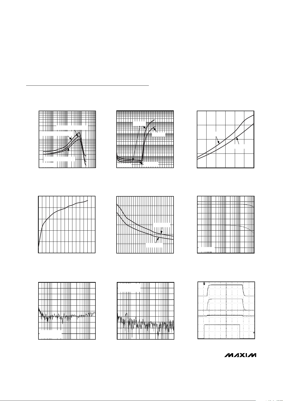
Typical Operating Characteristics
(VIN= 3.2V, RL= 8Ω, TA= +25°C, unless otherwise noted.)
TOTAL HARMONIC DISTORTION +
NOISE vs. FREQUENCY
MAX8678 toc01
FREQUENCY (Hz)
THD+N (%)
10,0001000100
0.01
10 100,000
0.1
0.001
OUTPUT POWER = 150mW
OUTPUT POWER = 50mW
OUTPUT POWER = 300mW
GAIN = 3dB
TOTAL HARMONIC DISTORTION +
NOISE vs. OUTPUT POWER
MAX8678 toc02
OUTPUT POWER (W)
THD+N (%)
0.80.60.40.2
0.01
0.1
1
10
100
0.001
01.0
fIN = 1kHz
fIN = 10kHz
fIN = 100kHz
GAIN = 3dB
2000
1000
0
2.5 3.5 4.5 5.5
OUTPUT POWER vs. SUPPLY VOLTAGE
MAX8678 toc03
SUPPLY VOLTAGE (V)
OUTPUT POWER (mW)
THD+N = 10%
THD+N = 1%
0
100
300
200
400
500
0 200100 300 400 500 600 700
POWER DISSIPATION vs. OUTPUT POWER
MAX8678 toc04
OUTPUT POWER (mW)
POWER DISSIPATION POWER (mW)
0
0.4
0.2
0.8
0.6
1.0
1.2
48106 121416
OUTPUT POWER vs. LOAD RESISTANCE
MAX8678 toc05
LOAD RESISTANCE (Ω)
OUTPUT POWER (W)
THD+N = 10%
THD+N = 1%
FREQUENCY (Hz)
AMPLIFIER GAIN AND PHASE
vs. FREQUENCY
25dB
20dB
15dB
10dB
5dB
0dB
0°
-30°
-60°
-90°
MAX8678 toc06
GAIN = 18dB
10 100 1k 10k 100k
AMPLIFIER GAIN AND PHASE
FREQUENCY (Hz)
COMMON-MODE REJECTION RATIO
vs. FREQUENCY
-25dB
-35dB
-45dB
-55dB
-65dB
-75dB
-85dB
-95dB
MAX8678 toc07
GAIN = 18dB
V
RIPPLE
100mV
P-P
100 1k 10k
REJECTION RATIO
FREQUENCY (Hz)
POWER-SUPPLY REJECTION RATIO
vs. FREQUENCY
-25dB
-35dB
-45dB
-55dB
-65dB
-75dB
-85dB
-95dB
-105dB
-125dB
MAX8678 toc08
GAIN = 18dB
V
RIPPLE
18mV
P-P
100 1k 10k
REJECTION RATIO
4ms/div
AMPLIFIER STARTUP
AND SHUTDOWN
V
OUT+
V
OUT-
V
OUT+
- V
OUT-
MAX8678 toc09
V
ENAMP
2V/div
100mV/div
1V/div
1V/div
Page 5

MAX8678
White LED Charge Pump with
1.1W Audio Amplifier
_______________________________________________________________________________________
5
0
30
20
10
40
50
60
70
80
90
100
2.7 3.33.0 3.6 3.9 4.2
LED EFFICIENCY vs. SUPPLY VOLTAGE
(MISMATCHED LEDs)
MAX8678 toc10
SUPPLY VOLTAGE (V)
EFFICIENCY (%)
4 x 1.6mA
4 x 6.4mA
4 x 20.8mA
0
60
40
20
80
100
120
140
160
180
200
4.2 3.63.9 3.3 3.0 2.7
SUPPLY CURRENT vs. SUPPLY VOLTAGE
(MISMATCHED LEDs)
MAX8678 toc11
SUPPLY VOLTAGE (V)
SUPPLY CURRENT (mA)
4 x 16mA
4 x 20.8mA
4 x 6.4mA
4 x 1.6mA
0
30
20
10
40
50
60
70
80
90
100
2.7 3.33.0 3.6 3.9 4.2
LED EFFICIENCY vs. SUPPLY VOLTAGE
(MATCHED LEDs)
MAX8678 toc12
SUPPLY VOLTAGE (V)
EFFICIENCY (%)
20.4mA/LED
16.4mA/LED
6.4mA/LED
1.6mA/LED
40
60
50
80
70
90
100
4.20
3.90
3.85
3.80
3.75
3.70
3.65
3.60
3.55
3.50
3.40
3.00
MAX8678 EFFICIENCY vs. SUPPLY VOLTAGE
(MATCHED LEDs)
MAX8678 toc13
SUPPLY VOLTAGE, TIME WEIGHTED (V)
EFFICIENCY
1.6mA/LED
6.4mA/LED
16.4mA/LED
20.4mA/LED
15.0
15.6
15.4
15.2
15.8
16.0
16.2
16.4
16.6
16.8
17.0
2.7 3.33.0 3.6 3.9 4.2
LED CURRENT MATCHING
vs. SUPPLY VOLTAGE
MAX8678 toc14
SUPPLY VOLTAGE (V)
LED CURRENT (mA)
4 OF 16mA/LED
1ms/div
LED STARTUP/
SHUTDOWN WAVEFORMS
V
ENLED
V
LED1
MAX8678 toc15
I
IN
500mA/div
1V/div
2V/div
Typical Operating Characteristics (continued)
(VIN= 3.2V, RL= 8Ω, TA= +25°C, unless otherwise noted.)
Page 6

MAX8678
White LED Charge Pump with
1.1W Audio Amplifier
6 _______________________________________________________________________________________
Pin Description
PIN NAME FUNCTION
1IN
Analog Supply-Voltage Input. The input voltage range is 2.7V to 5.5V. Connect a 4.7µF ceramic
capacitor from IN to GND as close as possible to the IC. IN is high impedance during shutdown.
2 GND Ground. Connect GND to the system ground plane. Do not connect GND to the exposed paddle.
3 A+ Noninverting Differential Audio Input
4 A- Inverting Differential Audio Input
5 ENAMP
Amplifier Enable and Gain Control. ENAMP is a serial-pulse interface logic input to control on/off and
gain settings of the audio amplifier.
6 OUT+ Audio Amplifier Positive Output
7 OUT- Audio Amplifier Negative Output
8 BIAS DC Bias Bypass. Connect a 0.1µF ceramic capacitor from BIAS to GND as close as possible to the IC.
9–12 LED1–LED4
LED Current Regulators. Current flowing into LED_ is regulated to the current programmed by the
serial-pulse interface. Connect LED_ to the cathodes of the corresponding external LEDs. LED_ is high
impedance during shutdown. If unused, connect LED_ to IN to disable the regulator.
13 NEG
Charge-Pump Negative Output. Connect a 1µF ceramic capacitor from NEG to GND. In shutdown, an
internal 10kΩ resistor pulls NEG to GND.
14 C- Transfer Capacitor Negative Connection. Connect a 1µF ceramic capacitor from C+ to C-.
15 C+ Transfer Capacitor Positive Connection. Connect a 1µF ceramic capacitor from C+ to C-.
16 ENLED
LED Enable and Dimming Control. ENLED is a serial-pulse interface logic input to control on/off and
dimming of the LED regulators.
— EP Exposed Paddle. Connect the exposed paddle to NEG directly under the IC.
Typical Operating Characteristics (continued)
(VIN= 3.2V, RL= 8Ω, TA= +25°C, unless otherwise noted.)
200ms/div
LED SINGLE-WIRE PULSE DIMMING
V
ENLED
I
LED
MAX8678 toc16
20mA/div
5V/div
200μs/div
LINE TRANSIENT WITH MODE
TRANSITION
V
IN
I
LED
(TOTAL)
MAX8678 toc17
I
IN
200mA/div
100mA/div
1V/div
3.8V
3.4V
3.8V
4 LEDs AT 24mA EACH
Page 7

Detailed Description
The MAX8678 integrates a charge pump for white LEDs
with an audio loudspeaker amplifier. The high-efficiency,
adaptive charge pump drives up to four LEDs with constant current for uniform brightness for display backlighting or camera flash. The LED current is adjustable
from 0.1mA/LED to 24mA/LED in 31 pseudo-logarithmic
steps through a single-wire serial-pulse interface. High
accuracy and LED-to-LED current matching are maintained throughout the adjustment range. Figure 1 is the
MAX8678 functional diagram.
The mono class AB audio amplifier directly drives an 8Ω
loudspeaker with 1.1W RMS continuous power from a 5V
supply with less than 1% THD+N. The gain is adjustable
from -9dB to +18dB in ten 3dB steps through a singlewire serial-pulse interface. Clicks and pops are suppressed during on/off and all gain adjustments.
Differential inputs improve common-mode noise rejection.
Shutdown
To reduce power consumption when not in use, the
charge-pump LED driver and the audio amplifier have
separate shutdown controls. To disable the LED driver,
drive ENLED low for at least 3.2ms. To disable the
audio amplifier, drive ENAMP low for at least 3.2ms.
When both ENLED and ENAMP are held low, the IC
supply current is reduced to about 0.1µA.
Thermal-Overload Protection
The thermal-overload protection circuitry monitors the
temperature of the IC. When the die temperature reaches +160°C, the IC is shut down. The IC turns on after it
has cooled by approximately 20°C. During continuous
overload conditions, this results in a pulsed output.
MAX8678
White LED Charge Pump with
1.1W Audio Amplifier
_______________________________________________________________________________________ 7
_______________________________________________________________________________________
7
MAX8678
C+
LED ON/OFF
AND DIMMING
AMP ON/OFF
AND GAIN
DIFFERENTIAL
AUDIO INPUT
OPTIONAL FILTER
CAPACITORS
C-
LED1
LED2
LED3
LED4
NEG
IN
INVERTING
CHARGE
PUMP
EARPIECE/
LOUDSPEAKER
GND
ENLED
BIAS
OUT+
OUT-
C4
0.1μF
C3
1μF
C1
4.7μF
2.7V TO 5.5V
INPUT SUPPLY
ENAMP
A+
A-
HALF
SUPPLY
BIAS
MONO
CLASS AB
AUDIO AMP
CONTROL
CIRCUITRY
LED CURRENT
REGULATORS
CONTROL
CIRCUITRY
C2
1μF
Figure 1. Functional Diagram
Page 8

MAX8678
White LED Charge Pump with
1.1W Audio Amplifier
8 _______________________________________________________________________________________8 _______________________________________________________________________________________
LED Charge Pump
The charge pump drives up to four white LEDs with
regulated constant current for displaying backlight
applications. By utilizing an adaptive charge pump and
extremely low-dropout current regulators, it achieves
high efficiency over the full 1-cell lithium ion (Li+) battery input-voltage range. Fixed frequency of 1MHz
switching allows for tiny external components. The regulation scheme is optimized to ensure low EMI and low
input ripple.
Adaptive Charge-Pump Modes
When the supply voltage is sufficient to drive the LEDs,
the charge pump is turned off to minimize the input
supply current and the LED currents are linearly regulated. When the supply voltage is insufficient to drive
the LEDs at the set current, the charge pump is
enabled, creating a negative voltage at NEG and allowing the LED_ outputs to pull below ground to maintain
the set LED current.
Low LED Current Levels
The MAX8678 internally generates a PWM signal to
obtain higher resolution at lower currents. As the I
LED
setting is below 6.4mA, the IC adjusts I
LED
DC current,
and the duty cycle is controlled by the PWM signal. The
frequency of the PWM dimming signal is set at 1kHz
with a minimum duty cycle of 1/16 to avoid the LED
flicking effect to human eyes. Table 1 shows the current
level and the corresponding duty cycle.
Soft-Start and Shutdown
The MAX8678 LED driver features a low-power shutdown mode for reduced current consumption. Hold
ENLED low for 3.2ms to enter shutdown mode. This disables the charge pump and the LED current drivers.
When initially powering the MAX8678, or when starting
up from shutdown mode, a soft-start feature prevents
input current overshoot. See the startup waveforms in
the
Typical Operating Characteristics
section.
Serial-Pulse Dimming Control (ENLED)
The MAX8678 includes a serial-pulse logic interface for
on/off and dimming of the backlight. The dimming
range is pseudo-logarithmic from 24mA to 0.1mA in 31
steps. Driving ENLED high turns on the IC and sets the
internal register to 24.0mA. To dim the MAX8678, pulse
ENLED low (500ns to 500µs pulse width). Each rising
edge sets the LED current setting as shown in Table 2.
Once the desired setting is reached, hold ENLED high
for at least 3.2ms to set the internal register and the
LED current changes. To set a new current level, repeat
the previous sequence from the beginning.
To turn off the LEDs, hold ENLED low for at least 3.2ms.
Figure 2 shows a timing diagram for ENLED.
If dimming control is not required, ENLED works as a
simple on/off logic control. Drive ENLED high for at
least 3.2ms to enable the LEDs, or drive ENLED low for
at least 3.2ms for shutdown. The LED driver operates at
100% brightness under or OFF under these conditions.
ENLED
INTERNAL
CURRENT
SETTING
I
LED_
OFF
12 34 1 23 1314
OFF
24.0mA 22.4mA 20.8mA 19.2mA
t
HOLD
t
HI
t
LO
24.0mA
19.2mA
4.8mA
OFF
22.4mA 20.8mA 5.6mA 4.8mA
3.2ms
t
HOLD
3.2ms
t
SHDN
t
HI
= 500ns TO 500μs
t
LO
= 500ns TO 500μs
OFF
3.2ms
Figure 2. Serial-Pulse Dimming
I
LED
(mA)
DUTY CYCLE
(n/16)
I
LED
(mA)
DUTY CYCLE
(n/16)
6.4 16 1.2 12
5.6 14 1.0 10
4.8 12 0.8 8
4.0 10 0.7 7
3.2 16 0.6 6
2.8 14 0.5 5
2.4 12 0.4 4
2.0 10 0.3 3
1.6 16 0.2 2
1.4 14 0.1 1
Table 1. Internal PWM Duty Cycle vs. LED
Set Current
Page 9

MAX8678
White LED Charge Pump with
1.1W Audio Amplifier
_______________________________________________________________________________________ 9
Open-Circuit and Short-Circuit Protection
The short-circuit protection detects when an LED is
shorted and disables the corresponding current regulator to avoid wasting battery power. If any LED fails as an
open circuit, the charge pump is forced on and the corresponding LED_ pin is internally connected to NEG.
Audio Amplifier
The MAX8678 contains a 1.1W RMS DirectDrive mono
speaker amplifier. It features a low-power shutdown
mode and click-and-pop suppression.
Bias
An internally generated common-mode BIAS voltage of
V
IN
/ 2 sets the DC bias level for the audio outputs. The
BIAS capacitor (C4 in Figure 1) improves PSRR and
THD+N by reducing power supply and other noise
sources at the common-mode bias node, and also
generates the clickless/popless startup DC bias waveform for the speaker amplifier. A 0.1µF BIAS capacitor
is recommended for most applications. Increasing C4
to 1µF slows turn-on and turn-off times by a factor of 10
and improves PSRR by 20dB (at 1kHz). Do not connect
external loads to BIAS.
Shutdown Mode
The MAX8678 audio amplifier features a low-power shutdown mode for reduced current consumption. Hold
ENAMP low for 3.2ms to shut down the audio amplifier.
Entering shutdown disables the amplifier’s bias circuitry,
causes the audio outputs to go high impedance, and
drives BIAS to GND.
Click-and-Pop Suppression
The MAX8678 features Maxim’s industry-leading clickand-pop suppression circuitry. During startup, the amplifier common-mode bias voltage ramps to the DC bias
point. When entering shutdown, the amplifier outputs are
high impedance to 100kΩ between the outputs. This
scheme minimizes the energy present in the audio band.
_______________________________________________________________________________________ 9
ENLED
RISING
EDGES
LED CURRENT
(mA)
ENLED
RISING
EDGES
LED CURRENT
(mA)
1 24.0 17 2.8
2 22.4 18 2.4
3 20.8 19 2.0
4 19.2 20 1.6
5 17.6 21 1.4
6 16.0 22 1.2
7 14.4 23 1.0
8 12.8 24 0.8
9 11.2 25 0.7
10 9.6 26 0.6
11 8.0 27 0.5
12 6.4 28 0.4
13 5.6 29 0.3
14 4.8 30 0.2
15 4.0 31 0.1
16 3.2 — —
Table 2. LED Current Levels
ENAMP
INTERNAL
GAIN
SETTING
GAIN
OFF
OFF
-9dB
-6dB
-3dB
-9dB
1
2
34 123 78
-6dB
-3dB
+9dB
+12dB
+12dB
0dB
0dB
t
HOLD
3.2ms
t
UP
10ms typ
t
UP
10ms (typ)
t
SHDN
3.2ms
t
HOLD
t
LO
t
HI
3.2ms
t
PD
1μs (typ)
t
HI
= 500ns TO 500μs
t
LO
= 500ns TO 500μs
OFF
OFF
Figure 3. Serial-Pulse Gain Adjustment
Page 10

MAX8678
Serial-Pulse Gain Adjustment (ENAMP)
The audio amplifier has an internal gain adjustment,
controlled by a serial-pulse interface. The gain setting
of the input amplifier is adjustable from -9dB to +18dB
in 3dB steps. This allows the amplifier to be used for
both hands-free and for receiver mode, without any
external components.
Driving ENAMP high turns on the amplifier and sets the
internal register to -9dB. Adjust the gain by pulsing
ENAMP low (500ns to 500µs pulse width). Each rising
edge sets the gain as shown in Table 3. Once the
desired setting is reached, hold ENAMP high for at
least 3.2ms to set the internal register and change the
gain. To set a new current level, repeat the previous
sequence from the beginning. To shut down the amplifier, hold ENAMP low for at least 3.2ms. Figure 3 is a
timing diagram for ENAMP.
Applications Information
BTL Amplifier
The MAX8678 is designed to drive a load differentially,
a configuration referred to as bridge-tied load (BTL).
The BTL configuration offers advantages over the single-ended configuration, where one side of the load is
connected to ground. Driving the load differentially
doubles the output voltage, thus quadrupling output
power compared to a single-ended amplifier under
similar configurations.
Since the differential outputs are biased at midsupply,
there is no net DC voltage across the load. This eliminates the need for DC-blocking capacitors required for
single-ended amplifiers. These capacitors can be
large, expensive, consume board space, and degrade
low-frequency performance.
White LED Charge Pump with
1.1W Audio Amplifier
10 ______________________________________________________________________________________
OPTIONAL FILTER
CAPACITORS
DIFFERENTIAL
AUDIO INPUT
MONO
CLASS AB
AUDIO AMP
EARPIECE /
LOUDSPEAKER
R
IN
R
IN
A+
A-
OUT+
OUT-
MAX8678
Figure 4. Differential Audio Input with Optional Filter Capacitors
SINGLE-ENDED
AUDIO INPUT
MONO
CLASS AB
AUDIO AMP
EARPIECE /
LOUDSPEAKER
R
IN
R
IN
A+
A-
OUT+
OUT-
MAX8678
NOTE: FILTER CAPACITORS REQUIRED FOR SINGLE-ENDED AUDIO OUTPUT.
Figure 5. Single-Ended Audio Input
RIN (kΩ)
ENAMP
RISING
EDGES
GAIN
SETTING
(dB)
MIN TYP MAX
1 -9 69.1 99.0 140.0
2 -6 62.4 89.2 116.0
3 -3 54.9 78.4 102.0
4 0 46.8 66.9 87.0
5 3 38.8 55.5 72.1
6 6 31.3 44.7 58.1
7 9 24.6 35.1 45.6
8 12 18.8 26.9 35.0
9 15 14.1 20.2 26.2
10 18 10.5 15.0 19.5
Table 3. Audio Amplifier-Input Impedance
Page 11

Input Filter
The fully differential amplifier inputs can be biased at
voltages other than midsupply. The common-mode
feedback circuit adjusts for input bias, ensuring the
outputs are still biased at midsupply. Input capacitors
are not required as long as the common-mode input
voltage is within the specified range listed in the
Electrical Characteristics
.
If input capacitors are used (see Figure 4), the input
capacitor in conjunction with the amplifier input impedance (RIN) form a highpass filter that removes the DC
bias from an incoming signal. The AC-coupling capacitor
allows the amplifier to bias the signal to an optimum DC
level. Assuming zero-source impedance, the -3dB point
of the highpass filter is given by:
where RINis the input impedance given in Table 2.
Figure 5 shows a single-ended audio input.
Setting f
-3dB
too high affects the low-frequency
response of the amplifier. Use capacitors with
dielectrics that have low-voltage coefficients, such as
tantalum or aluminum electrolytic. Capacitors with high
voltage coefficients, such as ceramics, can increase
distortion at low frequencies.
PCB Layout
Good PC board (PCB) layout is essential for optimizing
performance. Use large traces for the power-supply
inputs and amplifier outputs to minimize losses due to
parasitic trace resistance and to route heat away from
the device. Good grounding improves audio performance and prevents any digital switching noise from
coupling into the audio signal. The exposed paddle lowers the thermal resistance of the package by providing a
direct-heat conduction path from the die to the PCB.
Connect the exposed paddle to NEG directly under the
IC. Refer to the MAX8678 Evaluation Kit for a good PCB
layout example.
f
RC
dB
IN IN
−
=
××
3
1
2π
MAX8678
White LED Charge Pump with
1.1W Audio Amplifier
______________________________________________________________________________________ 11
Chip Information
PROCESS: BiCMOS
Page 12

MAX8678
White LED Charge Pump with
1.1W Audio Amplifier
12 ______________________________________________________________________________________
Package Information
(The package drawing(s) in this data sheet may not reflect the most current specifications. For the latest package outline information
go to www.maxim-ic.com/packages
.)
12x16L QFN THIN.EPS
0.10 C 0.08 C
0.10 M C A B
D
D/2
E/2
E
A1
A2
A
E2
E2/2
L
k
e
(ND - 1) X e
(NE - 1) X e
D2
D2/2
b
L
e
L
C
L
e
C
L
L
C
L
C
PACKAGE OUTLINE
21-0136
2
1
I
8, 12, 16L THIN QFN, 3x3x0.8mm
MARKING
AAAA
Page 13

MAX8678
White LED Charge Pump with
1.1W Audio Amplifier
Maxim cannot assume responsibility for use of any circuitry other than circuitry entirely embodied in a Maxim product. No circuit patent licenses are
implied. Maxim reserves the right to change the circuitry and specifications without notice at any time.
Maxim Integrated Products, 120 San Gabriel Drive, Sunnyvale, CA 94086 408-737-7600 ____________________
13
© 2007 Maxim Integrated Products is a registered trademark of Maxim Integrated Products, Inc.
Package Information (continued)
(The package drawing(s) in this data sheet may not reflect the most current specifications. For the latest package outline information
go to www.maxim-ic.com/packages
.)
EXPOSED PAD VARIATIONS
CODES
PKG.
T1233-1
MIN.
0.95
NOM.
1.10
D2
NOM.
1.10
MAX.
1.25
MIN.
0.95
MAX.
1.25
E2
12N
k
A2
0.25
NE
A1
ND
0
0.20 REF
-
-
3
0.02
3
0.05
L
e
E
0.45
2.90
b
D
A
0.20
2.90
0.70
0.50 BSC.
0.55
3.00
0.65
3.10
0.25
3.00
0.75
0.30
3.10
0.80
16
0.20 REF
0.25
-
040.02
4
-
0.05
0.50 BSC.
0.30
2.90
0.40
3.00
0.20
2.90
0.70
0.25
3.00
0.75
3.10
0.50
0.80
3.10
0.30
PKG
REF. MIN.
12L 3x3
NOM. MAX. NOM.
16L 3x3
MIN. MAX.
0.35 x 45°
PIN
ID
JEDEC
WEED-1
T1233-
3
1.10
1.25
0.95 1.10 0.35 x 45°1.25 WEED-1
0.95
T1633F-3
0.65
T1633-4 0.95
0.80
0.95
0.65
0.80
1.10 1.25 0.95 1.10
0.225 x 45°
0.95
WEED-2
0.35 x 45°
1.25
WEED-2
T1633-2 0.95
1.10
1.25
0.95
1.10
0.35 x 45°
1.25
WEED-2
PACKAGE OUTLINE
21-0136
2
2
I
8, 12, 16L THIN QFN, 3x3x0.8mm
WEED-11.25
1.100.95
0.35 x 45°
1.251.10
0.95
T1233-4
T1633FH-3 0.65 0.80 0.95
0.225 x 45°
0.65 0.80
0.95
WEED-2
NOTES:
1. DIMENSIONING & TOLERANCING CONFORM TO ASME Y14.5M-1994.
2. ALL DIMENSIONS ARE IN MILLIMETERS. ANGLES ARE IN DEGREES.
3. N IS THE TOTAL NUMBER OF TERMINALS.
4. THE TERMINAL #1 IDENTIFIER AND TERMINAL NUMBERING CONVENTION SHALL CONFORM TO
JESD 95-1 SPP-012. DETAILS OF TERMINAL #1 IDENTIFIER ARE OPTIONAL, BUT MUST BE LOCATED
WITHIN THE ZONE INDICATED. THE TERMINAL #1 IDENTIFIER MAY BE EITHER A MOLD OR
MARKED FEATURE.
5. DIMENSION b APPLIES TO METALLIZED TERMINAL AND IS MEASURED BETWEEN 0.20 mm AND 0.25 mm
FROM TERMINAL TIP.
6. ND AND NE REFER TO THE NUMBER OF TERMINALS ON EACH D AND E SIDE RESPECTIVELY.
7. DEPOPULATION IS POSSIBLE IN A SYMMETRICAL FASHION.
8. COPLANARITY APPLIES TO THE EXPOSED HEAT SINK SLUG AS WELL AS THE TERMINALS.
9. DRAWING CONFORMS TO JEDEC MO220 REVISION C.
10. MARKING IS FOR PACKAGE ORIENTATION REFERENCE ONLY.
11. NUMBER OF LEADS SHOWN ARE FOR REFERENCE ONLY.
12. WARPAGE NOT TO EXCEED
0.10mm.
0.25 0.30 0.35
2
0.25
0
0.20 REF
-
-
0.02
0.05
0.35
8
2
0.55 0.75
2.90
2.90 3.00 3.10
0.65 BSC.
3.00 3.10
8L 3x3
MIN.
0.70 0.75 0.80
NOM. M
AX.
TQ833-1 1.250.25 0.70 0.35 x 45° WEEC1.250.700.25
T1633-5 0.95
1.10
1.25
0.35 x 45°
WEED-20.95
1.10
1.25
 Loading...