

Page 1
General Description
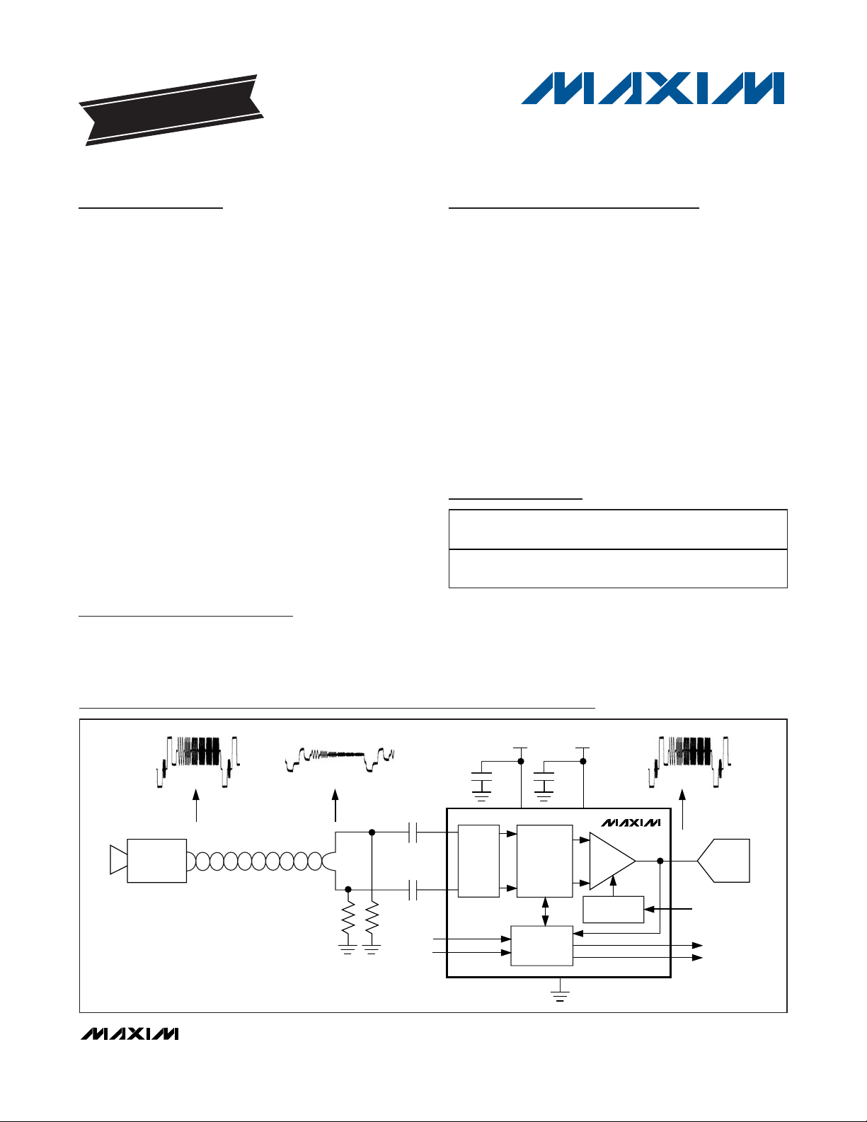
The MAX7474 adaptive equalizer recovers losses
incurred in the transmission of a composite video
(CVBS) signal over unshielded twisted-pair (UTP)
cable. The device fully recovers losses for cable
lengths of up to 300m and greatly improves signal quality for cable lengths of up to 600m. The device automatically adapts to all cable lengths for CVBS signals with
color burst and allows fixed-equalization settings for
video signals without burst. The MAX7474 is optimized
to provide compensation for losses that occur when
transmitting composite video signals over UTP cables
such as Category 5e. The device compensates for low
frequency and chroma band losses. The MAX7474 is
compatible with NTSC and PAL standards.
The MAX7474 accepts differential input and provides a
single-ended output. The output is capable of driving
two AC- or DC-coupled standard 150Ω video loads.
The output back-porch DC level is adjustable with an
externally applied DC voltage at the BPLVL input. The
device also features loss-of-sync (LOS) and loss-of-burst
(LOB) logic outputs.
The MAX7474 is available in a 16-pin SSOP package
and is fully specified over the extended (-40°C to
+85°C) temperature range.
Applications
Security Video Systems
Video Switching Systems
Home Automation
Features
♦ Automatically Equalizes Up to 600m
(Fully Recovers Losses Up to 300m) of UTP Cable
Carrying CVBS
♦ Automatic Switchover to Fixed Equalization for
CVBS Without Color Burst
♦ Integrated Video Driver with Adjustable
Back-Porch Clamp Level
♦ LOS and LOB Output
♦ NTSC and PAL Compatible
♦ 16-Pin SSOP Package
MAX7474
Adaptive Equalizer for
Video Over Twisted Pair
________________________________________________________________
Maxim Integrated Products
1
19-3216; Rev 0; 1/08
For pricing, delivery, and ordering information, please contact Maxim Direct at 1-888-629-4642,
or visit Maxim’s website at www.maxim-ic.com.
EVALUATION KIT
AVAILABLE
Ordering Information
+
Denotes a lead-free package.
Functional Diagram
Pin Configuration and Typical Application Circuit appear at
end of data sheet.
PART TEMP RANGE PIN-PACKAGE
MAX7474EAE+ -40°C to +85°C
16 SSOP
(5.3mm x 6.2mm)
PKG
CODE
A16+2
GND
0.1µF
V
+5V
CC
MAX7474
OUT
BACK-PORCH
CLAMP
BPLVL (1.0V TO 1.6V)
LOB
LOS
ADC
+5V
0.1µF
V
CC
0.022µF
0.022µF
INP
INN
FEQ0
FEQ1
CLAMP
ADAPTIVE
EQUALIZER
AGC AND AEQ
CONTROL
UNSHIELDED TWISTED PAIR
(0 TO 300m)
CAMERA
50Ω
50Ω
Page 2
MAX7474
Adaptive Equalizer for
Video Over Twisted Pair
2 _______________________________________________________________________________________
ABSOLUTE MAXIMUM RATINGS
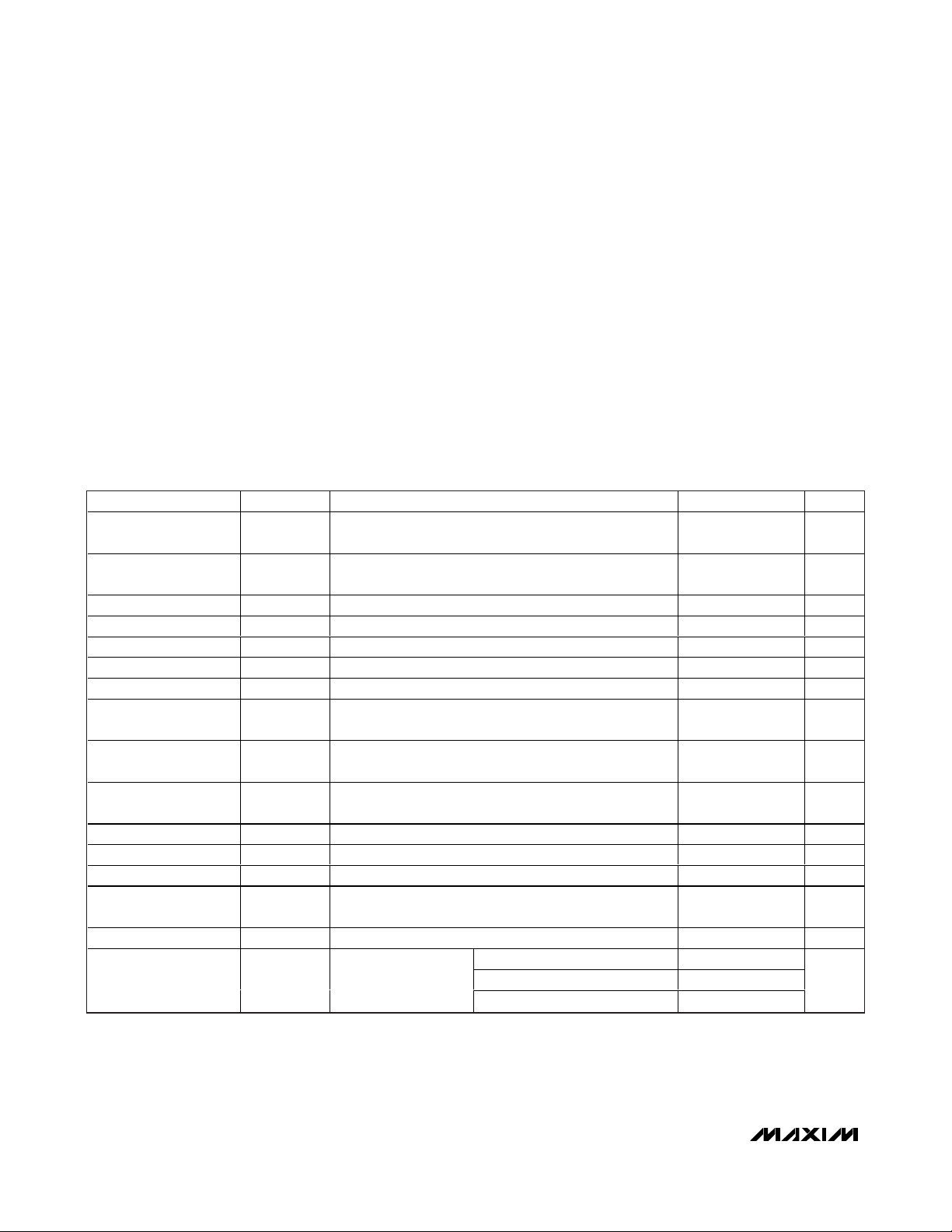
ELECTRICAL CHARACTERISTICS
(VCC= +4.75V to +5.25V, RL= 150Ω (AC-coupled), FEQ1 = GND, FEQ0 = GND, V
BPLVL
= 1.4V, TA= -40°C to +85°C, unless otherwise
noted. Typical values are at T
A
= +25°C.)
Stresses beyond those listed under “Absolute Maximum Ratings” may cause permanent damage to the device. These are stress ratings only, and functional
operation of the device at these or any other conditions beyond those indicated in the operational sections of the specifications is not implied. Exposure to
absolute maximum rating conditions for extended periods may affect device reliability.
VCCto GND..............................................................-0.3V to +6V
All Other Pins to GND.............-0.3V to (min of 6V or V
CC
+ 0.3V)
Maximum Continuous Current into Any Input or Output .....±50mA
Continuous Power Dissipation (T
A
= +70°C)
16-Pin SSOP (derate 7.1mW/°C above +70°C) ........571.4mW
Operating Temperature Range ...........................-40°C to +85°C
Maximum Junction Temperature .....................................+150°C
Storage Temperature Range .............................-65°C to +150°C
Lead Temperature (soldering, 10s) .................................+300°C
PARAMETER SYMBOL CONDITIONS MIN TYP MAX UNITS
Differential Input
Operating Voltage
Maximum Differential
Input Operating Voltage
Output Voltage V
Output Sync Accuracy V
Output Burst Accuracy V
Differential Phase DP 0.3 Degrees
Differential Gain DG 0.3 %
Clamp Settling Time t
Back-Porch Level Input
Operating Range
Output Blank Level
Accuracy
Line-Time Distortion LTD 18µs, 100 IRE bar, DC-coupled output 1.2 %
LOS Threshold V
LOB Threshold V
Equalizer Response
Time
OUT Leakage Current I
Fixed Equalizer Gain A
V
IN-DIFF
OUT
SYNC_OUT
BURST_OUT
CLAMP
V
BPLVL
∆V
OUT-BL
LOS
LOB
t
EQ
LEAK
FEQ
AC-coupled, measured from sync tip to 100% white level
(Note 1)
AC-coupled, measured from sync tip to 100% white level 2.4 V
Measured from sync tip to 100% white level 1.0 V
210mV
76mV
Output blank level settles to < 5 IRE of final value from an
initial 100 IRE input error
(Note 2) ±55 mV
Measured differentially between INP and INN (Note 3) 40 mV
Measured at OUT with maximum equalizer gain (Note 4) 80 mV
Within ±10% of final value of the combined AGC and
AEQ gain from minimum to maximum
LOS mode, OUT is three-stated ± 0.01 ±10 µA
fSC = 3.58MHz
P-P
P-P
< V
< V
SYNC_IN-DIFF
BURST_IN-DIFF
1.0 V
< 600mV
< 300mV
FEQ1 = GND, FEQ0 = GND -1.5 0 +1.5
FEQ1 = GND, FEQ0 = V
FEQ1 = V
P-P
, fSC = 3.58MHz 242 293 344 mV
P-P
CC
, FEQ0 = GND 8.5 10.5 12.5
CC
263 293 323 mV
9 30 H Lines
1.0 1.6 V
16,384 H Lines
2.5 4.5 6.5
P-P
P-P
P-P
P-P
P-P
P-P
P-P
dB
Page 3
MAX7474
Adaptive Equalizer for
Video Over Twisted Pair
_______________________________________________________________________________________ 3
Note 1: V
IN-DIFF = VINP
- V
INN
.
Note 2: V
OUT-BL = VBPLVL
+ ∆V
OUT-BL
.
Note 3: LOS is high when the input video sync amplitude goes below V
LOS
for 32 consecutive horizontal lines. LOS goes low when
the input video sync amplitude exceeds V
LOS
for 32 consecutive horizontal lines.
Note 4: LOB is high when the output color burst amplitude goes below V
LOB
for 32 consecutive horizontal lines when at maximum
equalizer gain. LOB goes low when the output color burst amplitude exceeds V
LOB
for 32 consecutive horizontal lines.
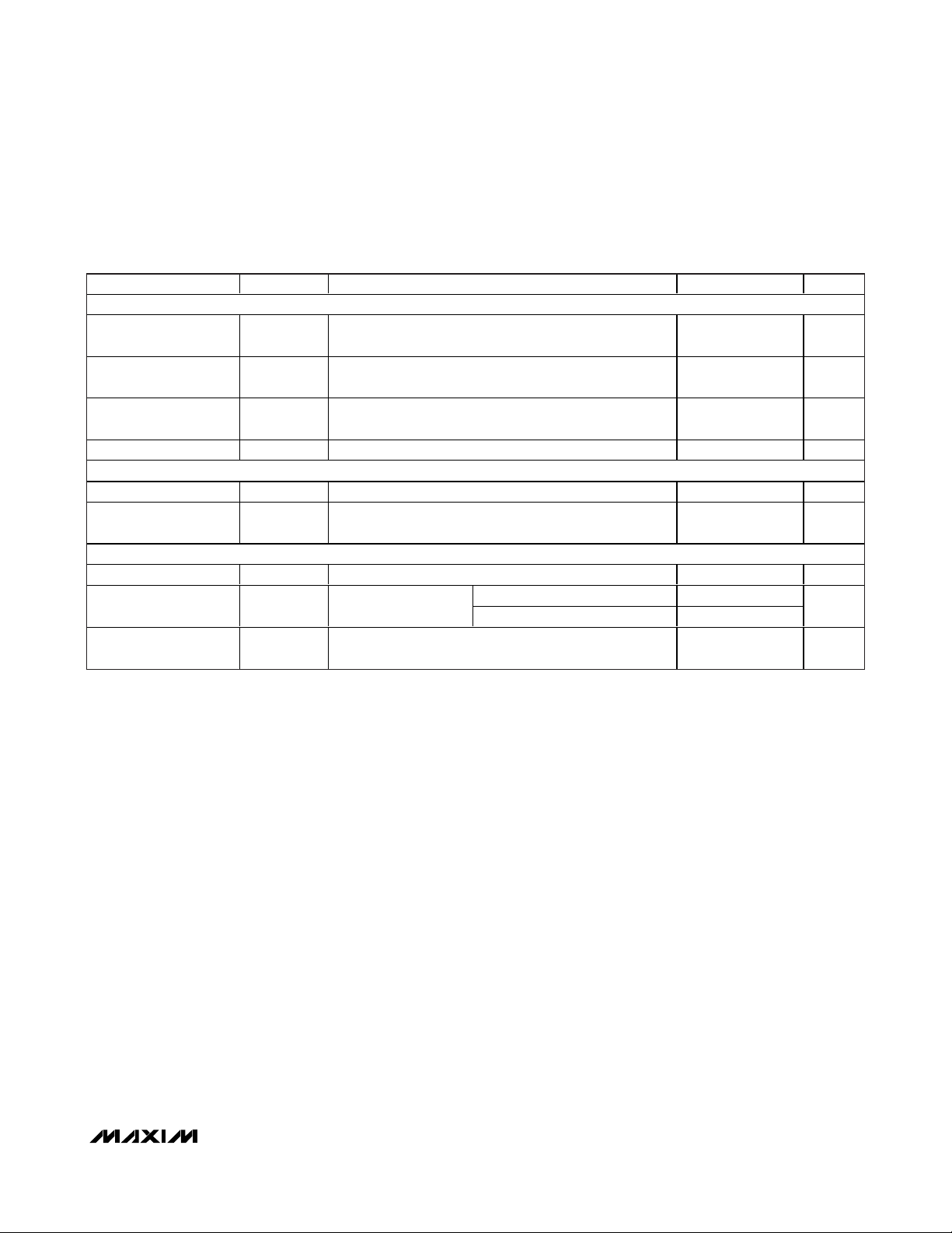
ELECTRICAL CHARACTERISTICS (continued)
(VCC= +4.75V to +5.25V, RL= 150Ω (AC-coupled), FEQ1 = GND, FEQ0 = GND, V
BPLVL
= 1.4V, TA= -40°C to +85°C, unless otherwise
noted. Typical values are at T
A
= +25°C.)
PARAMETER SYMBOL CONDITIONS MIN TYP MAX UNITS
DIGITAL INPUTS (FEQ0, FEQ1)
Input High Voltage V
Input Low Voltage V
Input Leakage Current Digital inputs = 0 or V
Input Capacitance C
DIGITAL OUTPUTS (LOS, LOB)
Output Low Voltage V
Output High Voltage V
POWER SUPPLY
Supply Voltage Range V
Supply Current I
DC Power-Supply
Rejection Ratio
OL
OH
CC
CC
PSRR
IH
IL
CC
IN
I
= 500µA 0.4 V
SINK
I
No load
20log(∆V
color burst
SOURCE
= 500µA
/∆V
CC
OUT-BlackLevel
Normal mode 47 59
LOS mode 24
), black video input with no
0.7 x
V
CC
± 0.01 ±10 µA
15 pF
V
CC
- 0.4
4.75 5.0 5.25 V
65 dB
0.3 x
V
CC
V
V
V
mA
Page 4

MAX7474
Adaptive Equalizer for
Video Over Twisted Pair
4 _______________________________________________________________________________________
Typical Operating Characteristics
(VCC= 5V, RL= high impedance, fSC= 3.58MHz, Category 5e cable with active driver, TA= +25°C.)
MULTIBURST (0.5m CABLE)
MAX7474 toc01
10µs/div
V
OUT
200mV/div
V
INP-VINN
200mV/div
MULTIBURST (300m CABLE)
MAX7474 toc02
10µs/div
V
OUT
200mV/div
V
INP-VINN
200mV/div
75% COLOR BAR VECTOR DIAGRAM
(0.5m CABLE)
MAX7474 toc03
75% COLOR BAR VECTOR DIAGRAM
(300m CABLE)
MAX7474 toc04
DIFFERENTIAL GAIN AND PHASE
(0.5m CABLE)
MAX7474 toc05
MODULATED STEP
DIFFERENTIAL GAIN (%)DIFFERENTIAL PHASE (°)
543210
-0.2
0
0.2
0.4
-0.4
-0.2
0
0.2
0.4
-0.4
DIFFERENTIAL GAIN AND PHASE
(300m CABLE)
MAX7474 toc06
MODULATED STEP
DIFFERENTIAL GAIN (%)DIFFERENTIAL PHASE (°)
543210
-0.2
0
0.2
0.4
-0.4
-0.2
0
0.2
0.4
-0.4
2T RESPONSE (0.5m CABLE)
MAX7474 toc07
200ns/div
V
OUT
200mV/div
V
INP-VINN
200mV/div
2T RESPONSE (300m CABLE)
MAX7474 toc08
200ns/div
V
OUT
200mV/div
V
INP-VINN
200mV/div
12.5T RESPONSE (0.5m CABLE)
MAX7474 toc09
500ns/div
V
OUT
200mV/div
V
INP-VINN
200mV/div
Page 5

MAX7474
Adaptive Equalizer for
Video Over Twisted Pair
_______________________________________________________________________________________
5
Typical Operating Characteristics (continued)
(VCC= 5V, RL= high impedance, fSC= 3.58MHz, Category 5e cable with active driver, TA= +25°C.)
NOISE SPECTRUM
(0.5m CABLE)
MAX7474 toc13
FREQUENCY (MHz)
NOISE LEVEL (dB)
12345
-45
-40
-30
-25
-20
-15
-10
-5
0
-100
-90
-95
-50
-55
-60
-65
-70
-75
-80
-85
NOISE SPECTRUM
(300m CABLE)
MAX7474 toc14
FREQUENCY (MHz)
NOISE LEVEL (dB)
12345
-45
-40
-30
-25
-20
-15
-10
-5
0
-100
-90
-95
-50
-55
-60
-65
-70
-75
-80
-85
12.5T RESPONSE (300m CABLE)
500ns/div
MAX7474 toc10
V
INP-VINN
200mV/div
V
OUT
200mV/div
18µs LINE-TIME DISTORTION
(0.5m CABLE)
5µs/div
MAX7474 toc11
V
INP-VINN
200mV/div
V
OUT
200mV/div
18µs LINE-TIME DISTORTION
(300m CABLE)
5µs/div
MAX7474 toc12
V
INP-VINN
200mV/div
V
OUT
200mV/div
Page 6

MAX7474
Adaptive Equalizer for
Video Over Twisted Pair
6 _______________________________________________________________________________________
Pin Description
Detailed Description
The MAX7474 compensates for cable losses that
occur when transmitting a composite video signal over
unshielded twisted-pair cable (see the
Typical
Application Circuit
). The device automatically adapts
to cable length by monitoring the sync and color-burst
amplitudes of the color video signal at the output
(OUT) and adjusting the gains accordingly. Video signals without burst are automatically detected and a
user-selectable fixed equalization is applied to the signal. The MAX7474 provides full equalization up to
300m of Category 5e cable and greatly improves performance up to 600m.
The MAX7474 accepts differential video input signals in
NTSC or PAL standards. The MAX7474 includes an
output unity-gain video driver and adjustable backporch DC level. The device also features LOS and LOB
logic outputs.
Video Input
The MAX7474 accepts a differential video input with a
maximum 2.4V
P-P
voltage swing. A twisted-pair cable
carries the differential video signal to the positive (INP)
and negative (INN) inputs, which are AC-coupled with
0.022µF capacitors. Each input is internally clamped to
a DC level (see the
Input Clamp
section).
Input Clamp
The MAX7474 clamps the sync tip of the input signal to
internally set DC levels effectively correcting, on a lineby-line basis, any shift in the sync-tip level of the input
video signal. The sync-tip of the positive video input
signal (V
INP
) is clamped to typically 2.0V and the nega-
tive video input signal (V
INN
) is clamped to typically
3.2V. The input clamp enables capacitive coupling of
the input, permitting a large common-mode DC difference between the line driver (camera) and the device.
Adaptive Equalizer
The adaptive equalizer in the MAX7474 provides the
appropriate inverse frequency response needed to
compensate for UTP cable loss. The equalizer adjusts
the low-frequency amplitude and chroma amplitude of
the input CVBS signal. The low-frequency component
of the CVBS is adjusted according to the feedback
information obtained from the internal automatic gaincontrol (AGC) circuit, which monitors the sync pulse
amplitude of the output signal (see the
Automatic Gain
Control (AGC)
section). The chroma gain of the video
signal is adjusted according to the feedback information obtained from the internal automatic equalization
control circuit, which monitors the color-burst amplitude
of the output signal (see the
Automatic Equalization
Control (AEQ)
section).
PIN NAME FUNCTION
1, 2, 3,
5, 10, 13
4, 9 V
6 LOB
7 BPLVL Back-Porch Level Input. The voltage applied to BPLVL sets the output back-porch voltage level.
8 OUT Composite Video Output
11 FEQ0
12 FEQ1
14 INP Noninverted Video Input. AC-couple video signal with a 0.022µF capacitor.
15 INN Inverted Video Input. AC-couple video signal with a 0.022µF capacitor.
16 LOS
GND Ground. Connect all GND terminals together.
CC
Power-Supply Input. Connect a +4.75V to +5.25V supply to VCC. Connect both VCC inputs together.
Bypass each V
Loss-of-Burst Logic Output. LOB goes high when the output color burst goes below the LOB threshold
) for 32 consecutive horizontal lines when the equalizer is at its maximum gain. LOB goes low
(V
LOB
when the output color burst exceeds V
device enters the fixed equalization mode. LOB is valid only when LOS is low.
Fixed-Cable Equalization inputs. FEQ0 and FEQ1 set the fixed equalization level. See Table 1.
Loss-of-Sync Logic Output. LOS goes high when the input sync amplitude goes below the loss-of-sync
threshold (V
exceeds V
impedance state.
input with a 0.1µF capacitor to GND as close as possible to the device.
CC
) for 32 consecutive horizontal lines. LOS is pulled low when the input sync amplitude
LOS
for 32 consecutive horizontal lines. When LOS is active, the output enters a high-
LOS
for 32 consecutive horizontal lines. When LOB is active, the
LOB
Page 7

MAX7474
Adaptive Equalizer for
Video Over Twisted Pair
_______________________________________________________________________________________ 7
The chroma gain for the MAX7474 is automatically
adjusted between 0dB and +12dB, while the low-frequency gain is automatically adjusted between -6dB
and +3.6dB, providing full equalization for cable losses
that can occur when using up to 300m of UTP cable to
transmit CVBS signal with color burst.
Automatic Gain Control (AGC)
The automatic gain control circuit corrects low-frequency signal losses such that the output signal obtains a
nominal sync level (V
SYNC_OUT
) of 293mV. Differential
input sync pulse amplitude in the 210mV
P-P
and
600mV
P-P
range is automatically adjusted to the nomi-
nal output sync level (V
SYNC_OUT
).
If the sync is lost for 32 consecutive horizontal lines, the
LOS output goes high and OUT is set to a high-impedance state.
Automatic Equalization Control (AEQ)
The automatic equalization control circuit corrects the
chroma signal attenuation such that the output-signal
burst amplitude is 293mV (subcarrier frequency, fSC=
3.58MHz or 4.43MHz). Differential input color-burst
amplitude in the 76mV
P-P
and 300mV
P-P
range is automatically adjusted to the nominal output color-burst
level (V
BURST_OUT
).
The AGC and AEQ equalization take approximately 1s
(16,384 lines) to change from the lowest gain to the
highest gain. During this time, the chroma amplitude is
gradually increased from minimum to maximum.
Fixed Equalization Mode (LOB Is High)
If the color-burst amplitude at the output of the
MAX7474 (OUT) is less than 80mV
P-P
with the equalizer
gain set to maximum for 32 consecutive horizontal
lines, the loss-of-burst output (LOB) goes high. LOB
returns low when color bursts with amplitude greater
than 80mV
P-P
are present at OUT for 32 consecutive
horizontal lines.
For applications where the input signal has no color
burst, or the input burst amplitude is lower than the LOB
threshold voltage (V
LOB
), the MAX7474 asserts LOB and
automatically applies a user-defined fixed equalization
set by logic inputs FEQ1 and FEQ0 (see Table 1).
When using cable lengths greater than 75m, set the
fixed equalization level according to Table 1, or higher,
to ensure the device comes out of the fixed equalization mode. If the fixed equalization is set to a lower gain
setting than specified in Table 1, the amplitude of the
color-burst signal at the output may remain smaller than
the LOB threshold (V
LOB
) of 80mV
P-P
, keeping the
device in LOB mode (see the
Automatic Equalization
Control (AEQ)
section). If the conditions in Table 1 are
not met, set FEQ1 to high to ensure the device always
comes out of LOB mode for longer cable lengths.
Output Video Driver
The MAX7474 features a single-ended video output driver with 0dB gain. The typical output voltage swing of
the output driver is 1.2V
P-P
. The output driver is capable of driving two AC-coupled or DC-coupled 150Ω
video loads. The output back-porch DC level is set by
an internal back-porch clamp circuit (see the
Back-
Porch Clamp
section). OUT enters a high-impedance
state when sync is lost for 32 consecutive horizontal
lines, asserting LOS.
Back-Porch Clamp
The MAX7474 features a back-porch clamp to set the
output blanking level. This clamp shifts the DC level of
the video signal so that the back-porch level is approximately equal to the voltage level on the BPLVL input. The
voltage range allowed at the BPLVL input is 1V to 1.6V.
Applications Information
Differential UTP Input Interface
Applications with differential input interface require
proper input voltage levels, termination, and AC-coupling (Figure 1). The maximum differential input voltage
swing allowed is 2.4V. Use active drivers to drive the
cable as shown in Figure 1. For Category 5e cables,
the proper termination resistance is 50Ω to ground at
INN and INP inputs. Apply a 0.022µF coupling capacitor at each input.
Output Interface
The video output is capable of driving an AC-coupled
or DC-coupled load. Use a 220µF or larger coupling
capacitor for AC-coupling. Figure 1 shows applications
with AC- and DC-coupled output interface.
Security Systems Application
Security systems typically consist of many cameras that
are viewed and recorded on a relatively smaller number
Table 1. Fixed Equalization Level Settings
X = VCCor GND.
PART FEQ1 FEQ0 T YP ( d B )
GND GND 0 0 to 75
GND V
V
CC
CC
X 10.5 ≥ 225
4.5 75 to 225MAX7474
CABLE LENGTH
RANGE (m)
Page 8

MAX7474
Adaptive Equalizer for
Video Over Twisted Pair
8 _______________________________________________________________________________________
of monitors or recording devices. Cabling is a significant part of a CCTV installation cost. Low-cost
unshielded twisted-pair (UTP) cable has increasingly
replaced coaxial cable in security systems. Most cameras and switchers use single-channel coax connectors, and therefore require some type of
single-ended-to-differential video conversion such as
active drivers. Active cable compensation is required
for longer cable lengths. Active compensation can
occur on the receive side, camera side, or both. The
MAX7474 provides active compensation on the receive
side that is superior to balun, or active fixed cable
equalization.
Power Supply, Grounding, and Layout
The MAX7474 operates from a +4.75V to +5.25V single
supply. Connect both VCCinputs together and bypass
each one with a 0.1µF capacitor to GND. Connect the
0.1µF capacitors as close as possible to the device to
minimize the loop formed when the bypass capacitor is
connected to the device, thus avoiding additional
inductance that could resonate with the capacitor. For
optimum performance, use a ground plane and keep
the input and output traces away from each other.
Chip Information
PROCESS: BiCMOS
Figure 1. Typical Input and Output Connections
CAMERA
1V
P-P
50Ω
50Ω
CAMERA
1V
P-P
50Ω
50Ω
+0.5V
-0.5V
+0.5V
-0.5V
P-P
P-P
P-P
P-P
CAT 5e
(0 TO 600m)
CAT 5e
(0 TO 600m)
50Ω
50Ω
0.022µF
0.022µF
50Ω
0.022µF
0.022µF
50Ω
MAX7474
MAX7474
1V
P-P
ADC
1V
P-P
220µF
75Ω
CVBS
BPLVL
CVBS
Page 9

MAX7474
Adaptive Equalizer for
Video Over Twisted Pair
_______________________________________________________________________________________ 9
Pin Configuration
MAX7474
U1
U2
MAX6037
1
FREQ0
6
11
LOB
16
LOS
FREQ1
12
GND
13
VCC
C6
0.1µF
R2
49.9Ω
1%
C4
0.022µF
C7
470µF
R3
0Ω
R1
49.9Ω
1%
4
VCC
9
GND
5
1
GND
2
GND
3
GND
8
OUT
GND
10
INP
14
C5
0.022µF
INN
15
2
3
JU2
VCC
VCC
V_INN
GND
1
2
3
JU1
VCC
JU4
VOUT
7
BPLVL
BP_LVL
VCC
VIN
VIN-8
VIN-7
VIN-6
VIN-5
VIN-4
VIN-3
VIN-2
VIN-1
C3
0.1µF
GND
IN
C1
1µF
C2
1µF
4
SHDN
3
GND
2
VCC
V_INP
J1
J1-1
J1-2
J1-3
3
3
2
2
1
1
JU3
R4
10kΩ
5
OUT
1
N.C.
Typical Application Circuit
TOP VIEW
GND
GND
GND
V
GND
LOB
BPLVL
OUT
1
2
3
4
CC
MAX7474
5
6
7
8
16
LOS
INN
15
INP
14
GND
13
FEQ1
12
11
FEQ0
10
GND
9
V
CC
SSOP
Page 10

MAX7474
Adaptive Equalizer for
Video Over Twisted Pair
Maxim cannot assume responsibility for use of any circuitry other than circuitry entirely embodied in a Maxim product. No circuit patent licenses are
implied. Maxim reserves the right to change the circuitry and specifications without notice at any time.
10
____________________Maxim Integrated Products, 120 San Gabriel Drive, Sunnyvale, CA 94086 408-737-7600
© 2008 Maxim Integrated Products is a registered trademark of Maxim Integrated Products, Inc.
Heaney
Package Information
(The package drawing(s) in this data sheet may not reflect the most current specifications. For the latest package outline information,
go to www.maxim-ic.com/packages
.)
e
NOTES:
1. D&E DO NOT INCLUDE MOLD FLASH.
2. MOLD FLASH OR PROTRUSIONS NOT TO EXCEED .15 MM (.006").
3. CONTROLLING DIMENSION: MILLIMETERS.
4. MEETS JEDEC MO150.
5. LEADS TO BE COPLANAR WITHIN 0.10 MM.
12
INCHES
DIM
MIN
A
0.068
A1
0.002
B
0.010
C
HE
N
A
B
A1
D
D
E
e
H
L
0.004
SEE VARIATIONS
0.205
0.0256 BSC
0.301
0.025
0∞
L
MAX
0.078
0.008
0.015
0.008
0.212
0.311
0.037
8∞
MILLIMETERS
MAX
MIN
1.73 1.99
0.21
0.05
0.38
0.25
0.20
0.09
5.38
5.20
0.65 BSC
7.90
7.65
0.63
0.95
0∞
8∞
INCHES
MIN
D
0.239
D
0.239
D
0.278
D
0.317
0.397
D
PROPRIETARY INFORMATION
TITLE:
MAX
0.249
0.249
0.289
0.328
0.407
MILLIMETERS
MAX
MIN
6.07
6.33
6.07
6.33
7.07
7.33
8.07
8.33
10.07
10.33
14L
16L
20L
24L
28L
C
SSOP.EPS
N
PACKAGE OUTLINE, SSOP, 5.3 MM
REV.DOCUMENT CONTROL NO.APPROVAL
21-0056
1
C
1
 Loading...