

General Description
The MAX7461 single-channel loss-of-sync alarm (LOS)
provides composite video sync detection in NTSC,
PAL, and SECAM standard-definition television (SDTV)
systems. The MAX7461’s advanced detection circuitry
delivers robust performance by preventing false lossof-sync alarms due to noise. The device accepts an
AC-coupled composite (CVBS), luma (Y), or any other
video signal with sync, and outputs a logic-level signal.
The open-drain LOS output is low when no sync is
detected and high impedance when sync is detected.
The device operates from a single +5V supply.
The MAX7461 is available in a 5-pin SOT23 package
and is specified for operation over the -40°C to +85°C
temperature range.
Applications
Security Systems
Automotive Rear Seat Entertainment (RSE)
Systems
Consumer Electronics
Features
♦ Accepts CVBS, Y, or Any Other Video with Sync
♦ Loss-of-Sync Alarm Output
♦ Robust Performance in Noisy Environments
♦ Wire-OR Alarm Output
♦ NTSC, PAL, and SECAM
♦ Small 5-Pin SOT23 Package
MAX7461
Loss-of-Sync Alarm
________________________________________________________________ Maxim Integrated Products 1
19-0553; Rev 0; 5/06
For pricing, delivery, and ordering information, please contact Maxim/Dallas Direct! at
1-888-629-4642, or visit Maxim’s website at www.maxim-ic.com.
Ordering Information
PART
TEMP RANGE
PIN-
PACKAGE
CODE
MAX7461EUK
5 SOT23-5 U5-2
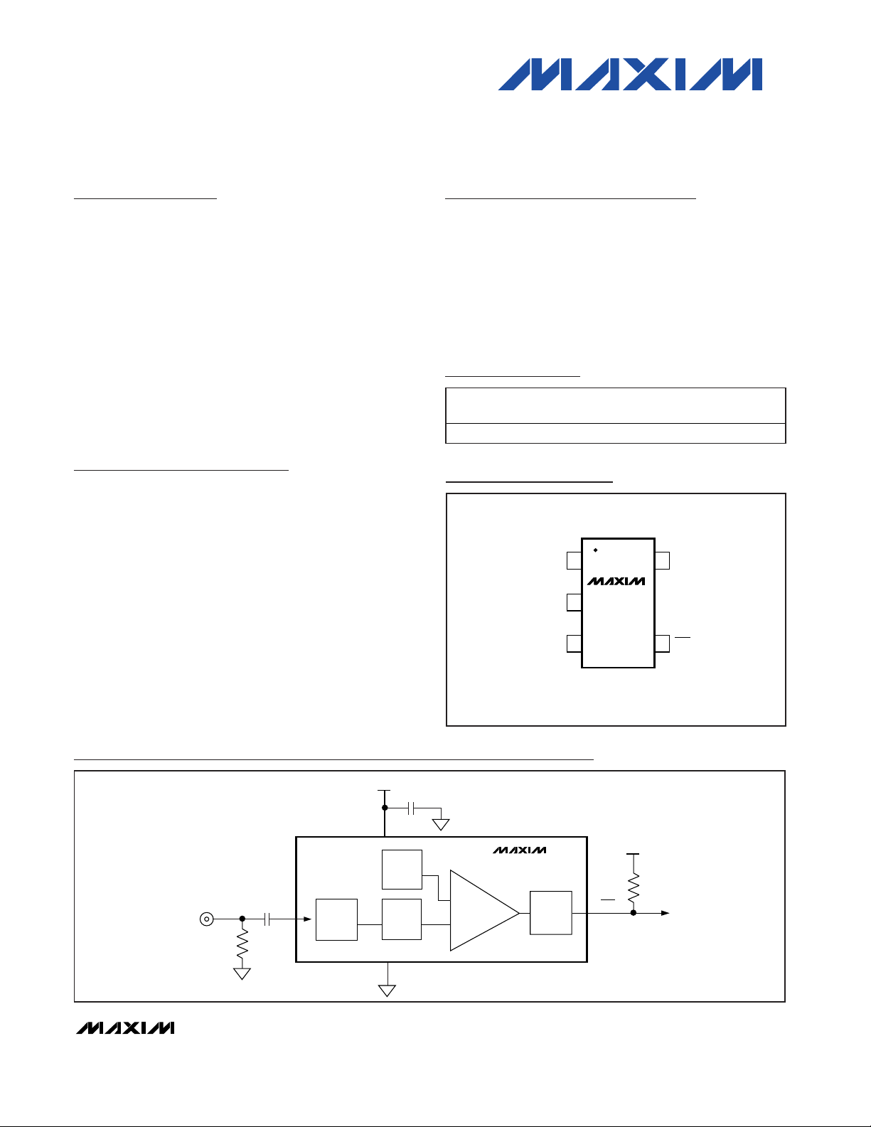
Pin Configuration
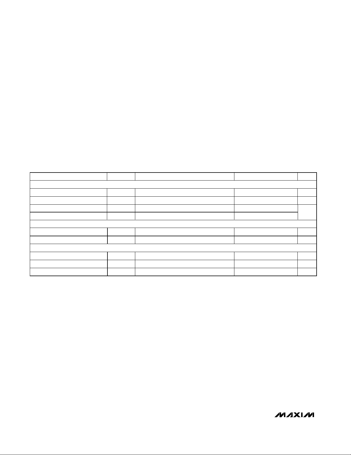
CLAMP
LPF
SYNC
DETECTOR
GND
LOS
75Ω
+5V
0.1µF
V
CC
SYNC
SLICE
LEVEL
LOS
FILTER
V
CC
0.1µF
1kΩ
1
5
3
4
SYNC
C
IN
IN
RO
MAX7461
Functional Diagram
PACKAGE
-40°C to +85°C
TOP VIEW
15V
GND
IN
MAX7461
2
CC
34
SOT23-5
LOSGND
MAX7461
Loss-of-Sync Alarm
2 _______________________________________________________________________________________
ABSOLUTE MAXIMUM RATINGS
Stresses beyond those listed under “Absolute Maximum Ratings” may cause permanent damage to the device. These are stress ratings only, and functional
operation of the device at these or any other conditions beyond those indicated in the operational sections of the specifications is not implied. Exposure to
absolute maximum rating conditions for extended periods may affect device reliability.
VCCto GND..............................................................-0.3V to +6V
LOS to GND..............................................................-0.3V to +6V
IN to GND.................-0.3V to the lower of +6V and (V
CC
+ 0.3V)
Continuous Power Dissipation (T
A
= +70°C)
5-Pin SOT23-5 (derate 7.1mW/°C above +70°C) ......571.0mW
Maximum Current Into Any Pin .........................................±50mA
Operating Temperature Range
MAX7461EUK ...................................................-40°C to +85°C
Storage Temperature Range .............................-65°C to +150°C
Lead Temperature (soldering, 10s) .................................+300°C
Junction Temperature......................................................+150°C
ELECTRICAL CHARACTERISTICS
(VCC= +4.5V to +5.5V, GND = 0, CIN= 0.1µF, RO = 500Ω, TA = -40°C to +85°C, unless otherwise noted. Typical values are at TA=
+25°C.)
PARAMETER
SYMBOL
CONDITIONS
MIN
TYP
MAX
UNITS
AC CHARACTERISTICS
Minimum Input Sync Height
AC-coupled (Note 1) 105 130
mV
P-P
Maximum Input Voltage
AC-coupled 2.4
V
P-P
LOS Release Time t
RT
(Note 2) 1.7 2.2 2.7
LOS Detect Time t
DT
(Note 3) 1.9 3.4 4.9
ms
DIGITAL CHARACTERISTICS
Output Low Voltage V
OL
I
SINK
= 10mA 0.4 V
Logic High Leakage Current I
OLEAK
1µA
POWER REQUIREMENTS
Supply Voltage V
CC
4.5 5.0 5.5 V
Supply Current I
CC
1.7 2.2 mA
Power-Supply Noise Immunity V
PSNI
0 to 5MHz sinusoid on VCC (Note 4) 200
mV
P-P
Note 1: Minimum input sync height is the voltage above which LOS is guaranteed to be in high-impedance mode after the maximum
LOS time-constant time.
Note 2: LOS release time is the time that the video input must be continuously present before LOS goes high (inactive state).
Note 3: The LOS detect time is the time that the video input must be continuously absent before LOS goes low (active state).
Note 4: The MAX7461 LOS output is accurate with a power-supply noise level below V
PSNI
.
V
IN-MIN
V
IN-MAX
MAX7461
Loss-of-Sync Alarm
_______________________________________________________________________________________ 3
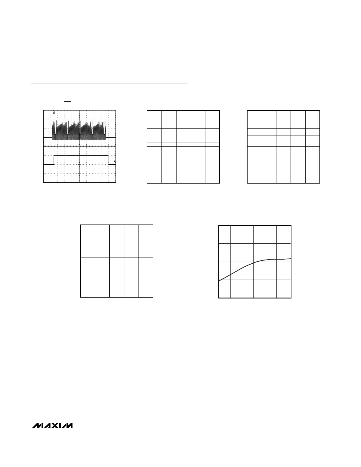
IN
500mV/div
t = 10ms/div
CVSB LOS ALERT TRANSIENT
MAX7461 toc01
LOS
5V/div
3.0
2.5
2.0
1.5
1.0
4.5 4.94.7 5.1 5.3 5.5
LOS DETECT TIME
vs. SUPPLY VOLTAGE
MAX7461 toc02
SUPPLY VOLTAGE (V)
TIME (ms)
4.0
3.5
3.0
2.5
2.0
4.5 4.94.7 5.1 5.3 5.5
LOS RELEASE TIME
vs. SUPPLY VOLTAGE
MAX7461 toc03
SUPPLY VOLTAGE (V)
TIME (ms)
0.20
0.15
0.10
0.05
0
4.5 4.94.7 5.1 5.3 5.5
SYNC HEIGHT LOS ALERT THRESHOLD
vs. SUPPLY VOLTAGE
MAX7461 toc04
SUPPLY VOLTAGE (V)
SYNC HEIGHT (V)
1.6
1.8
1.7
1.9
2.0
-40 0-20 20 40 60 80
SUPPLY CURRENT
vs. TEMPERATURE (CVBS INPUT)
MAX7461 toc05
TEMPERATURE (°C)
I
CC
(mA)
Typical Operating Characteristics
(VCC= 5V, GND = 0, CIN= 0.1µF, RO = 10kΩ, TA= +25°C, unless otherwise noted.)

MAX7461
Detailed Description
The MAX7461 single-channel LOS alarm is ideal for any
video system needing to verify the presence of a video
source. The device accepts an AC-coupled CVBS, Y,
or any video signal with sync, and pulls LOS low when
no composite sync signal is detected for more than the
LOS detect time (3.4ms, typ) at the input (IN).
Clamp
The MAX7461 features an input clamp that corrects any
DC shift, on a line-by-line basis. The external AC-coupling capacitor provides DC isolation for the input.
Lowpass Filter
The MAX7461 integrates a lowpass filter for enhanced
sync detection. The lowpass filter prevents false sync
detection by reducing color burst, chroma, and noise.
Sync Detector/LOS Filter
The sync detector looks for sync pulses greater than
the minimum sync voltage (0.13V
P-P
). If the detector
does not detect any sync pulses for 3.4ms (typ), the
LOS filter pulls LOS low. After detecting sync for at
least 2.2ms (typ), the LOS filter returns LOS to a highimpedance state. LOS is an open-drain output.
Connect a 1kΩ pullup resistor between LOS and VCC.
Power-On Reset (POR)
At power-up, LOS is pulled low and the MAX7461
checks for 2.2ms (typ) of valid sync pulses before
releasing LOS. LOS remains high impedance while a
valid sync signal is detected at the input.
Applications Information
Input Considerations
Use 0.1µF ceramic capacitors to AC-couple the input.
The input cannot be DC-coupled. The input capacitor
stores a DC level so that the video signal is clamped to
an appropriate DC voltage for proper sync detection.
Power-Supply Bypassing
Careful PC board layout is important for optimal system
performance. Do not use wire-wrapped boards or
breadboards. When possible, use a multilayer board
with a dedicated low-inductance ground plane and
supply plane. Connect all GND inputs to a single
ground plane and VCCto a single-supply plane.
Bypass VCCto GND with a 0.1µF capacitor.
Wired-OR Application
The LOS open-drain output allows the MAX7461 to be
used in wired-OR applications as shown in the automotive RSE typical application diagram of Figure 1.
Chip Information
PROCESS: BiCMOS
Loss-of-Sync Alarm
4 _______________________________________________________________________________________
Pin Description
PIN NAME FUNCTION
1IN
Video Input. Accepts CVBS, luma (Y), or any video input with sync. AC-couple IN with a series 0.1µF
capacitor.
2, 3 GND Ground
4 LOS
Loss-Of-Sync Output (Open Drain). LOS is in high impedance when sync pulses are detected, and is
pulled low when no horizontal sync signal is detected for more than the LOS detect time. LOS returns
high when sync pulses are detected for more than the LOS release time. Connect a 1kΩ pullup resistor
from LOS to V
CC
.
5VCCPower-Supply Input. Bypass to GND with a 0.1µF capacitor.

MAX7461
Loss-of-Sync Alarm
_______________________________________________________________________________________ 5
MONITOR 1
µC
SWITCH
MATRIX
AND
PROCESSING
MONITOR N
75Ω
CAMERA
RGB VIDEO SOURCE
TV
TUNER
75Ω
75Ω
1kΩ
0.1µF
0.1µF
0.1µF
V
CC
MAX7461
MAX7461
MAX7461
Figure 1. Automotive RSE System

MAX7461
Loss-of-Sync Alarm
6 _______________________________________________________________________________________
MONITOR 1
µC
SWITCH
MATRIX
AND
PROCESSING
MONITOR N
75Ω
75Ω
1kΩ
1kΩ
1kΩ
75Ω
0.1µF
0.1µF
0.1µF
CAM 1
N
1
V
CC
V
CC
V
CC
CAM 2
CAM N
MAX7461
MAX7461
MAX7461
Figure 2. Video Security System

MAX7461
Loss-of-Sync Alarm
Boblet
Maxim cannot assume responsibility for use of any circuitry other than circuitry entirely embodied in a Maxim product. No circuit patent licenses are
implied. Maxim reserves the right to change the circuitry and specifications without notice at any time.
Maxim Integrated Products, 120 San Gabriel Drive, Sunnyvale, CA 94086 408-737-7600 ______________________7
© 2006 Maxim Integrated Products Printed USA is a registered trademark of Maxim Integrated Products, Inc.
Package Information
(The package drawing(s) in this data sheet may not reflect the most current specifications. For the latest package outline information,
go to www.maxim-ic.com/packages
.)
SOT-23 5L .EPS
E
1
1
21-0057
PACKAGE OUTLINE, SOT-23, 5L
 Loading...